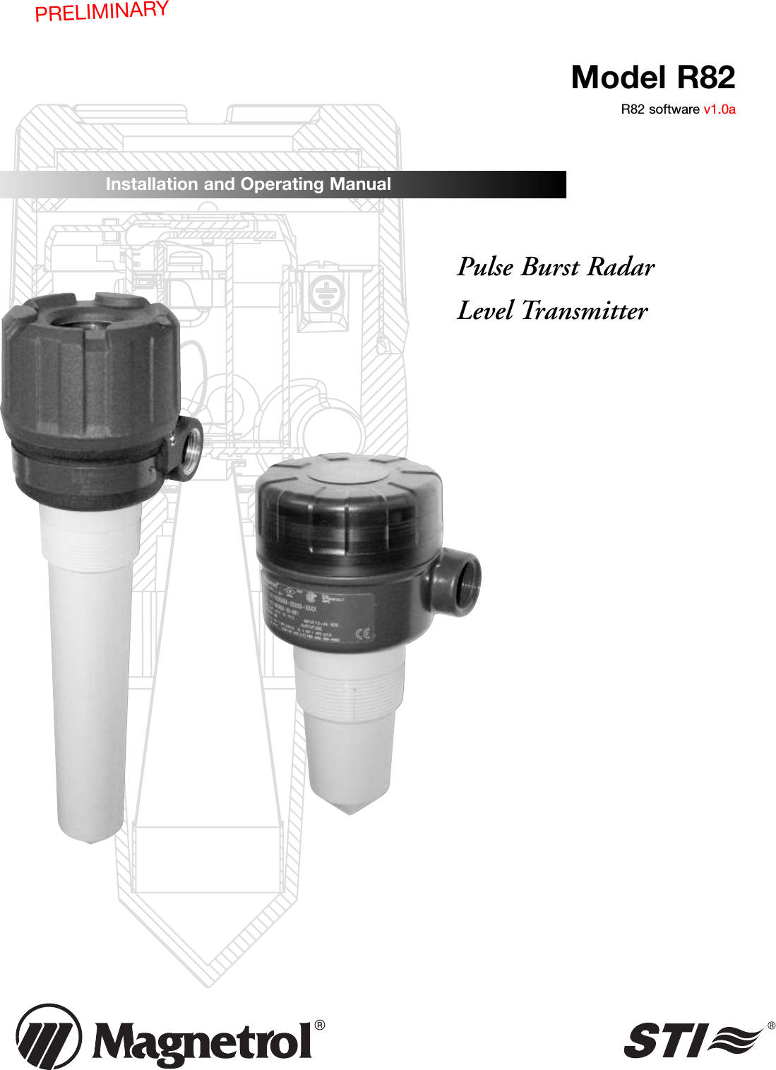
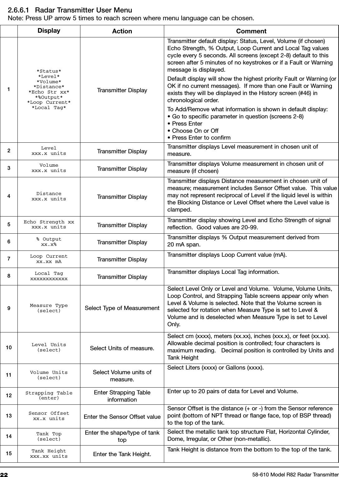
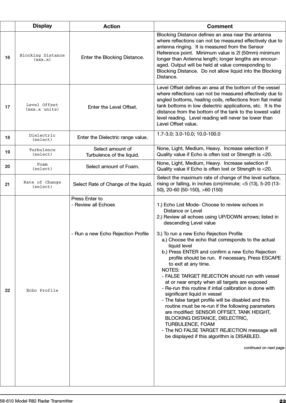
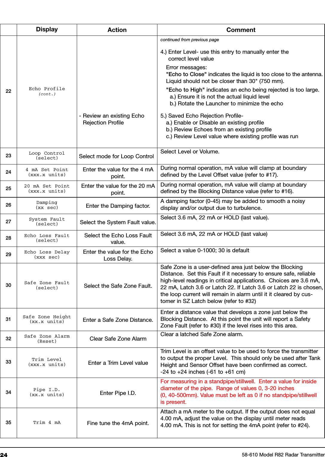
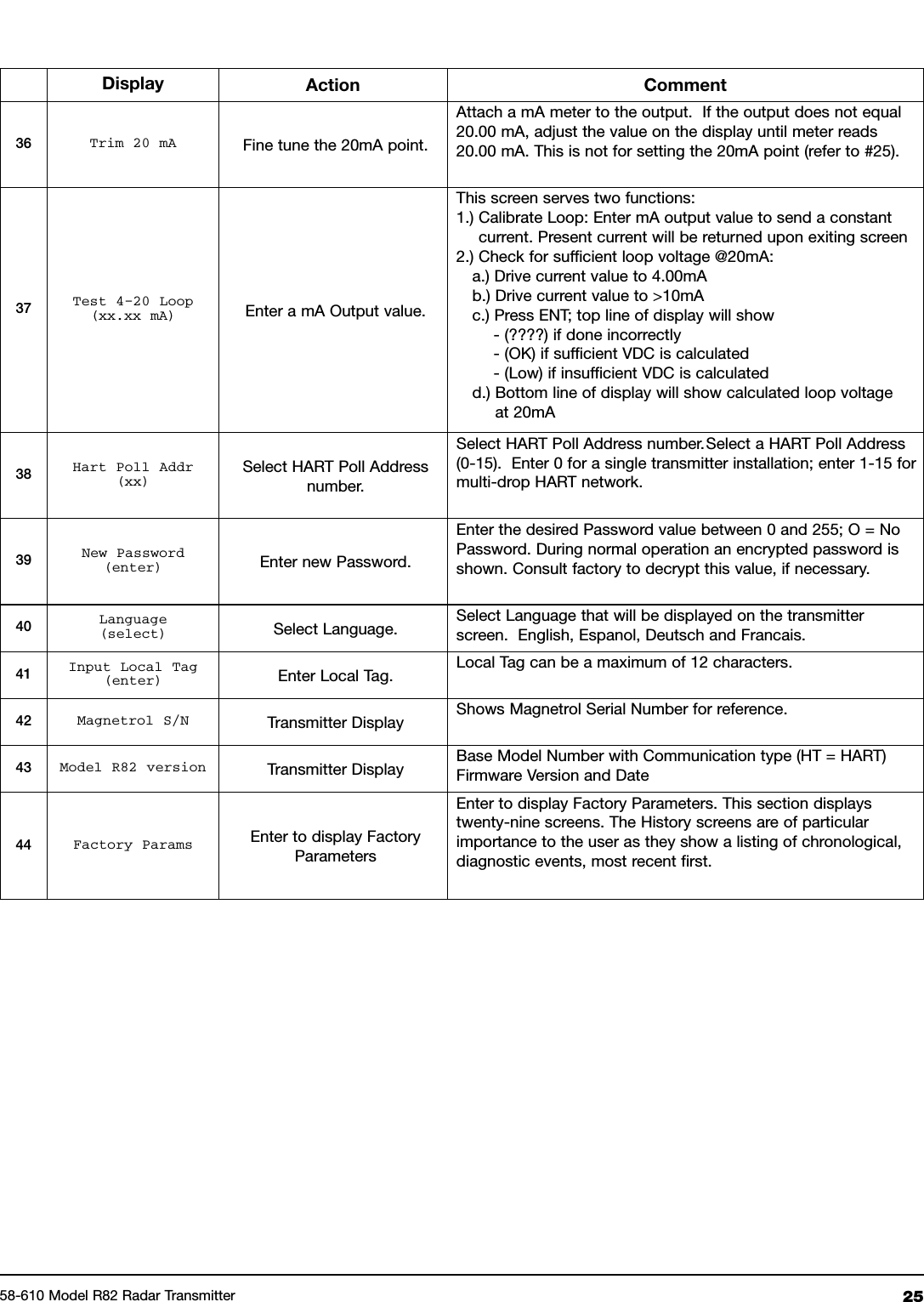
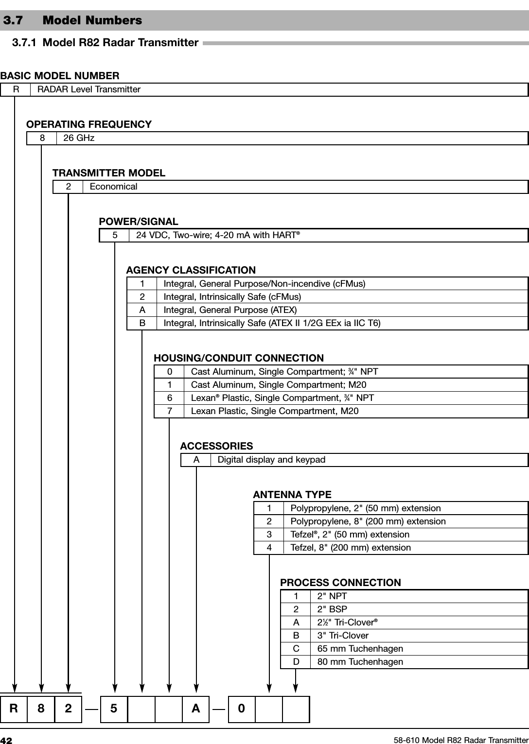
AMETEK Magnetrol USA
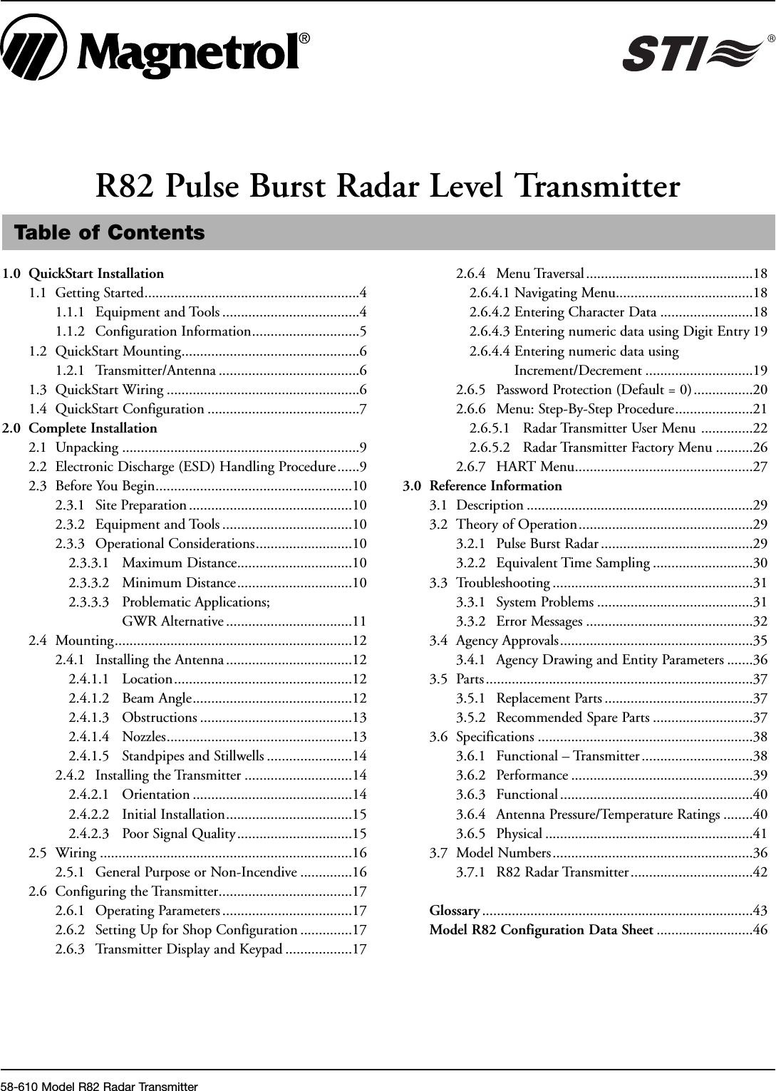
 R82 Pulse Burst Radar Level Transmitter User Manual 58 610 R82 IO

Magnetrol Pulse Burst Radar Level Transmitter 58 610 R82 IO

User Manual

Pulse Burst RadarLevel TransmitterInstallation and Operating ManualModel R82R82 software v1.0aPRELIMINARY
Read this Manual Before InstallingThis manual provides information on the R82 Radar transmitter. It isimportant that all instructions are read carefully and followed insequence. The QuickStart Installation instructions are a brief guide tothe sequence of steps for experienced technicians to follow wheninstalling the equipment. Detailed instructions are included in theComplete Installation section of this manual.Conventions Used in this ManualCertain conventions are used in this manual to convey specific types ofinformation. General technical material, support data, and safetyinformation are presented in narrative form. The following styles areused for notes, cautions, and warnings.NOTESNotes contain information that augments or clarifies an operatingstep. Notes do not normally contain actions. They follow the pro-cedural steps to which they refer.CautionsCautions alert the technician to special conditions that could injurepersonnel, damage equipment, or reduce a component’s mechani-cal integrity. Cautions are also used to alert the technician to unsafepractices or the need for special protective equipment or specificmaterials. In this manual, a caution box indicates a potentially haz-ardous situation which, if not avoided, may result in minor ormoderate injury.WARNINGSWarnings identify potentially dangerous situations or serious haz-ards. In this manual, a warning indicates an imminently hazardoussituation which, if not avoided, could result in serious injury ordeath.Safety MessagesThe Through-Air Radar system is designed for use in Category II,Pollution Degree 2 installations. Follow all standard industry proce-dures for servicing electrical and computer equipment when workingwith or around high voltage. Always shut off the power supply beforetouching any components. Although high voltage is not present in thissystem, it may be present in other systems.Electrical components are sensitive to electrostatic discharge. To pre-vent equipment damage, observe safety procedures when working withelectrostatic sensitive components.Low Voltage DirectiveFor use in Installations Category II, Pollution Degree 2. If equipmentis used in a manner not specified by the manufacturer, protection pro-vided by equipment may be impaired.NOTE: This equipment has been tested and found to comply withthe limits for a Class B digital device, pursuant to Part 15 of theFCC Rules. These limits are designed to provide reasonable protec-tion against harmful interference in a residential installation. Thisequipment generates, uses and can radiate radio frequency energyand, if not installed and used in accordance with the instructions,may cause harmful interference to radio communications. However,there is no guarantee that interference will not occur in a particularinstallation. If this equipment does cause harmful interference to theradio or television reception, which can be determined by turningthe equipment off and on, the use is encouraged to try to correct theinterference by one or more of the following measures:•Reorient or relocate the receiving antenna.• Increase the separation between the equipment and receiver.• Connect the equipment into an outlet on a circuit different fromthat to which the receiver is connected.• Consult the dealer or an experienced radio/TV technician forhelp.Any unauthorized changes or modifications not expressly approved byMagnetrol International, Incorporated could void user’s authority tooperate this equipment.WARNING! Explosion hazard. Do not connect or disconnect designsrated Explosion-proof or Non-incendive unless power has beenswitched off and/or the area is known to be non-hazardousNotice of Copyright and LimitationsMagnetrol & Magnetrol logotype are registered trademarks ofMagnetrol International.Copyright © 2009 Magnetrol International, IncorporatedAll rights reserved.Performance specifications are effective with date of issue and are sub-ject to change without notice. Magnetrol reserves the right to makechanges to the product described in this manual at any time withoutnotice. Magnetrol makes no warranty with respect to the accuracy of theinformation in this manual.WarrantyAll Magnetrol electronic level and flow controls are warranted free ofdefects in materials or workmanship for one full year from the date oforiginal factory shipment.If returned within the warranty period; and, upon factory inspection ofthe control, the cause of the claim is determined to be covered underthe warranty; then, Magnetrol will repair or replace the control at nocost to the purchaser (or owner) other than transportation.Magnetrol shall not be liable for misapplication, labor claims, direct orconsequential damage or expense arising from the installation or use ofequipment. There are no other warranties expressed or implied, exceptspecial written warranties covering some Magnetrol products.Quality AssuranceThe quality assurance system in place at Magnetrol guarantees thehighest level of quality throughout the company. Magnetrol iscommitted to providing full customer satisfaction both in qualityproducts and quality service.Magnetrol’s quality assurance system is registeredto ISO 9001 affirming its commitment to knowninternational quality standards providing thestrongest assurance of product/service qualityavailable.58-610 Model R82 Radar Transmitter
Table of Contents1.0 QuickStart Installation1.1 Getting Started..........................................................41.1.1 Equipment and Tools .....................................41.1.2 Configuration Information.............................51.2 QuickStart Mounting................................................61.2.1 Transmitter/Antenna ......................................61.3 QuickStart Wiring ....................................................61.4 QuickStart Configuration .........................................72.0 Complete Installation2.1 Unpacking ................................................................92.2 Electronic Discharge (ESD) Handling Procedure......92.3 Before You Begin.....................................................102.3.1 Site Preparation ............................................102.3.2 Equipment and Tools ...................................102.3.3 Operational Considerations..........................102.3.3.1 Maximum Distance...............................102.3.3.2 Minimum Distance...............................102.3.3.3 Problematic Applications;GWR Alternative ..................................112.4 Mounting................................................................122.4.1 Installing the Antenna..................................122.4.1.1 Location................................................122.4.1.2 Beam Angle...........................................122.4.1.3 Obstructions .........................................132.4.1.4 Nozzles..................................................132.4.1.5 Standpipes and Stillwells .......................142.4.2 Installing the Transmitter .............................142.4.2.1 Orientation ...........................................142.4.2.2 Initial Installation..................................152.4.2.3 Poor Signal Quality...............................152.5 Wiring ....................................................................162.5.1 General Purpose or Non-Incendive ..............162.6 Configuring the Transmitter....................................172.6.1 Operating Parameters ...................................172.6.2 Setting Up for Shop Configuration ..............172.6.3 Transmitter Display and Keypad ..................172.6.4 Menu Traversal.............................................182.6.4.1 Navigating Menu.....................................182.6.4.2 Entering Character Data .........................182.6.4.3 Entering numeric data using Digit Entry 192.6.4.4 Entering numeric data usingIncrement/Decrement .............................192.6.5 Password Protection (Default = 0)................202.6.6 Menu: Step-By-Step Procedure.....................212.6.5.1 Radar Transmitter User Menu ..............222.6.5.2 Radar Transmitter Factory Menu ..........262.6.7 HART Menu................................................273.0 Reference Information3.1 Description .............................................................293.2 Theory of Operation...............................................293.2.1 Pulse Burst Radar .........................................293.2.2 Equivalent Time Sampling ...........................303.3 Troubleshooting ......................................................313.3.1 System Problems ..........................................313.3.2 Error Messages .............................................323.4 Agency Approvals....................................................353.4.1 Agency Drawing and Entity Parameters .......363.5 Parts ........................................................................373.5.1 Replacement Parts ........................................373.5.2 Recommended Spare Parts ...........................373.6 Specifications ..........................................................383.6.1 Functional – Transmitter ..............................383.6.2 Performance .................................................393.6.3 Functional ....................................................403.6.4 Antenna Pressure/Temperature Ratings ........403.6.5 Physical ........................................................413.7 Model Numbers......................................................363.7.1 R82 Radar Transmitter.................................42Glossary .........................................................................43Model R82 Configuration Data Sheet ..........................46R82 Pulse Burst Radar Level Transmitter58-610 Model R82 Radar Transmitter
41.0 QuickStart InstallationThe QuickStart Installation procedures provide the keysteps for mounting, wiring, and configuring the R82 radarlevel transmitter. These procedures are intended for experi-enced installers of electronic level measurement instruments.See Complete Installation, Section 2.0, for detailed installa-tion instructions.1.1 Getting StartedBefore beginning the QuickStart Installation procedures,have the right equipment, tools, and information available.1.1.1 Equipment and ToolsNo special tools are needed. The following items arerecommended:• Threaded antenna and transmitter . . . . . . 2" (50 mm)• Flat-blade screwdriver• Digital multimeter or volt/ammeter . . . . . Optional• 24 VDC (23 mA) power supply. . . . . . . . Optional58-610 Model R82 Radar Transmitter
51.1.2 Configuration InformationSome key information is needed to configure the R82 radartransmitter. Complete the following operating parameterstable before beginning configuration.NOTE: The transmitter will already be configured if this information wasprovided with the order.Display Question AnswerUnits What units of measurement will beused? _____________Will the unit measure in Level orVolume? _____________What are the Volume units? _____________What is the relationship between Leveland Volume? (Enter up to 20 points) _____________Sensor What is the distance from the top (100%)Offset of the tank and the Sensor Referencepoint (bottom of NPT thread, top of BSPthread, or face of flange?) _____________Tank Top Is the Tank Top Flat, Horizontal Cylinder,Dome, Irregular or other (non-metallic)? _____________Tank What is the tank height? _____________Height NOTE: Sensor Offset + Tank Height =Distance from processconnection to tank bottomBlocking What is the distance from SensorDistance Reference point to Maximum Level?Maximum level should never be lessthan 15" (375 mm) from the bottom of theprocess connection (threaded or flanged). _____________Level Is there a region at the very bottom of theOffset vessel that cannot be measured due toheating coils, angle tank bottom, etc.? _____________Dielectric What is the dielectric of the processmedium? _____________Turbulence Is turbulence a consideration? _____________Foam Will there be foam on the surface? _____________Rate of What is the maximum rate the levelChange will rise or fall? _____________4.0 mA What is the 0% reference point for theSetpoint 4.0 mA value? _____________20.0 mA What is the 100% reference point forSetpoint the 20.0 mA value? _____________58-610 Model R82 Radar Transmitter
61.2 QuickStart Mounting1.2.1 Transmitter/Antenna1. The device is manufactured as one unit that includes thetransmitter and antenna.2. Remove any protective material from the antenna beforeinstalling.3. Install the transmitter/antenna into the process connection.If threaded, tighten securely by hand using the housing forgrip. Ensure there is no cross-threading and do not overtighten as this may cause damage to the plastic threads.4. Adjust the beam position by turning the internal launcheradjustment (Fig ??). The internal launcher adjustment isnumbered 1-18 that equates to 10-180 degrees of adjust-ment; 9 is the midpoint where long axis of the beam is at45 degrees to the Display (Fig ??). After positioning thetransmitter display, rotate the launcher adjustment so thebeam is at an angle of 45° to a line from the radar unit tothe nearest tank wall (Fig ??). Do not optimize the Quality(signal strength) at one level in the vessel.• Do not place insulating material around any part of theRadar transmitter including the antenna process connection.1.3 QuickStart WiringNOTE: Make sure the electrical wiring to the R82 radar transmitter iscomplete and in compliance with all regulations and codes.1. Remove the cover of the wiring compartment.2. Attach a conduit fitting and mount the conduit plug in thespare opening. Pull the power supply wire through the con-duit fitting.3. Connect shield to an earth ground at power supply andleave floating at the transmitter.4. Connect the positive supply wire to the (+) terminal and thenegative supply wire to the (-) terminal. For ExplosionProof Installations, see Wiring, Section 2.5.3.5. Replace the cover and tighten.58-610 Model R82 Radar TransmitterFigure XBeam Orientation with #9Launcher PositionGroundLauncher Adjustment(with #9 Position Selected)45°(+)(-)
758-610 Model R82 Radar TransmitterGroundLauncherAdjustment(+)(-)1.4 QuickStart ConfigurationThe Radar transmitter comes factory-calibrated and can beconfigured in minutes for specific applications. Bench con-figuration provides a convenient and efficient way to set upthe transmitter before going to the tank site to complete theinstallation. The minimum configuration instructions fol-low. Use the information from the operating parameterstable before beginning configuration. See ConfigurationInformation, Section 1.1.2.1. Power-up the transmitter.During normal operation the display changes every 3 sec-onds to show one of the various measured values that can bechosen for display: Level, Volume, Distance, Echo Strength,%Output, Loop Current and Local Tag.2. Remove the cover of the electronic compartment.3. The Pushbuttons offer multiple forms of functionality formenu navigation and data entry. (See Section 2.6.3???? forcomplete explanation)UP arrow moves up through menu or increases dis-played valueDOWN arrow moves down through menu or decreasesdisplayed valueBACK arrow exits a branch of the menu or exits with-out accepting entered valueENTER arrow enters a branch of the menu or acceptsentered valueIf a PASSWORD is requested, enter it now. The Default=0(no password necessary). The last character in the firstline of the display changes to an exclamation point (!).
858-610 Model R82 Radar TransmitterSelect if Level or Level & VolumeSelect the Units of measure for thedisplay (cm, inches, meters, feet).Enter the Sensor Offset value; thedistance from the top (100%) point ofthe vessel to the Sensor Referencepoint (bottom of an NPT thread, topof a BSP thread, face of a flange).Select the type of Tank Top; choicesare Flat, Horizontal cylinder, Dome,Irregular, or Other (nonmetallic).Enter the exact Tank Height; inaccu-rate values will create inaccurate levelreadings.Enter the Blocking Distance; thedistance close to the antenna wheremeasurement is unreliable. Minimumvalue = 15" (375 mm)???? as meas-ured from the process connection.Enter the Level Offset; the distanceat the bottom of the vessel wheremeasurement may be unreliable dueto heating coils, irregular bottom, etc.Select the proper Dielectric range forthe process medium.Select the value of Turbulence thatcorresponds to the application.Select the Foam value that corre-sponds to the application.Select the Rate of Change value thatcorresponds to the maximum rate thelevel will rise or fall.Examine the list of reflections detect-ed by the transmitter to ensure theactual level reflection is present. Itmay be necessary to rotate thelauncher for optimal performance.Run the Echo Rejection routine bychoosing the correct LEVEL therebycancelling all false reflections in thevessel; ideally with tank empty.Enter the minimum level value (0%)for the 4 mA point.Enter the maximum level (100%) forthe 20 mA point.MeasureTypeLevel Units(select)Sensor OffsetxxxxTank Top(select)Tank HeightxxxxBlocking DistxxxxLevel Offsetxxx.xDielectric(select)Turbulence(select)Foam(select)Rate of Change(select)Set 4mAxx.xEcho ProfileSet 20mAxx.xSensor OffsetTank HeightBlockingDistanceLevelOffset2178911101213145364The following configuration entries are the minimumrequired for configuration. The default password is 0.1234568910111213147
958-610 Model R82 Radar Transmitter2.0 Complete InstallationThis section provides detailed procedures for properlyinstalling, configuring, and, as needed, troubleshooting theR82 Radar Level Transmitter.2.1 UnpackingUnpack the instrument carefully. Make sure all componentshave been removed from the packing material. Check all thecontents against the packing slip and report any discrepanciesto the factory.Before proceeding with the installation, do the following:• Inspect all components for damage. Report any damage tothe carrier within 24 hours.• Make sure the nameplate model number on the transmitteragree with the packing slip and purchase order.• Record the model and serial numbers for future referencewhen ordering parts.2.2 Electrostatic Discharge (ESD)Handling ProcedureMagnetrol’s electronic instruments are manufactured to thehighest quality standards. These instruments use electroniccomponents that may be damaged by static electricity pres-ent in most work environments.The following steps are recommended to reduce the risk ofcomponent failure due to electrostatic discharge.• Ship and store circuit boards in anti-static bags. If an anti-static bag is not available, wrap the board in aluminum foil.Do not place boards on foam packing materials.• Use a grounding wrist strap when installing and removingcircuit boards. A grounded workstation is recommended.• Handle circuit boards only by the edges. Do not touchcomponents or connector pins.• Make sure that all electrical connections are completelymade and none are partial or floating. Ground all equip-ment to a good, earth ground.
102.3 Before You Begin2.3.1 Site PreparationEach R82 Radar transmitter is built to match the specificphysical specifications of the required installation. Makesure the antenna connection is correct for the threaded orflanged mounting on the vessel or tank where the transmit-ter will be placed. See Mounting, Section 2.4.Make sure that the wiring between the power supply andRadar transmitter are complete and correct for the type ofinstallation.When installing the Radar transmitter in a general purposeor hazardous area, all local, state, and federal regulations andguidelines must be observed. See Wiring, Section 2.5.2.3.2 Equipment and ToolsNo special tools are needed. The following items arerecommended:• Threaded antenna and transmitter . . . . . . 2" (50 mm)• Torque wrench . . . . . . . . . . . . . . . . . . . . . highly desirable• Flat-blade screwdriver• Digital multimeter or volt/ammeter . . . . . Optional• 24 VDC (23 mA) power supply. . . . . . . . Optional2.3.3 Operational ConsiderationsRadar applications are characterized by three basic conditions;Dielectric, Distance (measuring range) and Disturbances(turbulence, foam, false targets, multiple reflections and rateof change).2.3.3.1 Maximum DistanceThe chart below shows the maximum measuring range(Distance) of each antenna based on fundamental condi-tions of Dielectric, Distance and Turbulence. Maximum dis-tance is calculated as Tank Height + Sensor Offset(see page 17). It is measured from the Sensor ReferencePoint (bottom of NPT thread, top of BSP thread or face ofa flange).2.3.3.2 Minimum DistanceIf the liquid level is allowed onto the antenna, noise andmedia build-up drastically decrease reliable measurement.Liquid should not be allowed closer than 15 inches(380 mm) from the bottom of the antenna mountingthreads (or face of sanitary flange).58-610 Model R82 Radar TransmitterDielectric Turbulence R821.7-3.0None 26 (8.0)Light, < 0.5" 21 (6.4)Moderate, < 1.0" 14 (4.3)Heavy, > 1.0" 7 (2.1)3.0-10.0None 33 (10.1)Light, < 0.5" 26 (7.9)Moderate, < 1.0" 19 (5.8)Heavy, > 1.0" 12 (3.7)10.0-100None 40 (12)Light, < 0.5" 32 (9.8)Moderate, < 1.0" 24 (7.3)Heavy, > 1.0" 17 (5.2)MAXIMUM DISTANCE feet (meters)
1158-610 Model R82 Radar Transmitter2.3.3.3 Problematic Applications; GWR AlternativeSome application concerns can be problematic for Radar.For these, Guided Wave Radar is recommended:• Extremely low dielectric media (εr<2.0)• Very weak reflections from the liquid surface, particularlyduring turbulence, can cause poor performance.• Tanks heavily cluttered with false targets (mixers, pumps,ladders, pipes, etc.)• During times of very low liquid levels of low dielectric media,the metal tank bottom may be detected deteriorating per-formance.2-inch (50 mm) Antenna 8-inch (200 mm) Antenna13"(330 mm)7"(178 mm)15" (380 mm) Minimum(measured frombottom of threads orflange face)2-inch (50 mm)AntennaMaximum Recess (m) is 2 ×Nozzle Diameter (d)(example: 2" diameter nozzle)8-inch (200 mm)AntennaMaximumLiquid LevelMaximumLiquid Levelmd15"(380 mm)2" (50 mm)4" (100 mm)15"(380 mm)8" (200 mm)9" (225 mm)3" (75 mm)4" (100 mm)dFigure X<Caption>Figure X<Caption>
12 58-610 Model R82 Radar Transmitter• Foam can either absorb or reflect the microwave energydepending upon the depth, dielectric, density and wallthickness of the bubbles. Due to typical variations in theamount (depth) of foam, it is impossible to quantify per-formance. It may be possible to receive most, some or noneof the transmitted energy.• Extremely high liquid levels (Overflow) conditions whenliquid very near the antenna can cause erroneous readingsand measurement failure.2.4 MountingThe R82 Radar transmitter can be mounted to a vesselusing a variety of process connections. Generally, either athreaded or flanged connection is used.2.4.1 Installing the AntennaBefore installing, make sure:• Process temperature, pressure, dielectric, turbulence anddistance are within the antenna specifications for theinstallation.• End of antenna is protected from bending or breaking.• Insulating material is not placed around any part of theRadar transmitter including the antenna flange.• Antenna is being mounted in the optimal location. See fol-lowing sections: Location, Beam Angle, Obstructions andNozzles for specific information.2.4.1.1 LocationIdeally, the Radar transmitter should be mounted providingan unobstructed signal path to the liquid surface where itshould illuminate (with microwave energy) the largest,possible surface area. See Section 2.4.1.2, Beam Angle.Unavoidable obstacles will produce reflections that must beminimized during field configuration. See Section 2.6.5.1,Target Rejection. Mount in a location equal to 1⁄2the radiusof tank top. Do not mount in center of vessel nor closerthan 10" (25 cm) of tank wall.2.4.1.2 Beam AngleThe various antenna designs exhibit different beam patterns.Ideally, the beam pattern should illuminate the maximumliquid surface with a minimum striking other objects in thevessel including the tank wall. Use these drawings to deter-mine the optimum installation location.1/2Radius> 10"(25 cm)WDistance Beam SpreadFeet Meters Feet Meters10 3 1.7 0.5220 6 3.5 1.0530 9 5.2 1.5740 12 7.0 2.10
1358-610 Model R82 Radar Transmitter2.4.1.3 ObstructionsAlmost any object that falls within the beam pattern willcause reflections that may be misinterpreted as a false liquidlevel. Although Model R82 has a powerful False TargetRejection routine, all possible precautions should be takento minimize false target reflections with proper installationand orientation.2.4.1.4 NozzlesImproper installation in a nozzle creates “ringing” whichwill adversely affect measurement. Refer to Figure 9???. TwoAntenna extension lengths are offered to allow the R82transmitter to work reliably in a variety of nozzles.The Minimum Blocking Distance of 15" (380 mm) isalways measured from the bottom of the threads or face ofa flange. The related distance as measured from the end ofthe antenna varies depending on the antenna extensionchosen. See Figure ??.The narrow beam width of the 26 GHz, R82 does allowmounting so that the antenna can be recessed inside thenozzle. Optimally, the recessed dimension should neverexceed 2×the nozzle diameter. See Figure??????NOTE: If the antenna is recessed in a nozzle it is mandatory that EchoRejection is run to eliminate any possibility of false reflections.2-inch (50 mm)AntennaMaximum Recess (m) is 2 ×Nozzle Diameter (d)(example: 2" diameter nozzle)8-inch (200 mm)AntennaMaximumLiquid LevelMaximumLiquid Levelmd15"(380 mm)2" (50 mm)4" (100 mm)15"(380 mm)8" (200 mm)9" (225 mm)3" (75 mm)4" (100 mm)d
14 58-610 Model R82 Radar Transmitter2.4.1.5 Standpipes and StillwellsThe R82 can be mounted in a standpipe or stillwell butcertain considerations should be given:• Metal stillwells only: 2" (Sched 40 max.) to 4" (50–100 mm).• Diameter must be consistent throughout length; no reducers.• Stillwell length must cover complete range of measurement(i.e., liquid must be in stillwell).• Welds should be smooth.• Vents: holes <0.125" diameter, slots <0.125" width.• If an isolation valve is used, it must be a full port ball valvewith an I.D. equal to the pipe diameter.• Bridles/Bypass Installations: The launcher should be rotated90° from process connections.• Configuration must include an entry for PIPE I.D.See Section 2.6.5.1, Item 34- PIPE I.D.• There will be some increased dielectric sensitivity; systemGAIN will be reduced when PIPE ID >0.2.4.2 Installing the TransmitterInstall the Transmitter with its integral antenna by threadinginto the vessel. DO NOT OVERTIGHTHEN as this maycause damage to the plastic threads.• Do not place insulating material around any part of theradar transmitter including the antenna flange.• Installation for NEMA 6P/IP 68- the transmitter can beinstalled to allow for temporary submergence to 6 feet (1.8m):- use TFE paste to seal conduit entries and antenna processconnection- Do not overtighten housing cover; O-ring developswater-tight seal without excessive tightening2.4.2.1 OrientationThe R82 transmitter utilizes a linearly polarized, microwavebeam that can be rotated to improve its performance. Properorientation can minimize unwanted target reflections, decreasesidewall reflections (multipath) and maximize direct reflec-tions from the liquid surface.The internal launcher mechanism can be turned to optimizeperformance. The launcher has index marks numbered1–18 (representing 10–180 degrees). The Polarizationpattern is at 45 degrees to the transmitter display whenthe mechanism is at the #9 position.Figure XBeam Orientation with #9Launcher PositionFigure XR82 Mounted in Stillwell (Bridle)GroundLauncher Adjustment(with #9 Position Selected)45°(+)(-)45°Figure XPolarization Pattern
1558-610 Model R82 Radar Transmitter2.4.2.2 Initial InstallationIdeally, the transmitter should be mounted half the radiusfrom the tank wall. In a typical vertical tank, the Launchershould be adjusted so the polarization pattern is 45 degreesto the closest tank sidewall. See Figures ? & ?.For horizontal cylindrical vessels, aim beam down the longaxis of the vessel. Do not optimize the Quality (signalstrength) at one level in the vessel.A transmitter mounted within 10" (25 cm) of a tank wallmay demand orientation adjustments to limit multipathand optimize performance. See Section 2.4.2.3, Poor EchoStrength.2.4.2.3 Poor Echo StrengthPoor signal quality has many potential causes. Following aretwo initial areas for investigation.Launcher Orientation: Initial launcher orientation is always45 degrees (see Sections 2.4.1 & 2.4.2). In tall vessels andwhen antenna is mounted close to the tank wall, improve-ment in signal quality may be attained by rotating thelauncher to 90 degrees.Signal Loss: If the Level signal is lost repeatedly at a specificpoint in the vessel, it is usually a symptom that multipath(side-wall reflections) are causing cancellation by returningto the transmitter exactly 180° out of phase with the Levelsignal. Utilize the following procedure:• Go to transmitter screen #5 which shows both Level andEcho Strength.• Bring the Level up (or down) to the exact point where thesignal is repeatedly lost. Monitor the Echo Strength thispoint is being approached. The Echo Strength will degradeto a low point before it begins to increase.• At the poorest Echo Strength slowly rotate the launcher1–2 notches. Allow the unit to stabilize for approximatelyone minute. Repeat this process until the Echo Strength isoptimized.1/2 RadiusOrientationMechanismin #9position45°90°Figure XTop ViewMounted 1⁄2radiusFigure XxxxxGroundLauncherAdjustment(+)(-)
16 58-610 Model R82 Radar Transmitter2.5 WiringCaution The R82 Radar transmitter operates at voltages of 16–36VDC (GP) and 16-28.6 VDC (IS). Higher voltage will dam-age the transmitter.Wiring between the power supply and the Radar transmittershould be made using 18–22 AWG shielded twisted pairinstrument cable. Within the transmitter enclosure, con-nections are made to the terminal strip and the groundconnections. Trim excess wiring to minimize clutter, noiseissues and allow access to Launcher adjustment (seeFigure ??). The directions for wiring the Radar transmitterdepend on the application:• General Purpose or Non-incendive (Cl I, Div. 2)• Intrinsically SafeNOTE: For ATEX installation guidelines refer to bulletin BE 58-610.2.5.1 General Purpose or Non-incendive (Cl I, Div. 2)A general purpose installation does not have flammablemedia present. Areas rated non-incendive (Cl I, Div. 2) haveflammable media present only under abnormal conditions.No special electrical connections are required. If flammablemedia is contained in the vessel, the transmitter must beinstalled per Cl I, Div. 1 standards of area classification.To install General Purpose or Non-incendive wiring:1. Remove the cover to the wiring compartment of the trans-mitter. Install the conduit plug in the unused opening.2. Install a conduit fitting and pull the supply wires.3. Connect shield to an earth ground at power supply andleave floating at the transmitter.4. Connect an earth ground wire to the nearest green groundscrew per local electrical code (not shown in illustration).5. Connect the positive supply wire to the (+) terminal andthe negative supply wire to the (-) terminal.6. Replace cover to the wiring compartment of transmitter.GroundLauncherAdjustment(+)(-)Figure Xxxxx
1758-610 Model R82 Radar Transmitter2.6 Configuring the TransmitterThe Radar transmitter comes factory-calibrated and can beconfigured in minutes for specific applications.Before configuring the transmitter, collect the operatingparameters information. Then, power-up the transmitteron the bench and follow through the step-by-step proce-dures for the menu-driven transmitter display. Informationon configuring the transmitter using a HART communica-tor is given in Configuration Using HART (Section 2.7).2.6.1 Operating ParametersSome key information is needed to configure the Radartransmitter. If necessary, complete the configuration infor-mation table in Section 1.1.2.2.6.2 Setting Up for Shop ConfigurationThe Radar transmitter can be configured at a test bench byconnecting a 24 VDC power supply directly to the trans-mitter terminals. The connections are illustrated in theaccompanying diagrams. An optional digital multimeter isshown if current measurements are desired.When using a HART communicator for configuration, aminimum 250 Ωline load resistance is required. See theHART communicator manual for more information.2.6.3 Transmitter Display and KeypadThe R82 transmitter has a local user interface consisting ofa 2-line by 16-character liquid-crystal display (LCD) and4-push-button keypad. All transmitter measurement dataand configuration information is shown in the LCD.The transmitter default display is the measurement screen.It cycles every 5 seconds to display *STATUS*, *LEVEL*,*ECHO STRENGTH*, *%OUTPUT*, *LOOP CUR-RENT* and *LOCAL TAG* information. The transmit-ter defaults to this display after 5 minutes if no keystrokesare sensed. You can also access each of these screens indi-vidually. The display will not return to the default screenif left in one of these screens. For example, the device canbe left to read only LEVEL indefinitely if left in thisscreen.GroundLauncherAdjustment(+)(-)Figure Xxxxx
2.6.4 Menu TraversalThe push buttons offer multiple forms of functionality18 58-610 Model R82 Radar TransmitterPush button Keystroke ActionUp Moves to the previous item in the menu branchDown Moves to the next item in the menu branchBack Moves back one level to the previous higherbranch itemEnter Enters into the lower level branch or switches tothe entry modePush button Keystroke ActionUpMoves to the previous character (Z,Y,X,W). If helddown the characters scroll until the push buttonis released.DownMoves to the next item character (A,B,C,D). Ifheld down the characters scroll until the pushbutton is released.BackMoves the cursor back to the left. If the cursor isalready at the leftmost position, then the screenis exited without changing the original tagcharacters.EnterMoves the cursor forward to the right. If thecursor is at the rightmost position, then thenew tag is saved.2.6.4.1 Navigating Menu2.6.4.2 Entering Character Data
1958-610 Model R82 Radar TransmitterNOTES: All numeric values are left-justified, and new values areentered from left to right. A decimal point can be entered afterthe first digit is entered, such that .9 is entered as 0.9.A few configuration items can have a negative value. In thiscase, the leftmost position is reserved for the sign (either “-“for a negative value, or “+” for a positive value)Push button Keystroke ActionUpMoves up to the next highest digit (0,1,2,3,....,9).If held down the digits scroll until the push buttonis released.DownMoves down to the next lowest digit(9,8,7,6,….,0). If held down the digits scroll untilthe push button is released.BackMoves the cursor to the left and deletes a digit. Ifthe cursor is already at the leftmost position,then the screen is exited without changing thepreviously saved value.EnterMoves the cursor to the right. If the cursor islocated at a blank character position, the newvalue is saved.Push button Keystroke ActionUpIncrements the displayed value. If held down thedigits scroll until the push button is released.Depending on which screen is being revised, theincrement amount may increase by a factor of 10after the value has been incremented 10 times.DownDecrements the displayed value. If held down thedigits scroll until the push button is released.Depending on which screen is being revised, thedecrement amount may increase by a factor of 10after the value has been decremented 10 times.BackReturns to the previous menu without changingthe original value, which is immediately redis-played.Enter Accepts the displayed value and returns to theprevious menu.2.6.4.3 Entering numeric data using Digit Entry2.6.4.4 Entering numeric data using Increment/Decrement
20 58-610 Model R82 Radar Transmitter2.6.5 Password Protection (Default = 0)The Radar transmitter is password protected to restrictaccess to certain portions of the menu structure that affectthe operation of the system. When the proper password isentered, an exclamation point (!) appears as the last charac-ter of the first line of the display. The password can bechanged to any numerical value up to 255. The passwordis required whenever configuration values are changed.The default password installed in the transmitter at the fac-tory is 0 (password disabled). The last step in the configura-tion menu provides the option to enter a new password. If0 is entered as a password, the transmitter is no longer pass-word protected and any value in the menu can be altered(except diagnostic values) without entering a confirmingpassword.NOTE: If the password is not known, the menu item New Password(Section 2.6.6.1, item #39) displays an encrypted value repre-senting the present password. Call the factory with thisencrypted value to determine the actual password.
2158-610 Model R82 Radar Transmitter2.6.6 Menu: Step-By-Step ProcedureThe following table provides a complete explanation of thesoftware menus displayed by the Radar transmitter. Use thistable as a step-by-step guide to configure the transmitter.The first column presents the menus shown on the trans-mitter display. The displays are in the order they wouldappear if the arrow keys were used to scroll through themenu. The numbers are not shown on the display. Theyare provided as a reference only.The second column provides the actions to take whenconfiguring the transmitter. Additional information or anexplanation of an action is given in the third column.The following drawings are provided as reference for theconfiguration procedure.Use of the included PACTware™PC program is highlyrecommended and invaluable for troubleshooting andadvanced calibration. A HART RS232 or USB modem(purchased separately) is required. See MagnetrolPACTware™bulletin 59-101.TankHeightSensor Offset + Tank Height =Distance from processconnection to tank bottom20 mA4 mASensor Reference PointSensor Offset (+)BlockingDistanceDistanceSafe ZoneMediaLevelLevel OffsetLowestMeasurableValue
22 58-610 Model R82 Radar Transmitter2.6.6.1 Radar Transmitter User MenuNote: Press UP arrow 5 times to reach screen where menu language can be chosen.Display Action Comment1*Status**Level**Volume**Distance**Echo Str xx**%Output**Loop Current**Local Tag*Transmitter DisplayTransmitter default display: Status, Level, Volume (if chosen)Echo Strength, % Output, Loop Current and Local Tag valuescycle every 5 seconds. All screens (except 2-8) default to thisscreen after 5 minutes of no keystrokes or if a Fault or Warningmessage is displayed.Default display will show the highest priority Fault or Warning (orOK if no current messages). If more than one Fault or Warningexists they will be displayed in the History screen (#46) inchronological order.To Add/Remove what information is shown in default display:• Go to specific parameter in question (screens 2-8)• Press Enter• Choose On or Off• Press Enter to confirm2Levelxxx.x units Transmitter Display Transmitter displays Level measurement in chosen unit ofmeasure.3Volumexxx.x units Transmitter Display Transmitter displays Volume measurement in chosen unit ofmeasure (if chosen)4Distancexxx.x units Transmitter DisplayTransmitter displays Distance measurement in chosen unit ofmeasure; measurement includes Sensor Offset value. This valuemay not represent reciprocal of Level if the liquid level is withinthe Blocking Distance or Level Offset where the Level value isclamped.5Echo Strength xxxxx.x units Transmitter Display Transmitter display showing Level and Echo Strength of signalreflection. Good values are 20-99.6% Outputxx.x% Transmitter Display Transmitter displays % Output measurement derived from20 mA span.7Loop Currentxx.xx mA Transmitter Display Transmitter displays Loop Current value (mA).8Local Tagxxxxxxxxxxxx Transmitter Display Transmitter displays Local Tag information.9Measure Type(select) Select Type of MeasurementSelect Level Only or Level and Volume. Volume, Volume Units,Loop Control, and Strapping Table screens appear only whenLevel & Volume is selected. Note that the Volume screen isselected for rotation when Measure Type is set to Level &Volume and is deselected when Measure Type is set to LevelOnly.10 Level Units(select) Select Units of measure.Select cm (xxxx), meters (xx.xx), inches (xxx.x), or feet (xx.xx).Allowable decimal position is controlled; four characters ismaximum reading. Decimal position is controlled by Units andTank Height11 Volume Units(select)Select Volume units ofmeasure.Select Liters (xxxx) or Gallons (xxxx).12 Strapping Table(enter)Enter Strapping TableinformationEnter up to 20 pairs of data for Level and Volume.13 Sensor Offsetxx.x units Enter the Sensor Offset valueSensor Offset is the distance (+ or -) from the Sensor referencepoint (bottom of NPT thread or flange face, top of BSP thread)to the top of the tank.14 Tank Top(select)Enter the shape/type of tanktopSelect the metallic tank top structure Flat, Horizontal Cylinder,Dome, Irregular, or Other (non-metallic).15 Tank Heightxxx.xx units Enter the Tank Height. Tank Height is distance from the bottom to the top of the tank.
2358-610 Model R82 Radar TransmitterDisplay Action Comment16 Blocking Distance(xxx.x) Enter the Blocking Distance.Blocking Distance defines an area near the antennawhere reflections can not be measured effectively due toantenna ringing. It is measured from the SensorReference point. Minimum value is 2î (50mm) minimumlonger than Antenna length; longer lengths are encour-aged. Output will be held at value corresponding toBlocking Distance. Do not allow liquid into the BlockingDistance.17 Level Offset(xxx.x units) Enter the Level Offset.Level Offset defines an area at the bottom of the vesselwhere reflections can not be measured effectively due toangled bottoms, heating coils, reflections from flat metaltank bottoms in low dielectric applications, etc. It is thedistance from the bottom of the tank to the lowest validlevel reading. Level reading will never be lower thanLevel Offset value.18 Dielectric(select) Enter the Dielectric range value. 1.7-3.0; 3.0-10.0; 10.0-100.019 Turbulence(select)Select amount ofTurbulence of the liquid.None, Light, Medium, Heavy. Increase selection ifQuality value if Echo is often lost or Strength is <20.20 Foam(select) Select amount of Foam. None, Light, Medium, Heavy. Increase selection ifQuality value if Echo is often lost or Strength is <20.21 Rate of Change(select) Select Rate of Change of the liquid.Select the maximum rate of change of the level surface,rising or falling, in inches (cm)/minute; <5 (13), 5-20 (13-50), 20-60 (50-150), >60 (150)22 Echo ProfilePress Enter to- Review all Echoes- Run a new Echo Rejection Profile1.) Echo List Mode- Choose to review echoes inDistance or Level2.) Review all echoes using UP/DOWN arrows; listed indescending Level value3.) To run a new Echo Rejection Profilea.) Choose the echo that corresponds to the actualliquid levelb.) Press ENTER and confirm a new Echo Rejectionprofile should be run. If necessary, Press ESCAPEto exit at any time.NOTES:- FALSE TARGET REJECTION should run with vesselat or near empty when all targets are exposed- Re-run this routine if intial calibration is done withsignificant liquid in vessel- The false target profile will be disabled and thisroutine must be re-run if the following parametersare modified: SENSOR OFFSET, TANK HEIGHT,BLOCKING DISTANCE, DIELECTRIC,TURBULENCE, FOAM- The NO FALSE TARGET REJECTION message willbe displayed if this algorithm is DISABLED.continued on next page
24 58-610 Model R82 Radar TransmitterDisplay Action Comment22 Echo Profile(cont.)- Review an existing EchoRejection Profilecontinued from previous page4.) Enter Level- use this entry to manually enter thecorrect level valueError messages:"Echo to Close" indicates the liquid is too close to the antenna.Liquid should not be closer than 30" (750 mm)."Echo to High" indicates an echo being rejected is too large.a.) Ensure it is not the actual liquid levelb.) Rotate the Launcher to minimize the echo5.) Saved Echo Rejection Profile-a.) Enable or Disable an existing profileb.) Review Echoes from an existing profilec.) Review Level value where existing profile was run23 Loop Control(select) Select mode for Loop Control Select Level or Volume.24 4 mA Set Point(xxx.x units)Enter the value for the 4 mApoint.During normal operation, mA value will clamp at boundarydefined by the Level Offset value (refer to #17).25 20 mA Set Point(xxx.x units)Enter the value for the 20 mApoint.During normal operation, mA value will clamp at boundarydefined by the Blocking Distance value (refer to #16).26 Damping(xx sec) Enter the Damping factor. A damping factor (0-45) may be added to smooth a noisydisplay and/or output due to turbulence.27 System Fault(select) Select the System Fault value. Select 3.6 mA, 22 mA or HOLD (last value).28 Echo Loss Fault(select)Select the Echo Loss Faultvalue.Select 3.6 mA, 22 mA or HOLD (last value)29 Echo Loss Delay(xxx sec)Enter the value for the EchoLoss Delay.Select a value 0-1000; 30 is default30 Safe Zone Fault(select) Select the Safe Zone Fault.Safe Zone is a user-defined area just below the BlockingDistance. Set this Fault if it necessary to ensure safe, reliablehigh-level readings in critical applications. Choices are 3.6 mA,22 mA, Latch 3.6 or Latch 22. If Latch 3.6 or Latch 22 is chosen,the loop current will remain in alarm until it it cleared by cus-tomer in SZ Latch below (refer to #32)31 Safe Zone Height(xx.x units) Enter a Safe Zone Distance.Enter a distance value that develops a zone just below theBlocking Distance. At this point the unit will report a SafetyZone Fault (refer to #30) if the level rises into this area.32 Safe Zone Alarm(Reset) Clear Safe Zone Alarm Clear a latched Safe Zone alarm.33 Trim Level(xxx.x units) Enter a Trim Level valueTrim Level is an offset value to be used to force the transmitterto output the proper Level. This should only be used after TankHeight and Sensor Offset have been confirmed as correct.-24 to +24 inches (-61 to +61 cm)34 Pipe I.D.(xx.x units) Enter Pipe I.D.For measuring in a standpipe/stillwell. Enter a value for insidediameter of the pipe. Range of values 0, 3-20 inches(0, 40-500mm). Value must be left as 0 if no standpipe/stillwellis present.35 Trim 4 mA Fine tune the 4mA point.Attach a mA meter to the output. If the output does not equal4.00 mA, adjust the value on the display until meter reads4.00 mA. This is not for setting the 4mA point (refer to #24).
2558-610 Model R82 Radar TransmitterDisplay Action Comment36 Trim 20 mA Fine tune the 20mA point.Attach a mA meter to the output. If the output does not equal20.00 mA, adjust the value on the display until meter reads20.00 mA. This is not for setting the 20mA point (refer to #25).37 Test 4–20 Loop(xx.xx mA) Enter a mA Output value.This screen serves two functions:1.) Calibrate Loop: Enter mA output value to send a constantcurrent. Present current will be returned upon exiting screen2.) Check for sufficient loop voltage @20mA:a.) Drive current value to 4.00mAb.) Drive current value to >10mAc.) Press ENT; top line of display will show- (????) if done incorrectly- (OK) if sufficient VDC is calculated- (Low) if insufficient VDC is calculatedd.) Bottom line of display will show calculated loop voltageat 20mA38 Hart Poll Addr(xx)Select HART Poll Addressnumber.Select HART Poll Address number.Select a HART Poll Address(0-15). Enter 0 for a single transmitter installation; enter 1-15 formulti-drop HART network.39 New Password(enter) Enter new Password.Enter the desired Password value between 0 and 255; O = NoPassword. During normal operation an encrypted password isshown. Consult factory to decrypt this value, if necessary.40 Language(select) Select Language. Select Language that will be displayed on the transmitterscreen. English, Espanol, Deutsch and Francais.41 Input Local Tag(enter) Enter Local Tag. Local Tag can be a maximum of 12 characters.42 Magnetrol S/N Transmitter Display Shows Magnetrol Serial Number for reference.43 Model R82 version Transmitter Display Base Model Number with Communication type (HT = HART)Firmware Version and Date44 Factory Params Enter to display FactoryParametersEnter to display Factory Parameters. This section displaystwenty-nine screens. The History screens are of particularimportance to the user as they show a listing of chronological,diagnostic events, most recent first.
26 58-610 Model R82 Radar TransmitterDisplay Action Comment45 Factory Params Select Enter to reveal FactoryParameters; Back to escape. Review Factory parameters46 HistoryDisplays history of diagnostic information- Main screen displays active message- Press Enter to display chronological listing of diagnostic events- Use Up/Down arrows to view list of events- Press Enter when viewing an event to see its timing information- Press Up/Down arrows to view Occured or DurationNOTE: All times are in seconds from moment of power up- Press Back to exit47 Run Time Display Run Time Displays amount of time in seconds since the last power-up.48 History Reset Reset History Press Enter to clear diagnostic information in History and resetRun Time to zero.49 System Code Displays System Code errors Diagnostic, factory setting50 Electrical Temp Display Electrical Temperature Displays current temperature on circuit board51 Max Temp Display Max Temperature Displays maximum temperature recorded for circuit board52 Min Temp Display Min Temperature Displays minimum temperature recorded for circuit board53 VDC Chk Midpoint None, do not adjust Diagnostic factory setting54 Echo Profile None, do not adjust Diagnostic factory setting55 Target Algorithm None, do not adjust Diagnostic factory setting56 TVG Type None, do not adjust Diagnostic factory setting57 TVG Maximum None, do not adjust Diagnostic factory setting58 Peak Detect Ref None, do not adjust Diagnostic factory setting59 Peak Detect Thresh None, do not adjust Diagnostic factory setting60 Min Threshold None, do not adjust Diagnostic factory setting61 # Run Average None, do not adjust Diagnostic factory setting62 Adaptive Filter None, do not adjust Diagnostic factory setting63 # Adap Average None, do not adjust Diagnostic factory setting64 Scatter HiLimit None, do not adjust Diagnostic factory setting65 Rate HiLimit None, do not adjust Diagnostic factory setting66 Scatter Rate None, do not adjust Diagnostic factory setting67 Lvl ROC Per Min None, do not adjust Diagnostic factory setting68 Max ROC Per Min None, do not adjust Diagnostic factory setting69 Max Distance Jump None, do not adjust Diagnostic factory setting70 Boundary State None, do not adjust Diagnostic factory setting71 EmptyState Delay None, do not adjust Diagnostic factory setting72 NSPValue None, do not adjust Diagnostic factory setting73 Factory Calib None, do not adjust Diagnostic factory setting74 Antenna Type None, do not adjust Diagnostic factory setting75 Antenna Extn None, do not adjust Diagnostic factory setting76 Antenna Mount None, do not adjust Diagnostic factory setting77 Window None, do not adjust Diagnostic factory setting78 Target Distance None, do not adjust Diagnostic factory setting79 Conversion Factor None, do not adjust Diagnostic factory setting80 Scale Offset None, do not adjust Diagnostic factory setting81 System Gain None, do not adjust Diagnostic factory setting2.6.5.2 Radar Transmitter Factory Menu
2758-610 Model R82 Radar Transmitter2.6.7 HART Menu1Device Setup2PV3 Level4Volume5 Distance6Echo Strength7PV % Output8 PV Loop9Diagnostics10 Local Tag1BasicConfiguration2 AdvancedConfiguration3 DeviceDescription1 Trim Loop Current2 Local Tag3 New User Password4 Antenna Mount5 Factory Parameters1 Tag2 Descriptor3 Date4 Message5 Poll Address6 Magnetrol S/N7 Device ID8 Final asmbly num1Measurement Type2 Level Units3Volume Units4Strapping Table5 Sensor Offset6Tank Top7 Tank Height8Blocking Distance9Level Offset10 Dielectric11 Turbulence12 Foam13 Rate of Change14 Echo Profile15 PV is16 4–20mA Setpoints17 Variable Selection18 Damping19 System Fault20 Echo Loss Fault21 Echo Loss Delay22 Safe Zone Fault23 Safe Zone Height24 Trim Level25 Pipe ID1Table Type‐Linear2 Table Length3Point 01 Level4Point 01 Volume5Point 20 Level6 Point 20 Volume1 SV is2TV is3 4V is1 Enter Password2 Reset Temperatures3 Echo Profile4 Target Algorithm5 TVG Type6 TVG Maximum7 Peak Detect Ref8 Peak Detect Thresh9 Min Threshold10 # Run Average11 # Adaptive Average12 Scatter High Limit13 Rate High Limit14 Scatter15 Filter Level Rate16 Level Velocity17 Max Rate18 Max ROC per Min19 Max Distance Jump20 Boundary ConditionState21 Empty State Delay22 FactPar123 FactPar 224 NSPValue25 Factory Calibration1 4mA Set Point220ma Set Point1 Echo List Mode2 Echo 1 Location3Echo 1 Strength18 Echo 9 Location19 Echo 9 Strength20 Enter Distance21 SavedEchoRejPrfl1 Enter Password2 Window3 Target Distance4 Conversion Factor5 Scale Offset6 System Gain1 Echo Rejection2Echo 1 Location3 Echo 1 Strength18 Echo 9 Location19 Echo 9 Strength20 Saved Distance @1 Refresh Echo List2 Location Mode3 Signal Units2 Echo 1 Location3 Echo 1 Strength18 Echo 9 Location19 Echo 9 Strength
28 58-610 Model R82 Radar Transmitter2.6.7 HART Menu (cont.)1BasicConfiguration2AdvancedConfiguration3 DeviceDescription4 Review5 Date/Time/Initials1Device Setup2Level3 Volume4Distance5 Echo Strength6% Output7Loop Current8 Diagnostics9Local Tag1 View History2 Reset History1 Model2 Manufacturer3Magnetrol S/N4 Firmware Version5Tag6 Descriptor7Date8Message9 Final asmbly num10 Poll Address11 Local Tag12 Device ID13 Date/Time/Initials14 Universal rev15 Fld dev rev16 Sofware rev17 Num req preams18 Measurement Type19 Level Units20 Volume Units21 Sensor Offset22 Tank Top23 Tank Height24 Blocking Distance25 Level Offset26 Dielectric27 Turbulence28 Foam29 Rate of Change30 PV is31 SV is32 TV is33 4V is34 4 mA Set Point35 20 mA Set Point36 Damping37 System Fault38 Echo Loss Fault39 Echo Loss Delay40 Safety Zone Fault41 Safety Zone Height42 Trim Level43 Pipe ID44 4mA Trim Value45 20mA Trim Value46 Target Algorithm47 TVG Type48 TVG Maximum49 Peak Detect Ref50 Peak Detect Thresh51 Min Threshold52 # Run Average53 # Adapt Average54 Scatter High Limit55 Rate High Limit56 Max Rate57 Max Distance Jump58 Empty State Delay59 Window60 Target Distance61 Conversion Factor62 Scale Offset63 System Gain1 Present Status2 History3 Extended Diagnostics4 Trend Chart5 Echo Graph1 Device Status2 Faults3 Warnings1 DfltParmFact2 DfltParm Sys3 DfltParm Adv4 DfltParm I/O5 DfltParmHART6 DfltStrapTbl7 Fault 48 CnfgConflict9 RFBrdFailure10 Loop Failure11 Fault 312 SafeZoneAlrm13 Echo Lost14 Fault 215 HiVolumeAlrm16 Fault 11 Initializing2 Warning 43 LowVDC@20mA4 Warning 35 NoEchoRej6 EchoRejCrpt7 EchoRejInvl8 EchoRejDisable9 Warning 210 ElecTemp Hi11 Elec Temp Low12 Rate Of Change13 Warning 114 System Code1 Primary variable out of limits2 Non‐primary variable out of limits3 Primary variable analog output saturated4 Primary variable analog output fixed5 More status available6 Cold start7 Configuration changed8 Field device malfunction1 Loop Test2 Manual Low VDC Check3 Low VDC Check State4 Low VDC Check Voltage5 VDC Check Midpoint6 Electronics Temperature7 Max Temperature8 Min Temperature9 Reset Safe Zone Alarm10 Firmware Version
2958-610 Model R82 Radar Transmitter3.0 Reference InformationThis section presents an overview of the operation of theModel R82 Radar Level Transmitter, information on trou-bleshooting, common problems, listings of agencyapprovals, lists of replacement and recommended spareparts, and detailed physical, functional and performancespecifications.3.1 DescriptionThe Model R82 is a two-wire, 24 VDC level transmitterbased on the concept of pulse burst radar operating at26GHz. The electronics are mounted in a metal or plastichousing with an innovative, internal launcher orientationmechanism.3.2 Theory of Operation3.2.1 Pulse Burst RadarThe Model R82 is a top-mounted, downward-looking pulseburst radar operating at 26 GHz. Unlike true pulse devicesthat transmit a single, sharp (fast rise-time) waveform ofwide-band energy, the R82 emits short bursts of 5.8 or26GHz energy and measures the transit time of the signalreflected off the liquid surface. Distance is calculated utiliz-ing the equation Distance = C ×Transit time/2, then devel-oping the Level value by factoring in Tank Height andSensor Offset information. The exact reference point fordistance and level calculations is the Sensor ReferencePoint—bottom of an NPT thread, top of a BSP thread orface of a flange.Distance = c ´(time ¸2)1 ns500 nsNPTProcessConnectionBSPProcessConnectionSanitarySensor Reference PointPulsePulse Burst
30 58-610 Model R82 Radar TransmitterThe exact level measurement is extracted from false echoreflections and other background noise via the use of sophis-ticated signal processing. The new R82 circuitry is extreme-ly energy efficient so no duty cycling is necessary to accom-plish effective measurement. For this reason, the R82 cantrack high rates of change that were heretofore impossiblewith existing loop-powered radar transmitters.3.2.2 Equivalent Time SamplingETS, or Equivalent Time Sampling, is used to measure thehigh speed, low power EM (electromagnetic) energy. ETS isa critical key in the application of Radar to vessel levelmeasurement technology. The high speed electromagneticenergy (1000 ft/µs) is difficult to measure over short dis-tances and at the resolution required in the process industry.ETS captures the EM signals in real time (nanoseconds) andreconstructs them in equivalent time (milliseconds), whichis much easier to measure with today’s technology.ETS is accomplished by scanning the tank to collect thou-sands of samples. The round-trip event on a 40-foot (12.3m)tank takes only 82 nanoseconds in real time. After it isreconstructed in equivalent time it measures 123 milliseconds.TankHeightSensor Offset + Tank Height =Distance from processconnection to tank bottom20 mA4 mASensor Reference PointSensor Offset (+)BlockingDistanceDistanceSafe ZoneMediaLevelLevel OffsetLowestMeasurableValue
3158-610 Model R82 Radar Transmitter3.3 TroubleshootingThe Model R82 transmitter is designed and engineered fortrouble-free operation over a wide range of operatingconditions. Common transmitter problems are discussedin terms of their symptoms and recommended correctiveactions.WARNING! Explosion hazard. Do not remove covers unless powerhas been switched off or the area is known to be non-hazardous.Use of the included PACTware™PC program is highlyrecommended and invaluable for troubleshooting andadvanced calibration. A HART RS232 or USB modem(purchased separately) is required. See MagnetrolPACTware™bulletin 59-101.Symptom Problem SolutionLevel reading drops out at arepeatable position in thevesselMultipath is cancelling goodlevel signalOrient launcher to reduce multipath; turn launcher 10–20 degrees (1–2 indexmarks) at a time until multipath at this point disappears. Refer to Section 2.4.2.3Level reading locked onto avalue that is not correctLevelMeasurement engine findinga reflection it believes islevel signal1. Is high dielectric (ε>10) foam present2. Run False Target Rejection routine with Level below this point (or with Emptytank) to eliminate false echoesLEVEL, % Output and LOOPvalues are all inaccurateBasic configuration dataquestionable1. Check validity of all configuration data2. Check DISTANCE value of device against manually measured distanceLEVEL readings are repeat-able but consistently high (orlow) from actual by a fixedamountConfiguration data does notaccurately match tankdimensions1. Ensure proper values for Tank Height and Sensor Offset2. Check vessel for present liquid level. Trim Level can be used to ensureexact measurement3. Reconfigure LOOP values if necessaryLEVEL reading on Display iscorrect but LOOP is stuck at4 mAHART Poll Address set avalue of 1-15Set HART Poll Address to 0LEVEL reading on Displaystuck at value related toBlocking DistanceDevice believes antenna isflooded (level very near oron antenna)Check actual level. If antenna is not flooded, power down, then power uptransmitter with the level well below the antenna.3.3.1 Troubleshooting System Problems
32 58-610 Model R82 Radar Transmitter3.3.2 Error MessagesThe Model R82 Radar transmitter utilizes a 3-sectionhierarchy for reporting diagnostic conditions: FAULTS,WARNINGS, and INFORMATION. This informationwill be shown in the Home screen when the message isactive. A chronological listing of messages can be viewedin the HISTORY screen.FAULT: The highest level in the hierarchy of diagnosticsannunciating a defect or failure in circuitry or software thatprecludes reliable measurement. The current (mA) valueunit defaults to 3.6, 22, or HOLD and the Home screenwill freeze showing the highest priority Fault. Other Faultscan also be viewed using the UP/DOWN arrows. A chrono-logical listing of messages can be viewed in the HISTORYscreen.WARNING (MESSAGE): The second level in the hierar-chy of Diagnostics annunciating conditions that are notfatal but may affect measurement. The highest priorityWarning will be placed on the main (rotating) screen whena Warning is detected but will not affect output current.Other Warnings can also be viewed using the UP/DOWNarrows. A chronological listing of messages can be viewedin the HISTORY screen.INFORMATION (MESSAGE): The lowest level in thehierarchy of diagnostic conditions providing operationalfactors that are not critical to measurement. A chronologicallisting of messages can be viewed in the HISTORY screenmA Loop Display Message History Screen ➀Fault 3.6/22/HOLD Yes YesWarning No Effect Yes YesInformation No Effect No YesEFFECTS OF EACH DIAGNOSTIC MESSAGE➀Also listed in History screen are changes of "state". For example, "BC Level" whichmeans Boundary Condition Level. This is an expression of the transmitter’s internal logic.
3358-610 Model R82 Radar TransmitterSymptom Condition(s) Solution(s)FaultsDfltParmFactNon-volatile memory corrupted• Modify one parameter in the section then returnsetting to original value (e.g., change HARTPOLL ADR from 0 to 1 then back to 0.• Consult Factory if this does not resolve theproblemDfltParm SysDfltParm AdvDfltParm I/ODfltParmHARTDfltStrapTblRFBrdFailure Ramp interval out of tolerance Consult FactoryLoop FailureThe actual current generated in the 4-20 mA loopdiffers significantly (> 1 mA) from the intendedloop current.Consult FactorySafeZoneAlrmLevel has risen to within SZ Height of BlockingDistance point.SZ Alarm notification choices:i) 22 mA: loop driven to 22 mA while detectedlevel remains within SZ Height of BlockingDistance pointii) 3.6 mA: loop driven to 3.6 mA while detectedlevel remains within SZ Height of Deadbandiii) Latch 22 mA: loop held at 22 mA untilmanually resetiv) Latch 3.6 mA: loop held at 3.6 mA untilmanually resetNone: safety zone not enabled. (default SafetyZone Alarm state)• Normal operation• Change parameters to modify transmitteractions• Keep liquid from entering this areaEcho LostNo valid echo from the liquid surface has beenreceived for a period exceeding the Echo LossDelay.• Increase Turbulence setting• Decrease Dielectric setting• Increase Foam setting• Increase ROC setting• Increase LOE DelayHiVolumeAlrm The measured level exceeds the strapping tableSPAN by more than 5%.• Increase the maximum Level/Volume capabilityof the table• Prevent liquid from reaching this levelWarningsInitializing Instrument is warming up Normal operationLowVDC@20mA Test_Power reading is so low that brownout mayoccur at high current values.• Reduce resistance in loop• Increase power supply voltageNo EchoRej No Echo Rejection Profile has been saved • Run new Echo Rejection Profile• Turn OFF Echo Rejection warningEchoRej Crpt Non-volatile memory exception in Echo RejectionProfile partition• Re-run Echo Rejection Profile• Consult FactoryEchoRej InvlA stored Echo Rejection Profile has been invali-dated; typically because a key configurationparameter was changed.Re-run Echo Rejection ProfileEchoRej Dsbl Echo Rejection has been disabled • Enable Echo Rejection• Turn OFF Echo Rejection warningEchoRej Insf Echo Rejection Curve ended within a partial Echo Re-run Echo Rejection Profile at a higher or lowerLevel to avoid capturing a partial echoElec Temp Hi1 Electronics temperature presently above 80°C Reduce exposure of transmitter to high tempera-ture to avoid damageElec Temp Lo2 Electronics temperature presently below -40°C Reduce exposure of transmitter to low tempera-ture to avoid damageRateOfChange Rate of level change has exceeded user settingfor ROC. Increase Rate of Change settingDIAGNOSTIC MESSAGES
34 58-610 Model R82 Radar TransmitterSymptom Condition(s) Solution(s)InformationalSystem Code Unexpected but non-fatal software condition hasoccurred Consult FactoryBC InitialBC LevelBC EmptyBC FullBC EchoMissBC EchoLostBC RestartBoundary Condition State Normal operationNoTargetFound Echo processing module detected no echoesabove threshold• Ensure proper installation• Ensure proper configuration-specificallyDielectric, Turbulence, Foam• Ensure proper application for radar• Consult FactoryDist Jump Echo processing module detected actual orimpending discontinuity in distance measurementTransmitter detecting echoes other than validliquid level and may jump to erroneous levelTarget?? Target distance uncertain due to abnormal shapeof location Consult FactoryDIAGNOSTIC MESSAGES
3558-610 Model R82 Radar Transmitter3.4 Agency ApprovalsFM R82-52XA-0XX Intrinsically Safe Class I, Div. 1; Groups A, B, C, & DNEMA 4X, IP 66 T4 @80°C ➀EntityR82-52XA-0XX Non-Incendive ➁Class I, Div. 2; Groups A, B, C, & DNEMA 4X, IP 66 ➀CSA R82-52XA-0XX Intrinsically Safe Class I, Div. 1; Groups A, B, C, & DNEMA 4X, IP 66 T4 @80°C ➀EntityR82-52XA-0XX Non-Incendive ➁Class I, Div. 2; Groups A, B, C, & DNEMA 4X, IP 66 T4 @80°C ➀ATEX R82-5BXA-0XX Intrinsically Safe ➂➃ ATEX II 1G Ex ia T4 @70°CAmbient Temp: -40° to +70° C ➀(EN60079-0: 2007, EN60079-11: 2007&EN60079-26: 2007 standards appliedAGENCY MODEL PROTECTION METHOD AREA CLASSIFICATIONThese units have been tested toEN 61326 and are in compliancewith the EMC Directive 2004/108/EC.COMMUNICATIONS APPROVALS ATEX Entity ParametersRegion Agency FrequencyUS FCC26 GhzCanada ICEurope RTTEVi 28.4 VDCli 120 mAPi 0.82 wCi 5.5 nFLi 370 µHModel R82SIL 1 as 1oo1Instrument Type BSFF 73.7%PFDavg 9.72E-04FITS AnnualFail Dangerous Undetected 222 1.94E-03Fail Dangerous Detected 308 2.70E-03Safe 314 2.75E-03➀NEMA rating: -20 to +80C (Tefzel®antenna only)➁For Division 2 the measured media inside the vessel must be non-flam-mable only and the apparatus must be only connected to an inherentlylimited power source (Class 2 power supply) as defined in the NECtable 11Special conditions for safe use (ATEX Ex i)➂Materials marked as category 1 equipment and mounted in hazardousareas requiring this category shall be installed in such way that, even inthe event of rare incidents, the aluminum enclosure cannot be an ignitionsource due to impact or friction.➃The transmitter shall be installed so that electrostatic discharges onplastic parts are prevented.SIL
36 58-610 Model R82 Radar Transmitter3.4.1 Agency (FM/CSA) Drawing and Entity Parameters<< Drawing pending approval >>
3758-610 Model R82 Radar Transmitter3.5 Parts3.5.1 Replacement PartsItem Description Part Number➀Electronic Module – 26 GHz Aluminum Housing 89-9124-001Lexan®Housing 89-9124-002➁O-ring: Viton 012-2201-237➂Housing Cover, Aluminum GP/IS 036-4410-010➃Housing Cover, Lexan GP/IS 003-1226-0033.5.2 Recommended Spare PartsDescription Part NumberElectronic Module – 26 GHz Aluminum Housing 89-9124-001Lexan Housing 89-9124-002➂➁➀➃➁➀
38 58-610 Model R82 Radar TransmitterΩVDC1200100028.6 V630 Ω@ 20 mA36 V1000 Ω80060040020000 10 201635030 40General Purpose &Explosion ProofIntrinsically Safe(350 @ 22 mA)24System DesignMeasurement Principle Pulse burst radar @ 26 GHz ➀InputMeasured Variable Level, determined by the time-of-flight of a radar pulse fromtransmitter to product surface and backSpan 15" to 40 feet (380 mm to 12.2 m) measured from threadsOutputType Analog 4 to 20 mA with optional HART digital signalRange Analog 3.8 to 20.5 mA useable (Namur NE43)Digital 0 to 999" (0 to 9999 cm)Resolution Analog 0.01 mADigital 0.1"Loop Resistance GP/IS/XP - 400 Ω@ 24 VDC/20 mA, 350 Ω@ 24 VDC/22 mADiagnostic Alarm Adjustable 3.6 mA, 22 mA, HOLDDamping Adjustable 0-45Output at Antenna < .01 mW (avg), < 2 mW (max)User InterfaceKeypad 4-button menu-driven data entry and system securityIndication 2-line ×16-character displayDigital Communication ➀HART Version 5 compatiblePower (Measured at instrument terminals)General Purpose/Intrinsically Safe 16 to 36 VDC3.6 Specifications3.6.1 Functional – Transmitter➀RTTE: European approval, FCC & IC: North American approval
3958-610 Model R82 Radar TransmitterHousingMaterial: Lexan®base and coverCast aluminum A356T6 (<0.2% copper)Cable Entry: ¾" NPT, M20Ingress Protection: Lexan Housing: NEMA 6P (IP67/68)Aluminum Housing: NEMA 4X/6P (IP67/68)Net/Gross Weight: Short Lexan 23 oz.Long Lexan 32 oz.Short Aluminum 49 oz.Long Aluminum 58 oz.Overall Dimensions: Lexan see drawings on page 41Aluminum see drawings on page 41AntennaEncapsulated Horn Polypropylene, Tefzel®(optional)-40 to +200F @atmos (-40 to 93C)Vacuum to 200 psig @ 70F (-14.5 to 13.8 bar) TefzelWetted Surfaces Polypropylene or Tefzel (optional)EnvironmentOperating Temperature -40 to +175° F (-40 to +80° C)LCD -5 to +160° F (-20 to +70° C)Storage Temperature -50 to +175° F (-46 to +80° C)Humidity 0-99%, non-condensingElectromagnetic Meets CE Requirements: EN 50081-2, EN 50082-2Surge Protection Meets CE Requirements: EN 61326 (1000 volts)Shock Class ANSI/ISA-S71.03 Class SA1Vibration Class ANSI/ISA-S71.03 Class VC23.6.1 Functional – Transmitter (cont.)Reference Conditions Reflection from ideal reflector at +70° F (+20° C)Linearity ±0.2 inch (5 mm) or 0.05% of tank height (whichever is greater)Measured Error ±0.2 inch (5 mm) or 0.05% of tank height (whichever is greater)Resolution 0.1 inch (2.5 mm)Repeatability < 0.1 inch (2.5 mm) or 0.025% of tank heightResponse Time < 1 secondWarm-up Time 30 secondsAmbient Temp. Effect 0.05% per 10° CProcess Dielectric Effect < 0.3 inch within selected rangeMaximum Rate of Change 180 inches (450 cm)/minuteMinimum Dielectric: 1.73.6.2 Performance
40 58-610 Model R82 Radar Transmitter3.6.3 Functional – Encapsulated Horn Antenna3.6.4 Antenna Pressure / Temperature RatingsBoth the Polypropylene and Tefzel antennas are rated fromfull vacuum to 200psig (-14.5 to 13.8 bar) across the entiretemperature range of -40 to +200F (-40 to +93C).Antenna Polypropylene Tefzel®Process Connection 2" NPT/BSP sanitary flangesMaximum ProcessTemperature-40° to +200° F @ atmos(-40° to +93° C @ atmos)Maximum ProcessPressureVacuum to 200 psig @ +70° F(-14.5 to 13.8 bar @ +20° C)Minimum Dielectric(application dependent) 1.7
4158-610 Model R82 Radar TransmitterØ4.00(102)4.50(114)4.00(102)3.31(84) 4.06(103)2.98(76)5.82(148)8.98(228)2.27(58) 3.25(83)2.98(76)5.04(128)8.98(228)Ø3.78(96)3.6.5 Physical – Inches (mm)Aluminum HousingTop ViewLexan®HousingTop ViewAluminum HousingSide ViewLexan®HousingSide View
42 58-610 Model R82 Radar Transmitter3.7 Model Numbers3.7.1 Model R82 Radar TransmitterR82 5A0R RADAR Level TransmitterBASIC MODEL NUMBER8 26 GHzOPERATING FREQUENCY2 EconomicalTRANSMITTER MODEL5 24 VDC, Two-wire; 4-20 mA with HART®POWER/SIGNAL1 Integral, General Purpose/Non-incendive (cFMus)2 Integral, Intrinsically Safe (cFMus)A Integral, General Purpose (ATEX)B Integral, Intrinsically Safe (ATEX II 1/2G EEx ia IIC T6)AGENCY CLASSIFICATIONA Digital display and keypadACCESSORIES0 Cast Aluminum, Single Compartment; 3⁄4" NPT1 Cast Aluminum, Single Compartment; M206 Lexan®Plastic, Single Compartment, 3⁄4" NPT7 Lexan Plastic, Single Compartment, M20HOUSING/CONDUIT CONNECTION1 Polypropylene, 2" (50 mm) extension2 Polypropylene, 8" (200 mm) extension3 Tefzel®, 2" (50 mm) extension4 Tefzel, 8" (200 mm) extensionANTENNA TYPE1 2" NPT2 2" BSPA21⁄2" Tri-Clover®B 3" Tri-CloverC 65 mm TuchenhagenD 80 mm TuchenhagenPROCESS CONNECTION
4358-610 Model R82 Radar TransmitterAccuracy The closeness of agreement between the result ofmeasurement and the true value of the measure (inaccuracyequals the maximum positive and negative % deviation over thetotal span).ANSI American National Standards Institute.Antenna A mechanical component that serves as an impedancematch between the transmission of a signal in a cable (or wave-guide) and air.AntnaMnt Antenna Mount The type of process mounting(NPT, BSP or Flange) utilized in the installation. This aids inestablishing an exact Sensor Reference Point for Radar propaga-tion and measurement.AntnaTyp Antenna Type A particular antenna configuration ordesign. Each antenna design has a set of unique performancecharacteristics.ATEX ATmosphere EXplosive European regulations governing theuse in hazardous areas.BlockDist Blocking Distance The area near the antenna wherereflections cannot be measured effectively due to antenna ringingand noise.CE Conformité Européene Standards and performance criteria forthe new European Union.CENELEC Comité Européen de Normalisation ElectrotechniqueEuropean organization that sets standards for electrical equipment.CSA Canadian Standards Association Canadian, third partyagency that qualifies the safety of electrical equipment.Damping Factor applied to smooth output variations due toturbulence.Default Screen The main position of the menu structure thatdisplays the primary measurement values of LEVEL, Quality,% OUTPUT, and LOOP. The transmitter returns to thisposition after 5 minutes of inactivity (except Screens 2-6).Diagnostics Three levels of error messages; Fault, Warning andInformation.Dielectric Constant (ε) The electrical permittivity of a material.The units are farad/meter. Typical values: Hydrocarbons 1.9–3,Glycol 32, Water-based media 80. See Technical Handbook41-600 for complete listing.Dielectric Rod antenna A non-metallic (TFE and polypropylenetypical) transition between the microwave waveguide and air.Distance The present reading measured from the transmitter’sSensor Reference Point to the material in a vessel; complimentof Level.DVM/DMM Digital Volt Meter/Digital Multimeter.Electromagnetic Energy The radiation that travels throughspace as electric and magnetic fields varying with position andtime. Examples in increasing frequency: radio waves, microwave,infrared light, visible light, ultraviolet light, x-rays, gammawaves, and cosmic waves.EM See Electromagnetic Energy.EMI Electromagnetic Interference Electrical noise caused by elec-tromagnetic fields that may affect electrical circuits, particularlylow-power electronic devices.EN European Normal Committee guidelines in EC countriesthat take precedence over local, country guidelines.ENV Preliminary EN guidelines, or pre-standards.Ergonomic A mechanism that considers human capability in itsdesign or function.ETS Equivalent Time Sampling Process that captures high speedelectromagnetic events in real time (nanoseconds) and recon-structs them into an equivalent time (milliseconds).Explosion Proof Enclosure An enclosure designed to withstandan explosion of gas or vapor within it and prevent the explosionfrom spreading outside the enclosure.Factory Sealed A third-party-approved Explosion Proof sealinstalled in the unit during manufacturing. This alleviates theend user from installing an external XP seal adjacent (within18") to the device.Fault The highest level in the hierarchy of diagnostics annunci-ating a defect or failure in circuitry or software that preclude reli-able measurement. The current (mA) value unit defaults to 3.6,22, or Hold and a message is displayed on the rotating screen.Further information can be obtained by viewing the Status orDiagnostic (Factory Menu) screens.Feedthrough A small, connecting cavity between the main hous-ing compartments, carrying the cable that supplies the operatingenergy to the measurement circuitry and returns the outputvalue proportional to level. This cavity is potted to maintain theenvironmental isolation between the two compartments.Fiducial A reference signal (baseline) to which all measurementsare referenced.FM Factory Mutual American, third party agency that qualifiesthe safety of electrical equipment.Foam The entraining of air in a liquid. The effect of foam onradar measurement is based on four factors; 1.) dielectric of theliquid from which the foam has developed, 2.) density of thefoam (bubble size), 3.) amount of foam above the liquid and, toa lesser extent, 4.) wall thickness of the bubbles.Glossary
44 58-610 Model R82 Radar TransmitterFour Wire An electronic instrument design that uses one set ofwires to supply power (120/240 VAC, 24 VDC) and another setto carry the process measurement signal (4–20 mA). Also calledLine Powered.FSK Frequency Shift Keying See HART.Gain Amplification adjustment to attain optimum performancein various product dielectric ranges. (Factory setting).Ground An electrical connection to the Earth’s potential that isused as a reference for the system and electrical safety.Grounded A state where no electrical potential exists betweenthe ground (green) connection on the transmitter and the Earthor system ground.Guided Wave Radar See TDR.HART Highway Addressable Remote Transducer Protocol thatuses the Bell 202 frequency shift keying (FSK) method to super-impose low level frequencies (1200/2000 Hz) on top of the stan-dard 4–20 mA loop to provide digital communication.HART ID See Poll Address.Hazardous Area An area where flammable gases or vapors are ormay be present in the air in quantities sufficient to produceexplosive or ignitable mixtures.Horn Antenna A metallic, cone transition between themicrowave waveguide and air.IEC International Electrotechnical Commission Organization thatsets international standards for electrical devices.Increased Safety Designs and procedures that minimize sparks,arcs, and excessive temperatures in hazardous areas. Defined bythe IEC as Zone 1 environments (Ex e).Information (message) The lowest level in the hierarchy of diag-nostic conditions providing operational factors that are not criti-cal to measurement. Further information can be obtained byviewing the Status or Diagnostic (Factory Menu) screens.Intrinsically Safe Ground A very low resistance connecting to aground, in accordance with the National Electrical Code (NEC,ANSI/NFPA 70 for FMRC), the Canadian Electrical Code(CEC for CSA), or the local inspector.Intrinsic Safety A design or installation approach that limits theamount of energy that enters a hazardous area to eliminate thepotential of creating an ignition source.Level The present reading of the height of material in a vessel;compliment of Distance.LevlOfst Level Offset The distance above the tank bottom whereradar level measurement is impossible due to heating coils, baf-fles, angled or curved tank bottoms, etc. The mA output willnever read lower than the Level Offset value.Linearity The worst case error calculated as a deviation from aperfect straight line drawn between two calibration points.Line Powered See Four Wire.LOE Loss of Echo Condition where a level measurement isimpossible due to the absence of valid reflections from the liquidsurface.LOE Delay Loss of Echo Delay The amount of time the trans-mitter spends looking for a valid Level signal before going intoLoss of Echo Fault The last valid Level reading is held duringthis search.LOE Fault Loss of Echo Fault The mA value to which the outputis driven after the Loss of Echo Delay times out; choices are3.6mA, 22mA and HOLD.Loop The present reading of the 4–20 mA current output.Loop Powered See Two Wire.Loop Tst Loop Test Built-in system capability to test/calibrate aloop (or separate loop device) by driving the transmitter outputto a particular value.Low Voltage Directive A European Community requirement forelectrical safety and related issues of devices using 50-1000 VDCor 75–1500 VAC.Measured Value The typical level measurement values used totrack the level of a process: Level, % Output, and Loop.Media The liquid material being measured by the level trans-mitter.Multidrop The ability to install, wire, or communicate withmultiple devices over one cable. Each device is given a uniqueaddress and ID.Non-hazardous Area An area where no volatile mixtures ofvapors/gas and oxygen will be found at any time. Also calledGeneral Purpose Area.Non-Incendive A circuit in which any arc or thermal effect pro-duced, under intended operating conditions of the equipment ordue to opening, shorting, or grounding of field wiring, is inca-pable, under specific test conditions, of igniting the flammablegas, vapor, or dust-air mixture.Password A numerical value between 0 and 255 that protectsstored configuration data from unauthorized manipulation.Percent (%) Output The present reading as a fraction of the16 mA scale (4–20 mA).Poll Address (HART ID) A number between 1 and 15 whichsets an address or location of a device in a multi-drop loop. Polladdress for single device configuration is 0.Qual Quality A relative value (0–99) that shows the strengthand usefulness for a given reflected signal.QuickStart The essential information needed for the R82 radartransmitter and antenna to be installed, wired, and calibrated.Radar (Radio Detection And Ranging) Uses EM energy andhigh speed timing circuits to determine distance. Original Radardevices used energy in the radio frequency range (MHz), manycurrent devices use much higher frequencies (GHz).
4558-610 Model R82 Radar TransmitterRange The distance over which the transmitter scans for validreturn signals.RateChng Rate of Change The maximum velocity of verticalmovement of a liquid’s surface.Relative Dielectric (εr) A unitless number that indicates therelative permittivity of a material.Repeatability The maximum error between two or more outputreadings of the same process condition.RFI Radio Frequency Interference Electrical noise that can havean adverse affect on electrical circuits, particularly low-powerdevices.Safety Zone A user-defined area just below the BlockingDistance where level measurement still has a high degree of relia-bility. Radar can develop ambiguous readings when the levelreaches the region of the antenna. An alarm can be annunciatedin this area for critical applications where reliable measurement isa necessity for safety reasons.Safety Zone Height The height of the region below theBlocking Distance where an alarm will be annunciated upondetection of liquid.Safety Zone Fault An optional condition added, when necessary,to ensure safe, reliable high-level readings in critical applications.Choices are 3.6 mA, 22 mA, Latch 3.6 or Latch 22. If Latch 3.6or Latch 22 are chosen, the loop current will remain in alarmuntil it is cleared in SZ Latch menu screen.Safety Zone Alarm Reset Use screen for clearing a LatchedAlarm set in Safety Zone Fault (above)SnsrOfst Sensor Offset The distance (+ or -) between thecustomer’s 100% reference point (tank top) and the Sensorreference point (bottom of NPT thread, top of BSP threador face of flange).Span The difference between the upper and lower limits of therange.Specific Gravity (SG) The ratio of the density of a material tothe density of water at the same conditions.Sensitivity The amount of amplification applied to the Levelsignal; a higher value aids in measuring low dielectric media; alower number assists in ignoring nearby objects.Status The current state of the transmitter’s diagnostics; screenupdates every 10 seconds.Targets Objects in the vessel that create reflections of the radarsignal (microwave energy).Targ Rej Target Rejection The ability to ignore reflections fromobjects in the vessel that are not the liquid level, i.e., false targets(e.g. pipes, ladders, baffles).Tank Ht Tank Height The tank measurement between the 0%(tank bottom) and 100% (tank top).Tank Top The 100% point in a vessel. Also considered for thetype of tank top; e.g. flat, dome, etc., which affects the develop-ment of multiple echoes during high level conditions. Multipleechoes can appear as an invalid Level signal.TDR (Time Domain Reflectometry) Uses a waveguide to carryEM energy to and from the surface of the media to measure dis-tance; similar to conventional through-air Radar but much moreefficient. Also called Guided Wave Radar.Trim 4/Trim 20 Built-in system capability to fine tune the4 mA and 20 mA points so the transmitter output correspondsexactly to user’s meter, DCS input, etc.Trim Lvl Trim Level An offset parameter used to account forvarious deviations in measurement. It is an offset value that canforce the transmitter to read the exact level reading.Turbulnc Turbulence Agitation, or disturbance, of the liquidlevel surface; greater the agitation, greater the scattering of theradar signal (microwave energy).Two Wire An electrical instrument design that uses one set ofwires to provide both the supply power and process measure-ment signal. The process measurement is achieved by varying thecurrent of the loop. Also called Loop Powered.Units The engineering units used to measure level in thesystem. The choices are in (inches) and cm (centimeters).Warning (message) The second level in the hierarchy ofDiagnostics annunciating conditions that are not fatal but mayaffect measurement. A message will occur on the main (rotating)screen when a Warning is detected but will not affect output cur-rent. Further information can be obtained by viewing the Statusor Diagnostic screens.
46 58-610 Model R82 Radar TransmitterItem Value ValueHistoryDevice Status Run TimeVessel NameVessel # Occurred DurationMedia Event 19Media Dielectric 18Tag # 17Level 16Measurement Type 15Units 14Sensor Offset 13Tank Top 12Tank Height 11Blocking Distance 10Level Offset 9Dielectric 8Turbulence 7Foam 6Rate of Change 5Echo Profile 4Echo List Mode 3Echoes #1 Q____ - _______ 2#2 Q____ - _______ Item (factory defaults) Value Value#3 Q____ - _______ Run Time#4 Q____ - _______ System Code#5 Q____ - _______ Electronics TempEcho Rejection Max. TemperatureLoop Control Min. Temperature4 mA point VDC Check Midpoint20 mA point Antenna MountDamping Echo ProfileSystem Fault Target AlgorithmLOE Fault TVG MinimumLOE Delay TVG MaximumSZ Fault Peak Detect ReferenceSZ Height Peak Detect ThresholdSZ Alarm Reset Min ThresoldTrim Level # Run AveragePipe I.D. # Adapt AverageTrim 4 mA Scatter High LimitTrim 20 mA Rate High LimitTest 4-20 Loop Scatter RateHART Poll Address Lvl ROC per MinNew Password Max ROC per MinLanguage Max Distance JumpSerial Number Boundary StateModel R82 VerX.XXX Loop Fdbk AtoDEmpty State DelayNSP ValueHART Device IDCompanyDateR82 Radar TransmitterConfiguration Data SheetCopy blank page and store calibration data for future reference and troubleshooting.
4758-610 Model R82 Radar TransmitterNotes
BULLETIN: 58-610.0EFFECTIVE: June 20095300 Belmont Road • Downers Grove, Illinois 60515-4499 • 630-969-4000 • Fax 630-969-9489 • www.magnetrol.com145 Jardin Drive, Units 1 & 2 • Concord, Ontario Canada L4K 1X7 • 905-738-9600 • Fax 905-738-1306Heikensstraat 6 • B 9240 Zele, Belgium • 052 45.11.11 • Fax 052 45.09.93Regent Business Ctr., Jubilee Rd. • Burgess Hill, Sussex RH15 9TL U.K. • 01444-871313 • Fax 01444-8713175300 Belmont Road • Downers Grove, Illinois 60515-4499 • 630-969-4028 • Fax 630-969-9489 • www.sticontrols.comCopyright © 2009 Magnetrol International, Incorporated. All rights reserved. Printed in the USA.Service PolicyOwners of Magnetrol/STI controls may request the returnof a control or any part of a control for complete rebuild-ing or replacement. They will be rebuilt or replacedpromptly. Controls returned under our service policymust be returned by Prepaid transportation.Magnetrol/STI will repair or replace the control at no costto the purchaser (or owner) other than transportation if:1. Returned within the warranty period; and2. The factory inspection finds the cause of the claim tobe covered under the warranty.If the trouble is the result of conditions beyond our con-trol; or, is NOT covered by the warranty, there will becharges for labor and the parts required to rebuild orreplace the equipment.In some cases it may be expedient to ship replacementparts; or, in extreme cases a complete new control, toreplace the original equipment before it is returned. If thisis desired, notify the factory of both the model and serialnumbers of the control to be replaced. In such cases, cred-it for the materials returned will be determined on thebasis of the applicability of our warranty.No claims for misapplication, labor, direct or consequen-tial damage will be allowed.Return Material ProcedureSo that we may efficiently process any materials that arereturned, it is essential that a “Return MaterialAuthorization” (RMA) number be obtained from the fac-tory, prior to the material's return. This is availablethrough Magnetrol/STI's local representative or by con-tacting the factory. Please supply the following informa-tion:1. Company Name2. Description of Material3. Serial Number4. Reason for Return5. ApplicationAny unit that was used in a process must be properlycleaned in accordance with OSHA standards, before it isreturned to the factory.A Material Safety Data Sheet (MSDS) must accompanymaterial that was used in any media.All shipments returned to the factory must be by prepaidtransportation.All replacements will be shipped F.O.B. factory.ASSURED QUALITY & SERVICE COST LESSViton is a registered trademarks of DuPont Performance Elastomers.HART is a registered trademark of the HART Communication FoundationPACTware is a trademark of PACTware ConsortiumCSA logotype is a registered trademark of Canadian Standards AssociationTri-Clover is a registered trademark of Tri-Clover, Inc.Tefzel is a registered trademark of Du Pont de Nemours and CompanyLexan is a registered trademark of General Electric

Navigation menu