AMETEK Magnetrol USA R82 Pulse Burst Radar Level Transmitter User Manual 58 610 R82 IO
Magnetrol Pulse Burst Radar Level Transmitter 58 610 R82 IO
User Manual
Pulse Burst Radar
Level Transmitter
Installation and Operating Manual
Model R82
R82 software v1.0a
PRELIMINARY

Read this Manual Before Installing
This manual provides information on the R82 Radar transmitter. It is
important that all instructions are read carefully and followed in
sequence. The QuickStart Installation instructions are a brief guide to
the sequence of steps for experienced technicians to follow when
installing the equipment. Detailed instructions are included in the
Complete Installation section of this manual.
Conventions Used in this Manual
Certain conventions are used in this manual to convey specific types of
information. General technical material, support data, and safety
information are presented in narrative form. The following styles are
used for notes, cautions, and warnings.
NOTES
Notes contain information that augments or clarifies an operating
step. Notes do not normally contain actions. They follow the pro-
cedural steps to which they refer.
Cautions
Cautions alert the technician to special conditions that could injure
personnel, damage equipment, or reduce a component’s mechani-
cal integrity. Cautions are also used to alert the technician to unsafe
practices or the need for special protective equipment or specific
materials. In this manual, a caution box indicates a potentially haz-
ardous situation which, if not avoided, may result in minor or
moderate injury.
WARNINGS
Warnings identify potentially dangerous situations or serious haz-
ards. In this manual, a warning indicates an imminently hazardous
situation which, if not avoided, could result in serious injury or
death.
Safety Messages
The Through-Air Radar system is designed for use in Category II,
Pollution Degree 2 installations. Follow all standard industry proce-
dures for servicing electrical and computer equipment when working
with or around high voltage. Always shut off the power supply before
touching any components. Although high voltage is not present in this
system, it may be present in other systems.
Electrical components are sensitive to electrostatic discharge. To pre-
vent equipment damage, observe safety procedures when working with
electrostatic sensitive components.
Low Voltage Directive
For use in Installations Category II, Pollution Degree 2. If equipment
is used in a manner not specified by the manufacturer, protection pro-
vided by equipment may be impaired.
NOTE: This equipment has been tested and found to comply with
the limits for a Class B digital device, pursuant to Part 15 of the
FCC Rules. These limits are designed to provide reasonable protec-
tion against harmful interference in a residential installation. This
equipment generates, uses and can radiate radio frequency energy
and, if not installed and used in accordance with the instructions,
may cause harmful interference to radio communications. However,
there is no guarantee that interference will not occur in a particular
installation. If this equipment does cause harmful interference to the
radio or television reception, which can be determined by turning
the equipment off and on, the use is encouraged to try to correct the
interference by one or more of the following measures:
•Reorient or relocate the receiving antenna.
• Increase the separation between the equipment and receiver.
• Connect the equipment into an outlet on a circuit different from
that to which the receiver is connected.
• Consult the dealer or an experienced radio/TV technician for
help.
Any unauthorized changes or modifications not expressly approved by
Magnetrol International, Incorporated could void user’s authority to
operate this equipment.
WARNING! Explosion hazard. Do not connect or disconnect designs
rated Explosion-proof or Non-incendive unless power has been
switched off and/or the area is known to be non-hazardous
Notice of Copyright and Limitations
Magnetrol & Magnetrol logotype are registered trademarks of
Magnetrol International.
Copyright © 2009 Magnetrol International, Incorporated
All rights reserved.
Performance specifications are effective with date of issue and are sub-
ject to change without notice. Magnetrol reserves the right to make
changes to the product described in this manual at any time without
notice. Magnetrol makes no warranty with respect to the accuracy of the
information in this manual.
Warranty
All Magnetrol electronic level and flow controls are warranted free of
defects in materials or workmanship for one full year from the date of
original factory shipment.
If returned within the warranty period; and, upon factory inspection of
the control, the cause of the claim is determined to be covered under
the warranty; then, Magnetrol will repair or replace the control at no
cost to the purchaser (or owner) other than transportation.
Magnetrol shall not be liable for misapplication, labor claims, direct or
consequential damage or expense arising from the installation or use of
equipment. There are no other warranties expressed or implied, except
special written warranties covering some Magnetrol products.
Quality Assurance
The quality assurance system in place at Magnetrol guarantees the
highest level of quality throughout the company. Magnetrol is
committed to providing full customer satisfaction both in quality
products and quality service.
Magnetrol’s quality assurance system is registered
to ISO 9001 affirming its commitment to known
international quality standards providing the
strongest assurance of product/service quality
available.
58-610 Model R82 Radar Transmitter

Table of Contents
1.0 QuickStart Installation
1.1 Getting Started..........................................................4
1.1.1 Equipment and Tools .....................................4
1.1.2 Configuration Information.............................5
1.2 QuickStart Mounting................................................6
1.2.1 Transmitter/Antenna ......................................6
1.3 QuickStart Wiring ....................................................6
1.4 QuickStart Configuration .........................................7
2.0 Complete Installation
2.1 Unpacking ................................................................9
2.2 Electronic Discharge (ESD) Handling Procedure......9
2.3 Before You Begin.....................................................10
2.3.1 Site Preparation ............................................10
2.3.2 Equipment and Tools ...................................10
2.3.3 Operational Considerations..........................10
2.3.3.1 Maximum Distance...............................10
2.3.3.2 Minimum Distance...............................10
2.3.3.3 Problematic Applications;
GWR Alternative ..................................11
2.4 Mounting................................................................12
2.4.1 Installing the Antenna..................................12
2.4.1.1 Location................................................12
2.4.1.2 Beam Angle...........................................12
2.4.1.3 Obstructions .........................................13
2.4.1.4 Nozzles..................................................13
2.4.1.5 Standpipes and Stillwells .......................14
2.4.2 Installing the Transmitter .............................14
2.4.2.1 Orientation ...........................................14
2.4.2.2 Initial Installation..................................15
2.4.2.3 Poor Signal Quality...............................15
2.5 Wiring ....................................................................16
2.5.1 General Purpose or Non-Incendive ..............16
2.6 Configuring the Transmitter....................................17
2.6.1 Operating Parameters ...................................17
2.6.2 Setting Up for Shop Configuration ..............17
2.6.3 Transmitter Display and Keypad ..................17
2.6.4 Menu Traversal.............................................18
2.6.4.1 Navigating Menu.....................................18
2.6.4.2 Entering Character Data .........................18
2.6.4.3 Entering numeric data using Digit Entry 19
2.6.4.4 Entering numeric data using
Increment/Decrement .............................19
2.6.5 Password Protection (Default = 0)................20
2.6.6 Menu: Step-By-Step Procedure.....................21
2.6.5.1 Radar Transmitter User Menu ..............22
2.6.5.2 Radar Transmitter Factory Menu ..........26
2.6.7 HART Menu................................................27
3.0 Reference Information
3.1 Description .............................................................29
3.2 Theory of Operation...............................................29
3.2.1 Pulse Burst Radar .........................................29
3.2.2 Equivalent Time Sampling ...........................30
3.3 Troubleshooting ......................................................31
3.3.1 System Problems ..........................................31
3.3.2 Error Messages .............................................32
3.4 Agency Approvals....................................................35
3.4.1 Agency Drawing and Entity Parameters .......36
3.5 Parts ........................................................................37
3.5.1 Replacement Parts ........................................37
3.5.2 Recommended Spare Parts ...........................37
3.6 Specifications ..........................................................38
3.6.1 Functional – Transmitter ..............................38
3.6.2 Performance .................................................39
3.6.3 Functional ....................................................40
3.6.4 Antenna Pressure/Temperature Ratings ........40
3.6.5 Physical ........................................................41
3.7 Model Numbers......................................................36
3.7.1 R82 Radar Transmitter.................................42
Glossary .........................................................................43
Model R82 Configuration Data Sheet ..........................46
R82 Pulse Burst Radar Level Transmitter
58-610 Model R82 Radar Transmitter

4
1.0 QuickStart Installation
The QuickStart Installation procedures provide the key
steps for mounting, wiring, and configuring the R82 radar
level transmitter. These procedures are intended for experi-
enced installers of electronic level measurement instruments.
See Complete Installation, Section 2.0, for detailed installa-
tion instructions.
1.1 Getting Started
Before beginning the QuickStart Installation procedures,
have the right equipment, tools, and information available.
1.1.1 Equipment and Tools
No special tools are needed. The following items are
recommended:
• Threaded antenna and transmitter . . . . . . 2" (50 mm)
• Flat-blade screwdriver
• Digital multimeter or volt/ammeter . . . . . Optional
• 24 VDC (23 mA) power supply. . . . . . . . Optional
58-610 Model R82 Radar Transmitter

5
1.1.2 Configuration Information
Some key information is needed to configure the R82 radar
transmitter. Complete the following operating parameters
table before beginning configuration.
NOTE: The transmitter will already be configured if this information was
provided with the order.
Display Question Answer
Units What units of measurement will be
used? _____________
Will the unit measure in Level or
Volume? _____________
What are the Volume units? _____________
What is the relationship between Level
and Volume? (Enter up to 20 points) _____________
Sensor What is the distance from the top (100%)
Offset of the tank and the Sensor Reference
point (bottom of NPT thread, top of BSP
thread, or face of flange?) _____________
Tank Top Is the Tank Top Flat, Horizontal Cylinder,
Dome, Irregular or other (non-metallic)? _____________
Tank What is the tank height? _____________
Height NOTE: Sensor Offset + Tank Height =
Distance from process
connection to tank bottom
Blocking What is the distance from Sensor
Distance Reference point to Maximum Level?
Maximum level should never be less
than 15" (375 mm) from the bottom of the
process connection (threaded or flanged). _____________
Level Is there a region at the very bottom of the
Offset vessel that cannot be measured due to
heating coils, angle tank bottom, etc.? _____________
Dielectric What is the dielectric of the process
medium? _____________
Turbulence Is turbulence a consideration? _____________
Foam Will there be foam on the surface? _____________
Rate of What is the maximum rate the level
Change will rise or fall? _____________
4.0 mA What is the 0% reference point for the
Setpoint 4.0 mA value? _____________
20.0 mA What is the 100% reference point for
Setpoint the 20.0 mA value? _____________
58-610 Model R82 Radar Transmitter
6
1.2 QuickStart Mounting
1.2.1 Transmitter/Antenna
1. The device is manufactured as one unit that includes the
transmitter and antenna.
2. Remove any protective material from the antenna before
installing.
3. Install the transmitter/antenna into the process connection.
If threaded, tighten securely by hand using the housing for
grip. Ensure there is no cross-threading and do not over
tighten as this may cause damage to the plastic threads.
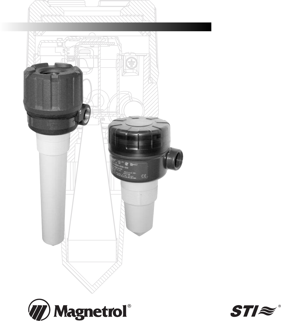
4. Adjust the beam position by turning the internal launcher
adjustment (Fig ??). The internal launcher adjustment is
numbered 1-18 that equates to 10-180 degrees of adjust-
ment; 9 is the midpoint where long axis of the beam is at
45 degrees to the Display (Fig ??). After positioning the
transmitter display, rotate the launcher adjustment so the
beam is at an angle of 45° to a line from the radar unit to
the nearest tank wall (Fig ??). Do not optimize the Quality
(signal strength) at one level in the vessel.
• Do not place insulating material around any part of the
Radar transmitter including the antenna process connection.
1.3 QuickStart Wiring
NOTE: Make sure the electrical wiring to the R82 radar transmitter is
complete and in compliance with all regulations and codes.
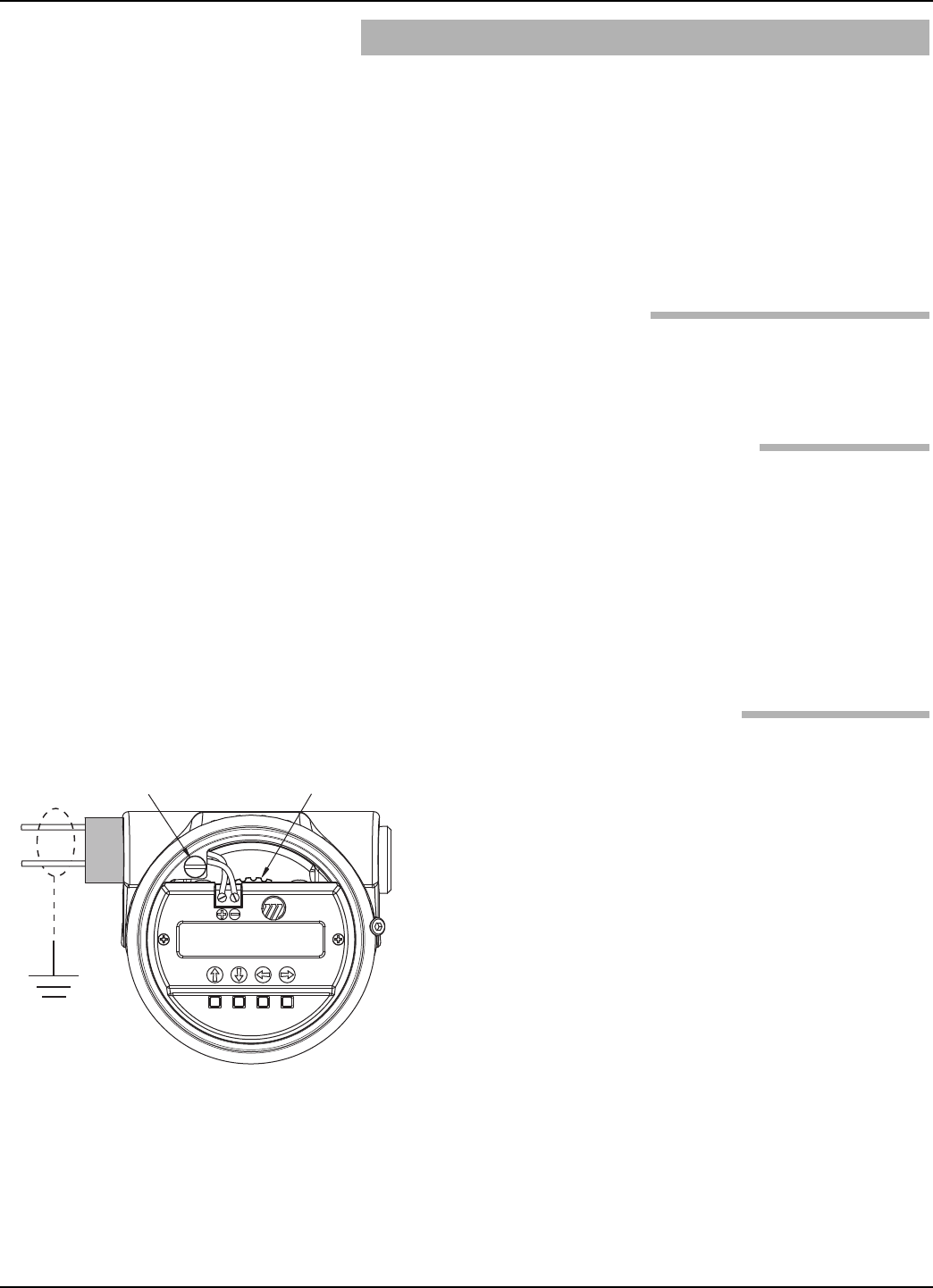
1. Remove the cover of the wiring compartment.
2. Attach a conduit fitting and mount the conduit plug in the
spare opening. Pull the power supply wire through the con-
duit fitting.
3. Connect shield to an earth ground at power supply and
leave floating at the transmitter.
4. Connect the positive supply wire to the (+) terminal and the
negative supply wire to the (-) terminal. For Explosion
Proof Installations, see Wiring, Section 2.5.3.
5. Replace the cover and tighten.
58-610 Model R82 Radar Transmitter
Figure X
Beam Orientation with #9
Launcher Position
Ground
Launcher Adjustment
(with #9 Position Selected)
45°
(+)
(-)
7
58-610 Model R82 Radar Transmitter
Ground
Launcher
Adjustment
(+)
(-)
1.4 QuickStart Configuration
The Radar transmitter comes factory-calibrated and can be
configured in minutes for specific applications. Bench con-
figuration provides a convenient and efficient way to set up
the transmitter before going to the tank site to complete the
installation. The minimum configuration instructions fol-
low. Use the information from the operating parameters
table before beginning configuration. See Configuration
Information, Section 1.1.2.
1. Power-up the transmitter.
During normal operation the display changes every 3 sec-
onds to show one of the various measured values that can be
chosen for display: Level, Volume, Distance, Echo Strength,
%Output, Loop Current and Local Tag.
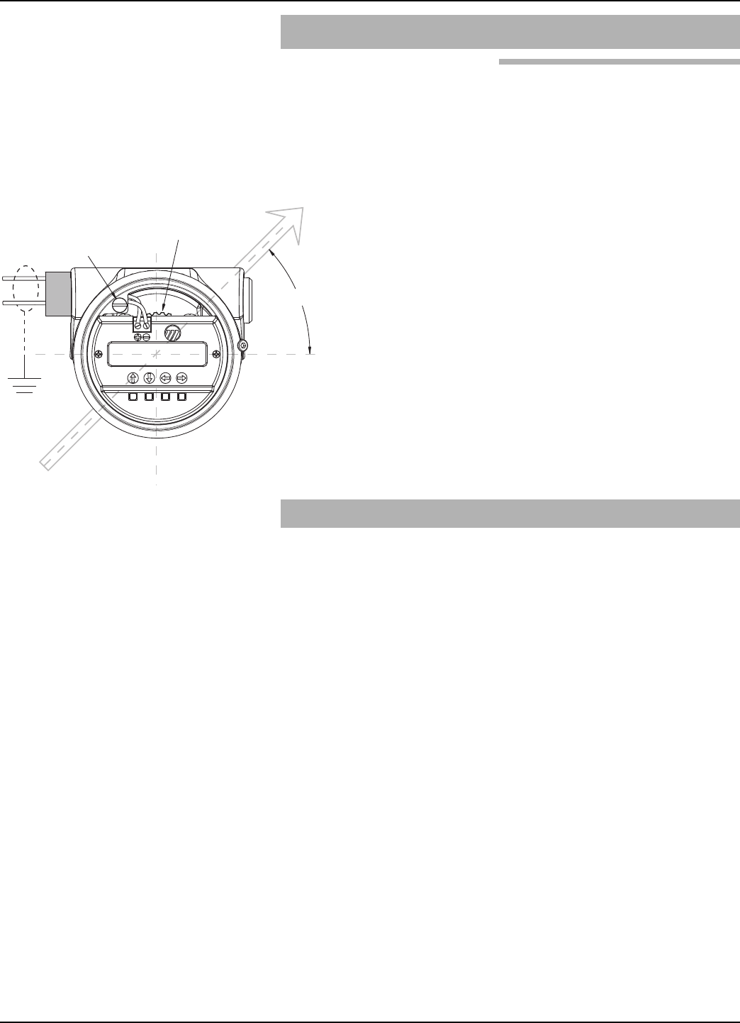
2. Remove the cover of the electronic compartment.
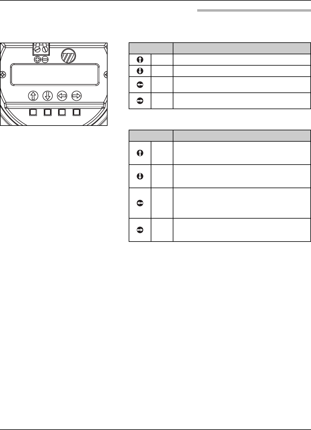
3. The Pushbuttons offer multiple forms of functionality for
menu navigation and data entry. (See Section 2.6.3???? for
complete explanation)
UP arrow moves up through menu or increases dis-
played value
DOWN arrow moves down through menu or decreases
displayed value
BACK arrow exits a branch of the menu or exits with-
out accepting entered value
ENTER arrow enters a branch of the menu or accepts
entered value
If a PASSWORD is requested, enter it now. The Default=0
(no password necessary). The last character in the first
line of the display changes to an exclamation point (!).
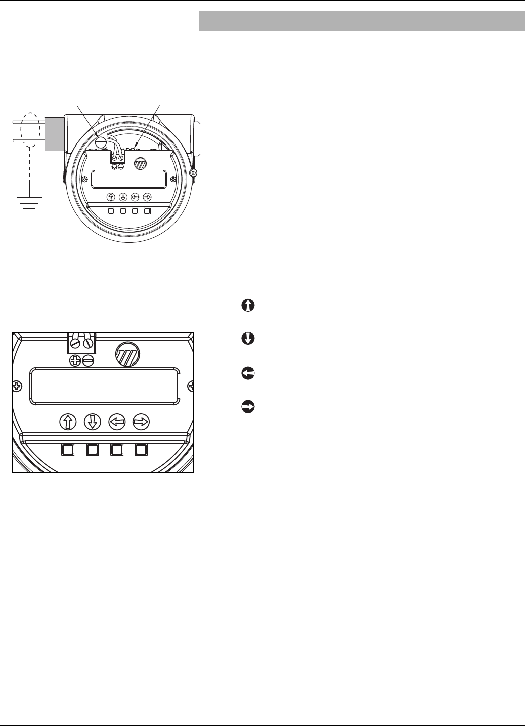
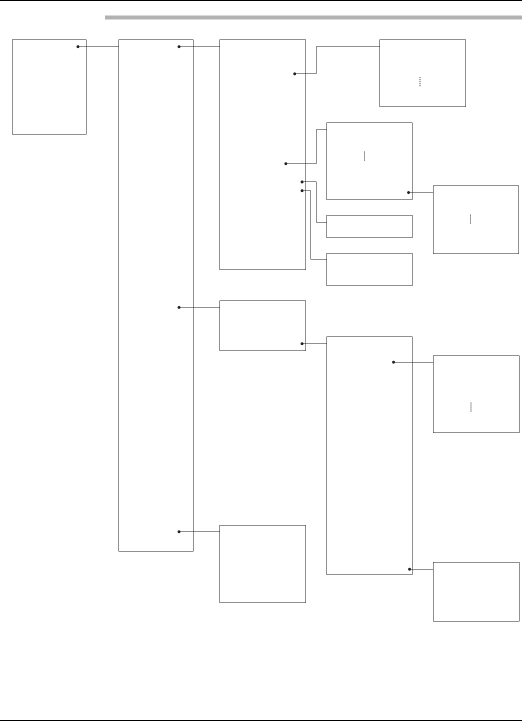
858-610 Model R82 Radar Transmitter
Select if Level or Level & Volume
Select the Units of measure for the
display (cm, inches, meters, feet).
Enter the Sensor Offset value; the
distance from the top (100%) point of
the vessel to the Sensor Reference
point (bottom of an NPT thread, top
of a BSP thread, face of a flange).
Select the type of Tank Top; choices
are Flat, Horizontal cylinder, Dome,
Irregular, or Other (nonmetallic).
Enter the exact Tank Height; inaccu-
rate values will create inaccurate level
readings.
Enter the Blocking Distance; the
distance close to the antenna where
measurement is unreliable. Minimum
value = 15" (375 mm)???? as meas-
ured from the process connection.
Enter the Level Offset; the distance
at the bottom of the vessel where
measurement may be unreliable due
to heating coils, irregular bottom, etc.
Select the proper Dielectric range for
the process medium.
Select the value of Turbulence that
corresponds to the application.
Select the Foam value that corre-
sponds to the application.
Select the Rate of Change value that
corresponds to the maximum rate the
level will rise or fall.
Examine the list of reflections detect-
ed by the transmitter to ensure the
actual level reflection is present. It
may be necessary to rotate the
launcher for optimal performance.
Run the Echo Rejection routine by
choosing the correct LEVEL thereby
cancelling all false reflections in the
vessel; ideally with tank empty.
Enter the minimum level value (0%)
for the 4 mA point.
Enter the maximum level (100%) for
the 20 mA point.
Measure
Type
Level Units
(select)
Sensor Offset
xxxx
Tank Top
(select)
Tank Height
xxxx
Blocking Dist
xxxx
Level Offset
xxx.x
Dielectric
(select)
Turbulence
(select)
Foam
(select)
Rate of Change
(select)
Set 4mA
xx.x
Echo Profile
Set 20mA
xx.x
Sensor Offset
Tank Height
Blocking
Distance
Level
Offset
2
1
7
8
911
10
12
13
14
5
3
64
The following configuration entries are the minimum
required for configuration. The default password is 0.
1
2
3
4
5
6
8
9
10
11
12
13
14
7
9
58-610 Model R82 Radar Transmitter
2.0 Complete Installation
This section provides detailed procedures for properly
installing, configuring, and, as needed, troubleshooting the
R82 Radar Level Transmitter.
2.1 Unpacking
Unpack the instrument carefully. Make sure all components
have been removed from the packing material. Check all the
contents against the packing slip and report any discrepancies
to the factory.
Before proceeding with the installation, do the following:
• Inspect all components for damage. Report any damage to
the carrier within 24 hours.
• Make sure the nameplate model number on the transmitter
agree with the packing slip and purchase order.
• Record the model and serial numbers for future reference
when ordering parts.
2.2 Electrostatic Discharge (ESD)
Handling Procedure
Magnetrol’s electronic instruments are manufactured to the
highest quality standards. These instruments use electronic
components that may be damaged by static electricity pres-
ent in most work environments.
The following steps are recommended to reduce the risk of
component failure due to electrostatic discharge.
• Ship and store circuit boards in anti-static bags. If an anti-
static bag is not available, wrap the board in aluminum foil.
Do not place boards on foam packing materials.
• Use a grounding wrist strap when installing and removing
circuit boards. A grounded workstation is recommended.
• Handle circuit boards only by the edges. Do not touch
components or connector pins.
• Make sure that all electrical connections are completely
made and none are partial or floating. Ground all equip-
ment to a good, earth ground.
10
2.3 Before You Begin
2.3.1 Site Preparation
Each R82 Radar transmitter is built to match the specific
physical specifications of the required installation. Make
sure the antenna connection is correct for the threaded or
flanged mounting on the vessel or tank where the transmit-
ter will be placed. See Mounting, Section 2.4.
Make sure that the wiring between the power supply and
Radar transmitter are complete and correct for the type of
installation.
When installing the Radar transmitter in a general purpose
or hazardous area, all local, state, and federal regulations and
guidelines must be observed. See Wiring, Section 2.5.
2.3.2 Equipment and Tools
No special tools are needed. The following items are
recommended:
• Threaded antenna and transmitter . . . . . . 2" (50 mm)
• Torque wrench . . . . . . . . . . . . . . . . . . . . . highly desirable
• Flat-blade screwdriver
• Digital multimeter or volt/ammeter . . . . . Optional
• 24 VDC (23 mA) power supply. . . . . . . . Optional
2.3.3 Operational Considerations
Radar applications are characterized by three basic conditions;
Dielectric, Distance (measuring range) and Disturbances
(turbulence, foam, false targets, multiple reflections and rate
of change).
2.3.3.1 Maximum Distance
The chart below shows the maximum measuring range
(Distance) of each antenna based on fundamental condi-
tions of Dielectric, Distance and Turbulence. Maximum dis-
tance is calculated as Tank Height + Sensor Offset
(see page 17). It is measured from the Sensor Reference
Point (bottom of NPT thread, top of BSP thread or face of
a flange).
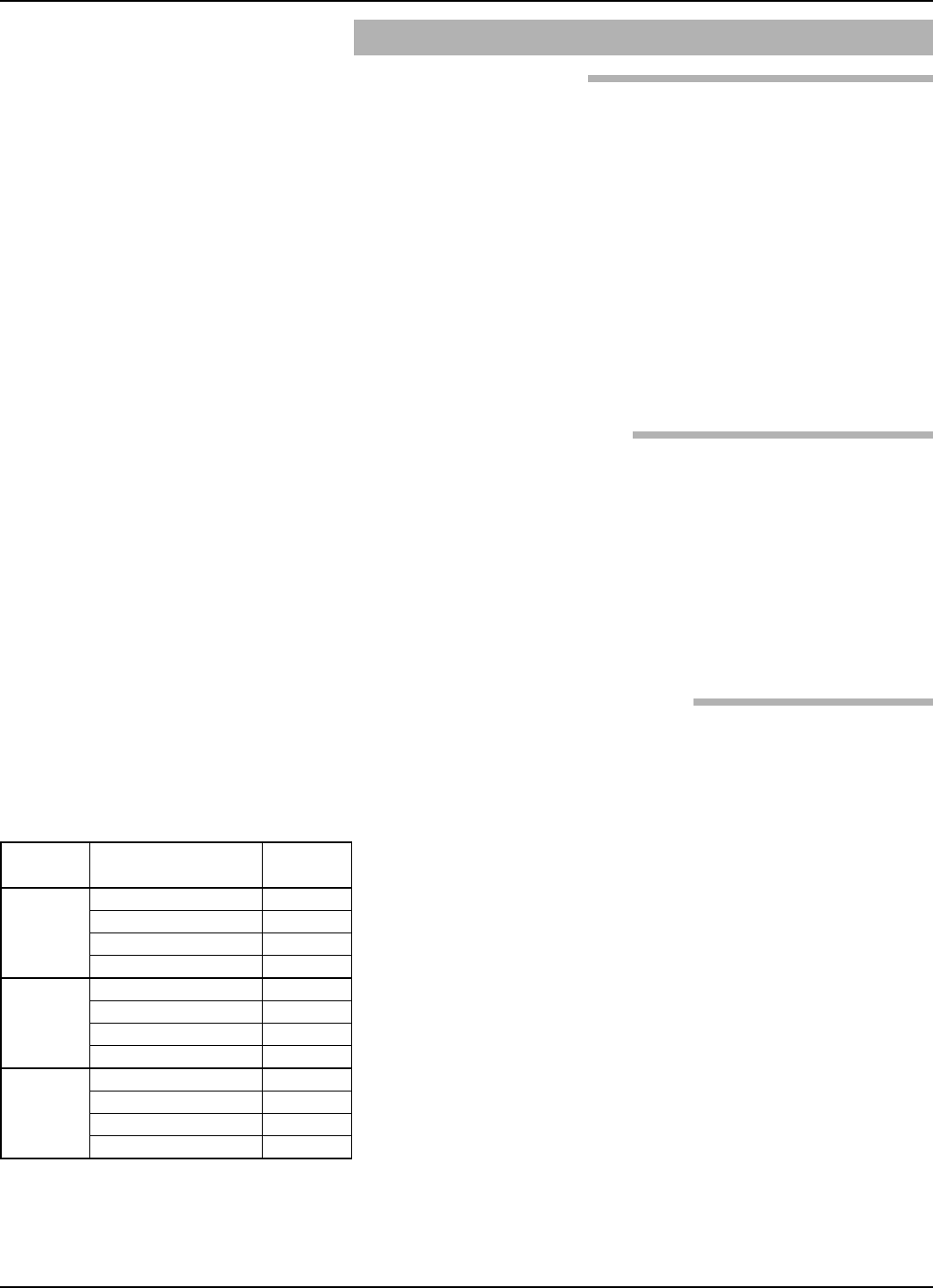
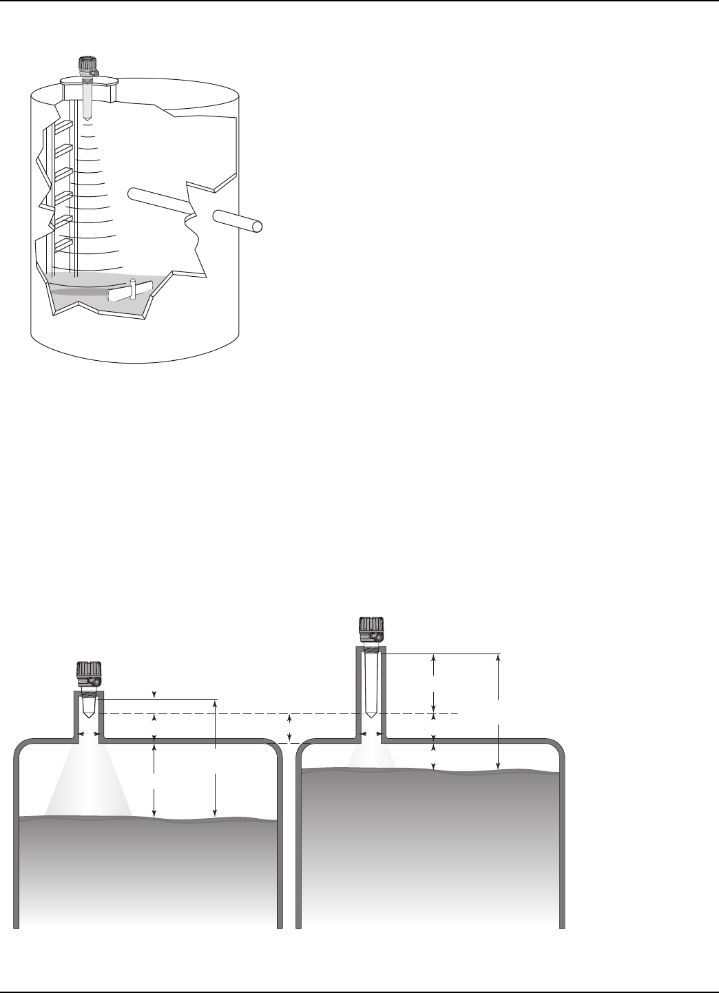
2.3.3.2 Minimum Distance
If the liquid level is allowed onto the antenna, noise and
media build-up drastically decrease reliable measurement.
Liquid should not be allowed closer than 15 inches
(380 mm) from the bottom of the antenna mounting
threads (or face of sanitary flange).
58-610 Model R82 Radar Transmitter
Dielectric Turbulence R82
1.7-3.0
None 26 (8.0)
Light, < 0.5" 21 (6.4)
Moderate, < 1.0" 14 (4.3)
Heavy, > 1.0" 7 (2.1)
3.0-10.0
None 33 (10.1)
Light, < 0.5" 26 (7.9)
Moderate, < 1.0" 19 (5.8)
Heavy, > 1.0" 12 (3.7)
10.0-100
None 40 (12)
Light, < 0.5" 32 (9.8)
Moderate, < 1.0" 24 (7.3)
Heavy, > 1.0" 17 (5.2)
MAXIMUM DISTANCE feet (meters)
11
58-610 Model R82 Radar Transmitter
2.3.3.3 Problematic Applications; GWR Alternative
Some application concerns can be problematic for Radar.
For these, Guided Wave Radar is recommended:
• Extremely low dielectric media (εr<2.0)
• Very weak reflections from the liquid surface, particularly
during turbulence, can cause poor performance.
• Tanks heavily cluttered with false targets (mixers, pumps,
ladders, pipes, etc.)
• During times of very low liquid levels of low dielectric media,
the metal tank bottom may be detected deteriorating per-
formance.
2-inch (50 mm) Antenna 8-inch (200 mm) Antenna
13"
(330 mm)
7"
(178 mm)
15" (380 mm) Minimum
(measured from
bottom of threads or
flange face)
2-inch (50 mm)
Antenna
Maximum Recess (m) is 2 ×Nozzle Diameter (d)
(example: 2" diameter nozzle)
8-inch (200 mm)
Antenna
Maximum
Liquid Level
Maximum
Liquid Level
m
d
15"
(380 mm)
2" (50 mm)
4" (100 mm)
15"
(380 mm)
8" (200 mm)
9" (225 mm)
3" (75 mm)
4" (100 mm)
d
Figure X
<Caption>
Figure X
<Caption>
12 58-610 Model R82 Radar Transmitter
• Foam can either absorb or reflect the microwave energy
depending upon the depth, dielectric, density and wall
thickness of the bubbles. Due to typical variations in the
amount (depth) of foam, it is impossible to quantify per-
formance. It may be possible to receive most, some or none
of the transmitted energy.
• Extremely high liquid levels (Overflow) conditions when
liquid very near the antenna can cause erroneous readings
and measurement failure.
2.4 Mounting
The R82 Radar transmitter can be mounted to a vessel
using a variety of process connections. Generally, either a
threaded or flanged connection is used.
2.4.1 Installing the Antenna
Before installing, make sure:
• Process temperature, pressure, dielectric, turbulence and
distance are within the antenna specifications for the
installation.
• End of antenna is protected from bending or breaking.
• Insulating material is not placed around any part of the
Radar transmitter including the antenna flange.
• Antenna is being mounted in the optimal location. See fol-
lowing sections: Location, Beam Angle, Obstructions and
Nozzles for specific information.
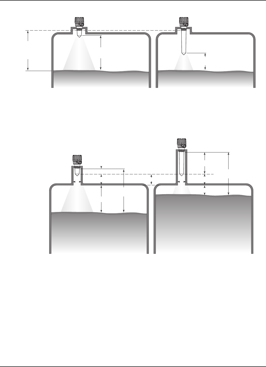
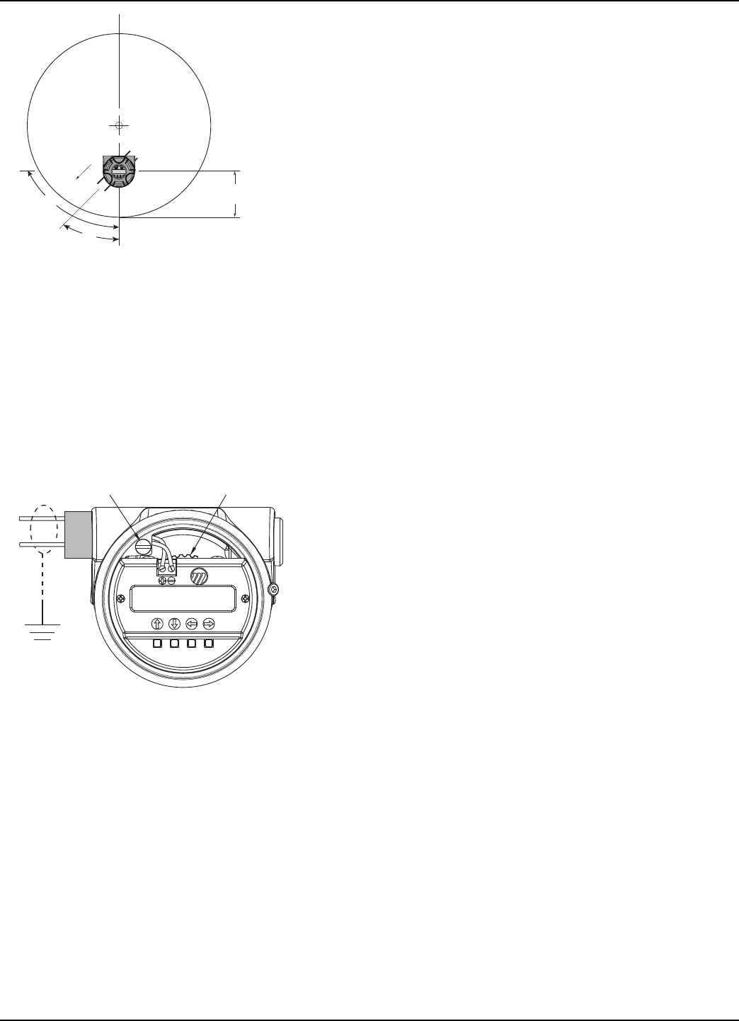
2.4.1.1 Location
Ideally, the Radar transmitter should be mounted providing
an unobstructed signal path to the liquid surface where it
should illuminate (with microwave energy) the largest,
possible surface area. See Section 2.4.1.2, Beam Angle.
Unavoidable obstacles will produce reflections that must be
minimized during field configuration. See Section 2.6.5.1,
Target Rejection. Mount in a location equal to 1⁄2the radius
of tank top. Do not mount in center of vessel nor closer
than 10" (25 cm) of tank wall.
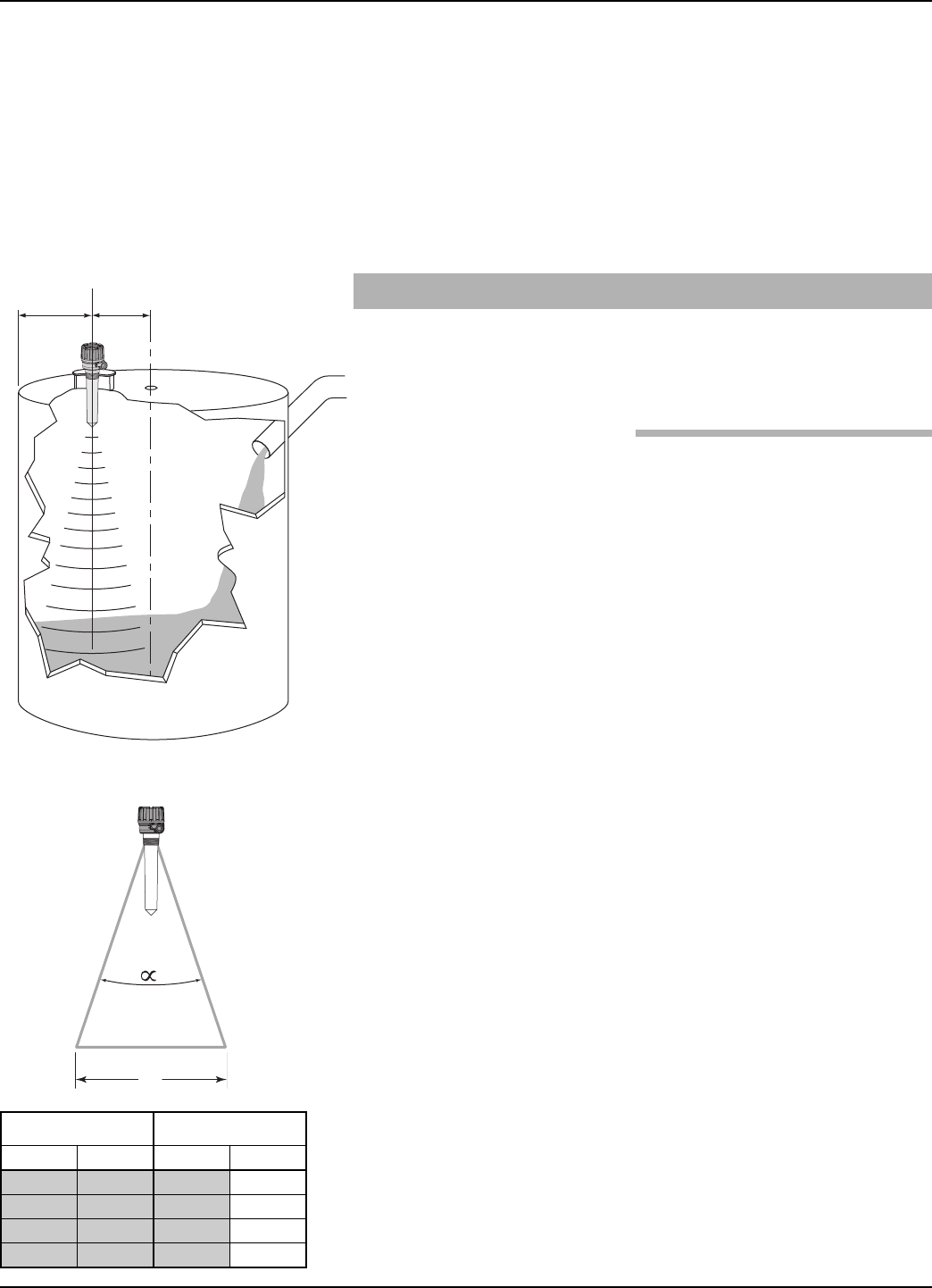
2.4.1.2 Beam Angle
The various antenna designs exhibit different beam patterns.
Ideally, the beam pattern should illuminate the maximum
liquid surface with a minimum striking other objects in the
vessel including the tank wall. Use these drawings to deter-
mine the optimum installation location.
1/2
Radius
> 10"
(25 cm)
W
Distance Beam Spread
Feet Meters Feet Meters
10 3 1.7 0.52
20 6 3.5 1.05
30 9 5.2 1.57
40 12 7.0 2.10
13
58-610 Model R82 Radar Transmitter
2.4.1.3 Obstructions
Almost any object that falls within the beam pattern will
cause reflections that may be misinterpreted as a false liquid
level. Although Model R82 has a powerful False Target
Rejection routine, all possible precautions should be taken
to minimize false target reflections with proper installation
and orientation.
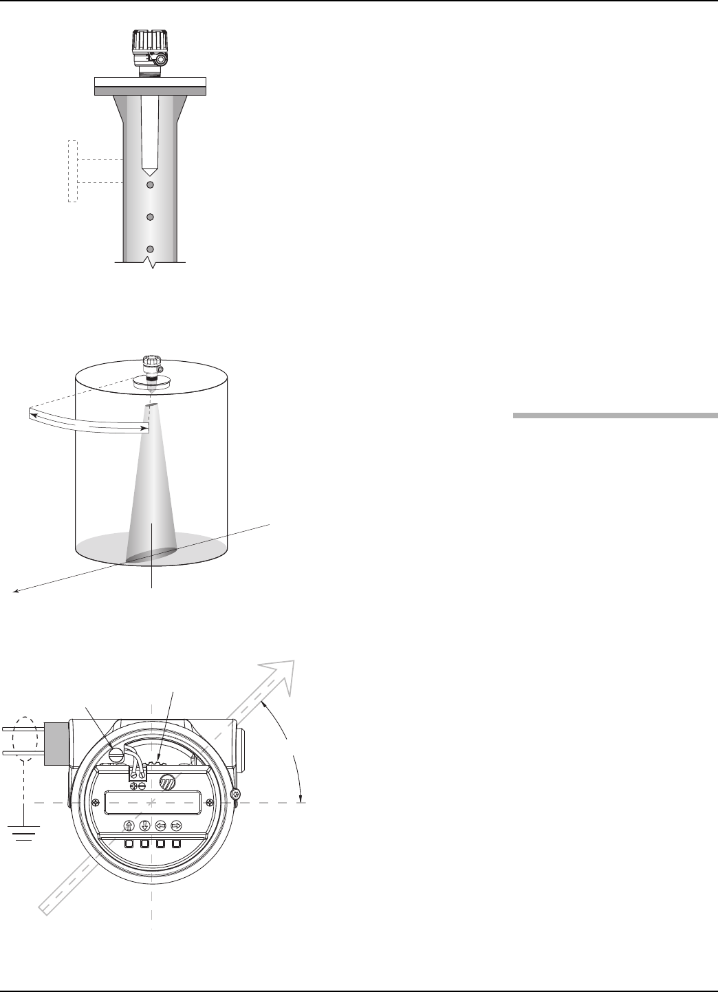
2.4.1.4 Nozzles
Improper installation in a nozzle creates “ringing” which
will adversely affect measurement. Refer to Figure 9???. Two
Antenna extension lengths are offered to allow the R82
transmitter to work reliably in a variety of nozzles.
The Minimum Blocking Distance of 15" (380 mm) is
always measured from the bottom of the threads or face of
a flange. The related distance as measured from the end of
the antenna varies depending on the antenna extension
chosen. See Figure ??.
The narrow beam width of the 26 GHz, R82 does allow
mounting so that the antenna can be recessed inside the
nozzle. Optimally, the recessed dimension should never
exceed 2×the nozzle diameter. See Figure??????
NOTE: If the antenna is recessed in a nozzle it is mandatory that Echo
Rejection is run to eliminate any possibility of false reflections.
2-inch (50 mm)
Antenna
Maximum Recess (m) is 2 ×Nozzle Diameter (d)
(example: 2" diameter nozzle)
8-inch (200 mm)
Antenna
Maximum
Liquid Level
Maximum
Liquid Level
m
d
15"
(380 mm)
2" (50 mm)
4" (100 mm)
15"
(380 mm)
8" (200 mm)
9" (225 mm)
3" (75 mm)
4" (100 mm)
d
14 58-610 Model R82 Radar Transmitter
2.4.1.5 Standpipes and Stillwells
The R82 can be mounted in a standpipe or stillwell but
certain considerations should be given:
• Metal stillwells only: 2" (Sched 40 max.) to 4" (50–100 mm).
• Diameter must be consistent throughout length; no reducers.
• Stillwell length must cover complete range of measurement
(i.e., liquid must be in stillwell).
• Welds should be smooth.
• Vents: holes <0.125" diameter, slots <0.125" width.
• If an isolation valve is used, it must be a full port ball valve
with an I.D. equal to the pipe diameter.
• Bridles/Bypass Installations: The launcher should be rotated
90° from process connections.
• Configuration must include an entry for PIPE I.D.
See Section 2.6.5.1, Item 34- PIPE I.D.
• There will be some increased dielectric sensitivity; system
GAIN will be reduced when PIPE ID >0.
2.4.2 Installing the Transmitter
Install the Transmitter with its integral antenna by threading
into the vessel. DO NOT OVERTIGHTHEN as this may
cause damage to the plastic threads.
• Do not place insulating material around any part of the
radar transmitter including the antenna flange.
• Installation for NEMA 6P/IP 68- the transmitter can be
installed to allow for temporary submergence to 6 feet (1.8m):
- use TFE paste to seal conduit entries and antenna process
connection
- Do not overtighten housing cover; O-ring develops
water-tight seal without excessive tightening
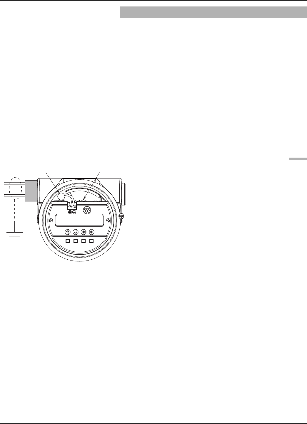
2.4.2.1 Orientation
The R82 transmitter utilizes a linearly polarized, microwave
beam that can be rotated to improve its performance. Proper
orientation can minimize unwanted target reflections, decrease
sidewall reflections (multipath) and maximize direct reflec-
tions from the liquid surface.
The internal launcher mechanism can be turned to optimize
performance. The launcher has index marks numbered
1–18 (representing 10–180 degrees). The Polarization
pattern is at 45 degrees to the transmitter display when
the mechanism is at the #9 position.
Figure X
Beam Orientation with #9
Launcher Position
Figure X
R82 Mounted in Stillwell (Bridle)
Ground
Launcher Adjustment
(with #9 Position Selected)
45°
(+)
(-)
45°
Figure X
Polarization Pattern
15
58-610 Model R82 Radar Transmitter
2.4.2.2 Initial Installation
Ideally, the transmitter should be mounted half the radius
from the tank wall. In a typical vertical tank, the Launcher
should be adjusted so the polarization pattern is 45 degrees
to the closest tank sidewall. See Figures ? & ?.
For horizontal cylindrical vessels, aim beam down the long
axis of the vessel. Do not optimize the Quality (signal
strength) at one level in the vessel.
A transmitter mounted within 10" (25 cm) of a tank wall
may demand orientation adjustments to limit multipath
and optimize performance. See Section 2.4.2.3, Poor Echo
Strength.
2.4.2.3 Poor Echo Strength
Poor signal quality has many potential causes. Following are
two initial areas for investigation.
Launcher Orientation: Initial launcher orientation is always
45 degrees (see Sections 2.4.1 & 2.4.2). In tall vessels and
when antenna is mounted close to the tank wall, improve-
ment in signal quality may be attained by rotating the
launcher to 90 degrees.
Signal Loss: If the Level signal is lost repeatedly at a specific
point in the vessel, it is usually a symptom that multipath
(side-wall reflections) are causing cancellation by returning
to the transmitter exactly 180° out of phase with the Level
signal. Utilize the following procedure:
• Go to transmitter screen #5 which shows both Level and
Echo Strength.
• Bring the Level up (or down) to the exact point where the
signal is repeatedly lost. Monitor the Echo Strength this
point is being approached. The Echo Strength will degrade
to a low point before it begins to increase.
• At the poorest Echo Strength slowly rotate the launcher
1–2 notches. Allow the unit to stabilize for approximately
one minute. Repeat this process until the Echo Strength is
optimized.
1/2 Radius
Orientation
Mechanism
in #9position
45°
90°
Figure X
Top View
Mounted 1⁄2radius
Figure X
xxxx
Ground
Launcher
Adjustment
(+)
(-)
16 58-610 Model R82 Radar Transmitter
2.5 Wiring
Caution The R82 Radar transmitter operates at voltages of 16–36
VDC (GP) and 16-28.6 VDC (IS). Higher voltage will dam-
age the transmitter.
Wiring between the power supply and the Radar transmitter
should be made using 18–22 AWG shielded twisted pair
instrument cable. Within the transmitter enclosure, con-
nections are made to the terminal strip and the ground
connections. Trim excess wiring to minimize clutter, noise
issues and allow access to Launcher adjustment (see
Figure ??). The directions for wiring the Radar transmitter
depend on the application:
• General Purpose or Non-incendive (Cl I, Div. 2)
• Intrinsically Safe
NOTE: For ATEX installation guidelines refer to bulletin BE 58-610.
2.5.1 General Purpose or Non-incendive (Cl I, Div. 2)
A general purpose installation does not have flammable
media present. Areas rated non-incendive (Cl I, Div. 2) have
flammable media present only under abnormal conditions.
No special electrical connections are required. If flammable
media is contained in the vessel, the transmitter must be
installed per Cl I, Div. 1 standards of area classification.
To install General Purpose or Non-incendive wiring:
1. Remove the cover to the wiring compartment of the trans-
mitter. Install the conduit plug in the unused opening.
2. Install a conduit fitting and pull the supply wires.
3. Connect shield to an earth ground at power supply and
leave floating at the transmitter.
4. Connect an earth ground wire to the nearest green ground
screw per local electrical code (not shown in illustration).
5. Connect the positive supply wire to the (+) terminal and
the negative supply wire to the (-) terminal.
6. Replace cover to the wiring compartment of transmitter.
Ground
Launcher
Adjustment
(+)
(-)
Figure X
xxxx
17
58-610 Model R82 Radar Transmitter
2.6 Configuring the Transmitter
The Radar transmitter comes factory-calibrated and can be
configured in minutes for specific applications.
Before configuring the transmitter, collect the operating
parameters information. Then, power-up the transmitter
on the bench and follow through the step-by-step proce-
dures for the menu-driven transmitter display. Information
on configuring the transmitter using a HART communica-
tor is given in Configuration Using HART (Section 2.7).
2.6.1 Operating Parameters
Some key information is needed to configure the Radar
transmitter. If necessary, complete the configuration infor-
mation table in Section 1.1.2.
2.6.2 Setting Up for Shop Configuration
The Radar transmitter can be configured at a test bench by
connecting a 24 VDC power supply directly to the trans-
mitter terminals. The connections are illustrated in the
accompanying diagrams. An optional digital multimeter is
shown if current measurements are desired.
When using a HART communicator for configuration, a
minimum 250 Ωline load resistance is required. See the
HART communicator manual for more information.
2.6.3 Transmitter Display and Keypad
The R82 transmitter has a local user interface consisting of
a 2-line by 16-character liquid-crystal display (LCD) and
4-push-button keypad. All transmitter measurement data
and configuration information is shown in the LCD.
The transmitter default display is the measurement screen.
It cycles every 5 seconds to display *STATUS*, *LEVEL*,
*ECHO STRENGTH*, *%OUTPUT*, *LOOP CUR-
RENT* and *LOCAL TAG* information. The transmit-
ter defaults to this display after 5 minutes if no keystrokes
are sensed. You can also access each of these screens indi-
vidually. The display will not return to the default screen
if left in one of these screens. For example, the device can
be left to read only LEVEL indefinitely if left in this
screen.
Ground
Launcher
Adjustment
(+)
(-)
Figure X
xxxx
2.6.4 Menu Traversal
The push buttons offer multiple forms of functionality
18 58-610 Model R82 Radar Transmitter
Push button Keystroke Action
Up Moves to the previous item in the menu branch
Down Moves to the next item in the menu branch
Back Moves back one level to the previous higher
branch item
Enter Enters into the lower level branch or switches to
the entry mode
Push button Keystroke Action
Up
Moves to the previous character (Z,Y,X,W). If held
down the characters scroll until the push button
is released.
Down
Moves to the next item character (A,B,C,D). If
held down the characters scroll until the push
button is released.
Back
Moves the cursor back to the left. If the cursor is
already at the leftmost position, then the screen
is exited without changing the original tag
characters.
Enter
Moves the cursor forward to the right. If the
cursor is at the rightmost position, then the
new tag is saved.
2.6.4.1 Navigating Menu
2.6.4.2 Entering Character Data
19
58-610 Model R82 Radar Transmitter
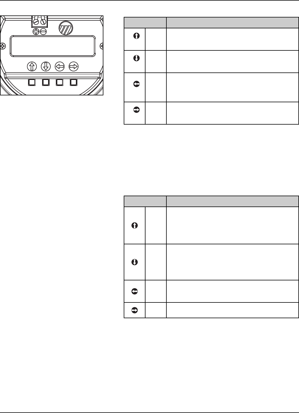
NOTES: All numeric values are left-justified, and new values are
entered from left to right. A decimal point can be entered after
the first digit is entered, such that .9 is entered as 0.9.
A few configuration items can have a negative value. In this
case, the leftmost position is reserved for the sign (either “-“
for a negative value, or “+” for a positive value)
Push button Keystroke Action
Up
Moves up to the next highest digit (0,1,2,3,....,9).
If held down the digits scroll until the push button
is released.
Down
Moves down to the next lowest digit
(9,8,7,6,….,0). If held down the digits scroll until
the push button is released.
Back
Moves the cursor to the left and deletes a digit. If
the cursor is already at the leftmost position,
then the screen is exited without changing the
previously saved value.
Enter
Moves the cursor to the right. If the cursor is
located at a blank character position, the new
value is saved.
Push button Keystroke Action
Up
Increments the displayed value. If held down the
digits scroll until the push button is released.
Depending on which screen is being revised, the
increment amount may increase by a factor of 10
after the value has been incremented 10 times.
Down
Decrements the displayed value. If held down the
digits scroll until the push button is released.
Depending on which screen is being revised, the
decrement amount may increase by a factor of 10
after the value has been decremented 10 times.
Back
Returns to the previous menu without changing
the original value, which is immediately redis-
played.
Enter Accepts the displayed value and returns to the
previous menu.
2.6.4.3 Entering numeric data using Digit Entry
2.6.4.4 Entering numeric data using Increment/Decrement

20 58-610 Model R82 Radar Transmitter
2.6.5 Password Protection (Default = 0)
The Radar transmitter is password protected to restrict
access to certain portions of the menu structure that affect
the operation of the system. When the proper password is
entered, an exclamation point (!) appears as the last charac-
ter of the first line of the display. The password can be
changed to any numerical value up to 255. The password
is required whenever configuration values are changed.
The default password installed in the transmitter at the fac-
tory is 0 (password disabled). The last step in the configura-
tion menu provides the option to enter a new password. If
0 is entered as a password, the transmitter is no longer pass-
word protected and any value in the menu can be altered
(except diagnostic values) without entering a confirming
password.
NOTE: If the password is not known, the menu item New Password
(Section 2.6.6.1, item #39) displays an encrypted value repre-
senting the present password. Call the factory with this
encrypted value to determine the actual password.
21
58-610 Model R82 Radar Transmitter
2.6.6 Menu: Step-By-Step Procedure
The following table provides a complete explanation of the
software menus displayed by the Radar transmitter. Use this
table as a step-by-step guide to configure the transmitter.
The first column presents the menus shown on the trans-
mitter display. The displays are in the order they would
appear if the arrow keys were used to scroll through the
menu. The numbers are not shown on the display. They
are provided as a reference only.
The second column provides the actions to take when
configuring the transmitter. Additional information or an
explanation of an action is given in the third column.
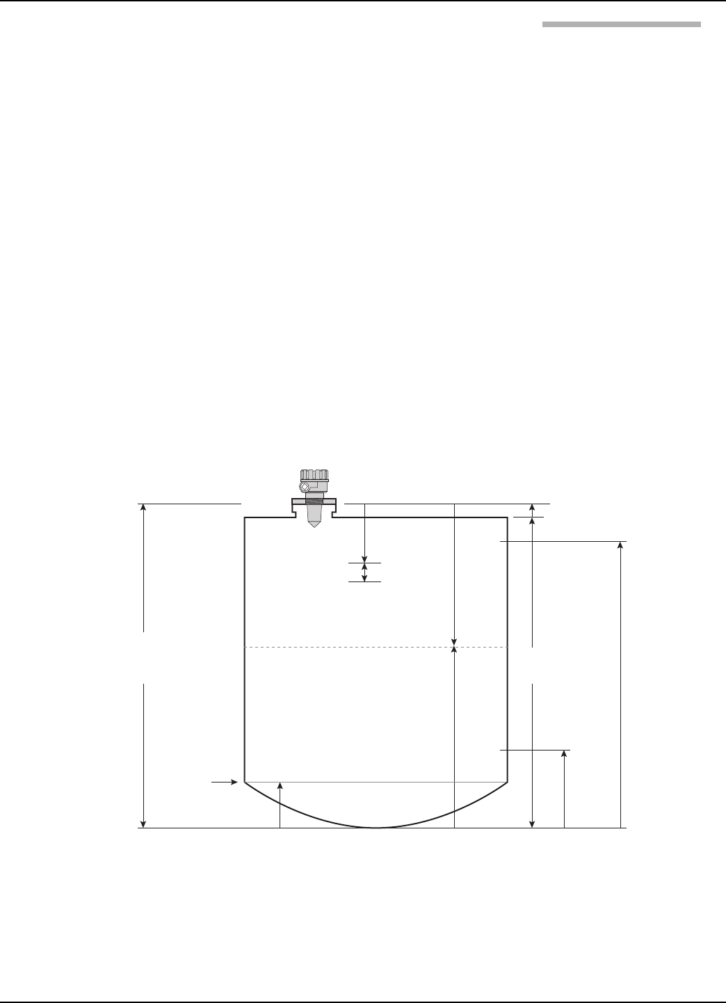
The following drawings are provided as reference for the
configuration procedure.
Use of the included PACTware™PC program is highly
recommended and invaluable for troubleshooting and
advanced calibration. A HART RS232 or USB modem
(purchased separately) is required. See Magnetrol
PACTware™bulletin 59-101.
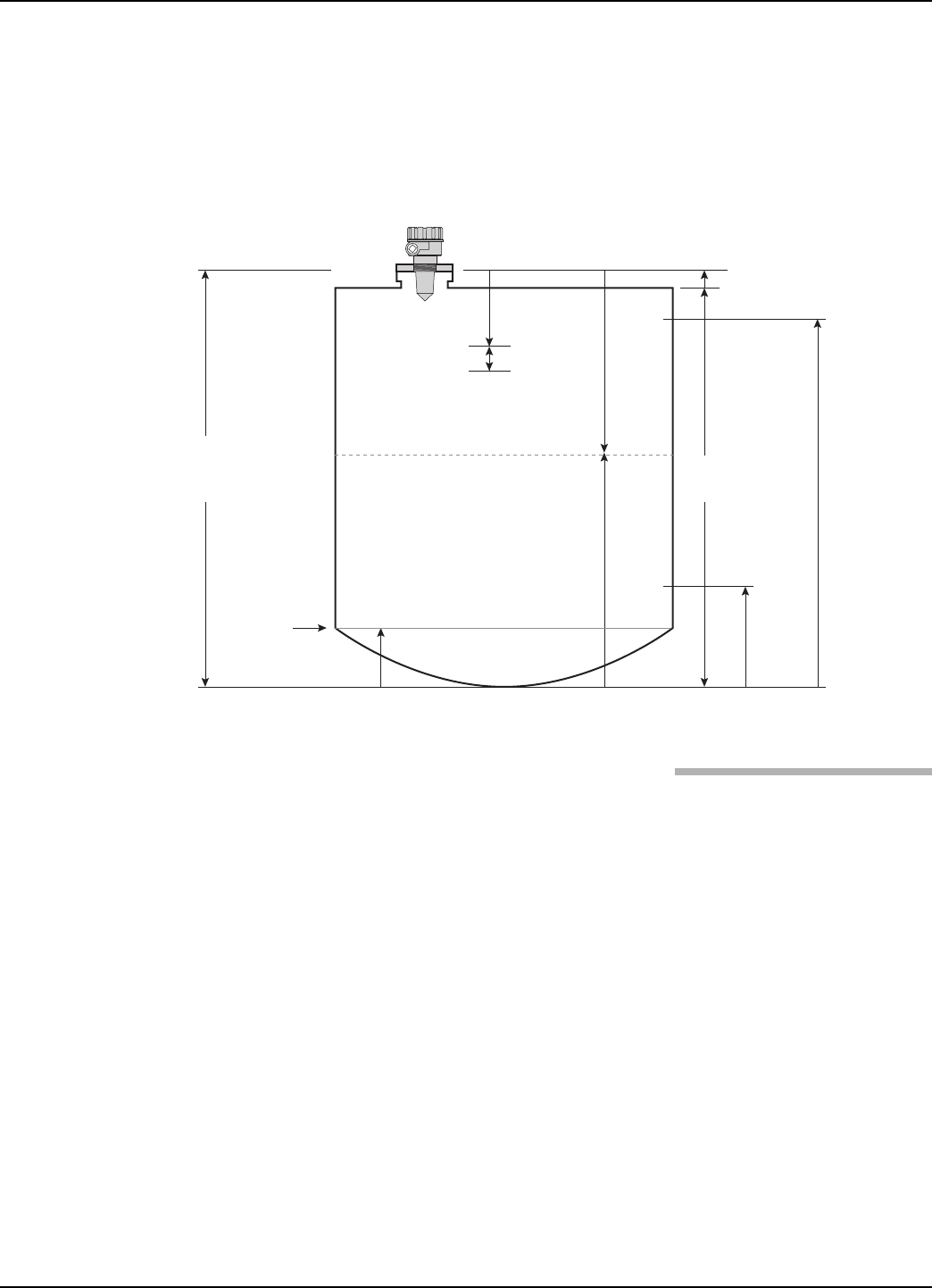
Tank
Height
Sensor Offset + Tank Height =
Distance from process
connection to tank bottom
20 mA
4 mA
Sensor Reference Point
Sensor Offset (+)
Blocking
Distance
Distance
Safe Zone
Media
Level
Level Offset
Lowest
Measurable
Value

22 58-610 Model R82 Radar Transmitter
2.6.6.1 Radar Transmitter User Menu
Note: Press UP arrow 5 times to reach screen where menu language can be chosen.
Display Action Comment
1
*Status*
*Level*
*Volume*
*Distance*
*Echo Str xx*
*%Output*
*Loop Current*
*Local Tag*
Transmitter Display
Transmitter default display: Status, Level, Volume (if chosen)
Echo Strength, % Output, Loop Current and Local Tag values
cycle every 5 seconds. All screens (except 2-8) default to this
screen after 5 minutes of no keystrokes or if a Fault or Warning
message is displayed.
Default display will show the highest priority Fault or Warning (or
OK if no current messages). If more than one Fault or Warning
exists they will be displayed in the History screen (#46) in
chronological order.
To Add/Remove what information is shown in default display:
• Go to specific parameter in question (screens 2-8)
• Press Enter
• Choose On or Off
• Press Enter to confirm
2Level
xxx.x units Transmitter Display Transmitter displays Level measurement in chosen unit of
measure.
3Volume
xxx.x units Transmitter Display Transmitter displays Volume measurement in chosen unit of
measure (if chosen)
4Distance
xxx.x units Transmitter Display
Transmitter displays Distance measurement in chosen unit of
measure; measurement includes Sensor Offset value. This value
may not represent reciprocal of Level if the liquid level is within
the Blocking Distance or Level Offset where the Level value is
clamped.
5Echo Strength xx
xxx.x units Transmitter Display Transmitter display showing Level and Echo Strength of signal
reflection. Good values are 20-99.
6% Output
xx.x% Transmitter Display Transmitter displays % Output measurement derived from
20 mA span.
7Loop Current
xx.xx mA Transmitter Display Transmitter displays Loop Current value (mA).
8Local Tag
xxxxxxxxxxxx Transmitter Display Transmitter displays Local Tag information.
9Measure Type
(select) Select Type of Measurement
Select Level Only or Level and Volume. Volume, Volume Units,
Loop Control, and Strapping Table screens appear only when
Level & Volume is selected. Note that the Volume screen is
selected for rotation when Measure Type is set to Level &
Volume and is deselected when Measure Type is set to Level
Only.
10 Level Units
(select) Select Units of measure.
Select cm (xxxx), meters (xx.xx), inches (xxx.x), or feet (xx.xx).
Allowable decimal position is controlled; four characters is
maximum reading. Decimal position is controlled by Units and
Tank Height
11 Volume Units
(select)
Select Volume units of
measure.
Select Liters (xxxx) or Gallons (xxxx).
12 Strapping Table
(enter)
Enter Strapping Table
information
Enter up to 20 pairs of data for Level and Volume.
13 Sensor Offset
xx.x units Enter the Sensor Offset value
Sensor Offset is the distance (+ or -) from the Sensor reference
point (bottom of NPT thread or flange face, top of BSP thread)
to the top of the tank.
14 Tank Top
(select)
Enter the shape/type of tank
top
Select the metallic tank top structure Flat, Horizontal Cylinder,
Dome, Irregular, or Other (non-metallic).
15 Tank Height
xxx.xx units Enter the Tank Height. Tank Height is distance from the bottom to the top of the tank.

23
58-610 Model R82 Radar Transmitter
Display Action Comment
16 Blocking Distance
(xxx.x) Enter the Blocking Distance.
Blocking Distance defines an area near the antenna
where reflections can not be measured effectively due to
antenna ringing. It is measured from the Sensor
Reference point. Minimum value is 2î (50mm) minimum
longer than Antenna length; longer lengths are encour-
aged. Output will be held at value corresponding to
Blocking Distance. Do not allow liquid into the Blocking
Distance.
17 Level Offset
(xxx.x units) Enter the Level Offset.
Level Offset defines an area at the bottom of the vessel
where reflections can not be measured effectively due to
angled bottoms, heating coils, reflections from flat metal
tank bottoms in low dielectric applications, etc. It is the
distance from the bottom of the tank to the lowest valid
level reading. Level reading will never be lower than
Level Offset value.
18 Dielectric
(select) Enter the Dielectric range value. 1.7-3.0; 3.0-10.0; 10.0-100.0
19 Turbulence
(select)
Select amount of
Turbulence of the liquid.
None, Light, Medium, Heavy. Increase selection if
Quality value if Echo is often lost or Strength is <20.
20 Foam
(select) Select amount of Foam. None, Light, Medium, Heavy. Increase selection if
Quality value if Echo is often lost or Strength is <20.
21 Rate of Change
(select) Select Rate of Change of the liquid.
Select the maximum rate of change of the level surface,
rising or falling, in inches (cm)/minute; <5 (13), 5-20 (13-
50), 20-60 (50-150), >60 (150)
22 Echo Profile
Press Enter to
- Review all Echoes
- Run a new Echo Rejection Profile
1.) Echo List Mode- Choose to review echoes in
Distance or Level
2.) Review all echoes using UP/DOWN arrows; listed in
descending Level value
3.) To run a new Echo Rejection Profile
a.) Choose the echo that corresponds to the actual
liquid level
b.) Press ENTER and confirm a new Echo Rejection
profile should be run. If necessary, Press ESCAPE
to exit at any time.
NOTES:
- FALSE TARGET REJECTION should run with vessel
at or near empty when all targets are exposed
- Re-run this routine if intial calibration is done with
significant liquid in vessel
- The false target profile will be disabled and this
routine must be re-run if the following parameters
are modified: SENSOR OFFSET, TANK HEIGHT,
BLOCKING DISTANCE, DIELECTRIC,
TURBULENCE, FOAM
- The NO FALSE TARGET REJECTION message will
be displayed if this algorithm is DISABLED.
continued on next page

24 58-610 Model R82 Radar Transmitter
Display Action Comment
22 Echo Profile
(cont.)
- Review an existing Echo
Rejection Profile
continued from previous page
4.) Enter Level- use this entry to manually enter the
correct level value
Error messages:
"Echo to Close" indicates the liquid is too close to the antenna.
Liquid should not be closer than 30" (750 mm).
"Echo to High" indicates an echo being rejected is too large.
a.) Ensure it is not the actual liquid level
b.) Rotate the Launcher to minimize the echo
5.) Saved Echo Rejection Profile-
a.) Enable or Disable an existing profile
b.) Review Echoes from an existing profile
c.) Review Level value where existing profile was run
23 Loop Control
(select) Select mode for Loop Control Select Level or Volume.
24 4 mA Set Point
(xxx.x units)
Enter the value for the 4 mA
point.
During normal operation, mA value will clamp at boundary
defined by the Level Offset value (refer to #17).
25 20 mA Set Point
(xxx.x units)
Enter the value for the 20 mA
point.
During normal operation, mA value will clamp at boundary
defined by the Blocking Distance value (refer to #16).
26 Damping
(xx sec) Enter the Damping factor. A damping factor (0-45) may be added to smooth a noisy
display and/or output due to turbulence.
27 System Fault
(select) Select the System Fault value. Select 3.6 mA, 22 mA or HOLD (last value).
28 Echo Loss Fault
(select)
Select the Echo Loss Fault
value.
Select 3.6 mA, 22 mA or HOLD (last value)
29 Echo Loss Delay
(xxx sec)
Enter the value for the Echo
Loss Delay.
Select a value 0-1000; 30 is default
30 Safe Zone Fault
(select) Select the Safe Zone Fault.
Safe Zone is a user-defined area just below the Blocking
Distance. Set this Fault if it necessary to ensure safe, reliable
high-level readings in critical applications. Choices are 3.6 mA,
22 mA, Latch 3.6 or Latch 22. If Latch 3.6 or Latch 22 is chosen,
the loop current will remain in alarm until it it cleared by cus-
tomer in SZ Latch below (refer to #32)
31 Safe Zone Height
(xx.x units) Enter a Safe Zone Distance.
Enter a distance value that develops a zone just below the
Blocking Distance. At this point the unit will report a Safety
Zone Fault (refer to #30) if the level rises into this area.
32 Safe Zone Alarm
(Reset) Clear Safe Zone Alarm Clear a latched Safe Zone alarm.
33 Trim Level
(xxx.x units) Enter a Trim Level value
Trim Level is an offset value to be used to force the transmitter
to output the proper Level. This should only be used after Tank
Height and Sensor Offset have been confirmed as correct.
-24 to +24 inches (-61 to +61 cm)
34 Pipe I.D.
(xx.x units) Enter Pipe I.D.
For measuring in a standpipe/stillwell. Enter a value for inside
diameter of the pipe. Range of values 0, 3-20 inches
(0, 40-500mm). Value must be left as 0 if no standpipe/stillwell
is present.
35 Trim 4 mA Fine tune the 4mA point.
Attach a mA meter to the output. If the output does not equal
4.00 mA, adjust the value on the display until meter reads
4.00 mA. This is not for setting the 4mA point (refer to #24).

25
58-610 Model R82 Radar Transmitter
Display Action Comment
36 Trim 20 mA Fine tune the 20mA point.
Attach a mA meter to the output. If the output does not equal
20.00 mA, adjust the value on the display until meter reads
20.00 mA. This is not for setting the 20mA point (refer to #25).
37 Test 4–20 Loop
(xx.xx mA) Enter a mA Output value.
This screen serves two functions:
1.) Calibrate Loop: Enter mA output value to send a constant
current. Present current will be returned upon exiting screen
2.) Check for sufficient loop voltage @20mA:
a.) Drive current value to 4.00mA
b.) Drive current value to >10mA
c.) Press ENT; top line of display will show
- (????) if done incorrectly
- (OK) if sufficient VDC is calculated
- (Low) if insufficient VDC is calculated
d.) Bottom line of display will show calculated loop voltage
at 20mA
38 Hart Poll Addr
(xx)
Select HART Poll Address
number.
Select HART Poll Address number.Select a HART Poll Address
(0-15). Enter 0 for a single transmitter installation; enter 1-15 for
multi-drop HART network.
39 New Password
(enter) Enter new Password.
Enter the desired Password value between 0 and 255; O = No
Password. During normal operation an encrypted password is
shown. Consult factory to decrypt this value, if necessary.
40 Language
(select) Select Language. Select Language that will be displayed on the transmitter
screen. English, Espanol, Deutsch and Francais.
41 Input Local Tag
(enter) Enter Local Tag. Local Tag can be a maximum of 12 characters.
42 Magnetrol S/N Transmitter Display Shows Magnetrol Serial Number for reference.
43 Model R82 version Transmitter Display Base Model Number with Communication type (HT = HART)
Firmware Version and Date
44 Factory Params Enter to display Factory
Parameters
Enter to display Factory Parameters. This section displays
twenty-nine screens. The History screens are of particular
importance to the user as they show a listing of chronological,
diagnostic events, most recent first.

26 58-610 Model R82 Radar Transmitter
Display Action Comment
45 Factory Params Select Enter to reveal Factory
Parameters; Back to escape. Review Factory parameters
46 History
Displays history of diagnostic information
- Main screen displays active message
- Press Enter to display chronological listing of diagnostic events
- Use Up/Down arrows to view list of events
- Press Enter when viewing an event to see its timing information
- Press Up/Down arrows to view Occured or Duration
NOTE: All times are in seconds from moment of power up
- Press Back to exit
47 Run Time Display Run Time Displays amount of time in seconds since the last power-up.
48 History Reset Reset History Press Enter to clear diagnostic information in History and reset
Run Time to zero.
49 System Code Displays System Code errors Diagnostic, factory setting
50 Electrical Temp Display Electrical Temperature Displays current temperature on circuit board
51 Max Temp Display Max Temperature Displays maximum temperature recorded for circuit board
52 Min Temp Display Min Temperature Displays minimum temperature recorded for circuit board
53 VDC Chk Midpoint None, do not adjust Diagnostic factory setting
54 Echo Profile None, do not adjust Diagnostic factory setting
55 Target Algorithm None, do not adjust Diagnostic factory setting
56 TVG Type None, do not adjust Diagnostic factory setting
57 TVG Maximum None, do not adjust Diagnostic factory setting
58 Peak Detect Ref None, do not adjust Diagnostic factory setting
59 Peak Detect Thresh None, do not adjust Diagnostic factory setting
60 Min Threshold None, do not adjust Diagnostic factory setting
61 # Run Average None, do not adjust Diagnostic factory setting
62 Adaptive Filter None, do not adjust Diagnostic factory setting
63 # Adap Average None, do not adjust Diagnostic factory setting
64 Scatter HiLimit None, do not adjust Diagnostic factory setting
65 Rate HiLimit None, do not adjust Diagnostic factory setting
66 Scatter Rate None, do not adjust Diagnostic factory setting
67 Lvl ROC Per Min None, do not adjust Diagnostic factory setting
68 Max ROC Per Min None, do not adjust Diagnostic factory setting
69 Max Distance Jump None, do not adjust Diagnostic factory setting
70 Boundary State None, do not adjust Diagnostic factory setting
71 EmptyState Delay None, do not adjust Diagnostic factory setting
72 NSPValue None, do not adjust Diagnostic factory setting
73 Factory Calib None, do not adjust Diagnostic factory setting
74 Antenna Type None, do not adjust Diagnostic factory setting
75 Antenna Extn None, do not adjust Diagnostic factory setting
76 Antenna Mount None, do not adjust Diagnostic factory setting
77 Window None, do not adjust Diagnostic factory setting
78 Target Distance None, do not adjust Diagnostic factory setting
79 Conversion Factor None, do not adjust Diagnostic factory setting
80 Scale Offset None, do not adjust Diagnostic factory setting
81 System Gain None, do not adjust Diagnostic factory setting
2.6.5.2 Radar Transmitter Factory Menu
27
58-610 Model R82 Radar Transmitter
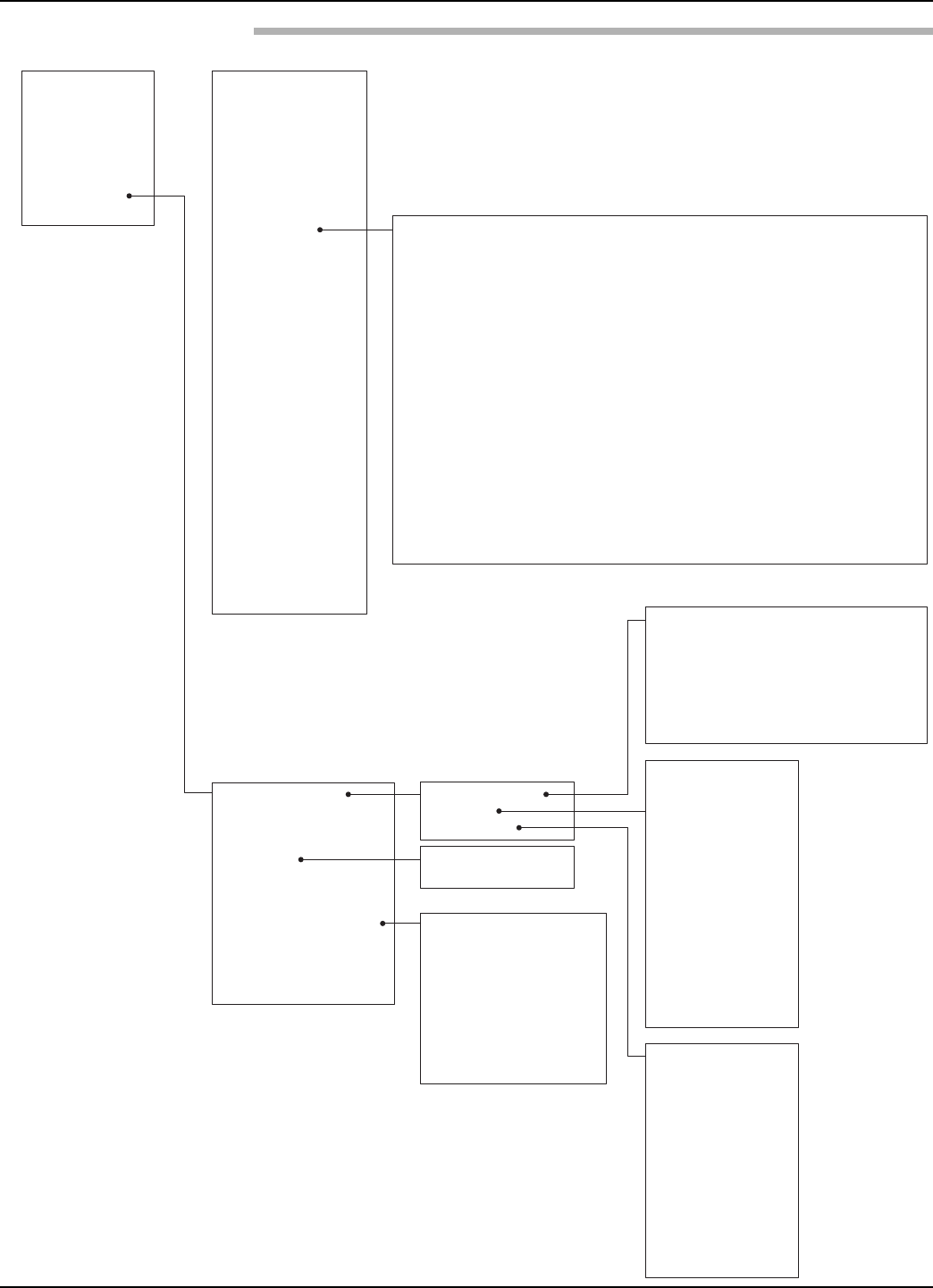
2.6.7 HART Menu
1Device Setup
2PV
3 Level
4Volume
5 Distance
6Echo Strength
7PV % Output
8 PV Loop
9Diagnostics
10 Local Tag
1Basic
Configuration
2 Advanced
Configuration
3 Device
Description
1 Trim Loop Current
2 Local Tag
3 New User Password
4 Antenna Mount
5 Factory Parameters
1 Tag
2 Descriptor
3 Date
4 Message
5 Poll Address
6 Magnetrol S/N
7 Device ID
8 Final asmbly num
1Measurement Type
2 Level Units
3Volume Units
4Strapping Table
5 Sensor Offset
6Tank Top
7 Tank Height
8Blocking Distance
9Level Offset
10 Dielectric
11 Turbulence
12 Foam
13 Rate of Change
14 Echo Profile
15 PV is
16 4–20mA Setpoints
17 Variable Selection
18 Damping
19 System Fault
20 Echo Loss Fault
21 Echo Loss Delay
22 Safe Zone Fault
23 Safe Zone Height
24 Trim Level
25 Pipe ID
1Table Type‐Linear
2 Table Length
3Point 01 Level
4Point 01 Volume
5Point 20 Level
6 Point 20 Volume
1 SV is
2TV is
3 4V is
1 Enter Password
2 Reset Temperatures
3 Echo Profile
4 Target Algorithm
5 TVG Type
6 TVG Maximum
7 Peak Detect Ref
8 Peak Detect Thresh
9 Min Threshold
10 # Run Average
11 # Adaptive Average
12 Scatter High Limit
13 Rate High Limit
14 Scatter
15 Filter Level Rate
16 Level Velocity
17 Max Rate
18 Max ROC per Min
19 Max Distance Jump
20 Boundary Condition
State
21 Empty State Delay
22 FactPar1
23 FactPar 2
24 NSPValue
25 Factory Calibration
1 4mA Set Point
220ma Set Point
1 Echo List Mode
2 Echo 1 Location
3Echo 1 Strength
18 Echo 9 Location
19 Echo 9 Strength
20 Enter Distance
21 SavedEchoRejPrfl
1 Enter Password
2 Window
3 Target Distance
4 Conversion Factor
5 Scale Offset
6 System Gain
1 Echo Rejection
2Echo 1 Location
3 Echo 1 Strength
18 Echo 9 Location
19 Echo 9 Strength
20 Saved Distance @
1 Refresh Echo List
2 Location Mode
3 Signal Units
2 Echo 1 Location
3 Echo 1 Strength
18 Echo 9 Location
19 Echo 9 Strength
28 58-610 Model R82 Radar Transmitter
2.6.7 HART Menu (cont.)
1Basic
Configuration
2Advanced
Configuration
3 Device
Description
4 Review
5 Date/Time/Initials
1Device Setup
2Level
3 Volume
4Distance
5 Echo Strength
6% Output
7Loop Current
8 Diagnostics
9Local Tag
1 View History
2 Reset History
1 Model
2 Manufacturer
3Magnetrol S/N
4 Firmware Version
5Tag
6 Descriptor
7Date
8Message
9 Final asmbly num
10 Poll Address
11 Local Tag
12 Device ID
13 Date/Time/Initials
14 Universal rev
15 Fld dev rev
16 Sofware rev
17 Num req preams
18 Measurement Type
19 Level Units
20 Volume Units
21 Sensor Offset
22 Tank Top
23 Tank Height
24 Blocking Distance
25 Level Offset
26 Dielectric
27 Turbulence
28 Foam
29 Rate of Change
30 PV is
31 SV is
32 TV is
33 4V is
34 4 mA Set Point
35 20 mA Set Point
36 Damping
37 System Fault
38 Echo Loss Fault
39 Echo Loss Delay
40 Safety Zone Fault
41 Safety Zone Height
42 Trim Level
43 Pipe ID
44 4mA Trim Value
45 20mA Trim Value
46 Target Algorithm
47 TVG Type
48 TVG Maximum
49 Peak Detect Ref
50 Peak Detect Thresh
51 Min Threshold
52 # Run Average
53 # Adapt Average
54 Scatter High Limit
55 Rate High Limit
56 Max Rate
57 Max Distance Jump
58 Empty State Delay
59 Window
60 Target Distance
61 Conversion Factor
62 Scale Offset
63 System Gain
1 Present Status
2 History
3 Extended Diagnostics
4 Trend Chart
5 Echo Graph
1 Device Status
2 Faults
3 Warnings
1 DfltParmFact
2 DfltParm Sys
3 DfltParm Adv
4 DfltParm I/O
5 DfltParmHART
6 DfltStrapTbl
7 Fault 4
8 CnfgConflict
9 RFBrdFailure
10 Loop Failure
11 Fault 3
12 SafeZoneAlrm
13 Echo Lost
14 Fault 2
15 HiVolumeAlrm
16 Fault 1
1 Initializing
2 Warning 4
3 LowVDC@20mA
4 Warning 3
5 NoEchoRej
6 EchoRejCrpt
7 EchoRejInvl
8 EchoRejDisable
9 Warning 2
10 ElecTemp Hi
11 Elec Temp Low
12 Rate Of Change
13 Warning 1
14 System Code
1 Primary variable out of limits
2 Non‐primary variable out of limits
3 Primary variable analog output saturated
4 Primary variable analog output fixed
5 More status available
6 Cold start
7 Configuration changed
8 Field device malfunction
1 Loop Test
2 Manual Low VDC Check
3 Low VDC Check State
4 Low VDC Check Voltage
5 VDC Check Midpoint
6 Electronics Temperature
7 Max Temperature
8 Min Temperature
9 Reset Safe Zone Alarm
10 Firmware Version
29
58-610 Model R82 Radar Transmitter
3.0 Reference Information
This section presents an overview of the operation of the
Model R82 Radar Level Transmitter, information on trou-
bleshooting, common problems, listings of agency
approvals, lists of replacement and recommended spare
parts, and detailed physical, functional and performance
specifications.
3.1 Description
The Model R82 is a two-wire, 24 VDC level transmitter
based on the concept of pulse burst radar operating at
26GHz. The electronics are mounted in a metal or plastic
housing with an innovative, internal launcher orientation
mechanism.
3.2 Theory of Operation
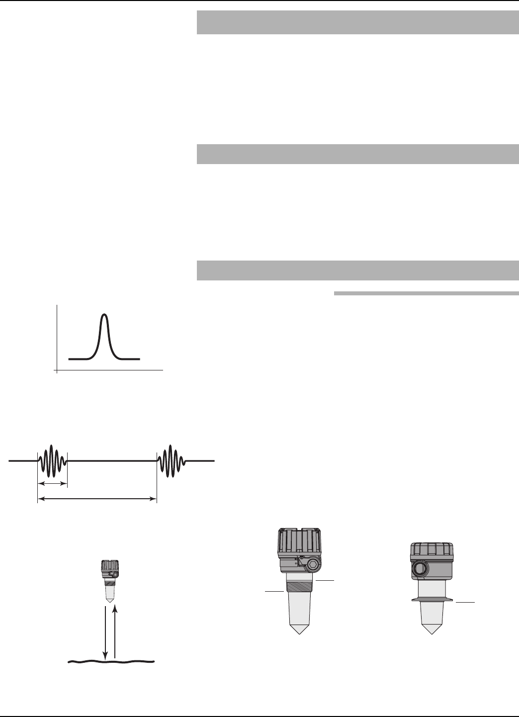
3.2.1 Pulse Burst Radar
The Model R82 is a top-mounted, downward-looking pulse
burst radar operating at 26 GHz. Unlike true pulse devices
that transmit a single, sharp (fast rise-time) waveform of
wide-band energy, the R82 emits short bursts of 5.8 or
26GHz energy and measures the transit time of the signal
reflected off the liquid surface. Distance is calculated utiliz-
ing the equation Distance = C ×Transit time/2, then devel-
oping the Level value by factoring in Tank Height and
Sensor Offset information. The exact reference point for
distance and level calculations is the Sensor Reference
Point—bottom of an NPT thread, top of a BSP thread or
face of a flange.
Distance = c ´(time ¸2)
1 ns
500 ns
NPT
Process
Connection
BSP
Process
Connection
Sanitary
Sensor Reference Point
Pulse
Pulse Burst
30 58-610 Model R82 Radar Transmitter
The exact level measurement is extracted from false echo
reflections and other background noise via the use of sophis-
ticated signal processing. The new R82 circuitry is extreme-
ly energy efficient so no duty cycling is necessary to accom-
plish effective measurement. For this reason, the R82 can
track high rates of change that were heretofore impossible
with existing loop-powered radar transmitters.
3.2.2 Equivalent Time Sampling
ETS, or Equivalent Time Sampling, is used to measure the
high speed, low power EM (electromagnetic) energy. ETS is
a critical key in the application of Radar to vessel level
measurement technology. The high speed electromagnetic
energy (1000 ft/µs) is difficult to measure over short dis-
tances and at the resolution required in the process industry.
ETS captures the EM signals in real time (nanoseconds) and
reconstructs them in equivalent time (milliseconds), which
is much easier to measure with today’s technology.
ETS is accomplished by scanning the tank to collect thou-
sands of samples. The round-trip event on a 40-foot (12.3m)
tank takes only 82 nanoseconds in real time. After it is
reconstructed in equivalent time it measures 123 milliseconds.
Tank
Height
Sensor Offset + Tank Height =
Distance from process
connection to tank bottom
20 mA
4 mA
Sensor Reference Point
Sensor Offset (+)
Blocking
Distance
Distance
Safe Zone
Media
Level
Level Offset
Lowest
Measurable
Value
31
58-610 Model R82 Radar Transmitter
3.3 Troubleshooting
The Model R82 transmitter is designed and engineered for
trouble-free operation over a wide range of operating
conditions. Common transmitter problems are discussed
in terms of their symptoms and recommended corrective
actions.
WARNING! Explosion hazard. Do not remove covers unless power
has been switched off or the area is known to be non-
hazardous.
Use of the included PACTware™PC program is highly
recommended and invaluable for troubleshooting and
advanced calibration. A HART RS232 or USB modem
(purchased separately) is required. See Magnetrol
PACTware™bulletin 59-101.
Symptom Problem Solution
Level reading drops out at a
repeatable position in the
vessel
Multipath is cancelling good
level signal
Orient launcher to reduce multipath; turn launcher 10–20 degrees (1–2 index
marks) at a time until multipath at this point disappears. Refer to Section 2.4.2.3
Level reading locked onto a
value that is not correct
Level
Measurement engine finding
a reflection it believes is
level signal
1. Is high dielectric (ε>10) foam present
2. Run False Target Rejection routine with Level below this point (or with Empty
tank) to eliminate false echoes
LEVEL, % Output and LOOP
values are all inaccurate
Basic configuration data
questionable
1. Check validity of all configuration data
2. Check DISTANCE value of device against manually measured distance
LEVEL readings are repeat-
able but consistently high (or
low) from actual by a fixed
amount
Configuration data does not
accurately match tank
dimensions
1. Ensure proper values for Tank Height and Sensor Offset
2. Check vessel for present liquid level. Trim Level can be used to ensure
exact measurement
3. Reconfigure LOOP values if necessary
LEVEL reading on Display is
correct but LOOP is stuck at
4 mA
HART Poll Address set a
value of 1-15
Set HART Poll Address to 0
LEVEL reading on Display
stuck at value related to
Blocking Distance
Device believes antenna is
flooded (level very near or
on antenna)
Check actual level. If antenna is not flooded, power down, then power up
transmitter with the level well below the antenna.
3.3.1 Troubleshooting System Problems
32 58-610 Model R82 Radar Transmitter
3.3.2 Error Messages
The Model R82 Radar transmitter utilizes a 3-section
hierarchy for reporting diagnostic conditions: FAULTS,
WARNINGS, and INFORMATION. This information
will be shown in the Home screen when the message is
active. A chronological listing of messages can be viewed
in the HISTORY screen.
FAULT: The highest level in the hierarchy of diagnostics
annunciating a defect or failure in circuitry or software that
precludes reliable measurement. The current (mA) value
unit defaults to 3.6, 22, or HOLD and the Home screen
will freeze showing the highest priority Fault. Other Faults
can also be viewed using the UP/DOWN arrows. A chrono-
logical listing of messages can be viewed in the HISTORY
screen.
WARNING (MESSAGE): The second level in the hierar-
chy of Diagnostics annunciating conditions that are not
fatal but may affect measurement. The highest priority
Warning will be placed on the main (rotating) screen when
a Warning is detected but will not affect output current.
Other Warnings can also be viewed using the UP/DOWN
arrows. A chronological listing of messages can be viewed
in the HISTORY screen.
INFORMATION (MESSAGE): The lowest level in the
hierarchy of diagnostic conditions providing operational
factors that are not critical to measurement. A chronological
listing of messages can be viewed in the HISTORY screen
mA Loop Display Message History Screen ➀
Fault 3.6/22/HOLD Yes Yes
Warning No Effect Yes Yes
Information No Effect No Yes
EFFECTS OF EACH DIAGNOSTIC MESSAGE
➀Also listed in History screen are changes of "state". For example, "BC Level" which
means Boundary Condition Level. This is an expression of the transmitter’s internal logic.

33
58-610 Model R82 Radar Transmitter
Symptom Condition(s) Solution(s)
Faults
DfltParmFact
Non-volatile memory corrupted
• Modify one parameter in the section then return
setting to original value (e.g., change HART
POLL ADR from 0 to 1 then back to 0.
• Consult Factory if this does not resolve the
problem
DfltParm Sys
DfltParm Adv
DfltParm I/O
DfltParmHART
DfltStrapTbl
RFBrdFailure Ramp interval out of tolerance Consult Factory
Loop Failure
The actual current generated in the 4-20 mA loop
differs significantly (> 1 mA) from the intended
loop current.
Consult Factory
SafeZoneAlrm
Level has risen to within SZ Height of Blocking
Distance point.
SZ Alarm notification choices:
i) 22 mA: loop driven to 22 mA while detected
level remains within SZ Height of Blocking
Distance point
ii) 3.6 mA: loop driven to 3.6 mA while detected
level remains within SZ Height of Deadband
iii) Latch 22 mA: loop held at 22 mA until
manually reset
iv) Latch 3.6 mA: loop held at 3.6 mA until
manually reset
None: safety zone not enabled. (default Safety
Zone Alarm state)
• Normal operation
• Change parameters to modify transmitter
actions
• Keep liquid from entering this area
Echo Lost
No valid echo from the liquid surface has been
received for a period exceeding the Echo Loss
Delay.
• Increase Turbulence setting
• Decrease Dielectric setting
• Increase Foam setting
• Increase ROC setting
• Increase LOE Delay
HiVolumeAlrm The measured level exceeds the strapping table
SPAN by more than 5%.
• Increase the maximum Level/Volume capability
of the table
• Prevent liquid from reaching this level
Warnings
Initializing Instrument is warming up Normal operation
LowVDC@20mA Test_Power reading is so low that brownout may
occur at high current values.
• Reduce resistance in loop
• Increase power supply voltage
No EchoRej No Echo Rejection Profile has been saved • Run new Echo Rejection Profile
• Turn OFF Echo Rejection warning
EchoRej Crpt Non-volatile memory exception in Echo Rejection
Profile partition
• Re-run Echo Rejection Profile
• Consult Factory
EchoRej Invl
A stored Echo Rejection Profile has been invali-
dated; typically because a key configuration
parameter was changed.
Re-run Echo Rejection Profile
EchoRej Dsbl Echo Rejection has been disabled • Enable Echo Rejection
• Turn OFF Echo Rejection warning
EchoRej Insf Echo Rejection Curve ended within a partial Echo Re-run Echo Rejection Profile at a higher or lower
Level to avoid capturing a partial echo
Elec Temp Hi1 Electronics temperature presently above 80°C Reduce exposure of transmitter to high tempera-
ture to avoid damage
Elec Temp Lo2 Electronics temperature presently below -40°C Reduce exposure of transmitter to low tempera-
ture to avoid damage
RateOfChange Rate of level change has exceeded user setting
for ROC. Increase Rate of Change setting
DIAGNOSTIC MESSAGES
34 58-610 Model R82 Radar Transmitter
Symptom Condition(s) Solution(s)
Informational
System Code Unexpected but non-fatal software condition has
occurred Consult Factory
BC Initial
BC Level
BC Empty
BC Full
BC EchoMiss
BC EchoLost
BC Restart
Boundary Condition State Normal operation
NoTargetFound Echo processing module detected no echoes
above threshold
• Ensure proper installation
• Ensure proper configuration-specifically
Dielectric, Turbulence, Foam
• Ensure proper application for radar
• Consult Factory
Dist Jump Echo processing module detected actual or
impending discontinuity in distance measurement
Transmitter detecting echoes other than valid
liquid level and may jump to erroneous level
Target?? Target distance uncertain due to abnormal shape
of location Consult Factory
DIAGNOSTIC MESSAGES
35
58-610 Model R82 Radar Transmitter
3.4 Agency Approvals
FM R82-52XA-0XX Intrinsically Safe Class I, Div. 1; Groups A, B, C, & D
NEMA 4X, IP 66 T4 @80°C ➀
Entity
R82-52XA-0XX Non-Incendive ➁Class I, Div. 2; Groups A, B, C, & D
NEMA 4X, IP 66 ➀
CSA R82-52XA-0XX Intrinsically Safe Class I, Div. 1; Groups A, B, C, & D
NEMA 4X, IP 66 T4 @80°C ➀
Entity
R82-52XA-0XX Non-Incendive ➁Class I, Div. 2; Groups A, B, C, & D
NEMA 4X, IP 66 T4 @80°C ➀
ATEX R82-5BXA-0XX Intrinsically Safe ➂➃ ATEX II 1G Ex ia T4 @70°C
Ambient Temp: -40° to +70° C ➀
(EN60079-0: 2007, EN60079-11: 2007
&EN60079-26: 2007 standards applied
AGENCY MODEL PROTECTION METHOD AREA CLASSIFICATION
These units have been tested to
EN 61326 and are in compliance
with the EMC Directive 2004/108/EC.
COMMUNICATIONS APPROVALS ATEX Entity Parameters
Region Agency Frequency
US FCC
26 GhzCanada IC
Europe RTTE
Vi 28.4 VDC
li 120 mA
Pi 0.82 w
Ci 5.5 nF
Li 370 µH
Model R82
SIL 1 as 1oo1
Instrument Type B
SFF 73.7%
PFDavg 9.72E-04
FITS Annual
Fail Dangerous Undetected 222 1.94E-03
Fail Dangerous Detected 308 2.70E-03
Safe 314 2.75E-03
➀NEMA rating: -20 to +80C (Tefzel®antenna only)
➁For Division 2 the measured media inside the vessel must be non-flam-
mable only and the apparatus must be only connected to an inherently
limited power source (Class 2 power supply) as defined in the NEC
table 11
Special conditions for safe use (ATEX Ex i)
➂Materials marked as category 1 equipment and mounted in hazardous
areas requiring this category shall be installed in such way that, even in
the event of rare incidents, the aluminum enclosure cannot be an ignition
source due to impact or friction.
➃The transmitter shall be installed so that electrostatic discharges on
plastic parts are prevented.
SIL

36 58-610 Model R82 Radar Transmitter
3.4.1 Agency (FM/CSA) Drawing and Entity Parameters
<< Drawing pending approval >>
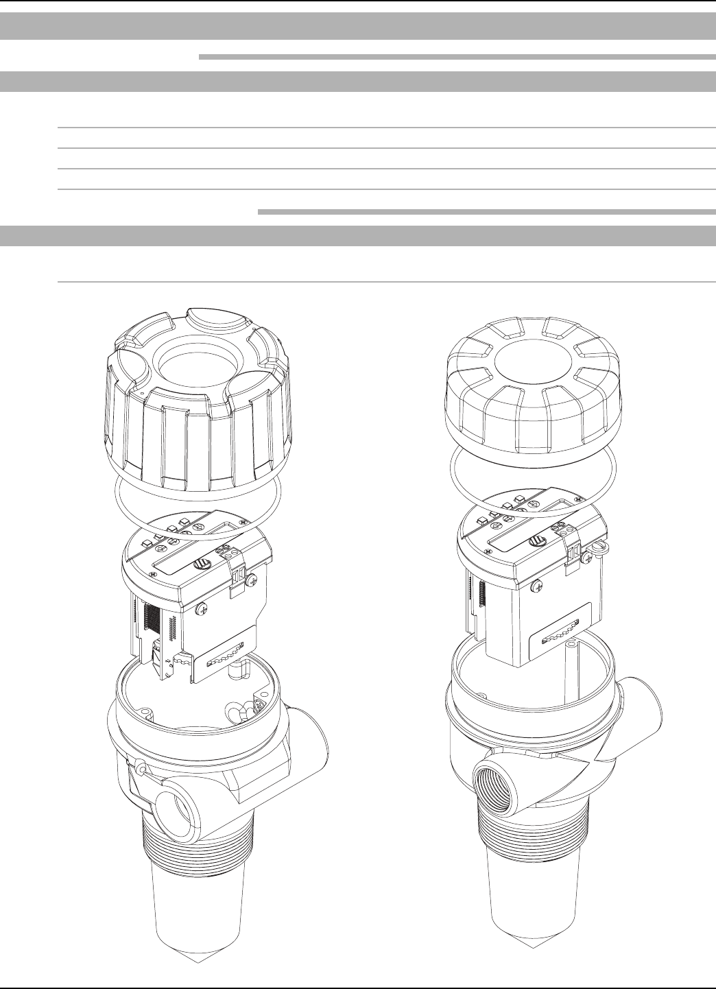
37
58-610 Model R82 Radar Transmitter
3.5 Parts
3.5.1 Replacement Parts
Item Description Part Number
➀Electronic Module – 26 GHz Aluminum Housing 89-9124-001
Lexan®Housing 89-9124-002
➁O-ring: Viton 012-2201-237
➂Housing Cover, Aluminum GP/IS 036-4410-010
➃Housing Cover, Lexan GP/IS 003-1226-003
3.5.2 Recommended Spare Parts
Description Part Number
Electronic Module – 26 GHz Aluminum Housing 89-9124-001
Lexan Housing 89-9124-002
➂
➁
➀
➃
➁
➀
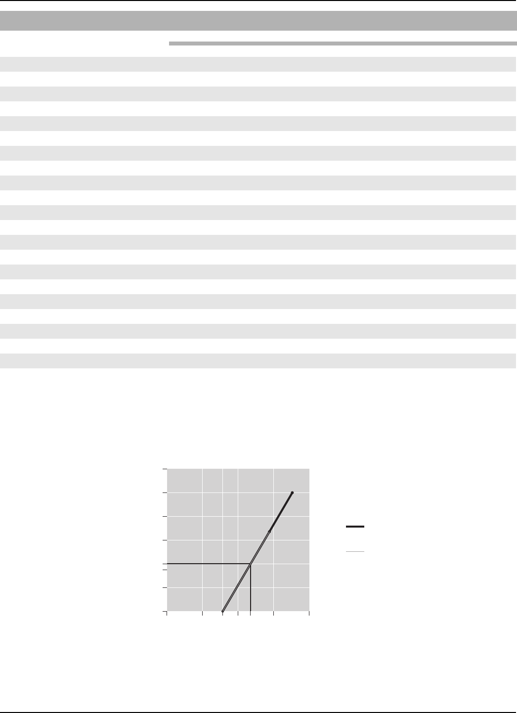
38 58-610 Model R82 Radar Transmitter
Ω
VDC
1200
1000
28.6 V
630 Ω
@ 20 mA
36 V
1000 Ω
800
600
400
200
0
0 10 20
16
350
30 40
General Purpose &
Explosion Proof
Intrinsically Safe
(350 @ 22 mA)
24
System Design
Measurement Principle Pulse burst radar @ 26 GHz ➀
Input
Measured Variable Level, determined by the time-of-flight of a radar pulse from
transmitter to product surface and back
Span 15" to 40 feet (380 mm to 12.2 m) measured from threads
Output
Type Analog 4 to 20 mA with optional HART digital signal
Range Analog 3.8 to 20.5 mA useable (Namur NE43)
Digital 0 to 999" (0 to 9999 cm)
Resolution Analog 0.01 mA
Digital 0.1"
Loop Resistance GP/IS/XP - 400 Ω@ 24 VDC/20 mA, 350 Ω@ 24 VDC/22 mA
Diagnostic Alarm Adjustable 3.6 mA, 22 mA, HOLD
Damping Adjustable 0-45
Output at Antenna < .01 mW (avg), < 2 mW (max)
User Interface
Keypad 4-button menu-driven data entry and system security
Indication 2-line ×16-character display
Digital Communication ➀HART Version 5 compatible
Power (Measured at instrument terminals)
General Purpose/Intrinsically Safe 16 to 36 VDC
3.6 Specifications
3.6.1 Functional – Transmitter
➀RTTE: European approval, FCC & IC: North American approval

39
58-610 Model R82 Radar Transmitter
Housing
Material: Lexan®base and cover
Cast aluminum A356T6 (<0.2% copper)
Cable Entry: ¾" NPT, M20
Ingress Protection: Lexan Housing: NEMA 6P (IP67/68)
Aluminum Housing: NEMA 4X/6P (IP67/68)
Net/Gross Weight: Short Lexan 23 oz.
Long Lexan 32 oz.
Short Aluminum 49 oz.
Long Aluminum 58 oz.
Overall Dimensions: Lexan see drawings on page 41
Aluminum see drawings on page 41
Antenna
Encapsulated Horn Polypropylene, Tefzel®(optional)
-40 to +200F @atmos (-40 to 93C)
Vacuum to 200 psig @ 70F (-14.5 to 13.8 bar) Tefzel
Wetted Surfaces Polypropylene or Tefzel (optional)
Environment
Operating Temperature -40 to +175° F (-40 to +80° C)
LCD -5 to +160° F (-20 to +70° C)
Storage Temperature -50 to +175° F (-46 to +80° C)
Humidity 0-99%, non-condensing
Electromagnetic Meets CE Requirements: EN 50081-2, EN 50082-2
Surge Protection Meets CE Requirements: EN 61326 (1000 volts)
Shock Class ANSI/ISA-S71.03 Class SA1
Vibration Class ANSI/ISA-S71.03 Class VC2
3.6.1 Functional – Transmitter (cont.)
Reference Conditions Reflection from ideal reflector at +70° F (+20° C)
Linearity ±0.2 inch (5 mm) or 0.05% of tank height (whichever is greater)
Measured Error ±0.2 inch (5 mm) or 0.05% of tank height (whichever is greater)
Resolution 0.1 inch (2.5 mm)
Repeatability < 0.1 inch (2.5 mm) or 0.025% of tank height
Response Time < 1 second
Warm-up Time 30 seconds
Ambient Temp. Effect 0.05% per 10° C
Process Dielectric Effect < 0.3 inch within selected range
Maximum Rate of Change 180 inches (450 cm)/minute
Minimum Dielectric: 1.7
3.6.2 Performance

40 58-610 Model R82 Radar Transmitter
3.6.3 Functional – Encapsulated Horn Antenna
3.6.4 Antenna Pressure / Temperature Ratings
Both the Polypropylene and Tefzel antennas are rated from
full vacuum to 200psig (-14.5 to 13.8 bar) across the entire
temperature range of -40 to +200F (-40 to +93C).
Antenna Polypropylene Tefzel®
Process Connection 2" NPT/BSP sanitary flanges
Maximum Process
Temperature
-40° to +200° F @ atmos
(-40° to +93° C @ atmos)
Maximum Process
Pressure
Vacuum to 200 psig @ +70° F
(-14.5 to 13.8 bar @ +20° C)
Minimum Dielectric
(application dependent) 1.7
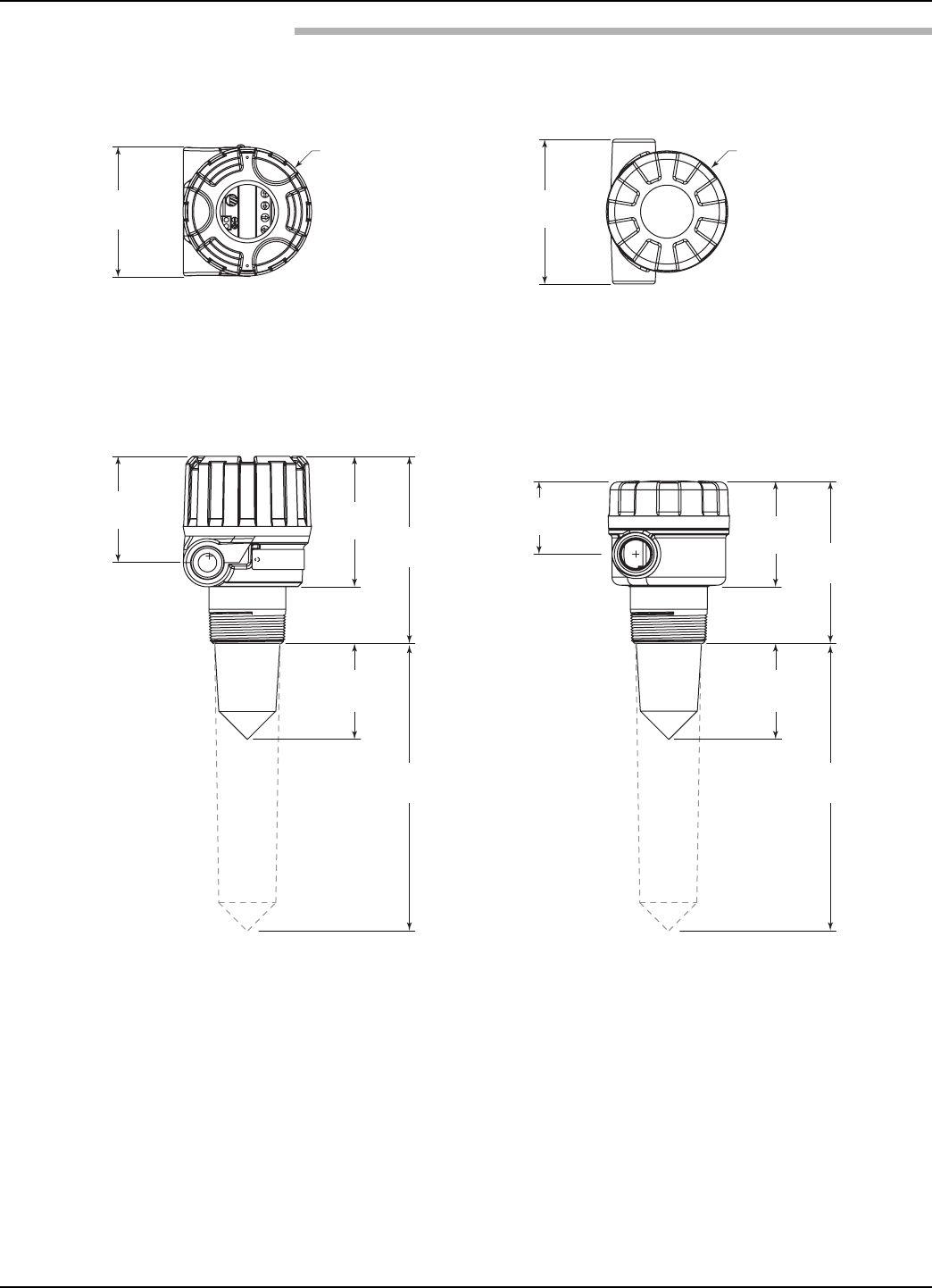
41
58-610 Model R82 Radar Transmitter
Ø4.00
(102)
4.50
(114)
4.00
(102)
3.31
(84) 4.06
(103)
2.98
(76)
5.82
(148)
8.98
(228)
2.27
(58) 3.25
(83)
2.98
(76)
5.04
(128)
8.98
(228)
Ø3.78
(96)
3.6.5 Physical – Inches (mm)
Aluminum Housing
Top View
Lexan®Housing
Top View
Aluminum Housing
Side View
Lexan®Housing
Side View
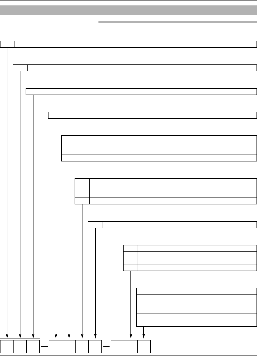
42 58-610 Model R82 Radar Transmitter
3.7 Model Numbers
3.7.1 Model R82 Radar Transmitter
R82 5A0
R RADAR Level Transmitter
BASIC MODEL NUMBER
8 26 GHz
OPERATING FREQUENCY
2 Economical
TRANSMITTER MODEL
5 24 VDC, Two-wire; 4-20 mA with HART®
POWER/SIGNAL
1 Integral, General Purpose/Non-incendive (cFMus)
2 Integral, Intrinsically Safe (cFMus)
A Integral, General Purpose (ATEX)
B Integral, Intrinsically Safe (ATEX II 1/2G EEx ia IIC T6)
AGENCY CLASSIFICATION
A Digital display and keypad
ACCESSORIES
0 Cast Aluminum, Single Compartment; 3⁄4" NPT
1 Cast Aluminum, Single Compartment; M20
6 Lexan®Plastic, Single Compartment, 3⁄4" NPT
7 Lexan Plastic, Single Compartment, M20
HOUSING/CONDUIT CONNECTION
1 Polypropylene, 2" (50 mm) extension
2 Polypropylene, 8" (200 mm) extension
3 Tefzel®, 2" (50 mm) extension
4 Tefzel, 8" (200 mm) extension
ANTENNA TYPE
1 2" NPT
2 2" BSP
A2
1⁄2" Tri-Clover®
B 3" Tri-Clover
C 65 mm Tuchenhagen
D 80 mm Tuchenhagen
PROCESS CONNECTION

43
58-610 Model R82 Radar Transmitter
Accuracy The closeness of agreement between the result of
measurement and the true value of the measure (inaccuracy
equals the maximum positive and negative % deviation over the
total span).
ANSI American National Standards Institute.
Antenna A mechanical component that serves as an impedance
match between the transmission of a signal in a cable (or wave-
guide) and air.
AntnaMnt Antenna Mount The type of process mounting
(NPT, BSP or Flange) utilized in the installation. This aids in
establishing an exact Sensor Reference Point for Radar propaga-
tion and measurement.
AntnaTyp Antenna Type A particular antenna configuration or
design. Each antenna design has a set of unique performance
characteristics.
ATEX ATmosphere EXplosive European regulations governing the
use in hazardous areas.
BlockDist Blocking Distance The area near the antenna where
reflections cannot be measured effectively due to antenna ringing
and noise.
CE Conformité Européene Standards and performance criteria for
the new European Union.
CENELEC Comité Européen de Normalisation Electrotechnique
European organization that sets standards for electrical equipment.
CSA Canadian Standards Association Canadian, third party
agency that qualifies the safety of electrical equipment.
Damping Factor applied to smooth output variations due to
turbulence.
Default Screen The main position of the menu structure that
displays the primary measurement values of LEVEL, Quality,
% OUTPUT, and LOOP. The transmitter returns to this
position after 5 minutes of inactivity (except Screens 2-6).
Diagnostics Three levels of error messages; Fault, Warning and
Information.
Dielectric Constant (ε) The electrical permittivity of a material.
The units are farad/meter. Typical values: Hydrocarbons 1.9–3,
Glycol 32, Water-based media 80. See Technical Handbook
41-600 for complete listing.
Dielectric Rod antenna A non-metallic (TFE and polypropylene
typical) transition between the microwave waveguide and air.
Distance The present reading measured from the transmitter’s
Sensor Reference Point to the material in a vessel; compliment
of Level.
DVM/DMM Digital Volt Meter/Digital Multimeter.
Electromagnetic Energy The radiation that travels through
space as electric and magnetic fields varying with position and
time. Examples in increasing frequency: radio waves, microwave,
infrared light, visible light, ultraviolet light, x-rays, gamma
waves, and cosmic waves.
EM See Electromagnetic Energy.
EMI Electromagnetic Interference Electrical noise caused by elec-
tromagnetic fields that may affect electrical circuits, particularly
low-power electronic devices.
EN European Normal Committee guidelines in EC countries
that take precedence over local, country guidelines.
ENV Preliminary EN guidelines, or pre-standards.
Ergonomic A mechanism that considers human capability in its
design or function.
ETS Equivalent Time Sampling Process that captures high speed
electromagnetic events in real time (nanoseconds) and recon-
structs them into an equivalent time (milliseconds).
Explosion Proof Enclosure An enclosure designed to withstand
an explosion of gas or vapor within it and prevent the explosion
from spreading outside the enclosure.
Factory Sealed A third-party-approved Explosion Proof seal
installed in the unit during manufacturing. This alleviates the
end user from installing an external XP seal adjacent (within
18") to the device.
Fault The highest level in the hierarchy of diagnostics annunci-
ating a defect or failure in circuitry or software that preclude reli-
able measurement. The current (mA) value unit defaults to 3.6,
22, or Hold and a message is displayed on the rotating screen.
Further information can be obtained by viewing the Status or
Diagnostic (Factory Menu) screens.
Feedthrough A small, connecting cavity between the main hous-
ing compartments, carrying the cable that supplies the operating
energy to the measurement circuitry and returns the output
value proportional to level. This cavity is potted to maintain the
environmental isolation between the two compartments.
Fiducial A reference signal (baseline) to which all measurements
are referenced.
FM Factory Mutual American, third party agency that qualifies
the safety of electrical equipment.
Foam The entraining of air in a liquid. The effect of foam on
radar measurement is based on four factors; 1.) dielectric of the
liquid from which the foam has developed, 2.) density of the
foam (bubble size), 3.) amount of foam above the liquid and, to
a lesser extent, 4.) wall thickness of the bubbles.
Glossary

44 58-610 Model R82 Radar Transmitter
Four Wire An electronic instrument design that uses one set of
wires to supply power (120/240 VAC, 24 VDC) and another set
to carry the process measurement signal (4–20 mA). Also called
Line Powered.
FSK Frequency Shift Keying See HART.
Gain Amplification adjustment to attain optimum performance
in various product dielectric ranges. (Factory setting).
Ground An electrical connection to the Earth’s potential that is
used as a reference for the system and electrical safety.
Grounded A state where no electrical potential exists between
the ground (green) connection on the transmitter and the Earth
or system ground.
Guided Wave Radar See TDR.
HART Highway Addressable Remote Transducer Protocol that
uses the Bell 202 frequency shift keying (FSK) method to super-
impose low level frequencies (1200/2000 Hz) on top of the stan-
dard 4–20 mA loop to provide digital communication.
HART ID See Poll Address.
Hazardous Area An area where flammable gases or vapors are or
may be present in the air in quantities sufficient to produce
explosive or ignitable mixtures.
Horn Antenna A metallic, cone transition between the
microwave waveguide and air.
IEC International Electrotechnical Commission Organization that
sets international standards for electrical devices.
Increased Safety Designs and procedures that minimize sparks,
arcs, and excessive temperatures in hazardous areas. Defined by
the IEC as Zone 1 environments (Ex e).
Information (message) The lowest level in the hierarchy of diag-
nostic conditions providing operational factors that are not criti-
cal to measurement. Further information can be obtained by
viewing the Status or Diagnostic (Factory Menu) screens.
Intrinsically Safe Ground A very low resistance connecting to a
ground, in accordance with the National Electrical Code (NEC,
ANSI/NFPA 70 for FMRC), the Canadian Electrical Code
(CEC for CSA), or the local inspector.
Intrinsic Safety A design or installation approach that limits the
amount of energy that enters a hazardous area to eliminate the
potential of creating an ignition source.
Level The present reading of the height of material in a vessel;
compliment of Distance.
LevlOfst Level Offset The distance above the tank bottom where
radar level measurement is impossible due to heating coils, baf-
fles, angled or curved tank bottoms, etc. The mA output will
never read lower than the Level Offset value.
Linearity The worst case error calculated as a deviation from a
perfect straight line drawn between two calibration points.
Line Powered See Four Wire.
LOE Loss of Echo Condition where a level measurement is
impossible due to the absence of valid reflections from the liquid
surface.
LOE Delay Loss of Echo Delay The amount of time the trans-
mitter spends looking for a valid Level signal before going into
Loss of Echo Fault The last valid Level reading is held during
this search.
LOE Fault Loss of Echo Fault The mA value to which the output
is driven after the Loss of Echo Delay times out; choices are
3.6mA, 22mA and HOLD.
Loop The present reading of the 4–20 mA current output.
Loop Powered See Two Wire.
Loop Tst Loop Test Built-in system capability to test/calibrate a
loop (or separate loop device) by driving the transmitter output
to a particular value.
Low Voltage Directive A European Community requirement for
electrical safety and related issues of devices using 50-1000 VDC
or 75–1500 VAC.
Measured Value The typical level measurement values used to
track the level of a process: Level, % Output, and Loop.
Media The liquid material being measured by the level trans-
mitter.
Multidrop The ability to install, wire, or communicate with
multiple devices over one cable. Each device is given a unique
address and ID.
Non-hazardous Area An area where no volatile mixtures of
vapors/gas and oxygen will be found at any time. Also called
General Purpose Area.
Non-Incendive A circuit in which any arc or thermal effect pro-
duced, under intended operating conditions of the equipment or
due to opening, shorting, or grounding of field wiring, is inca-
pable, under specific test conditions, of igniting the flammable
gas, vapor, or dust-air mixture.
Password A numerical value between 0 and 255 that protects
stored configuration data from unauthorized manipulation.
Percent (%) Output The present reading as a fraction of the
16 mA scale (4–20 mA).
Poll Address (HART ID) A number between 1 and 15 which
sets an address or location of a device in a multi-drop loop. Poll
address for single device configuration is 0.
Qual Quality A relative value (0–99) that shows the strength
and usefulness for a given reflected signal.
QuickStart The essential information needed for the R82 radar
transmitter and antenna to be installed, wired, and calibrated.
Radar (Radio Detection And Ranging) Uses EM energy and
high speed timing circuits to determine distance. Original Radar
devices used energy in the radio frequency range (MHz), many
current devices use much higher frequencies (GHz).

45
58-610 Model R82 Radar Transmitter
Range The distance over which the transmitter scans for valid
return signals.
RateChng Rate of Change The maximum velocity of vertical
movement of a liquid’s surface.
Relative Dielectric (εr) A unitless number that indicates the
relative permittivity of a material.
Repeatability The maximum error between two or more output
readings of the same process condition.
RFI Radio Frequency Interference Electrical noise that can have
an adverse affect on electrical circuits, particularly low-power
devices.
Safety Zone A user-defined area just below the Blocking
Distance where level measurement still has a high degree of relia-
bility. Radar can develop ambiguous readings when the level
reaches the region of the antenna. An alarm can be annunciated
in this area for critical applications where reliable measurement is
a necessity for safety reasons.
Safety Zone Height The height of the region below the
Blocking Distance where an alarm will be annunciated upon
detection of liquid.
Safety Zone Fault An optional condition added, when necessary,
to ensure safe, reliable high-level readings in critical applications.
Choices are 3.6 mA, 22 mA, Latch 3.6 or Latch 22. If Latch 3.6
or Latch 22 are chosen, the loop current will remain in alarm
until it is cleared in SZ Latch menu screen.
Safety Zone Alarm Reset Use screen for clearing a Latched
Alarm set in Safety Zone Fault (above)
SnsrOfst Sensor Offset The distance (+ or -) between the
customer’s 100% reference point (tank top) and the Sensor
reference point (bottom of NPT thread, top of BSP thread
or face of flange).
Span The difference between the upper and lower limits of the
range.
Specific Gravity (SG) The ratio of the density of a material to
the density of water at the same conditions.
Sensitivity The amount of amplification applied to the Level
signal; a higher value aids in measuring low dielectric media; a
lower number assists in ignoring nearby objects.
Status The current state of the transmitter’s diagnostics; screen
updates every 10 seconds.
Targets Objects in the vessel that create reflections of the radar
signal (microwave energy).
Targ Rej Target Rejection The ability to ignore reflections from
objects in the vessel that are not the liquid level, i.e., false targets
(e.g. pipes, ladders, baffles).
Tank Ht Tank Height The tank measurement between the 0%
(tank bottom) and 100% (tank top).
Tank Top The 100% point in a vessel. Also considered for the
type of tank top; e.g. flat, dome, etc., which affects the develop-
ment of multiple echoes during high level conditions. Multiple
echoes can appear as an invalid Level signal.
TDR (Time Domain Reflectometry) Uses a waveguide to carry
EM energy to and from the surface of the media to measure dis-
tance; similar to conventional through-air Radar but much more
efficient. Also called Guided Wave Radar.
Trim 4/Trim 20 Built-in system capability to fine tune the
4 mA and 20 mA points so the transmitter output corresponds
exactly to user’s meter, DCS input, etc.
Trim Lvl Trim Level An offset parameter used to account for
various deviations in measurement. It is an offset value that can
force the transmitter to read the exact level reading.
Turbulnc Turbulence Agitation, or disturbance, of the liquid
level surface; greater the agitation, greater the scattering of the
radar signal (microwave energy).
Two Wire An electrical instrument design that uses one set of
wires to provide both the supply power and process measure-
ment signal. The process measurement is achieved by varying the
current of the loop. Also called Loop Powered.
Units The engineering units used to measure level in the
system. The choices are in (inches) and cm (centimeters).
Warning (message) The second level in the hierarchy of
Diagnostics annunciating conditions that are not fatal but may
affect measurement. A message will occur on the main (rotating)
screen when a Warning is detected but will not affect output cur-
rent. Further information can be obtained by viewing the Status
or Diagnostic screens.
46 58-610 Model R82 Radar Transmitter
Item Value Value
History
Device Status Run Time
Vessel Name
Vessel # Occurred Duration
Media Event 19
Media Dielectric 18
Tag # 17
Level 16
Measurement Type 15
Units 14
Sensor Offset 13
Tank Top 12
Tank Height 11
Blocking Distance 10
Level Offset 9
Dielectric 8
Turbulence 7
Foam 6
Rate of Change 5
Echo Profile 4
Echo List Mode 3
Echoes #1 Q____ - _______ 2
#2 Q____ - _______ Item (factory defaults) Value Value
#3 Q____ - _______ Run Time
#4 Q____ - _______ System Code
#5 Q____ - _______ Electronics Temp
Echo Rejection Max. Temperature
Loop Control Min. Temperature
4 mA point VDC Check Midpoint
20 mA point Antenna Mount
Damping Echo Profile
System Fault Target Algorithm
LOE Fault TVG Minimum
LOE Delay TVG Maximum
SZ Fault Peak Detect Reference
SZ Height Peak Detect Threshold
SZ Alarm Reset Min Thresold
Trim Level # Run Average
Pipe I.D. # Adapt Average
Trim 4 mA Scatter High Limit
Trim 20 mA Rate High Limit
Test 4-20 Loop Scatter Rate
HART Poll Address Lvl ROC per Min
New Password Max ROC per Min
Language Max Distance Jump
Serial Number Boundary State
Model R82 VerX.XXX Loop Fdbk AtoD
Empty State Delay
NSP Value
HART Device ID
Company
Date
R82 Radar Transmitter
Configuration Data Sheet
Copy blank page and store calibration data for future reference and troubleshooting.

47
58-610 Model R82 Radar Transmitter
Notes

BULLETIN: 58-610.0
EFFECTIVE: June 2009
5300 Belmont Road • Downers Grove, Illinois 60515-4499 • 630-969-4000 • Fax 630-969-9489 • www.magnetrol.com
145 Jardin Drive, Units 1 & 2 • Concord, Ontario Canada L4K 1X7 • 905-738-9600 • Fax 905-738-1306
Heikensstraat 6 • B 9240 Zele, Belgium • 052 45.11.11 • Fax 052 45.09.93
Regent Business Ctr., Jubilee Rd. • Burgess Hill, Sussex RH15 9TL U.K. • 01444-871313 • Fax 01444-871317
5300 Belmont Road • Downers Grove, Illinois 60515-4499 • 630-969-4028 • Fax 630-969-9489 • www.sticontrols.com
Copyright © 2009 Magnetrol International, Incorporated. All rights reserved. Printed in the USA.
Service Policy
Owners of Magnetrol/STI controls may request the return
of a control or any part of a control for complete rebuild-
ing or replacement. They will be rebuilt or replaced
promptly. Controls returned under our service policy
must be returned by Prepaid transportation.
Magnetrol/STI will repair or replace the control at no cost
to the purchaser (or owner) other than transportation if:
1. Returned within the warranty period; and
2. The factory inspection finds the cause of the claim to
be covered under the warranty.
If the trouble is the result of conditions beyond our con-
trol; or, is NOT covered by the warranty, there will be
charges for labor and the parts required to rebuild or
replace the equipment.
In some cases it may be expedient to ship replacement
parts; or, in extreme cases a complete new control, to
replace the original equipment before it is returned. If this
is desired, notify the factory of both the model and serial
numbers of the control to be replaced. In such cases, cred-
it for the materials returned will be determined on the
basis of the applicability of our warranty.
No claims for misapplication, labor, direct or consequen-
tial damage will be allowed.
Return Material Procedure
So that we may efficiently process any materials that are
returned, it is essential that a “Return Material
Authorization” (RMA) number be obtained from the fac-
tory, prior to the material's return. This is available
through Magnetrol/STI's local representative or by con-
tacting the factory. Please supply the following informa-
tion:
1. Company Name
2. Description of Material
3. Serial Number
4. Reason for Return
5. Application
Any unit that was used in a process must be properly
cleaned in accordance with OSHA standards, before it is
returned to the factory.
A Material Safety Data Sheet (MSDS) must accompany
material that was used in any media.
All shipments returned to the factory must be by prepaid
transportation.
All replacements will be shipped F.O.B. factory.
ASSURED QUALITY & SERVICE COST LESS
Viton is a registered trademarks of DuPont Performance Elastomers.
HART is a registered trademark of the HART Communication Foundation
PACTware is a trademark of PACTware Consortium
CSA logotype is a registered trademark of Canadian Standards Association
Tri-Clover is a registered trademark of Tri-Clover, Inc.
Tefzel is a registered trademark of Du Pont de Nemours and Company
Lexan is a registered trademark of General Electric