AMX ACBVIBE Sound Bar User Manual ACV 5100 QSG REV A

AMX LLC Sound Bar ACV 5100 QSG REV A

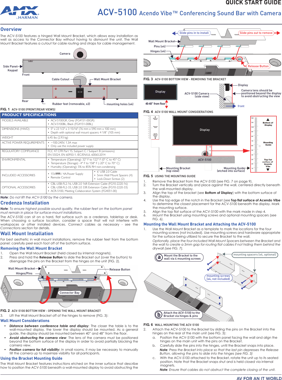
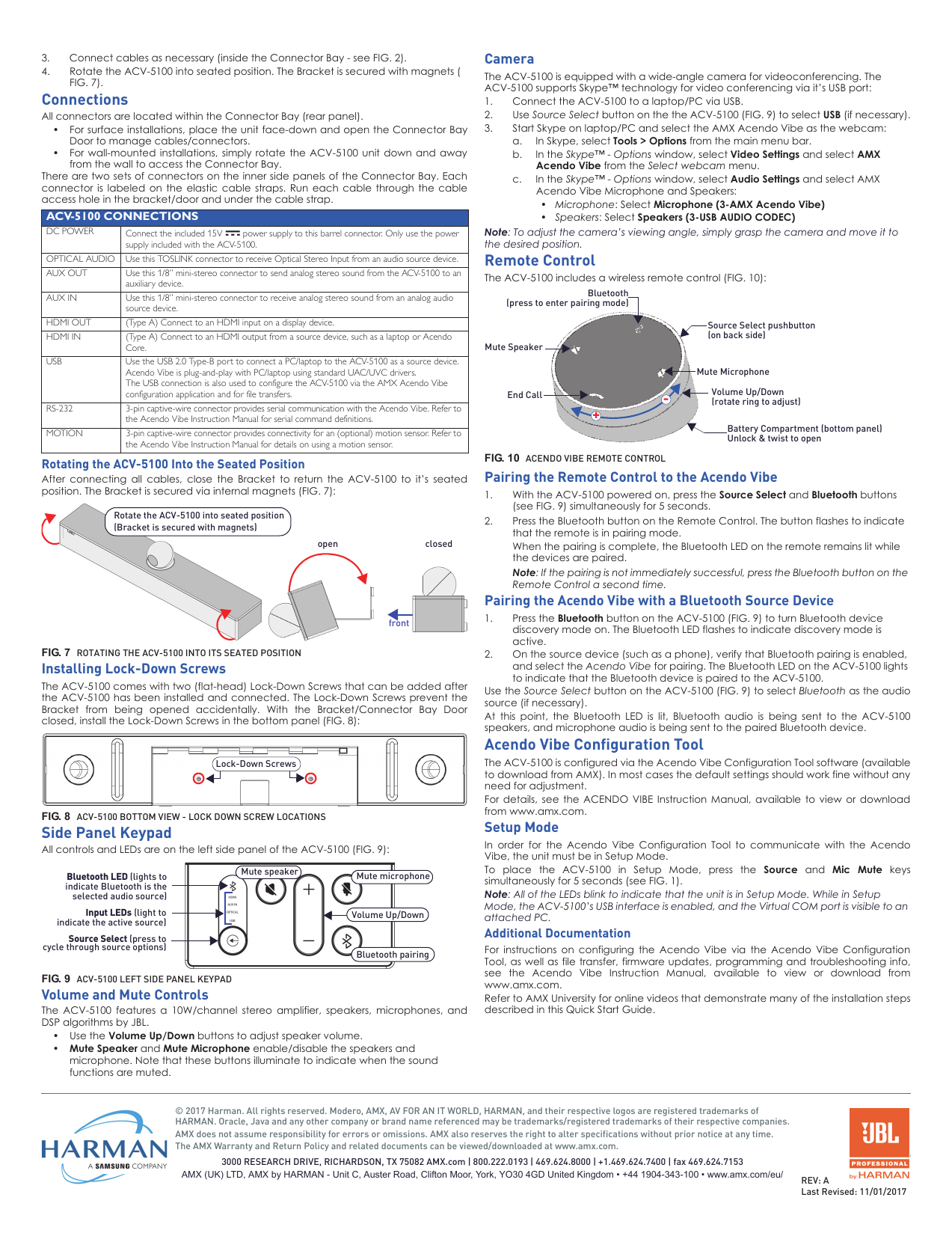
User Manual ACV-5100.QSG

QUICK START GUIDEACV-5100 Acendo Vibe™ Conferencing Sound Bar with CameraOverviewThe ACV-5100 features a hinged Wall Mount Bracket, which allows easy installation aswell  as  access  to the Connector  Bay  without  having  to  dismount  the  unit.  The WallMount Bracket features a cutout for cable routing and straps for cable management.   Note: Do not lift the ACV-5100 by the camera.Credenza InstallationNote: To ensure highest possible sound quality, the rubber feet on the bottom panel must remain in place for surface-mount installations.The ACV-5100  can  sit  on  a  hard,  flat  surface such as  a  credenza,  tabletop  or  desk.When choosing  a  surface  location,  consider  a  space that  will  not  interfere  withworkspaces  or  other installed devices. Connect  cables  as  necessary  -  see  theConnections section for details.Wall Mount InstallationFor best aesthetic in wall mount installations, remove the rubber feet from the bottompanel: carefully peel each foot off of the bottom surface.Removing the Wall Mount Bracket1. Open the Wall Mount Bracket (held closed by internal magnets).2. Press and hold the Release Button to slide the Bracket out (over the button) to disengage the pins on the Bracket from the hinges on the unit (FIG. 2).3. Lift the Wall Mount Bracket off of the hinges to remove (FIG. 3):  Wall Mount Considerations•Distance  between conference  table  and  display: The  closer  the  table  is  to  thewall-mounted  display.  the  lower  the  display  should  be  mounted.  As  a  generalguide, the display should be mounted between 40” and 48” from the floor.•Avoid obstructing the camera view: The  lens of  the camera  must be  positionedbeyond the bottom surface of the display in order to avoid partially blocking thecamera view.•Position camera for full visibility: In small rooms, it may be necessary to manuallytilt the camera up to maximize visibility for all participants. Using the Bracket Mounting GuideThe Wall Mount Bracket features instructions etched on the inner surface that describehow to position the ACV-5100 beneath a wall-mounted display to avoid obstructing the1. Remove the Bracket from the ACV-5100 (see FIG.7on page 9).2. Turn the Bracket vertically and place against the wall, centered directly beneath the wall-mounted display.3. Align the top of the bracket (see Bottom of Display) with the bottom surface of the display.4. Use the top edge of the notch in the Bracket (see Top flat surface of Acendo Vibe to determine the closest placement for the ACV-5100 beneath the display. Mark the mounting surface.5. Align the top flat surface of the ACV-5100 with the mark made in step 4.6. Mount the Bracket using mounting screws and optional mounting spacers (see FIG. 6).Mounting the Wall Mount Bracket and Attaching the ACV-51001. Use the Wall Mount Bracket as a template to mark the locations for the four mounting screws (not included). Use mounting screws and hardware appropriate for the surface being utilized to secure the Bracket to the wall.Optionally, place the four included Wall Mount Spacers between the Bracket and the wall to create a 5mm gap for routing flat cables if not hiding them behind the drywall (see FIG. 7).  2. Attach the ACV-5100 to the Bracket by sliding the pins on the Bracket into the hinges on the rear of the main unit (see FIG. 3):a.   Position the ACV-5100 with the bottom panel facing the wall and align the hinges on the main unit with the pins on the Bracket.b.   Carefully slide the pins into the hinges, until the Bracket snaps into place.Note: Press the Bracket into place so that the last pin depresses the Release Button, allowing the pins to slide into the hinges (see FIG. 3)c.   With the ACV-5100 attached to the Bracket, rotate the unit up to its seated position. Note that the Bracket snaps shut and is held closed via internal magnets.Note: Ensure that cables do not obstruct the complete closing of the unit. FIG. 1  ACV-5100 (FRONT/REAR VIEWS)PRODUCT SPECIFICATIONSMODELS AVAILABLE • ACV-5100GR, Grey (FG4151-00GR)• ACV-5100BL, Black (FG4151-00BL)DIMENSIONS (HWD) • 5" x 23 1/2" x 3 15/16" (76 mm x 590 mm x 100 mm)• Depth with optional wall mount spacers: 4 1/8” (105 mm))gk 39.2( sbl 54.6THGIEWACTIVE POWER REQUIREMENTS • ~100-240V, 1.3A max• Only use the included power supplyREGULATORY COMPLIANCE  FCC 47 CFR Part 15, Subpart C / Subpart B (emissions)EN 55024, EN 60950-1, IEC/EN/UL 60065:2014ENVIRONMENTAL • Temperature (Operating): 32° F to 122° F (0° C to   C)• Temperature (Storage): -4° F to 158° F (-20° C to 70° C)• Humidity (Operating): 5% to 85% RH non-condensingINCLUDED ACCESSORIES • 15V  / 4A.Power Supply• Remote Control• 6’ USB 2.0 Cable• 5mm Wall Mount Spacers (4)• Lock-Down Screws (2)OPTIONAL ACCESSORIES• CBL-USB-FL2-16, USB 2.0 16ft Extension Cable (FG10-2220-16)• CBL-USB-FL2-33, USB 2.0 33ft Extension Cable (FG10-2220-33)• ACR-5100, Meeting Collaboration System (FG4051-00)FIG. 2  ACV-5100 BOTTOM VIEW - OPENING THE WALL MOUNT BRACKETCameraFrontRearRubber feet (removable, x2) mounting holes (x4)Wall Mount BracketSide PanelKeypadCable CutoutWall Mount BracketHinges/PinsRelease ButtonConnector BayFIG. 3  ACV-5100 BOTTOM VIEW - REMOVING THE BRACKETFIG. 4  ACV-5100 WALL MOUNT CONSIDERATIONSFIG. 5  USING THE MOUNTING GUIDEFIG. 6  WALL MOUNTING THE ACV-5100Wall Mount BracketPins (x4)Hinges (x4)Slide pins in to install Slide pins out to removeRelease ButtonDisplay40-48” from floorCamera lens should bepositioned beyond the displayto avoid obstructing the viewDisplayACV-5100 CameraDisplayfront(side view)Mounting Bracket Mounting Guide(etched into surface)(top view)ACV-5100DisplayMount the Bracket to thewall via 4 mounting screwsAttach the ACV-5100 to theBracket via hinges & pins bamounting screws(x4, not included)mounting spacers (x4, optional)45°
© 2017 Harman. All rights reserved. Modero, AMX, AV FOR AN IT WORLD, HARMAN, and their respective logos are registered trademarks of HARMAN. Oracle, Java and any other company or brand name referenced may be trademarks/registered trademarks of their respective companies.AMX does not assume responsibility for errors or omissions. AMX also reserves the right to alter specifications without prior notice at any time.The AMX Warranty and Return Policy and related documents can be viewed/downloaded at www.amx.com.3000 RESEARCH DRIVE, RICHARDSON, TX 75082 AMX.com | 800.222.0193 | 469.624.8000 | +1.469.624.7400 | fax 469.624.7153AMX (UK) LTD, AMX by HARMAN - Unit C, Auster Road, Clifton Moor, York, YO30 4GD United Kingdom • +44 1904-343-100 • www.amx.com/eu/ REV: ALast Revised: 11/01/20173. Connect cables as necessary (inside the Connector Bay - see FIG. 2).4. Rotate the ACV-5100 into seated position. The Bracket is secured with magnets ( FIG. 7).ConnectionsAll connectors are located within the Connector Bay (rear panel). • For surface installations, place the unit face-down and open the Connector BayDoor to manage cables/connectors. • For wall-mounted installations, simply rotate  the ACV-5100 unit  down and  awayfrom the wall to access the Connector Bay.There are two sets of connectors on the inner side panels of the Connector Bay. Eachconnector  is labeled on the  elastic  cable  straps. Run each cable  through  the  cableaccess hole in the bracket/door and under the cable strap. Rotating the ACV-5100 Into the Seated PositionAfter  connecting  all  cables,  close the  Bracket  to return  the ACV-5100  to  it’s seatedposition. The Bracket is secured via internal magnets (FIG. 7):  Installing Lock-Down ScrewsThe ACV-5100 comes with two (flat-head) Lock-Down Screws that can be added afterthe ACV-5100 has been installed and connected. The  Lock-Down Screws prevent theBracket  from  being  opened accidentally.  With  the  Bracket/Connector  Bay Doorclosed, install the Lock-Down Screws in the bottom panel (FIG. 8):   Side Panel KeypadAll controls and LEDs are on the left side panel of the ACV-5100 (FIG. 9):  Volume and Mute ControlsThe ACV-5100  features a 10W/channel  stereo  amplifier, speakers,  microphones, andDSP algorithms by JBL. • Use the Volume Up/Down buttons to adjust speaker volume.•Mute Speaker and Mute Microphone enable/disable the speakers and microphone. Note that these buttons illuminate to indicate when the sound functions are muted.CameraThe ACV-5100 is equipped with a wide-angle camera for videoconferencing. The ACV-5100 supports Skype™ technology for video conferencing via it’s USB port:1. Connect the ACV-5100 to a laptop/PC via USB.2. Use Source Select button on the the ACV-5100 (FIG.9) to select USB (if necessary).3. Start Skype on laptop/PC and select the AMX Acendo Vibe as the webcam:a.   In Skype, select Tools > Options from the main menu bar.b.   In the Skype™ - Options window, select Video Settings and select AMX Acendo Vibe from the Select webcam menu.c.   In the Skype™ - Options window, select Audio Settings and select AMX Acendo Vibe Microphone and Speakers:•   Microphone: Select Microphone (3-AMX Acendo Vibe)•   Speakers: Select Speakers (3-USB AUDIO CODEC)Note: To adjust the camera’s viewing angle, simply grasp the camera and move it to the desired position. Remote ControlThe ACV-5100 includes a wireless remote control (FIG.10):  Pairing the Remote Control to the Acendo Vibe1. With the ACV-5100 powered on, press the Source Select and Bluetooth buttons (see FIG. 9) simultaneously for 5 seconds.2. Press the Bluetooth button on the Remote Control. The button flashes to indicate that the remote is in pairing mode. When the pairing is complete, the Bluetooth LED on the remote remains lit while the devices are paired.Note: If the pairing is not immediately successful, press the Bluetooth button on the Remote Control a second time.Pairing the Acendo Vibe with a Bluetooth Source Device1. Press the Bluetooth button on the ACV-5100 (FIG.9) to turn Bluetooth device discovery mode on. The Bluetooth LED flashes to indicate discovery mode is active.2. On the source device (such as a phone), verify that Bluetooth pairing is enabled, and select the Acendo Vibe for pairing. The Bluetooth LED on the ACV-5100 lights to indicate that the Bluetooth device is paired to the ACV-5100.Use the Source Select button on the ACV-5100 (FIG.9) to select Bluetooth as the audiosource (if necessary). At  this point, the  Bluetooth LED  is  lit,  Bluetooth  audio  is  being  sent to  the  ACV-5100speakers, and microphone audio is being sent to the paired Bluetooth device.Acendo Vibe Configuration ToolThe ACV-5100 is configured via the Acendo Vibe Configuration Tool software (availableto download from AMX). In most cases the default settings should work fine without anyneed for adjustment. For details,  see  the ACENDO VIBE Instruction Manual, available  to  view  or downloadfrom www.amx.com.Setup ModeIn  order  for  the  Acendo Vibe  Configuration  Tool to communicate  with the  AcendoVibe, the unit must be in Setup Mode. To  place  the  ACV-5100 in Setup  Mode,  press  the  Source  and  Mic  Mute  keyssimultaneously for 5 seconds (see FIG. 1). Note: All of the LEDs blink to indicate that the unit is in Setup Mode. While in Setup Mode, the ACV-5100’s USB interface is enabled, and the Virtual COM port is visible to an attached PC.Additional DocumentationFor instructions on configuring  the Acendo Vibe  via  the  Acendo  Vibe ConfigurationTool, as well as file transfer, firmware updates, programming and troubleshooting info,see  the  Acendo  Vibe  Instruction  Manual,  available  to  view or  download  fromwww.amx.com. Refer to AMX University for online videos that demonstrate many of the installation stepsdescribed in this Quick Start Guide.ACV-5100 CONNECTIONSDC POWER Connect the included 15V   power supply to this barrel connector. Only use the power supply included with the ACV-5100.OPTICAL AUDIO Use this TOSLINK connector to receive Optical Stereo Input from an audio source device.AUX OUT Use this 1/8” mini-stereo connector to send analog stereo sound from the ACV-5100 to an auxiliary device.AUX IN Use this 1/8” mini-stereo connector to receive analog stereo sound from an analog audio source device.HDMI OUT (Type A) Connect to an HDMI input on a display device. HDMI IN (Type A) Connect to an HDMI output from a source device, such as a laptop or Acendo Core.USB Use the USB 2.0 Type-B port to connect a PC/laptop to the ACV-5100 as a source device. Acendo Vibe is plug-and-play with PC/laptop using standard UAC/UVC drivers. The USB connection is also used to configure the ACV-5100 via the AMX Acendo Vibe configuration application and for file transfers.RS-232 3-pin captive-wire connector provides serial communication with the Acendo Vibe. Refer to the Acendo Vibe Instruction Manual for serial command definitions. MOTION 3-pin captive-wire connector provides connectivity for an (optional) motion sensor. Refer to the Acendo Vibe Instruction Manual for details on using a motion sensor. FIG. 7  ROTATING THE ACV-5100 INTO ITS SEATED POSITIONFIG. 8  ACV-5100 BOTTOM VIEW - LOCK DOWN SCREW LOCATIONSFIG. 9  ACV-5100 LEFT SIDE PANEL KEYPADRotate the ACV-5100 into seated position(Bracket is secured with magnets)frontopen closedLock-Down ScrewsInput LEDs (light toindicate the active source)Source Select (press tocycle through source options)Bluetooth LED (lights to indicate Bluetooth is theselected audio source)Volume Up/DownMute microphoneBluetooth pairingMute speakerFIG. 10  ACENDO VIBE REMOTE CONTROLBluetoothMute MicrophoneMute SpeakerEnd CallSource Select pushbutton (on back side)(press to enter pairing mode)Volume Up/Down+-(rotate ring to adjust)Battery Compartment (bottom panel)Unlock & twist to open

Navigation menu