ARRIS 2W4011G Wireless 802.11g ADSL Residential Gateway User Manual 4011G Gateway Installation and User Guide
Pace Americas Wireless 802.11g ADSL Residential Gateway 4011G Gateway Installation and User Guide
ARRIS >
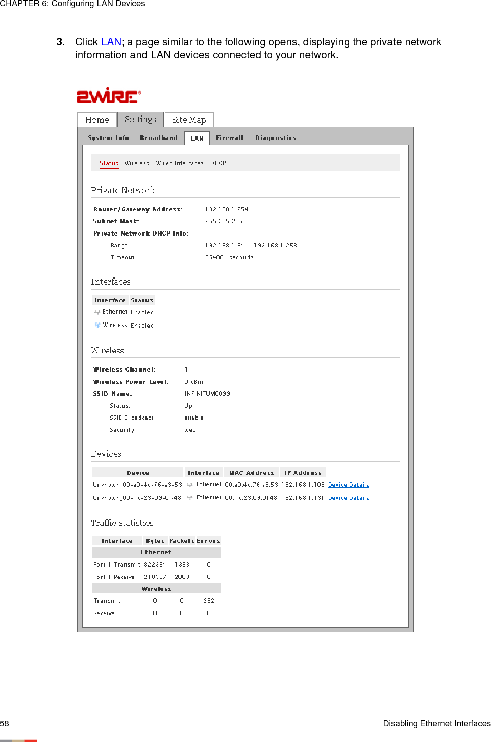
Contents
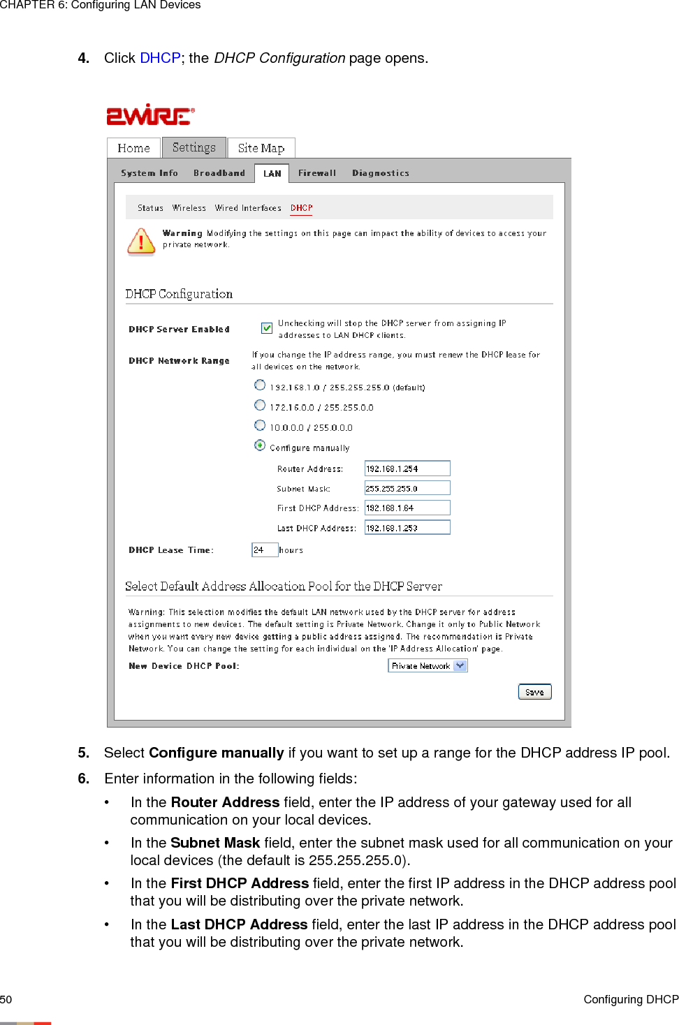
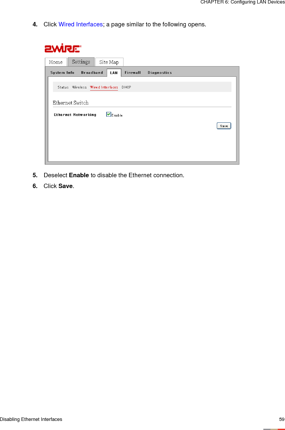
- 1. Installation and User Guide
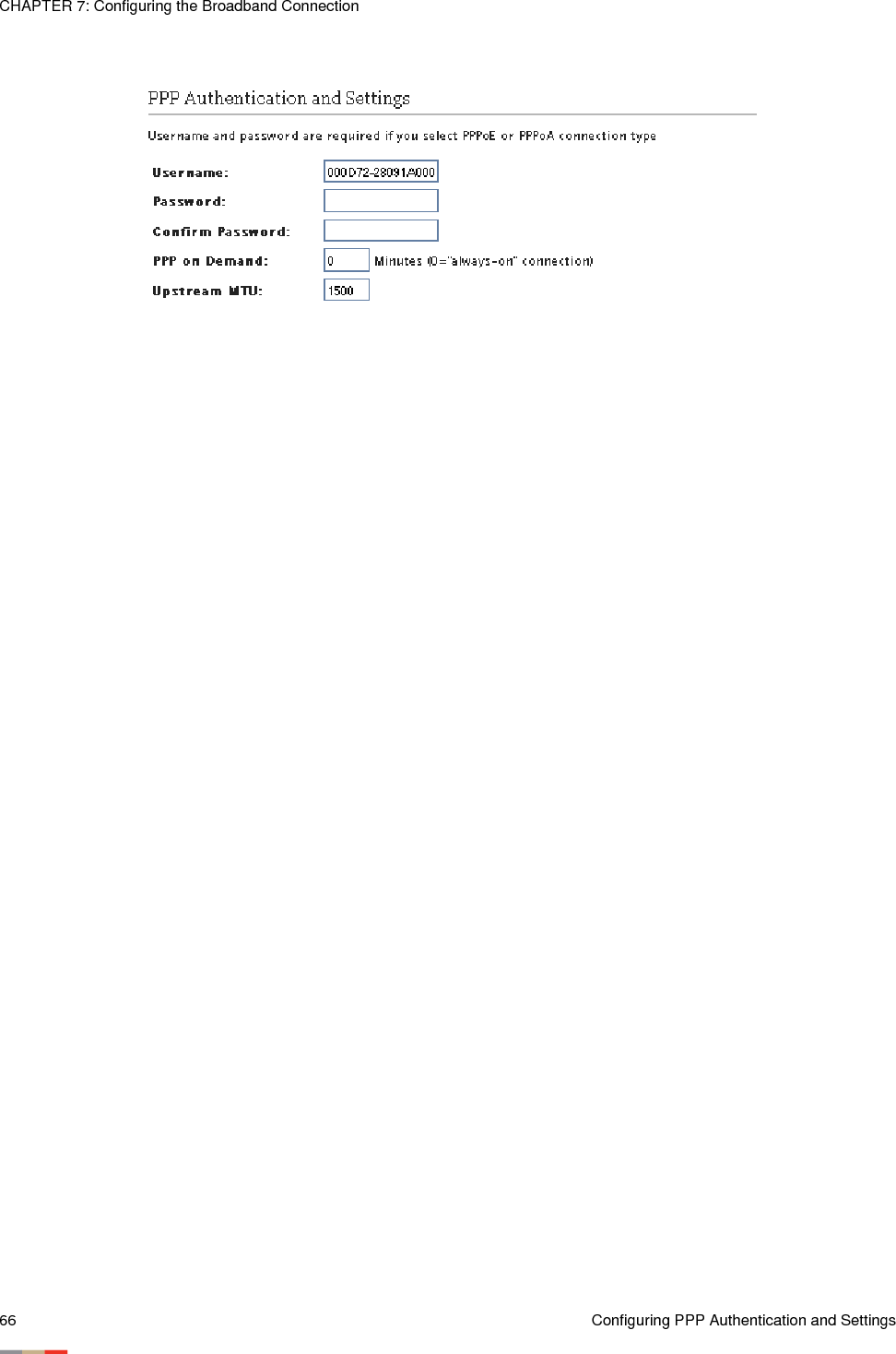
- 2. Regulatory Insert
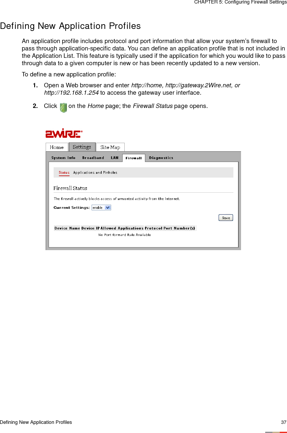
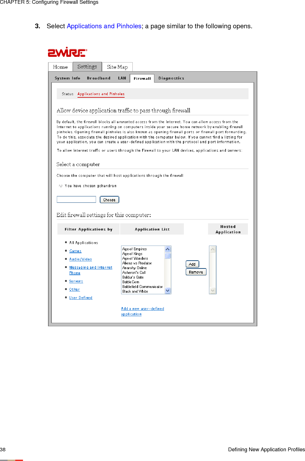
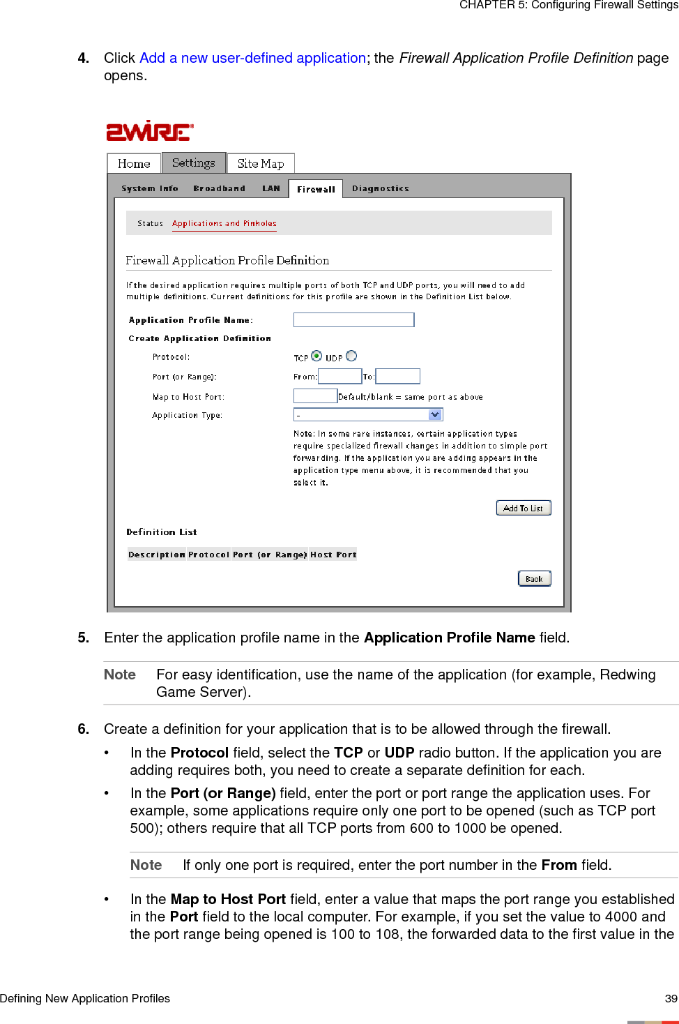
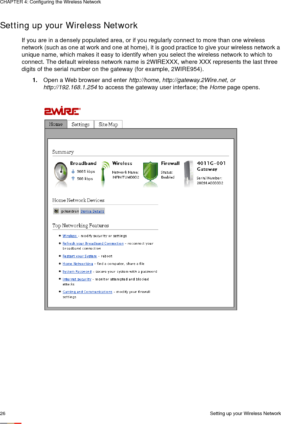
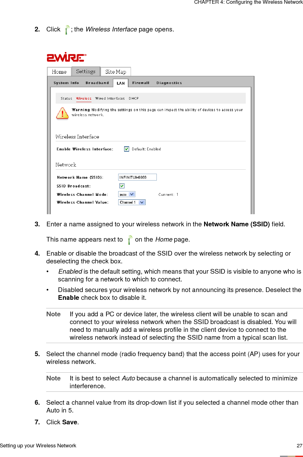
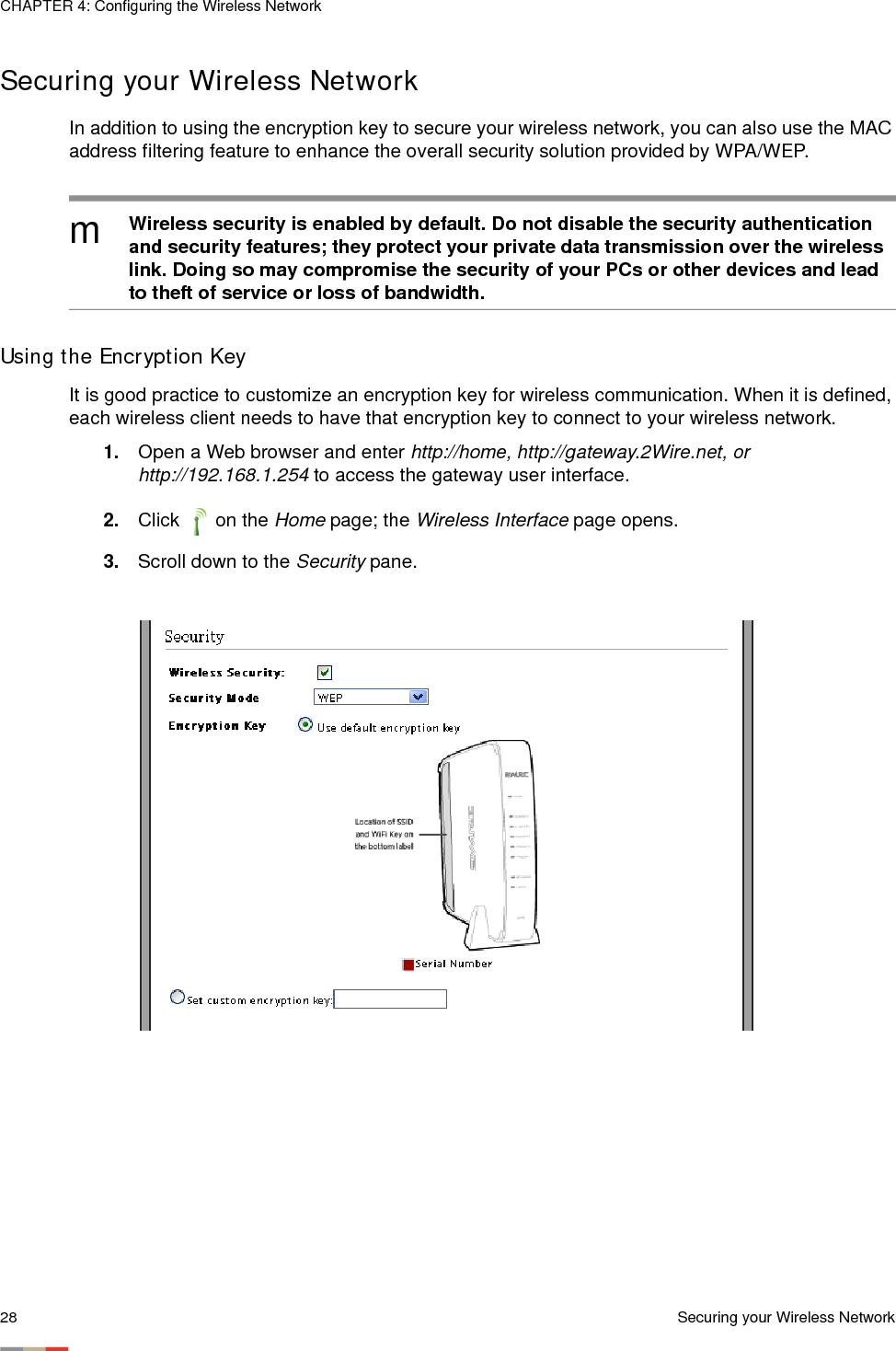
Installation and User Guide
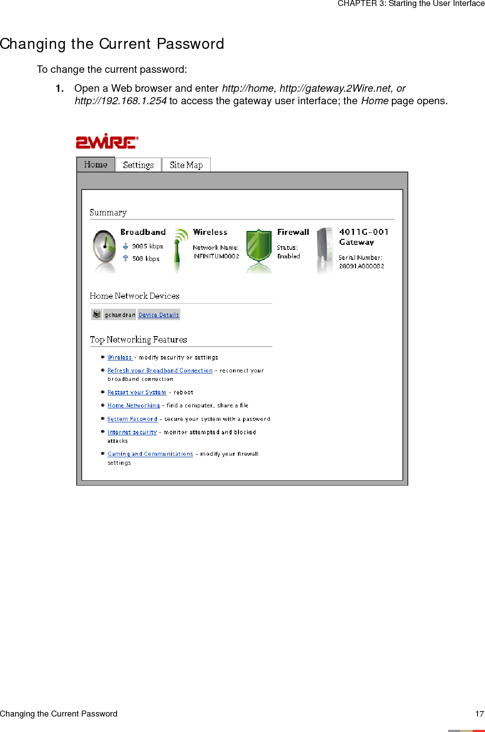
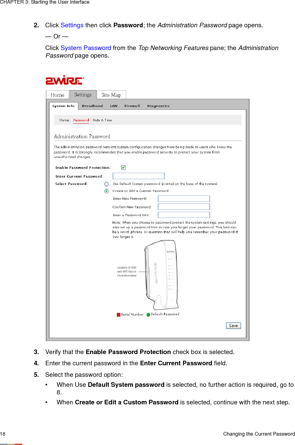
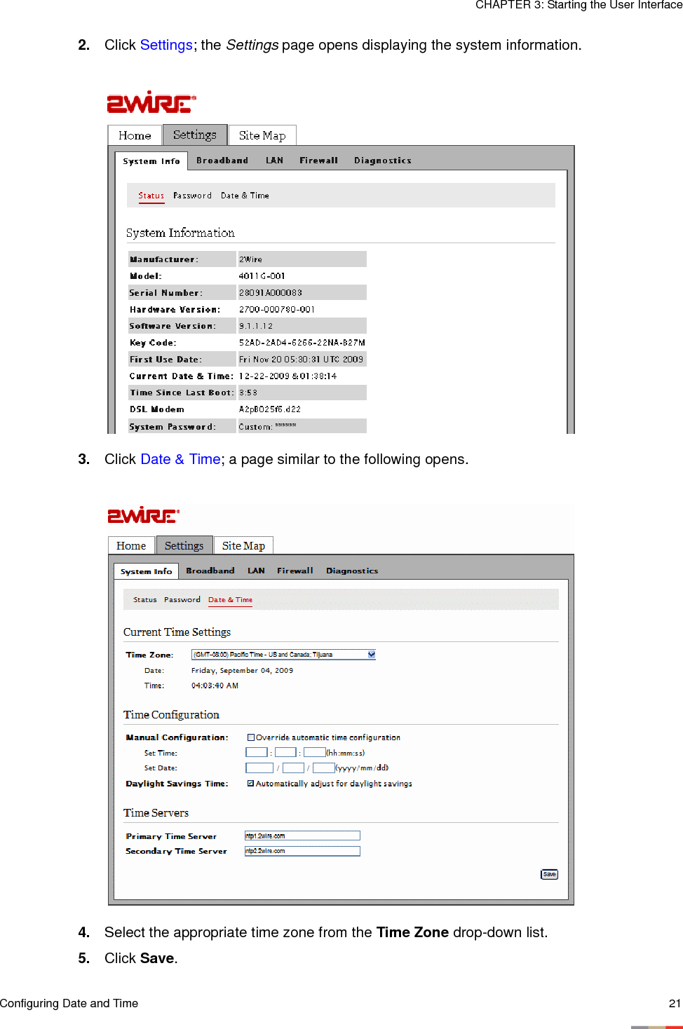

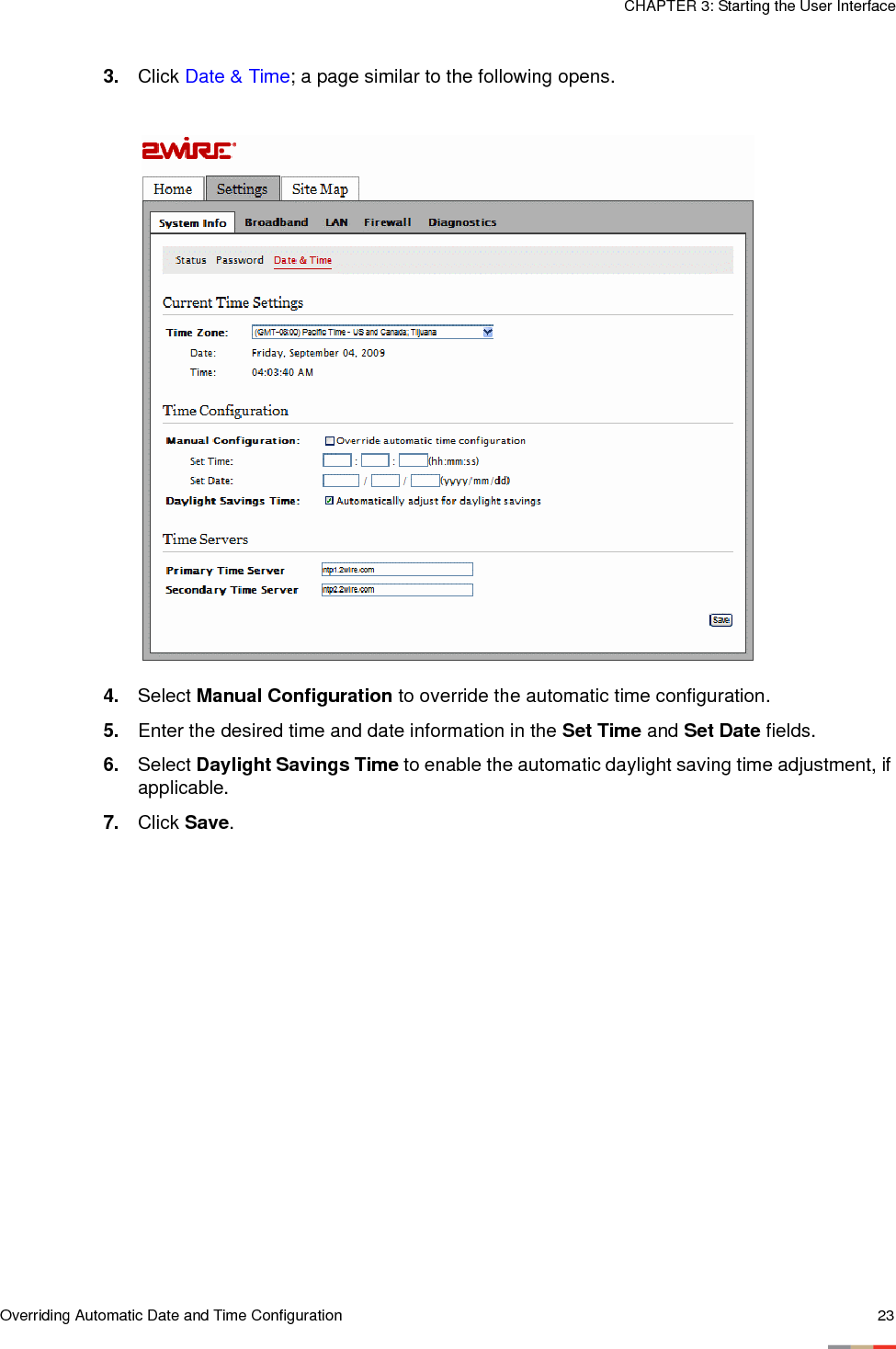
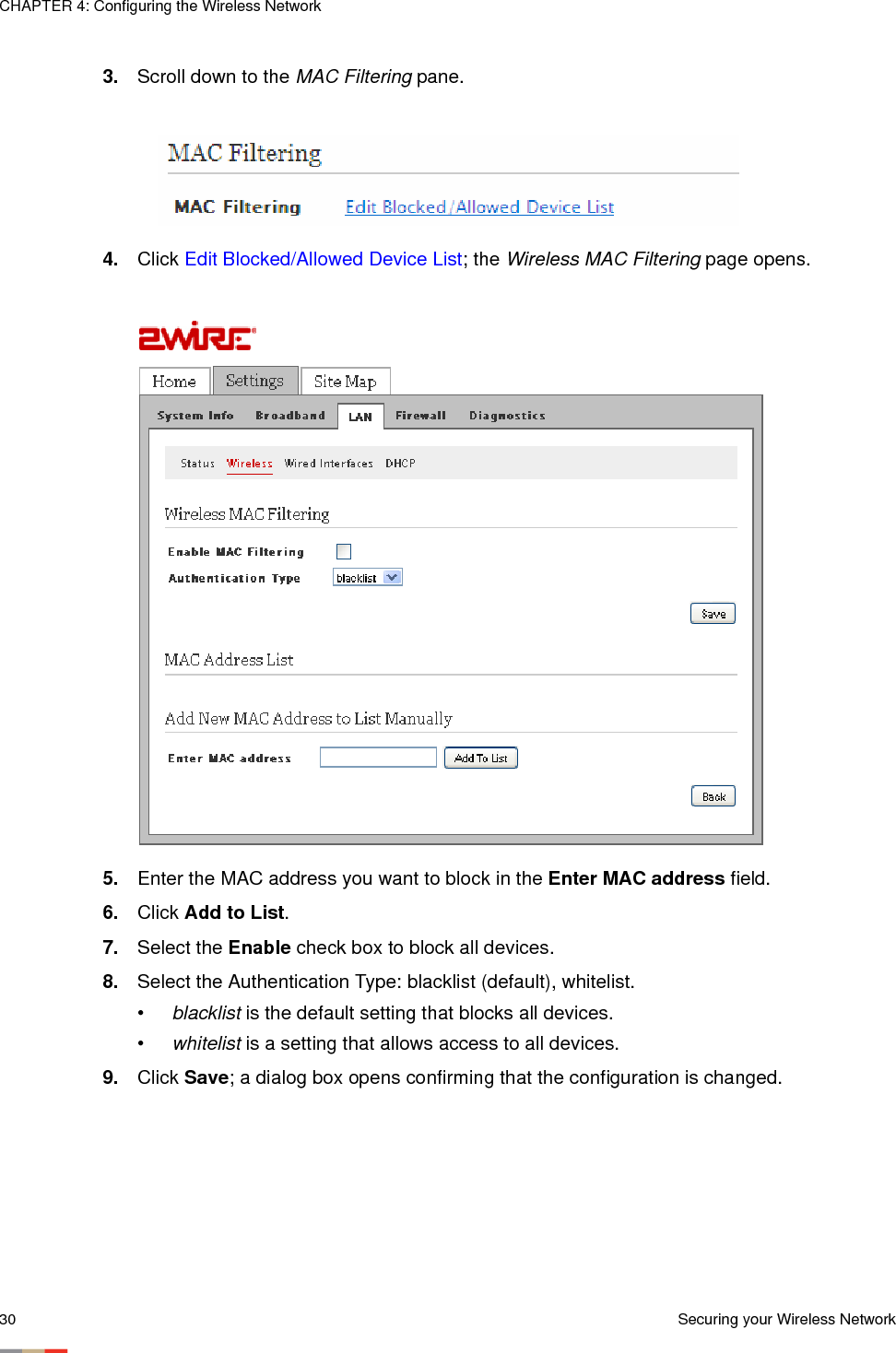
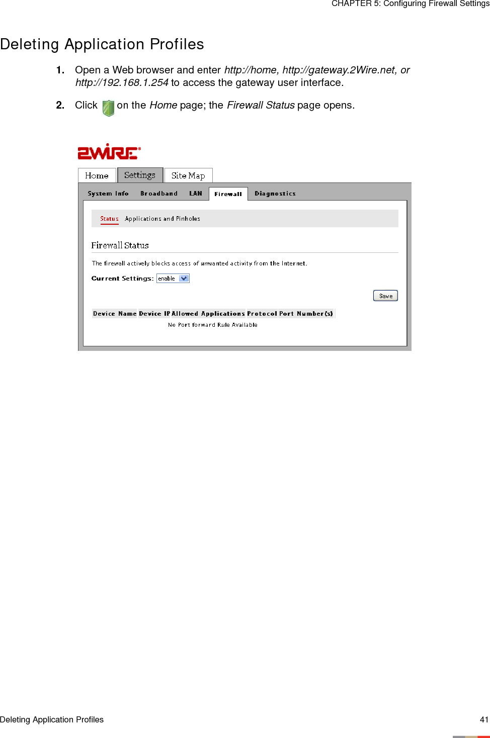
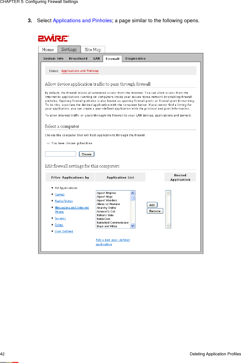
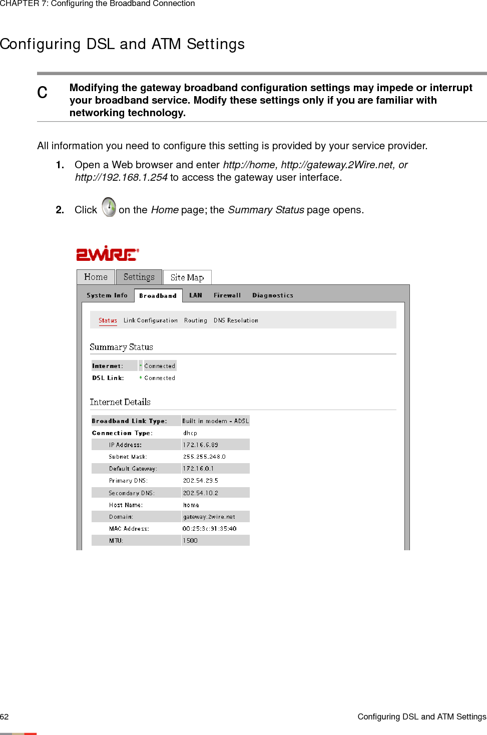
![Removing Hosted Applications 35CHAPTER 5: Configuring Firewall SettingsNote To select multiple applications, hold down the [Shift] or [Ctrl] keys while making your selections. Using the [Shift] key lets you make your selections in a contiguous order while the [Ctrl] key selects the groups in a random order.7. Click Add; the application(s) you selected appears in the Hosted Applications panel. Removing Hosted Applications1. Open a Web browser and enter http://home, http://gateway.2Wire.net, or http://192.168.1.254 to access the gateway user interface. 2. Click on the Home page; the Firewall Status page opens, displaying the current hosted application settings.3. Select Applications and Pinholes; a page opens showing the current hosted applications.](https://usermanual.wiki/ARRIS/2W4011G.Installation-and-User-Guide/User-Guide-1239478-Page-39.png)
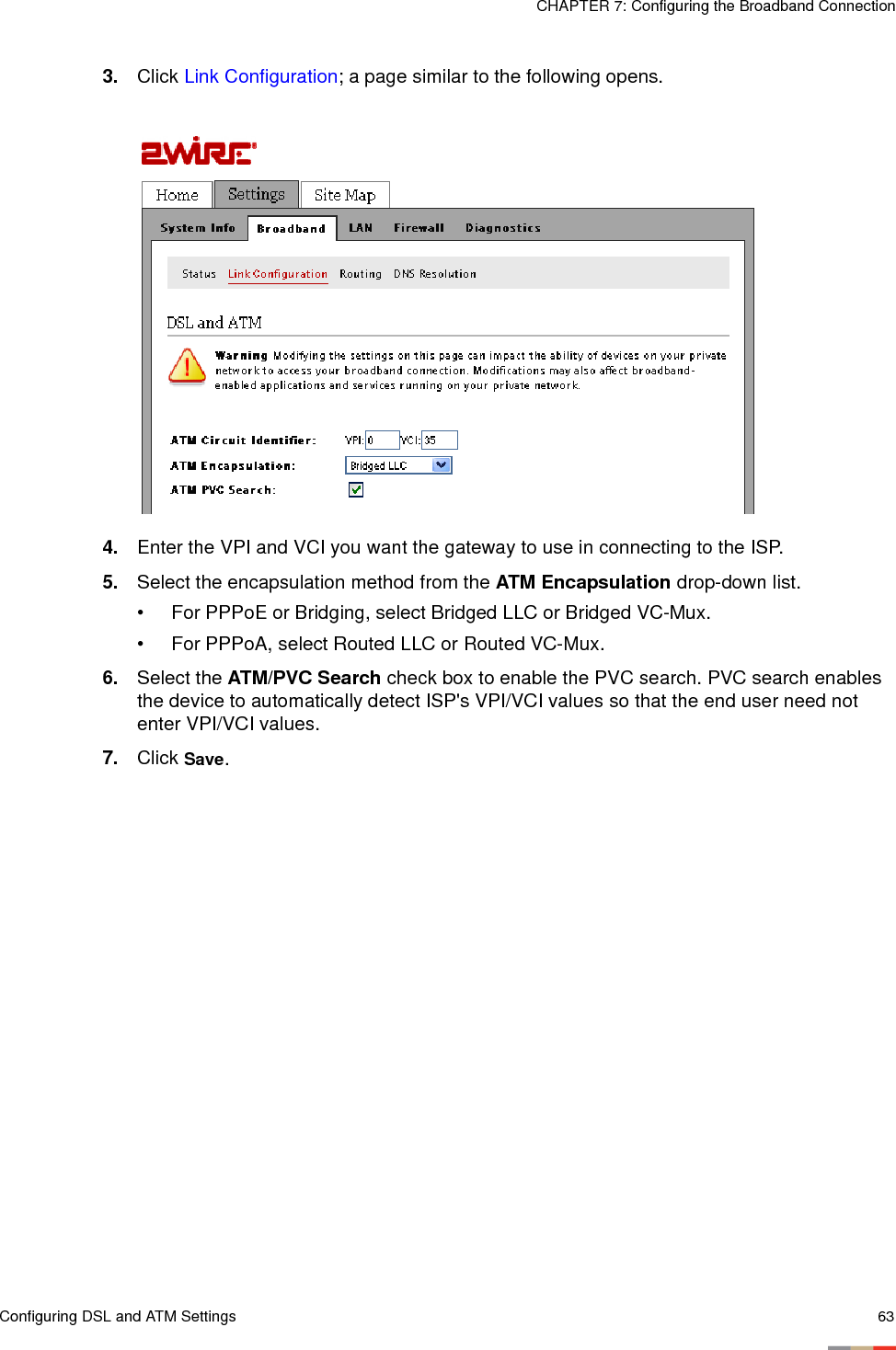
![CHAPTER 5: Configuring Firewall Settings36 Removing Hosted Applications4. Select the application(s) you want to remove from the Hosted Applications panel, click Remove.Note To select multiple applications, hold down the [Shift] or [Ctrl] keys while making your selections. Using the [Shift] key lets you make your selections in a contiguous order while the [Ctrl] key selects the groups in a random order.5. Click Save; a message appears informing you of the status. The application(s) you selected is removed from the Hosted Applications panel and returned to the Application List panel.](https://usermanual.wiki/ARRIS/2W4011G.Installation-and-User-Guide/User-Guide-1239478-Page-40.png)