ARRIS 2W4011G Wireless 802.11g ADSL Residential Gateway User Manual 4011G Gateway Installation and User Guide
Pace Americas Wireless 802.11g ADSL Residential Gateway 4011G Gateway Installation and User Guide
ARRIS >
Contents
- 1. Installation and User Guide
- 2. Regulatory Insert
Installation and User Guide

Gateway Installation and User Guide
4011G
Version 9.1.1 Rev. 001

Notice to Users
©2005–2009 2Wire, Inc. All rights reserved. This manual in whole or in part, may not be reproduced, translated, or reduced to any
machine-readable form without prior written approval.
2WIRE PROVIDES NO WARRANTY WITH REGARD TO THIS MANUAL, THE SOFTWARE, OR OTHER INFORMATION
CONTAINED HEREIN AND HEREBY EXPRESSLY DISCLAIMS ANY IMPLIED WARRANTIES OF MERCHANTABILITY OR
FITNESS FOR ANY PARTICULAR PURPOSE WITH REGARD TO THIS MANUAL, THE SOFTWARE, OR SUCH OTHER
INFORMATION, IN NO EVENT SHALL 2WIRE, INC. BE LIABLE FOR ANY INCIDENTAL, CONSEQUENTIAL, OR SPECIAL
DAMAGES, WHETHER BASED ON TORT, CONTRACT, OR OTHERWISE, ARISING OUT OF OR IN CONNECTION WITH THIS
MANUAL, THE SOFTWARE, OR OTHER INFORMATION CONTAINED HEREIN OR THE USE THEREOF.
2Wire, Inc. reserves the right to make any modification to this manual or the information contained herein at any time without notice.
The software described herein is governed by the terms of a separate user license agreement.
Updates and additions to software may require an additional charge. Subscriptions to online service providers may require a fee and
credit card information. Financial services may require prior arrangements with participating financial institutions.
2Wire, the 2Wire logo, HomePortal, and MediaPortal are registered trademarks of 2Wire, Inc. All other trademarks are trademarks of
their respective owners.
12222009
5100-000764-000

iii
Contents
CHAPTER 1 Presenting the 4011G Gateway . . . . . . . . . . . . . . . . . . . . . . . . . . . . . . . . . . . . . . . 1
CHAPTER 2 Installing Your Gateway . . . . . . . . . . . . . . . . . . . . . . . . . . . . . . . . . . . . . . . . . . . . . 3
Determining a Wireless Access Point Location. . . . . . . . . . . . . . . . . . . . . . . . . . . . . . . . .4
Avoiding Interference . . . . . . . . . . . . . . . . . . . . . . . . . . . . . . . . . . . . . . . . . . . . . . . .4
Avoiding Obstructions . . . . . . . . . . . . . . . . . . . . . . . . . . . . . . . . . . . . . . . . . . . . . . . .4
Installing the DSL Filter . . . . . . . . . . . . . . . . . . . . . . . . . . . . . . . . . . . . . . . . . . . . . . . . . . .4
Connecting the Power Adapter . . . . . . . . . . . . . . . . . . . . . . . . . . . . . . . . . . . . . . . . . . . . .6
Connecting the Phone Line. . . . . . . . . . . . . . . . . . . . . . . . . . . . . . . . . . . . . . . . . . . . . . . .7
Connecting Your Computer to the Gateway . . . . . . . . . . . . . . . . . . . . . . . . . . . . . . . . . . .7
Connecting via Ethernet Ports . . . . . . . . . . . . . . . . . . . . . . . . . . . . . . . . . . . . . . . . . .7
Connecting via Wireless . . . . . . . . . . . . . . . . . . . . . . . . . . . . . . . . . . . . . . . . . . . . . .8
Configuring Wireless Adapters . . . . . . . . . . . . . . . . . . . . . . . . . . . . . . . . . . . . . . . . . . . . .8
Starting Your Gateway. . . . . . . . . . . . . . . . . . . . . . . . . . . . . . . . . . . . . . . . . . . . . . . . . . . .9
CHAPTER 3 Starting the User Interface . . . . . . . . . . . . . . . . . . . . . . . . . . . . . . . . . . . . . . . . . . 11
Navigating the User Interface . . . . . . . . . . . . . . . . . . . . . . . . . . . . . . . . . . . . . . . . . . . . .11
Setting up Your Password . . . . . . . . . . . . . . . . . . . . . . . . . . . . . . . . . . . . . . . . . . . . . . . .14
Changing the Current Password . . . . . . . . . . . . . . . . . . . . . . . . . . . . . . . . . . . . . . . . . . .17
Configuring Date and Time . . . . . . . . . . . . . . . . . . . . . . . . . . . . . . . . . . . . . . . . . . . . . . .20
Overriding Automatic Date and Time Configuration . . . . . . . . . . . . . . . . . . . . . . . . . . . .22
CHAPTER 4 Configuring the Wireless Network . . . . . . . . . . . . . . . . . . . . . . . . . . . . . . . . . . . . 25
Setting up your Wireless Network . . . . . . . . . . . . . . . . . . . . . . . . . . . . . . . . . . . . . . . . . .26
Securing your Wireless Network . . . . . . . . . . . . . . . . . . . . . . . . . . . . . . . . . . . . . . . . . . .28
Using the Encryption Key . . . . . . . . . . . . . . . . . . . . . . . . . . . . . . . . . . . . . . . . . . . .28
Using the MAC Address Filtering . . . . . . . . . . . . . . . . . . . . . . . . . . . . . . . . . . . . . .29
Customize Private Wireless Settings . . . . . . . . . . . . . . . . . . . . . . . . . . . . . . . . . . . . . . .31
CHAPTER 5 Configuring Firewall Settings. . . . . . . . . . . . . . . . . . . . . . . . . . . . . . . . . . . . . . . . 33
Hosting Applications . . . . . . . . . . . . . . . . . . . . . . . . . . . . . . . . . . . . . . . . . . . . . . . . . . . .33
Removing Hosted Applications . . . . . . . . . . . . . . . . . . . . . . . . . . . . . . . . . . . . . . . . . . . .35
Defining New Application Profiles . . . . . . . . . . . . . . . . . . . . . . . . . . . . . . . . . . . . . . . . . .37
Deleting Application Profiles . . . . . . . . . . . . . . . . . . . . . . . . . . . . . . . . . . . . . . . . . . . . . .41
CHAPTER 6 Configuring LAN Devices . . . . . . . . . . . . . . . . . . . . . . . . . . . . . . . . . . . . . . . . . . . 45
Adding New Static Routes. . . . . . . . . . . . . . . . . . . . . . . . . . . . . . . . . . . . . . . . . . . . . . . .46
Configuring DHCP. . . . . . . . . . . . . . . . . . . . . . . . . . . . . . . . . . . . . . . . . . . . . . . . . . . . . .47
Allocating an Address Pool for All Devices . . . . . . . . . . . . . . . . . . . . . . . . . . . . . . . . . . .52
Disabling Ethernet Interfaces . . . . . . . . . . . . . . . . . . . . . . . . . . . . . . . . . . . . . . . . . . . . .56

iv
Contents
CHAPTER 7 Configuring the Broadband Connection . . . . . . . . . . . . . . . . . . . . . . . . . . . . . . . 61
Configuring DSL and ATM Settings . . . . . . . . . . . . . . . . . . . . . . . . . . . . . . . . . . . . . . . .62
Configuring the Connection Type . . . . . . . . . . . . . . . . . . . . . . . . . . . . . . . . . . . . . . . . . .64
Configuring PPP Authentication and Settings. . . . . . . . . . . . . . . . . . . . . . . . . . . . . . . . .65
Modifying Broadband IP Addresses . . . . . . . . . . . . . . . . . . . . . . . . . . . . . . . . . . . . . . . .67
Specifying DNS Information Manually . . . . . . . . . . . . . . . . . . . . . . . . . . . . . . . . . . . . . . .70
Overriding the System MAC Address . . . . . . . . . . . . . . . . . . . . . . . . . . . . . . . . . . . . . . .73
Changing to the Bridging Mode. . . . . . . . . . . . . . . . . . . . . . . . . . . . . . . . . . . . . . . . . . . .74
CHAPTER 8 Finding Solutions . . . . . . . . . . . . . . . . . . . . . . . . . . . . . . . . . . . . . . . . . . . . . . . . . 77
Diagnosing Connection Issues . . . . . . . . . . . . . . . . . . . . . . . . . . . . . . . . . . . . . . . . . . . .78
Recovering the Gateway Password . . . . . . . . . . . . . . . . . . . . . . . . . . . . . . . . . . . . . . . .79
Performing Broadband Link Tests . . . . . . . . . . . . . . . . . . . . . . . . . . . . . . . . . . . . . . . . . .79
Viewing the Gateway Information . . . . . . . . . . . . . . . . . . . . . . . . . . . . . . . . . . . . . . . . . .81
Viewing the Broadband Status . . . . . . . . . . . . . . . . . . . . . . . . . . . . . . . . . . . . . . . . . . . .82
Viewing the LAN Status. . . . . . . . . . . . . . . . . . . . . . . . . . . . . . . . . . . . . . . . . . . . . . . . . .85
Resetting the Gateway . . . . . . . . . . . . . . . . . . . . . . . . . . . . . . . . . . . . . . . . . . . . . . . . . .88

1
CHAPTER 1
Presenting the 4011G
Gateway
The 2Wire HomePortal® 4011G Gateway is the first point of contact between you, your service
provider, and your digital home. This all-in-one intelligent manageable device includes modem,
router, wireless access point, firewall and more.
The 2Wire 4011G Gateway supports ADSL, ADSL2, and ADSL2+ technology. It is available with a
single Ethernet LAN port or an optional four Ethernet LAN ports and an 802.11b/g wireless
interface. The 2Wire 4011G Gateway includes an array of the most common home networking
technologies accommodating a variety of environments.
Setting up the 4011G Gateway is simple; it requires no complicated installation. Within minutes of
unpacking the shipping box and connecting several color-coded cables, you can immediately
access the Internet.

CHAPTER 1: Presenting the 4011G Gateway
2
This page is intentionally left blank.
3
CHAPTER 2
Installing Your Gateway
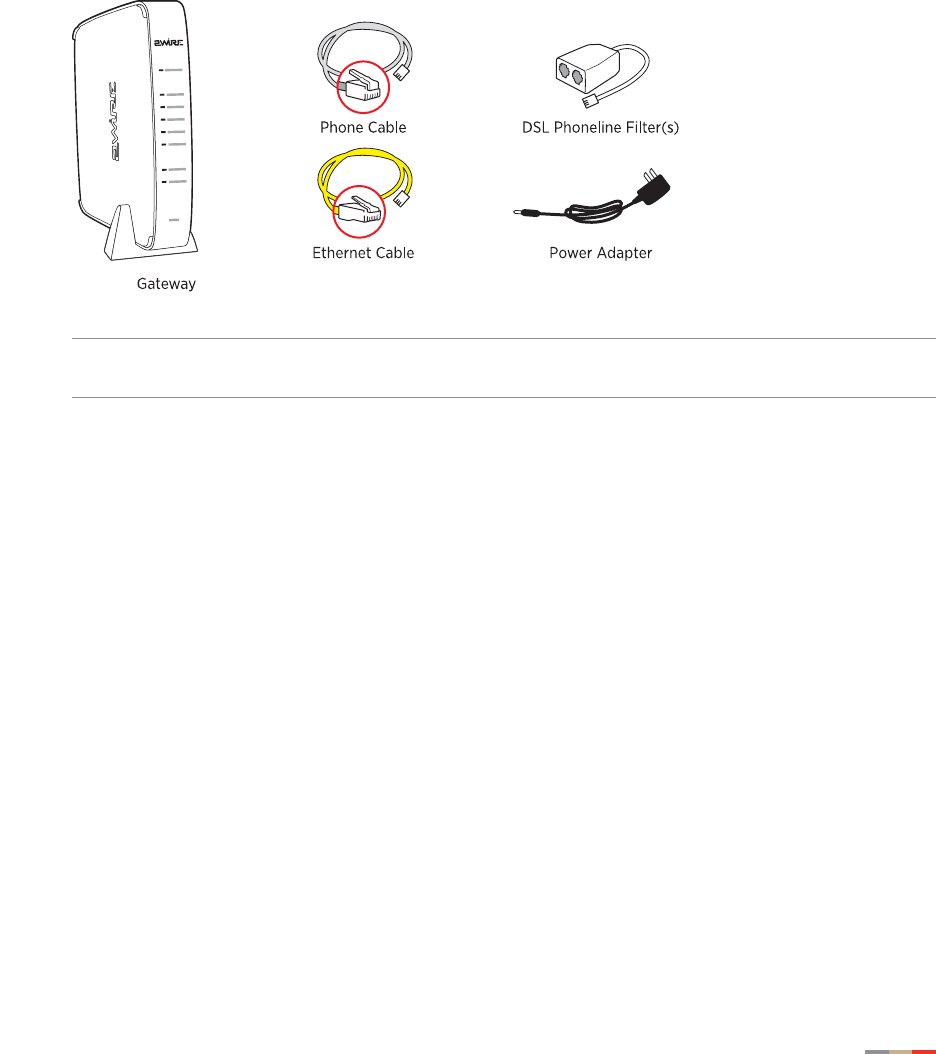
Before installing your gateway, review the package content and ensure that you have items
available as shown below.
Note The gateway and the stand are packaged separately in the container. You should place
the gateway on the stand.
Installing your gateway consists of the following tasks:
•Determining a Wireless Access Point Location on page 4
•Installing the DSL Filter on page 4
•Connecting the Power Adapter on page 6
•Connecting the Phone Line on page 7
•Connecting Your Computer to the Gateway on page 7
•Configuring Wireless Adapters on page 8
•Starting Your Gateway on page 9

CHAPTER 2: Installing Your Gateway
4Determining a Wireless Access Point Location
Determining a Wireless Access Point Location
Wireless signals are affected by many items in common households. Reliability and performance
are the major considerations when planning your wireless network location.
Avoiding Interference
Wireless signals are subject to interference from other electronic devices including (but not limited
to) microwave ovens, cordless telephones, and garage door openers. Proper installation will
minimize interference. Place your gateway at least 5 feet (1.52 meters) from cordless phones,
microwaves, or other electronic devices to avoid potential interference, and more than 6 inches
(15.24 centimeters) away from television to avoid audio hissing or static.
Note Whenever possible, use the stand provided with the gateway and install it in the vertical
position. If that is not possible, be sure that it is installed in a manner that nothing can be
stacked on the top of it.
Avoiding Obstructions
The wireless signal degrades with distance and obstructions (such as ceilings, walls, and
furniture). Consider the layout of your home or business when deciding where to place your
gateway.
• Consider where you will use your wireless devices when placing your gateway. In a single-
story building, place the gateway as high and as close to each wireless computer as
possible. To minimize interference, do not place the gateway behind large objects or other
obstructions.
• Place the gateway in an open area where wireless range will not be directly affected by
surroundings. Wireless signal strength will be much stronger in an open area as opposed
to an area with obstructions.
• Keep the gateway away from any large metal objects. Because metal objects can reflect
or obstruct signals, wireless signal quality and speed may be adversely impacted.
Installing the DSL Filter
Regular telephone and Digital Subscriber Line (DSL) signals are carried over the same line.
Converting your regular telephone line to DSL can cause high-pitched tones and static when using
the phone. Installing a filter on every telephone or telephone device sharing the same telephone
number as your DSL separates these signals and eliminates the noise.
Note Do not install DSL filters if your telephone line is only carrying a DSL signal.
Installing the DSL Filter 5
CHAPTER 2: Installing Your Gateway
You need one DSL Phoneline filter for each telephone device (desktop phone, analog modem,
FAX, or answering machine). If you have several telephone devices connected to each other and
are using a single telephone wall jack, install only one filter, connecting it between the wall jack
and the first device in the series.
Note Do not connect a 2Wire DSL Phoneline filter to an ADSL modem or to a home phoneline
network adapter. The filter blocks access to the phone line for these devices.
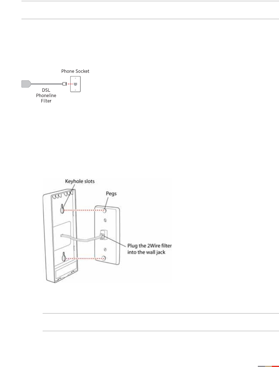
For an Individual Device
To install the DSL Phoneline filter, simply connect the cable from your telephone device to the
2Wire DSL Phoneline filter, then connect the cable from the filter to your telephone wall outlet.
For Wall-Mounted Telephones
To install the filter between the original wall plate and your wall-mounted phone:
1. Lift the telephone from the wall pegs, and disconnect the phone cord from the wall jack.
2. Connect the phone cord from the back of the 2Wire DSL filter into the wall jack, and mount
the filter on the wall plate pegs.
3. Connect the phone cord to the phone jack located on the front of the mounted 2Wire DSL
filter.
Note If you have a DSL modem, you can connect it to the phone jack located at the
bottom of the filter.
CHAPTER 2: Installing Your Gateway
6Connecting the Power Adapter
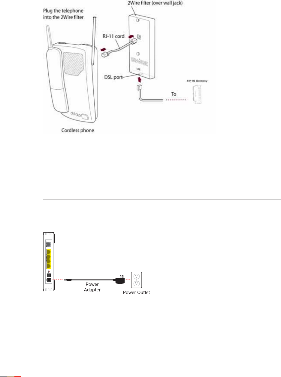
4. Attach the telephone to the mounting pegs on the 2Wire DSL filter and your installation is
complete.
Connecting the Power Adapter
1. Connect one end of the power adapter to the POWER port of your gateway.
2. Connect the other end of power adapter to an electrical outlet.
Note You can use an AC extension cord provided it is compliant to local regulatory
requirements.
Connecting the Phone Line 7
CHAPTER 2: Installing Your Gateway
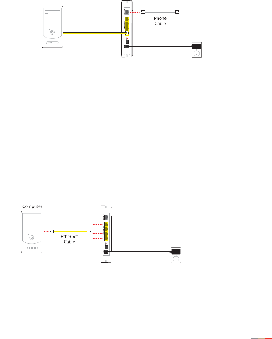
Connecting the Phone Line
1. Connect one end of the telephone line (gray) to the PHONE LINE port of your gateway.
2. Connect the other end of the telephone line to the DSL Phoneline filter if one is used, or to
the telephone wall outlet.
Connecting Your Computer to the Gateway
There are two ways to connect your computer to the gateway: via Ethernet or Wireless. With either
connection, the first computer you connect to the network is used to configure the gateway for
proper operation.
Connecting via Ethernet Ports
You can directly connect up to four computers to the gateway using the Ethernet connection.
Connect one end of the Ethernet cable (yellow) to any available ETHERNET port (yellow) on the
gateway and the other end to the computer's Ethernet port.
You are now ready to start your gateway.
Note A 6-foot Ethernet cable is provided with your gateway. Use a CAT5 RJ-45 cable if you
need additional or longer Ethernet cable.
CHAPTER 2: Installing Your Gateway
8Configuring Wireless Adapters
Connecting via Wireless
Your gateway has an integrated Wi-Fi access point (AP) that enables you to connect your
wireless-enabled computers to your home network. By default, the gateway is shipped with
WEP enabled and a preconfigured network name. Refer to the Configuring the Wireless Network
section to configure your wireless network.
Most laptop computers are equipped with an internal 802.11b/g card. If your computer is not
equipped with an internal card, you can install an external wireless adapter for wireless
networking. The 2Wire wireless adapter provides a 2Wire Setup Wizard that automatically
configures it to communicate with the gateway during setup. If you are using a non-2Wire wireless
adapter, you must manually configure it to communicate with the gateway. Refer to the Configuring
Wireless Adapters section to install a wireless network adapter.
Configuring Wireless Adapters
You must manually configure the Wireless adapter to communicate with the gateway. This section
provides instructions to configure your adapter with WPA.
1. Install and configure your wireless adapter according to the manufacturer’s instructions.
2. Use the network adapter configuration software or Windows network connection wizard to
set the network name (SSID) and encryption key (WPA).
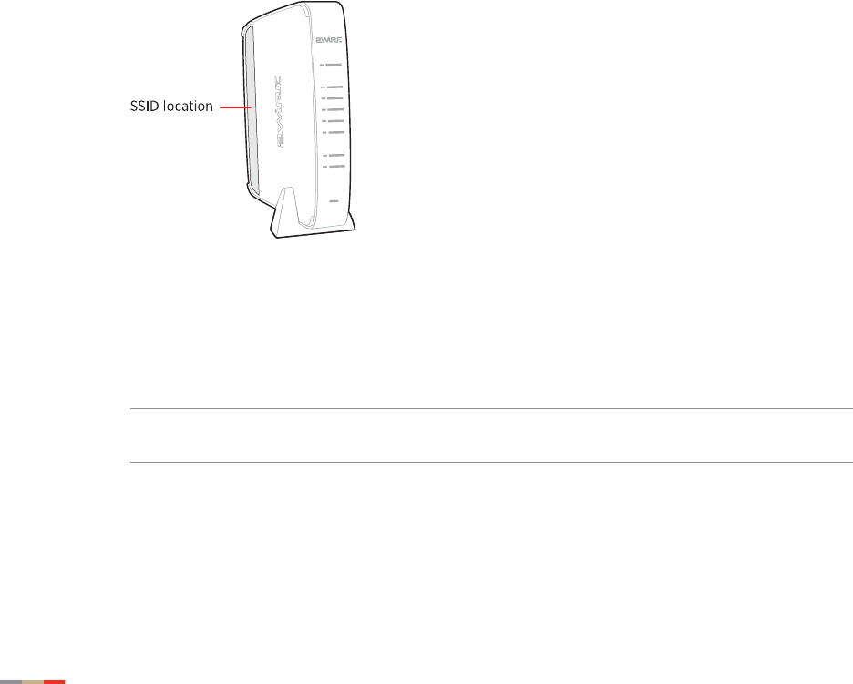
3. Enter 2WIRE (in capital letters) as the network name, followed by the last three digits of
the gateway serial number (for example, 2WIRE110), located on the bottom of your
gateway.
4. Enter the encryption key that is located inside the brackets beneath the bar code on the
bottom of your gateway, (for example, 1234567890).
Note For Mac OS X users, you may need to enter the “$” character at the beginning of
the encryption key (for example, $1234567890).
Starting Your Gateway 9
CHAPTER 2: Installing Your Gateway
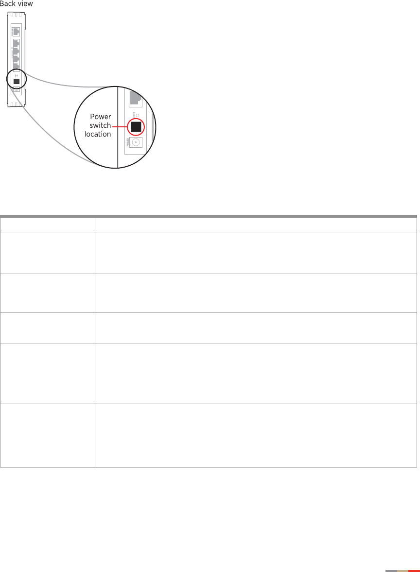
Starting Your Gateway
When cables are connected, your gateway is ready to be turned on. The POWER switch is located
on the back of the gateway. The following illustration shows the POWER switch location and the
table lists and describes the indicators when the gateway is operating under different states.
Gateway Indicators Description
Indicators Description
POWER The POWER indicator is off for a brief period of time, and then changes to solid green
within few seconds of power application.
• Constant green indicates that power is on.
• Red indicates that the gateway is faulty.
ETHERNET 1 – 4 • Solid green indicates that a device (such as a computer) is connected to an ETHERNET
port.
• Flickering green indicates that inbound activity from devices is associated with the
Ethernet port. The flickering of the light is synchronized to the actual data traffic.
WIRELESS • Solid green indicates that there is Wireless client associated to a specific Access Point.
• Flickering green indicates that there is inbound/outbound activity. The flickering of the
light is synchronized to the actual data traffic.
BROADBAND This indicator shows the gateway DSL status.
• Constant green indicates successful broadband connection and no interruption in
Internet access.
• Flashing green indicates that the gateway is attempting to establish a broadband
connection.
• Red indicates that there is no DSL signal.
SERVICE • Constant green indicates that the gateway has obtained a WAN IP address from your
service provider through the DHCP or PPP connection and the broadband connection is
up.
• Flashing green at a faster pace indicates that the gateway is attempting to obtain an IP
address.
• Flashing green at a slower pace indicates that the service provider’s network is not
responding, a misconfiguration, or an authentication failure.

CHAPTER 2: Installing Your Gateway
10 Starting Your Gateway
This page is intentionally left blank.

11
CHAPTER 3
Starting the User Interface
Verify that your computers have one of the following browsers installed:
• Microsoft Internet Explorer 5.5 or higher
• Mozilla Firefox 2.0 or higher
• Safari 2.0
Navigating the User Interface
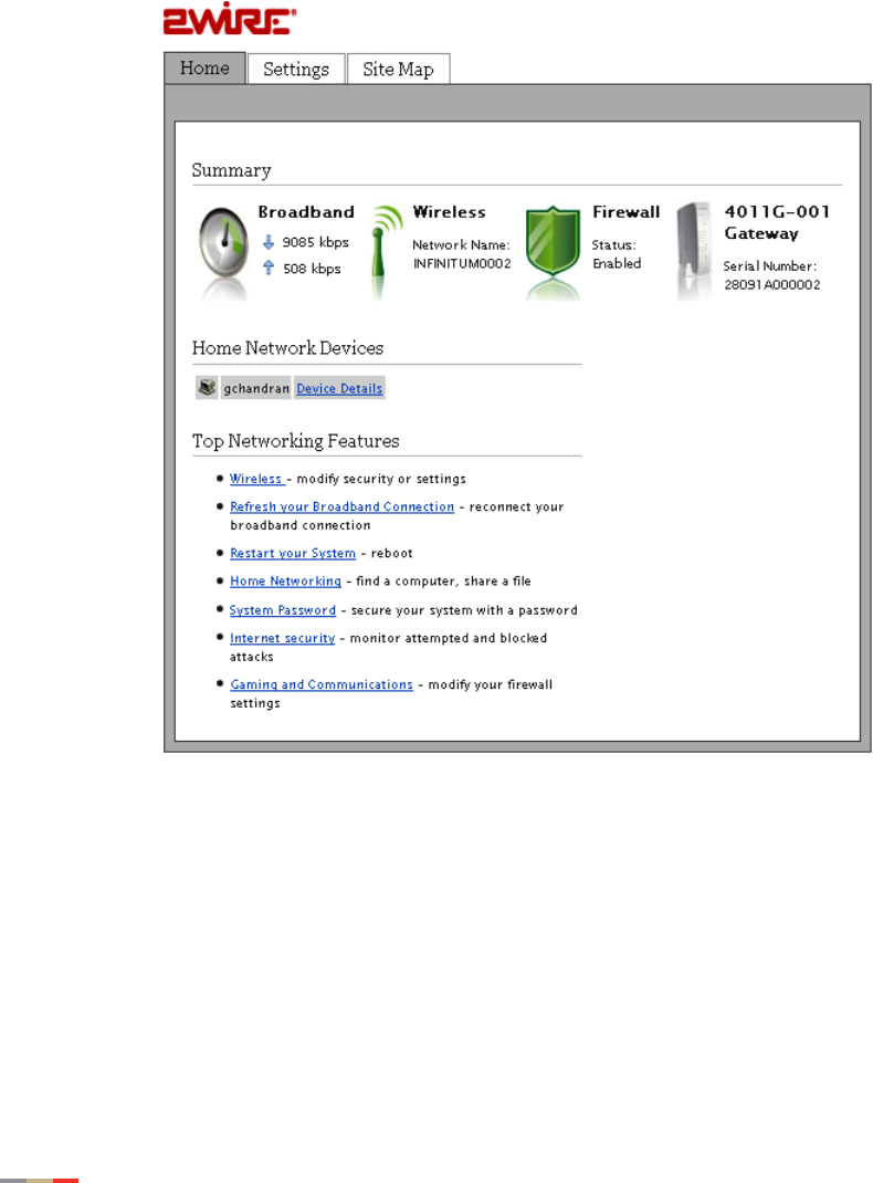
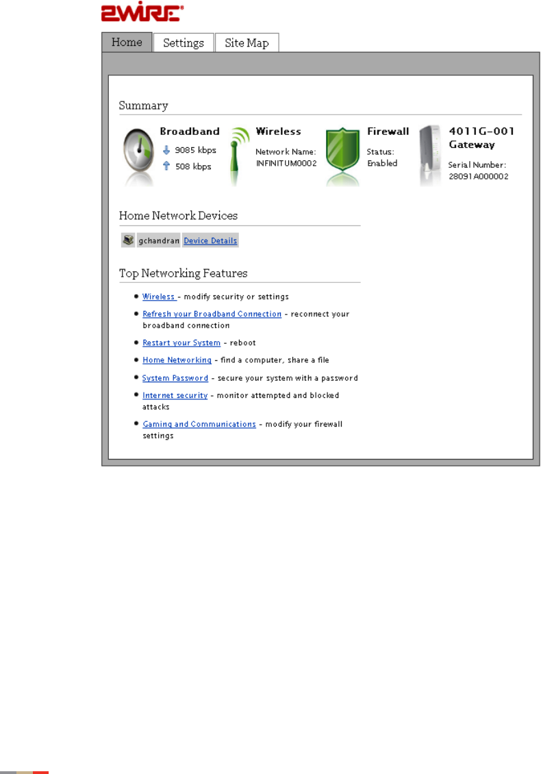
The Home page appears when you enter one of the following URLs into a compatible browser on
a computer connected to the gateway.
• http://gateway.2Wire.net
• http://home
• http://192.168.1.254
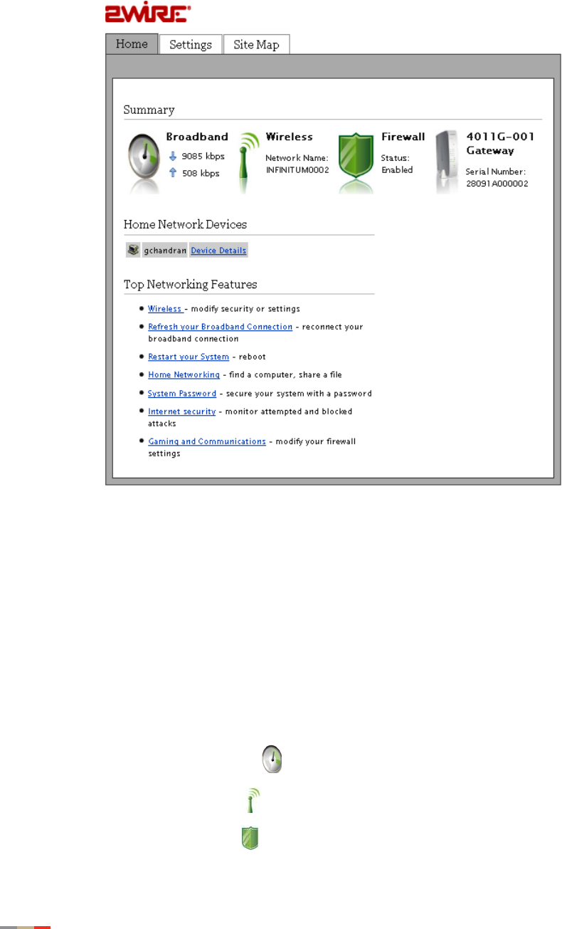
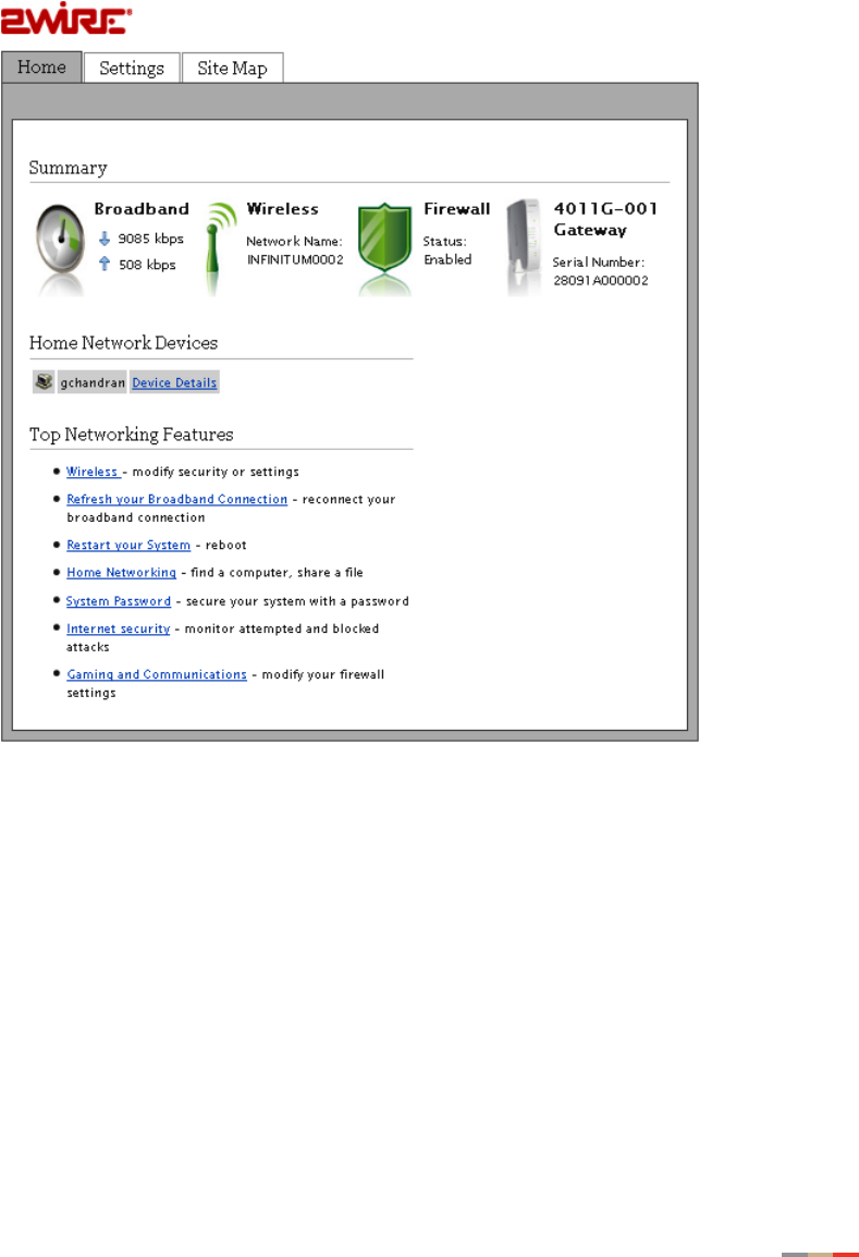
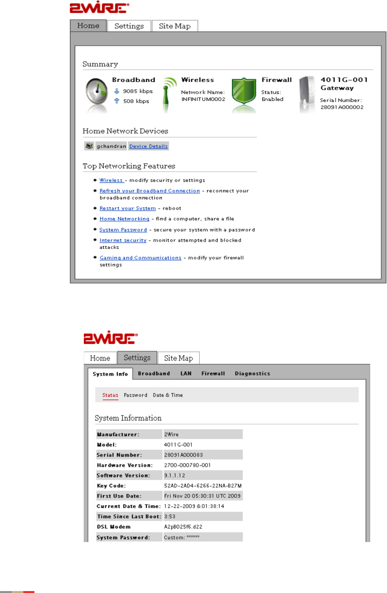
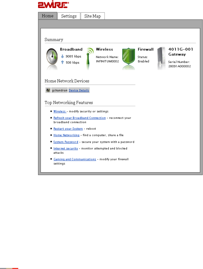
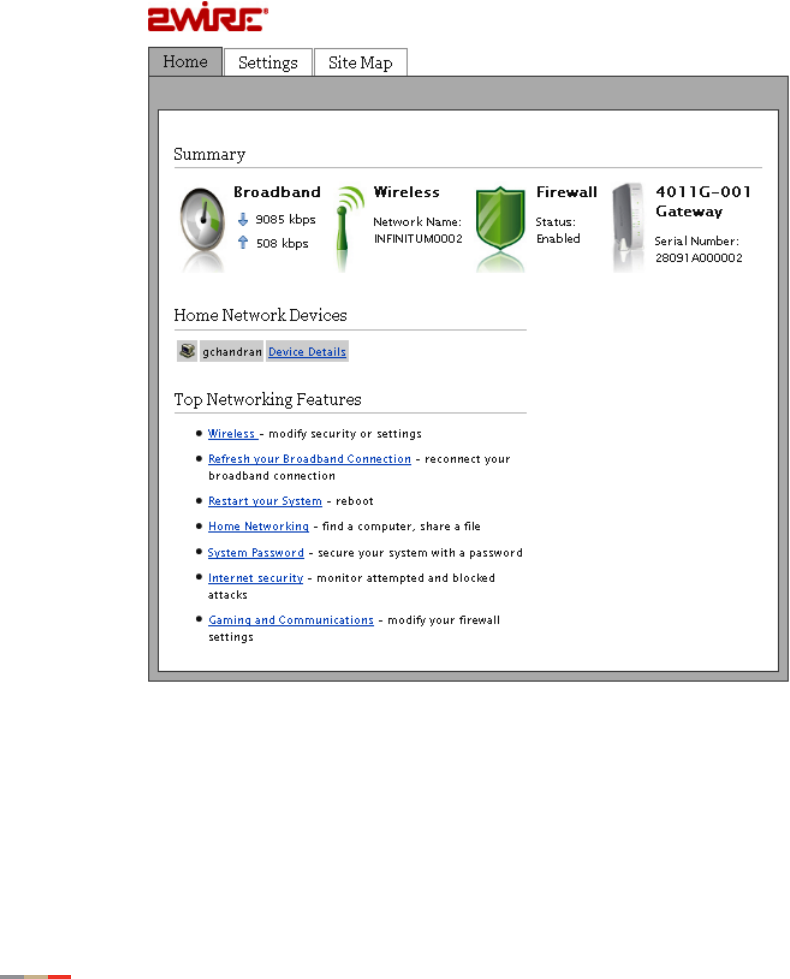
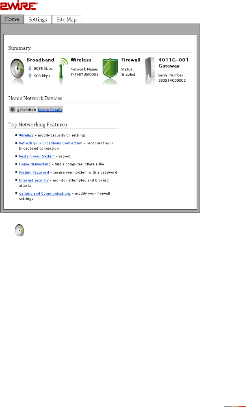
This page contains four panes. The following section describes each pane that is indicated by the
numbered red arrow.
CHAPTER 3: Starting the User Interface
12 Navigating the User Interface
1. The tab pane of the user interface contains the following three tabs that are arranged
horizontally. Clicking any of these tabs displays a page that enables you to access
associated information.
•The Home tab provides the most relevant information about your broadband service
at a glance. It also provides links to access more detailed information.
•The Settings tab provides the most comprehensive system information. Clicking this
tab opens a page that provides sub-tabs to access other pages to configure your
gateway and view system status.
•The Site Map tab provides a textual view of the user interface. Clicking any links on
this page takes you directly to the page of interest.
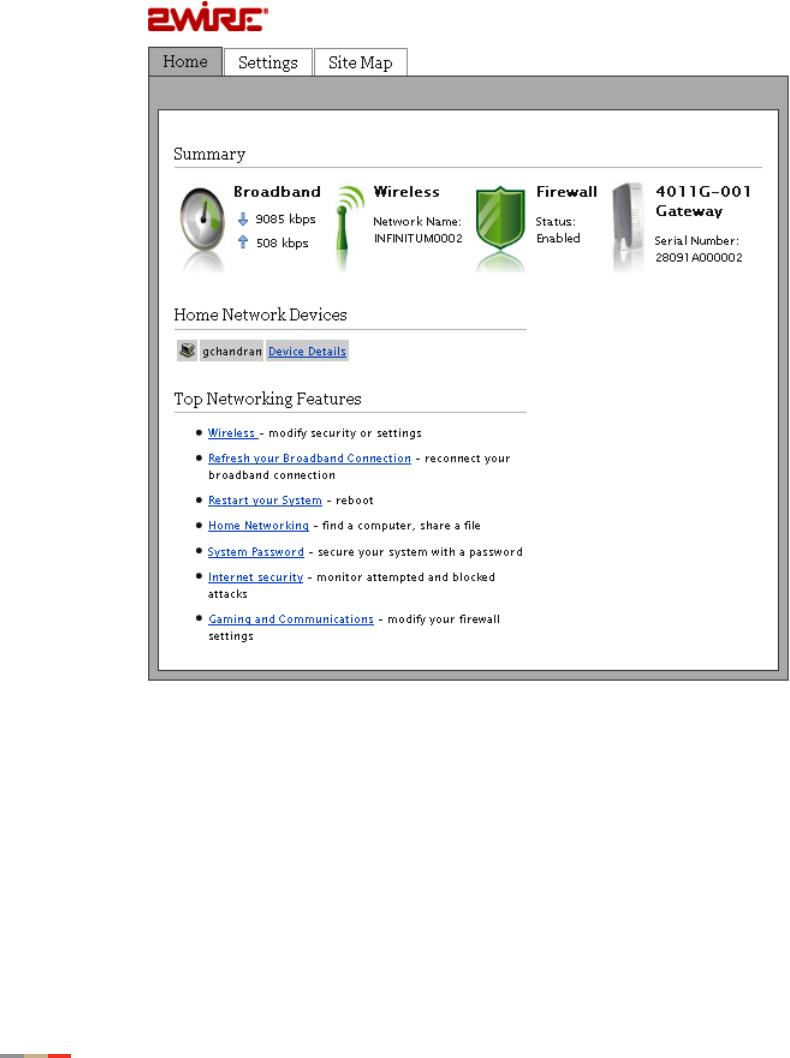
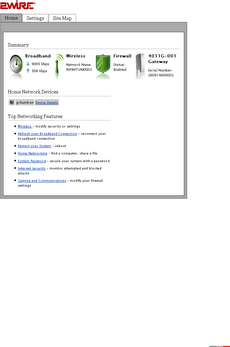
2. The Summary pane displays the status of each service. Except the fourth icon, gateway,
you can click other icons to directly access more information.
•The Broadband icon displays the Internet upload and download rates in kbps.
•The Wireless icon displays the wireless network name.
•The Firewall icon displays the current Firewall status- enabled or disabled.

Navigating the User Interface 13
CHAPTER 3: Starting the User Interface
•The 4011G Gateway icon displays the gateway device serial number.
3. The Home Network Devices pane displays all devices that are connected to the gateway.
You can click the links to view the detailed information of the connected devices.
4. The Top Networking Features pane provides shortcuts to directly access the most
commonly used pages.

CHAPTER 3: Starting the User Interface
14 Setting up Your Password
Setting up Your Password
A system password protects your gateway settings from being modified or changed by someone
who has not been given permission to do so. When a password is set up, you will be required to
enter a system password whenever you attempt to access a configuration page (for example,
when you try to change the broadband connection settings).
To set up a password:
1. Open a Web browser and enter http://home, http://gateway.2Wire.net, or
http://192.168.1.254 to access the gateway user interface; the Home page opens.
Setting up Your Password 15
CHAPTER 3: Starting the User Interface
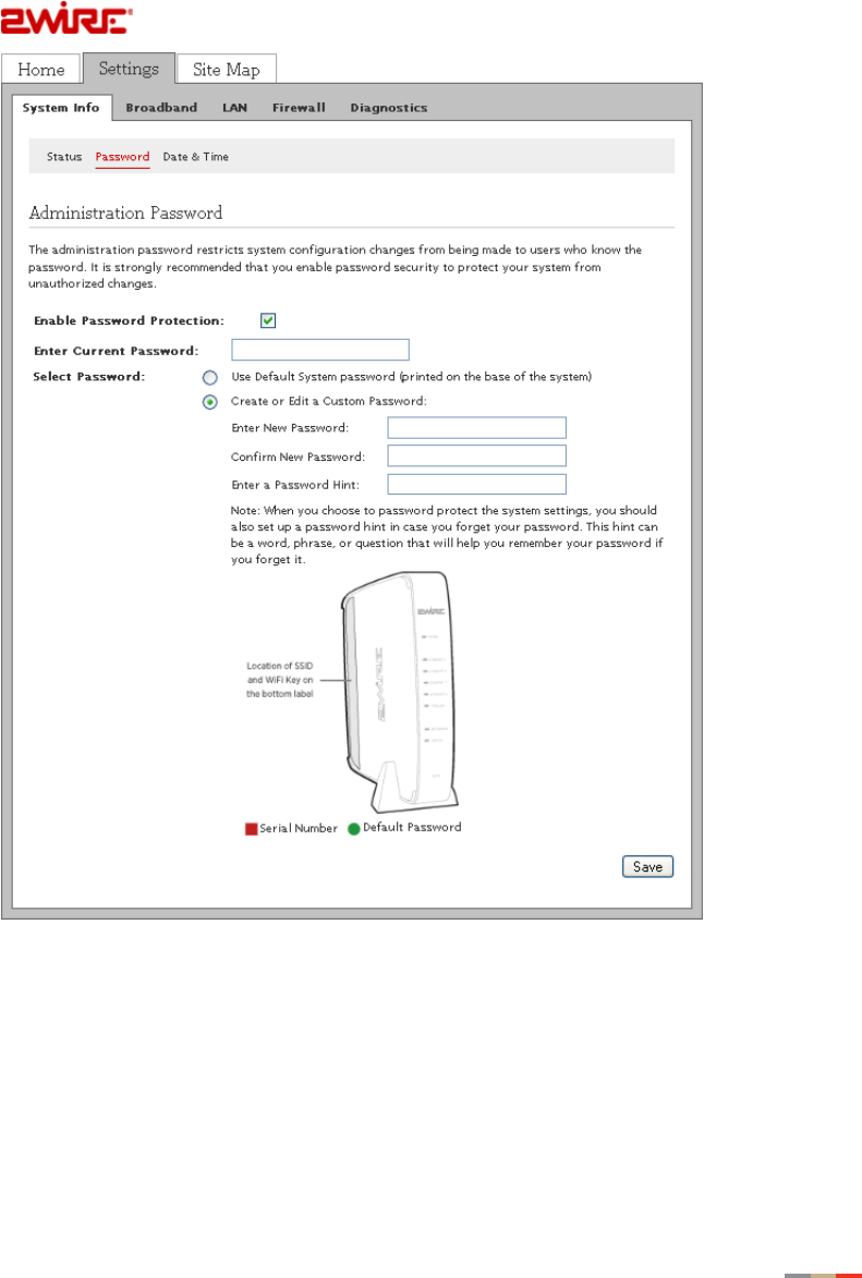
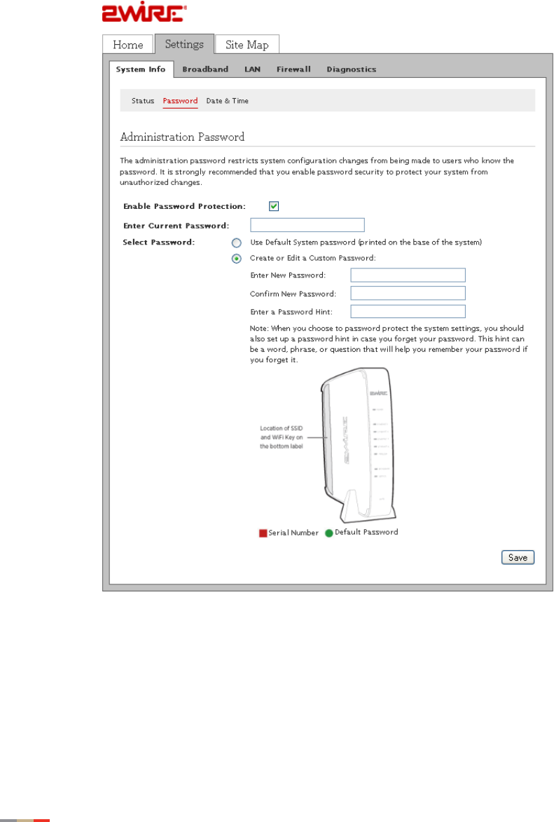
2. Click Settings then click Password; the Administration Password page opens.
— Or —
Click System Password from the Top Networking Features pane; the Administration
Password page opens.

CHAPTER 3: Starting the User Interface
16 Setting up Your Password
3. Select the Enable Password Protection check box.
Note Make sure to select this check box or your password will not save.
4. Select the password option:
• When Use Default System password is selected, no further action is required,
go to 7.
• When Create or Edit a Custom Password is selected, continue with the next step.
Note The default system password is printed on the bottom of the gateway.
5. Enter a new password having minimum 6 alphanumeric characters in the Enter New
Password field.
Note The password is case-sensitive and prompts an error message if you enter less
than 6 alphanumeric characters.
6. Re-enter the new password in Confirm New Password field.
Note Although optional, it is strongly recommended that you enter a password hint to
remind you if you forget your password.
7. Click Save; a message appears informing you of the status.
Changing the Current Password 17
CHAPTER 3: Starting the User Interface
Changing the Current Password
To change the current password:
1. Open a Web browser and enter http://home, http://gateway.2Wire.net, or
http://192.168.1.254 to access the gateway user interface; the Home page opens.
CHAPTER 3: Starting the User Interface
18 Changing the Current Password
2. Click Settings then click Password; the Administration Password page opens.
— Or —
Click System Password from the Top Networking Features pane; the Administration
Password page opens.
3. Verify that the Enable Password Protection check box is selected.
4. Enter the current password in the Enter Current Password field.
5. Select the password option:
• When Use Default System password is selected, no further action is required, go to
8.
• When Create or Edit a Custom Password is selected, continue with the next step.

Changing the Current Password 19
CHAPTER 3: Starting the User Interface
Note The default system password is printed on the bottom of the gateway.
6. Enter a new password between 5 and 31 alphanumeric characters in the Enter New
Password field.
Note The password is case-sensitive.
7. Re-enter the new password in Confirm New Password field.
Note Although optional, it is strongly recommended that you enter a password hint to
remind you if you forget your password.
8. Click Save; a message appears informing you of the status.
CHAPTER 3: Starting the User Interface
20 Configuring Date and Time
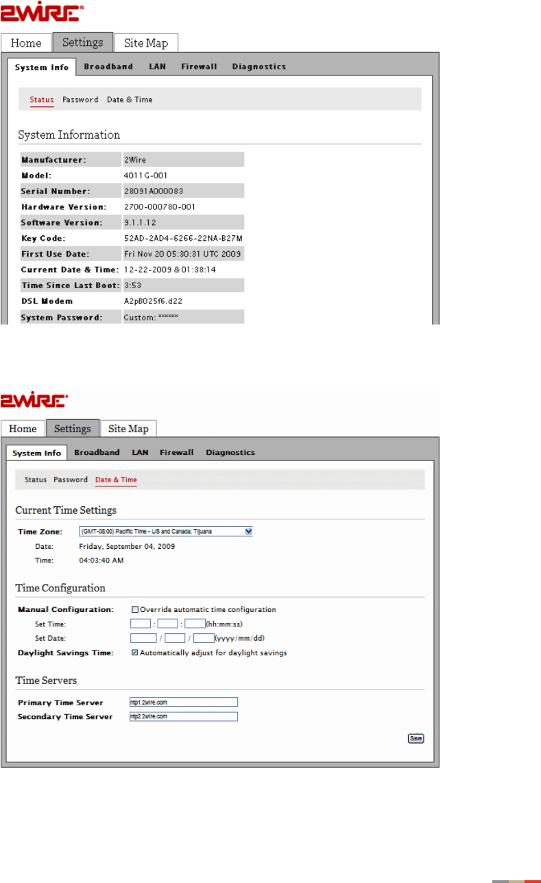
Configuring Date and Time
The 2Wire gateway sets the time automatically using time servers on the Internet. It retrieves date
and time information in Greenwich Mean Time (GMT). Your local time is set using the Time Zone
setting you configured when you set up your system.
To change your time zone settings:
1. Open a Web browser and enter http://home, http://gateway.2Wire.net, or
http://192.168.1.254 to access the gateway user interface; the Home page opens.
Configuring Date and Time 21
CHAPTER 3: Starting the User Interface
2. Click Settings; the Settings page opens displaying the system information.
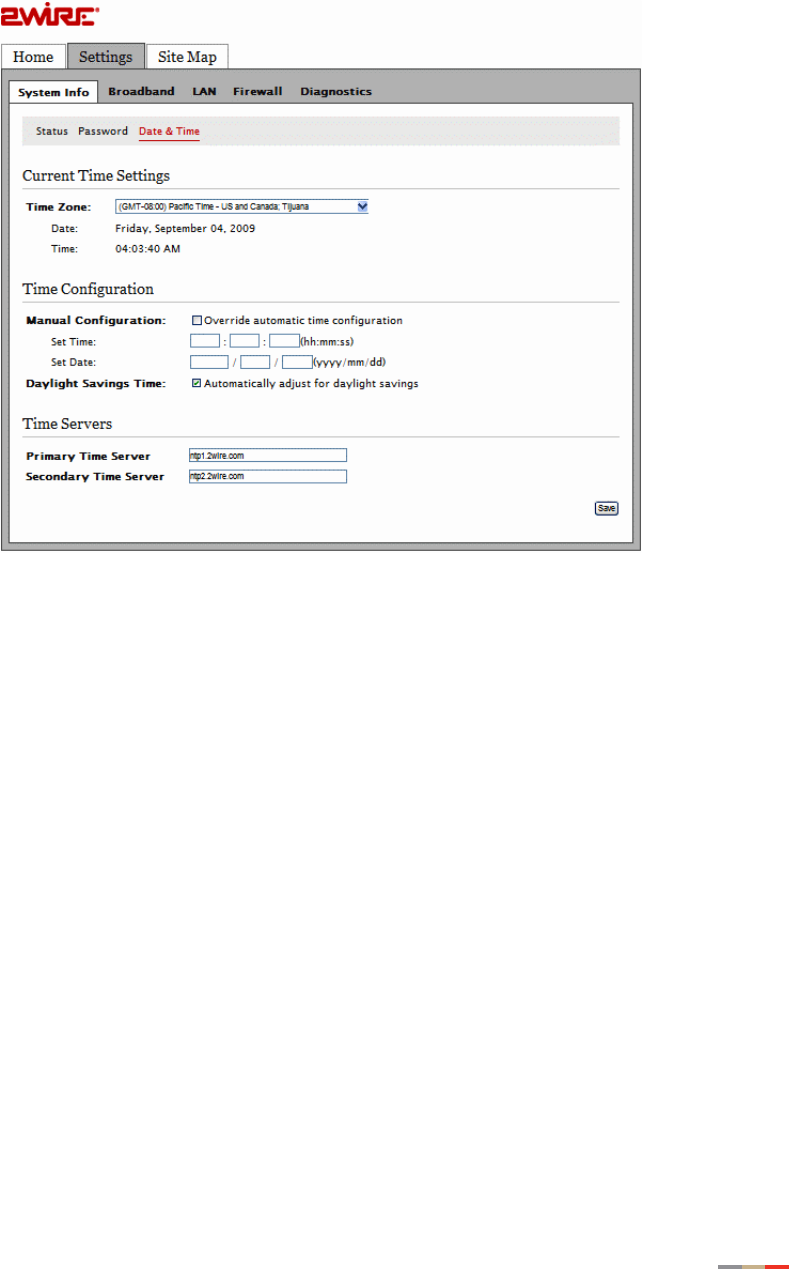
3. Click Date & Time; a page similar to the following opens.
4. Select the appropriate time zone from the Time Zone drop-down list.
5. Click Save.
CHAPTER 3: Starting the User Interface
22 Overriding Automatic Date and Time Configuration
Overriding Automatic Date and Time Configuration
Typically, the 2Wire Gateway sets the date and time automatically using time servers on the
Internet. You can override these settings and manually set them.
To manually change the date and time settings:
1. Open a Web browser and enter http://home, http://gateway.2Wire.net, or
http://192.168.1.254 to access the gateway user interface; the Home page opens.
2. Click Settings; the Settings page opens displaying the system information.
Overriding Automatic Date and Time Configuration 23
CHAPTER 3: Starting the User Interface
3. Click Date & Time; a page similar to the following opens.
4. Select Manual Configuration to override the automatic time configuration.
5. Enter the desired time and date information in the Set Time and Set Date fields.
6. Select Daylight Savings Time to enable the automatic daylight saving time adjustment, if
applicable.
7. Click Save.

CHAPTER 3: Starting the User Interface
24 Overriding Automatic Date and Time Configuration
This page is intentionally left blank.

25
CHAPTER 4
Configuring the Wireless Network
When the gateway is properly installed, the wireless network is functional. Your gateway is
preconfigured with settings that optimize Wi-Fi performance. It is recommended that you leave the
default settings in place.
If you are knowledgeable with the wireless technology and want to modify these settings, this
section provides instructions to perform the following advanced configurations:
•Setting up your Wireless Network on page 26
•Securing your Wireless Network on page 28
•Customize Private Wireless Settings on page 31
CHAPTER 4: Configuring the Wireless Network
26 Setting up your Wireless Network
Setting up your Wireless Network
If you are in a densely populated area, or if you regularly connect to more than one wireless
network (such as one at work and one at home), it is good practice to give your wireless network a
unique name, which makes it easy to identify when you select the wireless network to which to
connect. The default wireless network name is 2WIREXXX, where XXX represents the last three
digits of the serial number on the gateway (for example, 2WIRE954).
1. Open a Web browser and enter http://home, http://gateway.2Wire.net, or
http://192.168.1.254 to access the gateway user interface; the Home page opens.
Setting up your Wireless Network 27
CHAPTER 4: Configuring the Wireless Network
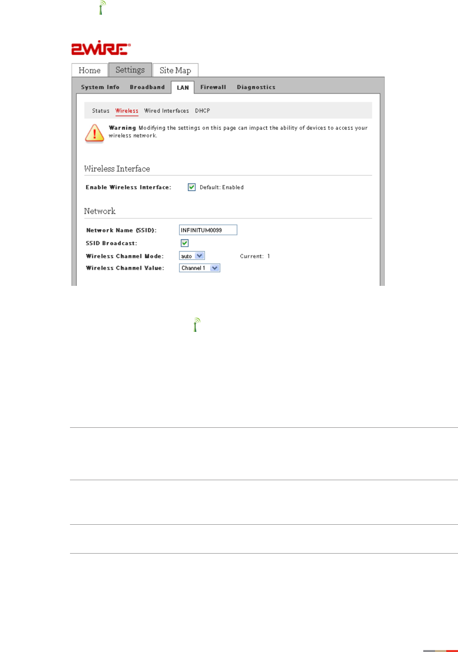
2. Click ; the Wireless Interface page opens.
3. Enter a name assigned to your wireless network in the Network Name (SSID) field.
This name appears next to on the Home page.
4. Enable or disable the broadcast of the SSID over the wireless network by selecting or
deselecting the check box.
•Enabled is the default setting, which means that your SSID is visible to anyone who is
scanning for a network to which to connect.
• Disabled secures your wireless network by not announcing its presence. Deselect the
Enable check box to disable it.
Note If you add a PC or device later, the wireless client will be unable to scan and
connect to your wireless network when the SSID broadcast is disabled. You will
need to manually add a wireless profile in the client device to connect to the
wireless network instead of selecting the SSID name from a typical scan list.
5. Select the channel mode (radio frequency band) that the access point (AP) uses for your
wireless network.
Note It is best to select Auto because a channel is automatically selected to minimize
interference.
6. Select a channel value from its drop-down list if you selected a channel mode other than
Auto in 5.
7. Click Save.
CHAPTER 4: Configuring the Wireless Network
28 Securing your Wireless Network
Securing your Wireless Network
In addition to using the encryption key to secure your wireless network, you can also use the MAC
address filtering feature to enhance the overall security solution provided by WPA/WEP.
Using the Encryption Key
It is good practice to customize an encryption key for wireless communication. When it is defined,
each wireless client needs to have that encryption key to connect to your wireless network.
1. Open a Web browser and enter http://home, http://gateway.2Wire.net, or
http://192.168.1.254 to access the gateway user interface.
2. Click on the Home page; the Wireless Interface page opens.
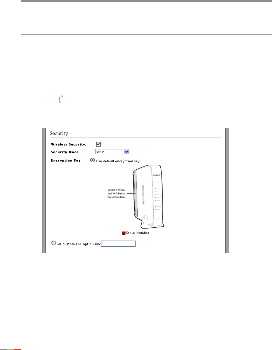
3. Scroll down to the Security pane.
mWireless security is enabled by default. Do not disable the security authentication
and security features; they protect your private data transmission over the wireless
link. Doing so may compromise the security of your PCs or other devices and lead
to theft of service or loss of bandwidth.

Securing your Wireless Network 29
CHAPTER 4: Configuring the Wireless Network
4. Select an authentication setting from the Security Mode drop-down list:
Note Check the capabilities of the wireless clients that will be accessing this network
and find the most secure protocol that is supported by all.
•wep. The Wireless Encryption Protocol (WEP) is an older security protocol that allows
any wireless clients within the radio range to access your network without an
encryption key. This setting provides the least level of security. For security reasons,
do not select this setting unless there is compatibility issue with an older wireless
client. For added protection, set an encryption key on your AP and enter the same key
into your other wireless clients.
•wpaPsk. This default setting provides good security and works with most wireless
clients but perhaps not on some older clients. This setting requires that an encryption
key to be set on the AP and that the wireless client be configured to use Wi-Fi
Protected Access – Pre-Shared Key (WPA-PSK) with the same encryption key.
•wpa2Psk. This setting requires that wireless clients use only WPA2-PSK to access
your networks. An encryption key must be configured on the AP and entered into the
wireless client. WPA2-PSK is currently the most secure Wi-Fi encryption protocol but
may not be available on many wireless clients.
•wpaPskMixed. This setting allows a wireless client to use either WPA-PSK or
WPA2-PSK to access your network. An encryption key must be configured on the AP
and the same key must be entered on the wireless client.
5. Select the radio button next to Use default encryption key field and use the WEP Key for
wireless authentication.
6. Select the radio button next to the Set custom encryption key field to manually configure
the encryption key. Enter your encryption key consisting a minimum of 8 characters.
Note This pass phrase is applicable only for the WpaPsk and Wpa2Psk security
modes.
7. Click Save.
Using the MAC Address Filtering
The MAC address is a factory-programmed address assigned to each hardware device. The MAC
address filtering feature enables you to block or allow wireless connection to all devices or an
individual device. It is most often used to allow only “known and trusted” devices to associate to
the AP. By default, the MAC address filtering is disabled, meaning that all discovered devices are
allowed. When enabled, the wireless connection is only available to the devices having their MAC
addresses added to the allowed list.
Note Security is not optimized if you use only MAC address filtering option. It should be used in
combination with the wireless security protocols to enhance the overall security solution.
To enable the MAC filter to block all devices:
1. Open a Web browser and enter http://home, http://gateway.2Wire.net, or
http://192.168.1.254 to access the gateway user interface.
2. Click on the Home page; the Wireless Interface page opens.
CHAPTER 4: Configuring the Wireless Network
30 Securing your Wireless Network
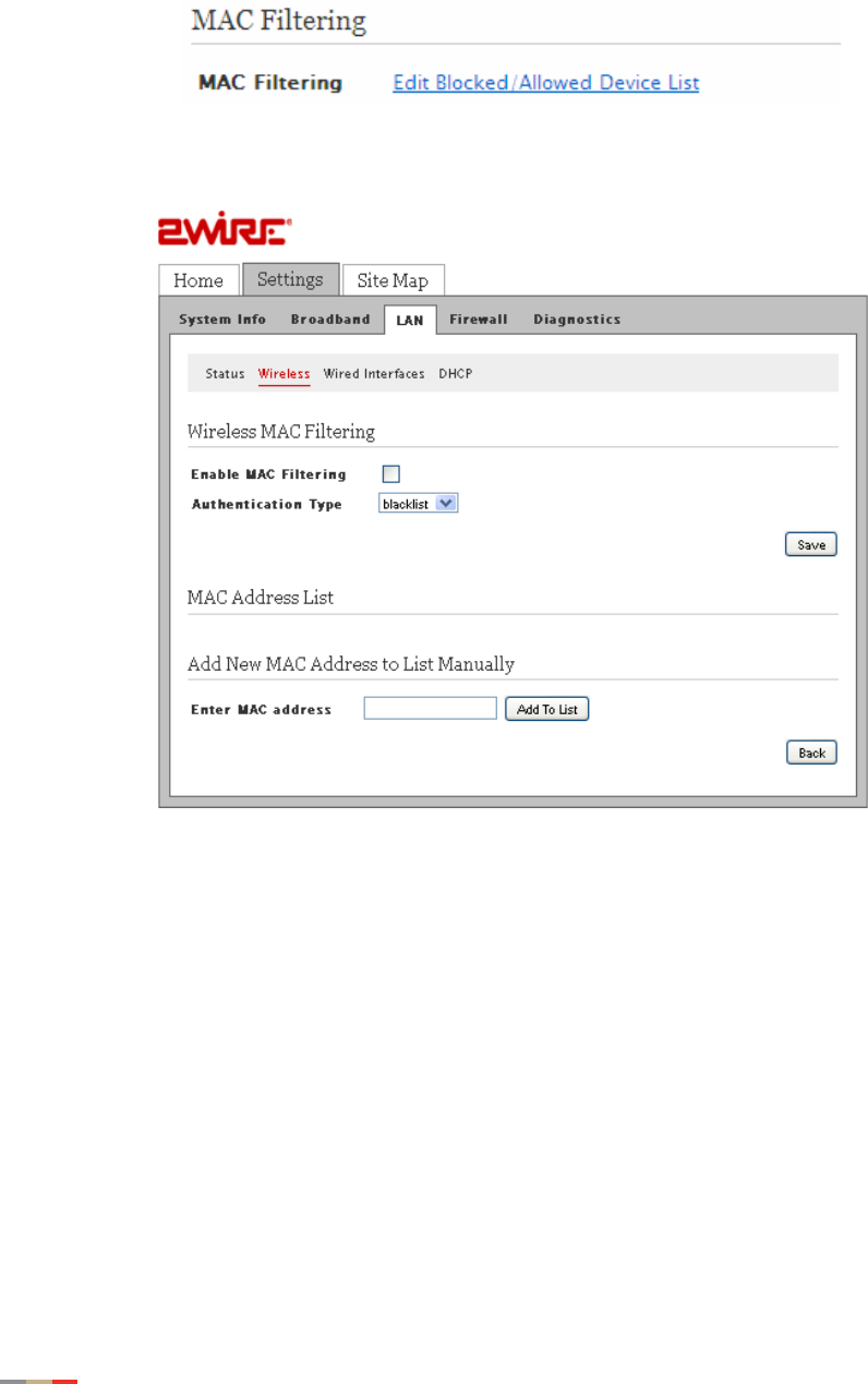
3. Scroll down to the MAC Filtering pane.
4. Click Edit Blocked/Allowed Device List; the Wireless MAC Filtering page opens.
5. Enter the MAC address you want to block in the Enter MAC address field.
6. Click Add to List.
7. Select the Enable check box to block all devices.
8. Select the Authentication Type: blacklist (default), whitelist.
•blacklist is the default setting that blocks all devices.
•whitelist is a setting that allows access to all devices.
9. Click Save; a dialog box opens confirming that the configuration is changed.

Customize Private Wireless Settings 31
CHAPTER 4: Configuring the Wireless Network
Customize Private Wireless Settings
The Advanced Settings pane allows you to customize wireless settings. It is recommended that
you leave the default settings in place; however, if you are experiencing connection or
performance difficulties, altering these settings may improve performance.
1. Open a Web browser and enter http://home, http://gateway.2Wire.net, or
http://192.168.1.254 to access the gateway user interface.
2. Click on the Home page; the Wireless Interface page opens.
3. Scroll down to the Advanced Settings pane.
1. Select a power setting from its associated drop-down list.
2. Select a wireless mode from its associated drop-down list.
3. Enter a value in the range from 1 to 3 seconds in the DTIM Period field. (The default is 1.)
This Delivery Traffic Indication Message (DTIM) value determines the interval at which the
access point sends its broadcast traffic.
4. Select the maximum rate at which your wireless connection works: auto or 6, 9, 18, 24, 36,
48, and 54 Mbps.
5. Click Save.

CHAPTER 4: Configuring the Wireless Network
32 Customize Private Wireless Settings
This page is intentionally left blank.
33
CHAPTER 5
Configuring Firewall
Settings
The gateway includes default firewall settings that block unwanted access from the Internet; it is
recommended that you leave the default settings in place. If necessary, you can allow Internet
traffic or users through the firewall to your LAN devices, applications, and servers. This section
provides instructions to:
•Hosting Applications on page 33
•Removing Hosted Applications on page 35
•Defining New Application Profiles on page 37
•Deleting Application Profiles on page 41
Hosting Applications
To allow access from the Internet to applications running on computers inside your home network,
you need to open firewall pinholes and associate the intended application(s) with a computer
connected with your gateway. If you cannot find a listing for your application, you can define an
application profile that includes the protocol and port information (refer to Defining New Application
Profiles on page 37).
To host applications:
1. Open a Web browser and enter http://home, http://gateway.2Wire.net, or
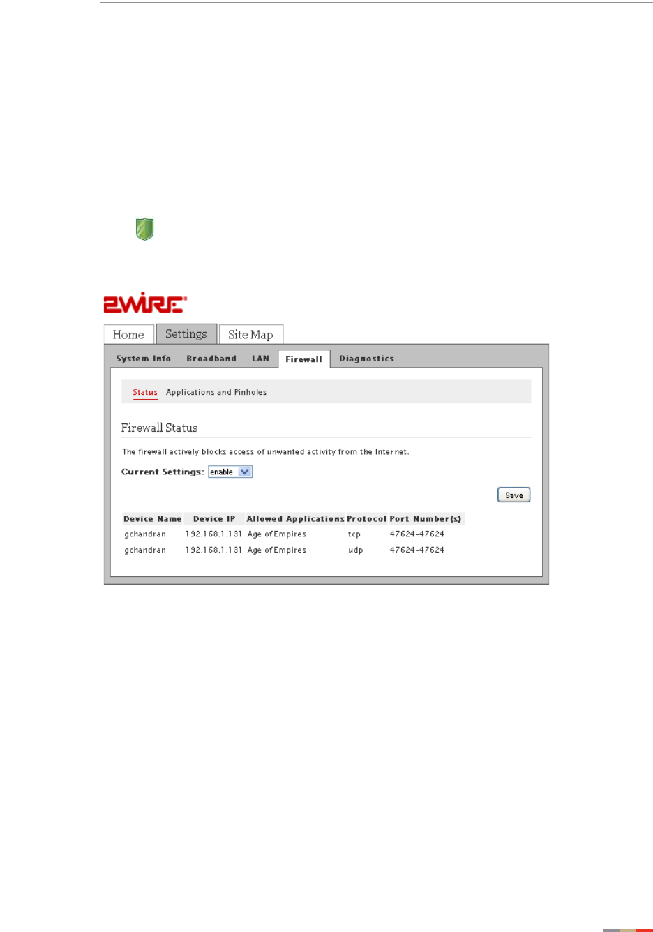
http://192.168.1.254 to access the gateway user interface.
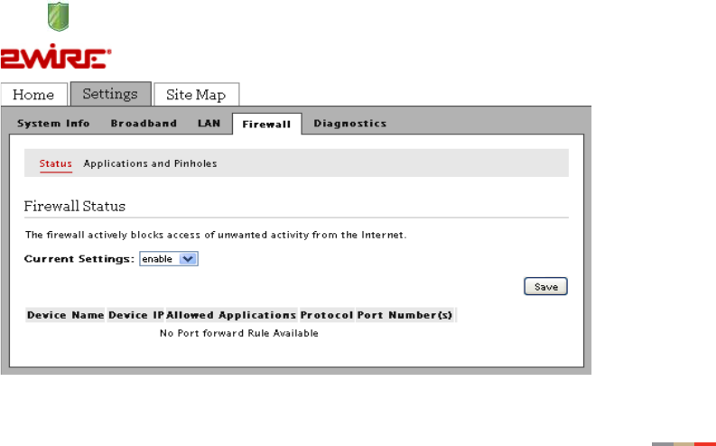
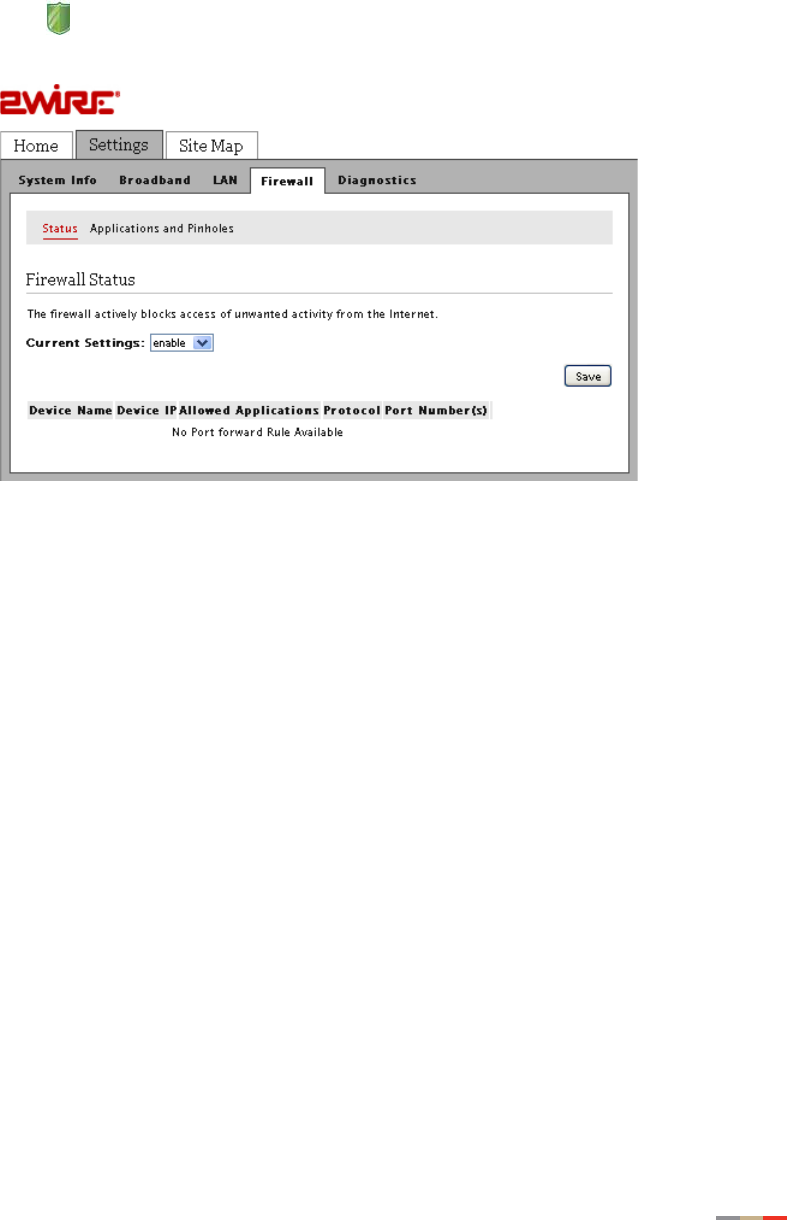
2. Click on the Home page; the Firewall Status page opens.
CHAPTER 5: Configuring Firewall Settings
34 Hosting Applications
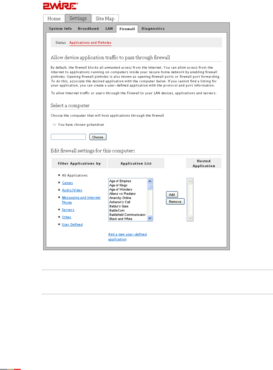
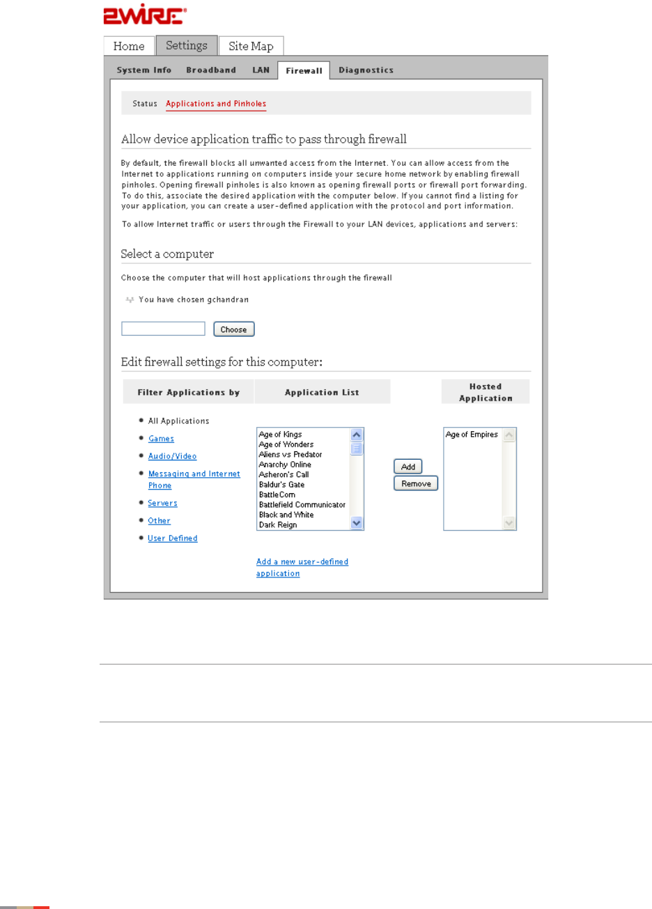
3. Select Applications and Pinholes; a page similar to the following opens.
4. Select the computer that you want to host the application(s).
Note If the computer you want to select is unlisted because it is powered off, you still
can select it as long as it is on the same network and you know its IP address.
Enter the intended IP address, then click Choose.
5. Filter the application list by selecting the category; your selection is displayed in the
Application List panel.
6. Select from the Application List panel the application(s) you want to host.
Removing Hosted Applications 35
CHAPTER 5: Configuring Firewall Settings
Note To select multiple applications, hold down the [Shift] or [Ctrl] keys while making
your selections. Using the [Shift] key lets you make your selections in a
contiguous order while the [Ctrl] key selects the groups in a random order.
7. Click Add; the application(s) you selected appears in the Hosted Applications panel.
Removing Hosted Applications
1. Open a Web browser and enter http://home, http://gateway.2Wire.net, or
http://192.168.1.254 to access the gateway user interface.
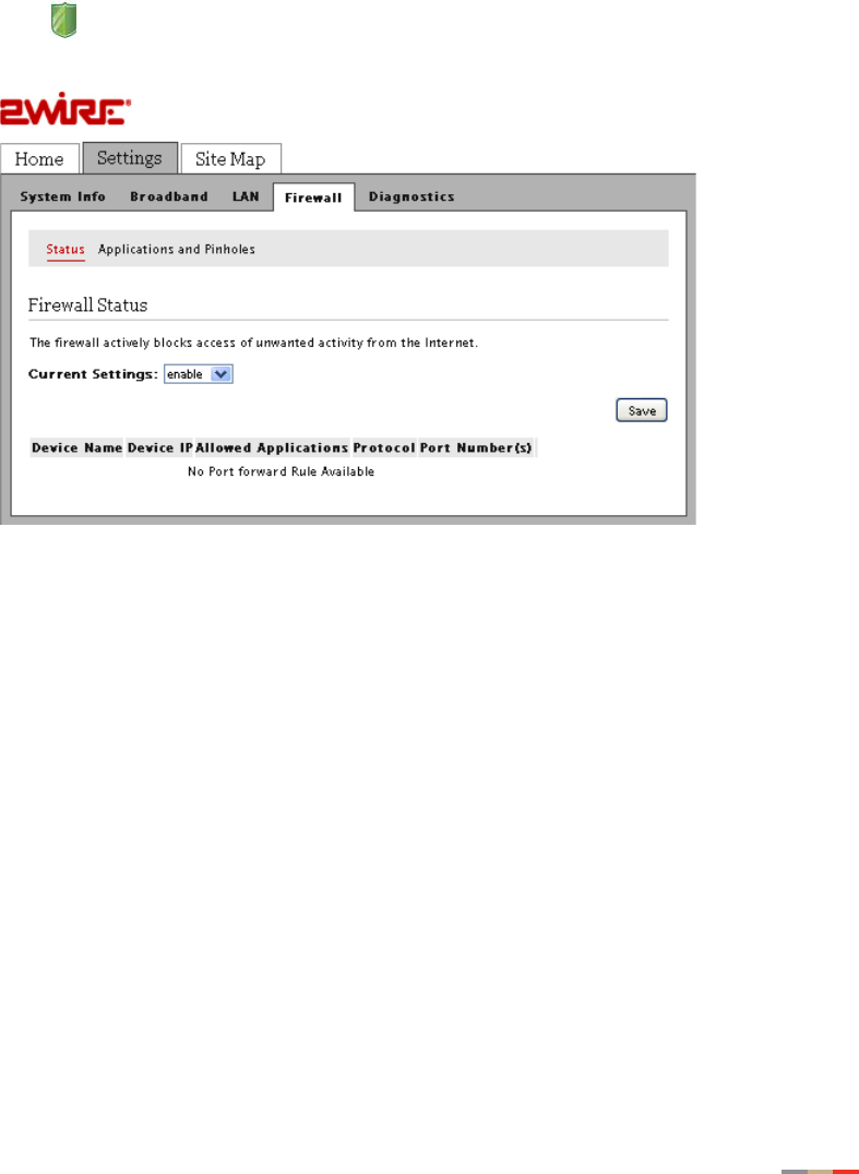
2. Click on the Home page; the Firewall Status page opens, displaying the current hosted
application settings.
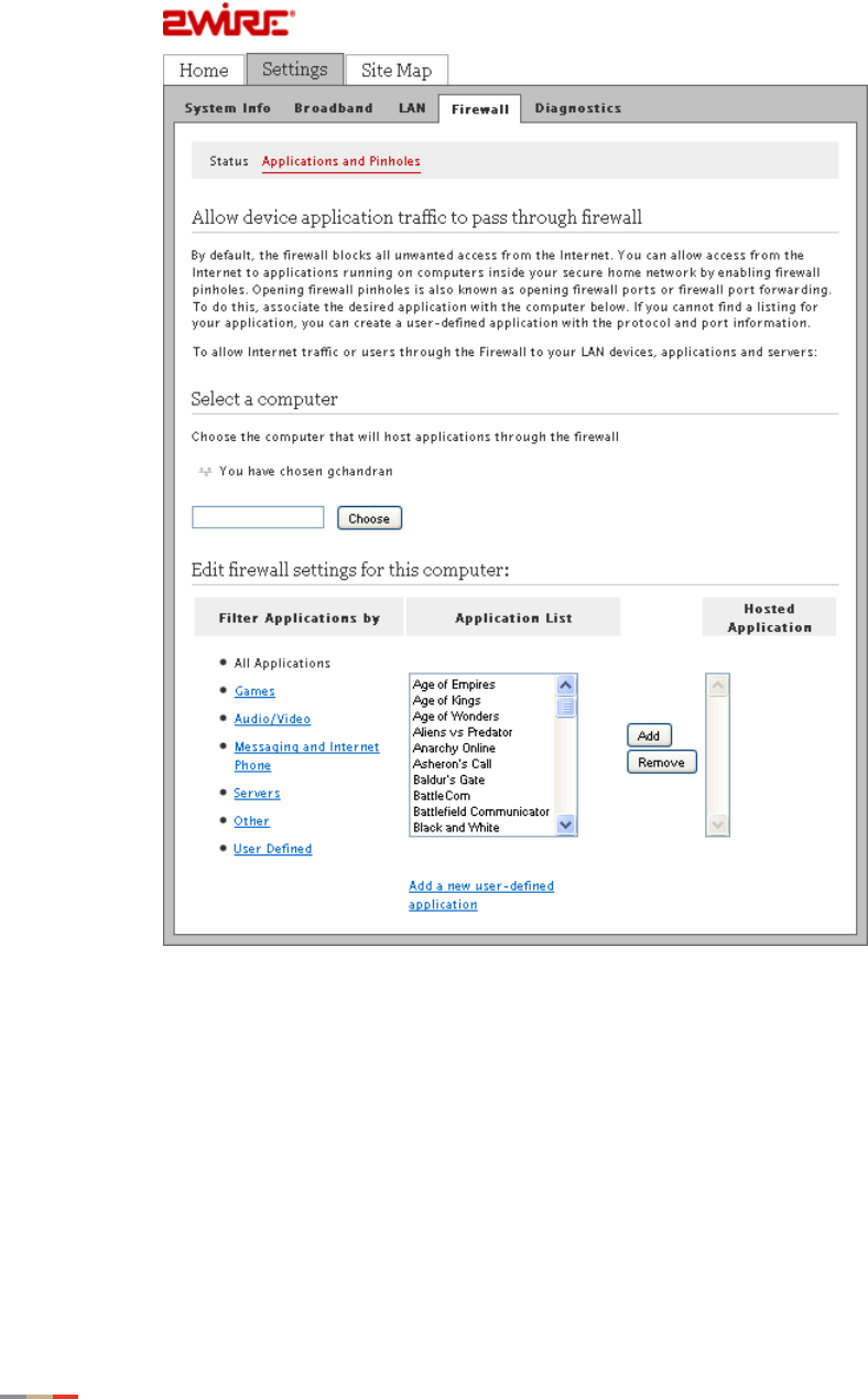
3. Select Applications and Pinholes; a page opens showing the current hosted applications.
CHAPTER 5: Configuring Firewall Settings
36 Removing Hosted Applications
4. Select the application(s) you want to remove from the Hosted Applications panel, click
Remove.
Note To select multiple applications, hold down the [Shift] or [Ctrl] keys while making
your selections. Using the [Shift] key lets you make your selections in a
contiguous order while the [Ctrl] key selects the groups in a random order.
5. Click Save; a message appears informing you of the status. The application(s) you
selected is removed from the Hosted Applications panel and returned to the Application
List panel.
Defining New Application Profiles 37
CHAPTER 5: Configuring Firewall Settings
Defining New Application Profiles
An application profile includes protocol and port information that allow your system’s firewall to
pass through application-specific data. You can define an application profile that is not included in
the Application List. This feature is typically used if the application for which you would like to pass
through data to a given computer is new or has been recently updated to a new version.
To define a new application profile:
1. Open a Web browser and enter http://home, http://gateway.2Wire.net, or
http://192.168.1.254 to access the gateway user interface.
2. Click on the Home page; the Firewall Status page opens.
CHAPTER 5: Configuring Firewall Settings
38 Defining New Application Profiles
3. Select Applications and Pinholes; a page similar to the following opens.
Defining New Application Profiles 39
CHAPTER 5: Configuring Firewall Settings
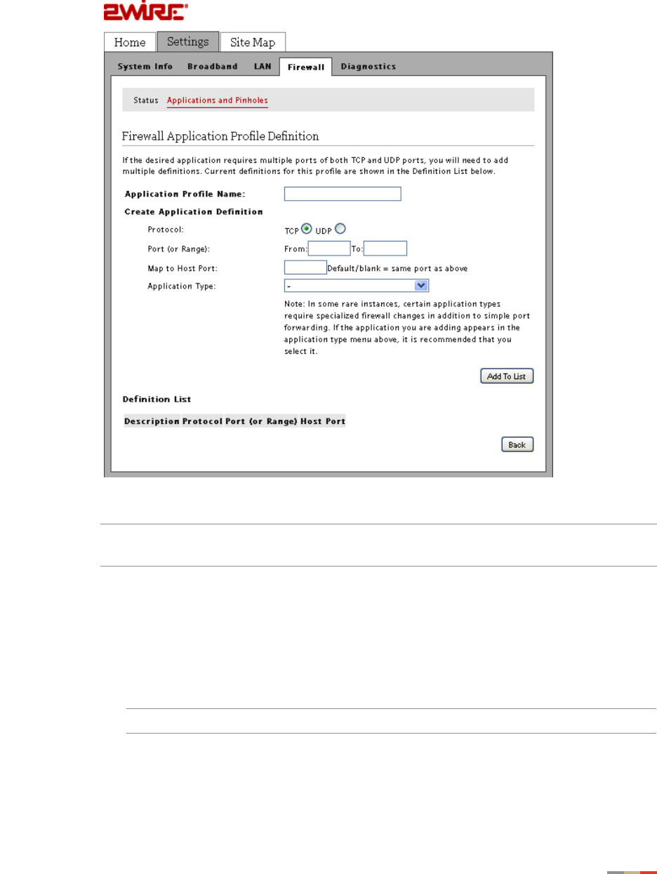
4. Click Add a new user-defined application; the Firewall Application Profile Definition page
opens.
5. Enter the application profile name in the Application Profile Name field.
Note For easy identification, use the name of the application (for example, Redwing
Game Server).
6. Create a definition for your application that is to be allowed through the firewall.
• In the Protocol field, select the TCP or UDP radio button. If the application you are
adding requires both, you need to create a separate definition for each.
• In the Port (or Range) field, enter the port or port range the application uses. For
example, some applications require only one port to be opened (such as TCP port
500); others require that all TCP ports from 600 to 1000 be opened.
Note If only one port is required, enter the port number in the From field.
• In the Map to Host Port field, enter a value that maps the port range you established
in the Port field to the local computer. For example, if you set the value to 4000 and
the port range being opened is 100 to 108, the forwarded data to the first value in the

CHAPTER 5: Configuring Firewall Settings
40 Defining New Application Profiles
range will be sent to 4000. Subsequent ports will be mapped accordingly; 101 will be
sent to 4001, 102 will be sent to 4002, and so forth.
• From the Application Type drop-down list, select the application type. If you do not
know the application type, select nothing.
Note You can find the above information in the documentation provided by the
company that produces the application.
7. Click Add To List; a Configuration Successful message appears on the following page
indicating that the profile is created.
Deleting Application Profiles 41
CHAPTER 5: Configuring Firewall Settings
Deleting Application Profiles
1. Open a Web browser and enter http://home, http://gateway.2Wire.net, or
http://192.168.1.254 to access the gateway user interface.
2. Click on the Home page; the Firewall Status page opens.

CHAPTER 5: Configuring Firewall Settings
42 Deleting Application Profiles
3. Select Applications and Pinholes; a page similar to the following opens.
Deleting Application Profiles 43
CHAPTER 5: Configuring Firewall Settings
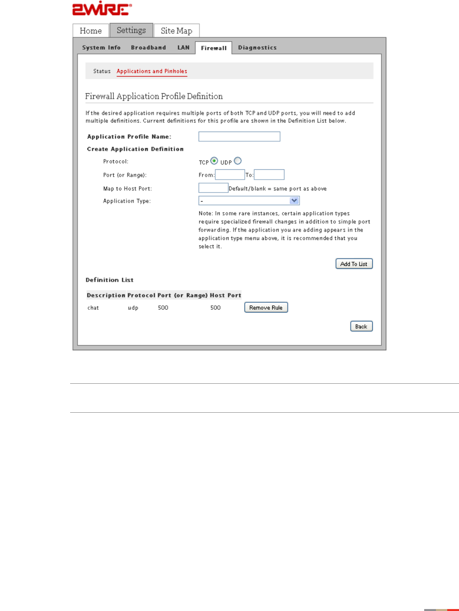
4. Click Add a new user-defined application; the Firewall Application Profile Definition page
opens.
5. Select the profile you want to delete, click Remove Rule.
Note Be sure to select the intended application. Once you click Remove Rule, the
profile is deleted.

CHAPTER 5: Configuring Firewall Settings
44 Deleting Application Profiles
This page is intentionally left blank.

45
CHAPTER 6
Configuring LAN Devices
Typically, your Internet service provider automatically assigns and configures a dynamic IP
address when your system connects to the Internet. Business or power users may use a static
address enabling them to run advanced services such as Internet servers and video conferences.
The availability of static IP addresses is usually an additional service offered by service providers.
In addition, changes from the default behavior of the gateway for private IP addressing may also
be used by some users.
Note Configure these settings only if you are familiar with computer networking technologies.
This section provides instructions to:
•Adding New Static Routes on page 46
•Configuring DHCP on page 47
•Allocating an Address Pool for All Devices on page 52
•Disabling Ethernet Interfaces on page 56
CHAPTER 6: Configuring LAN Devices
46 Adding New Static Routes
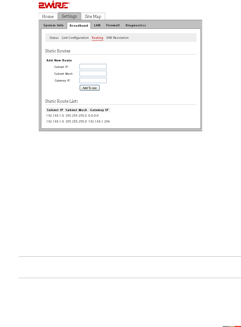
Adding New Static Routes
You can create a local network that has broadband network-accessible IP addresses by creating a
route from the Internet to the specified public network. This feature is typically used in conjunction
with broadband service that provides a range of available IP addresses.
Note Add the static routes first if you want to use the public address with your DHCP
configuration.
1. Open a Web browser and enter http://home, http://gateway.2Wire.net, or
http://192.168.1.254 to access the gateway user interface.
2. Click on the Home page; the Broadband Status page opens.
Configuring DHCP 47
CHAPTER 6: Configuring LAN Devices
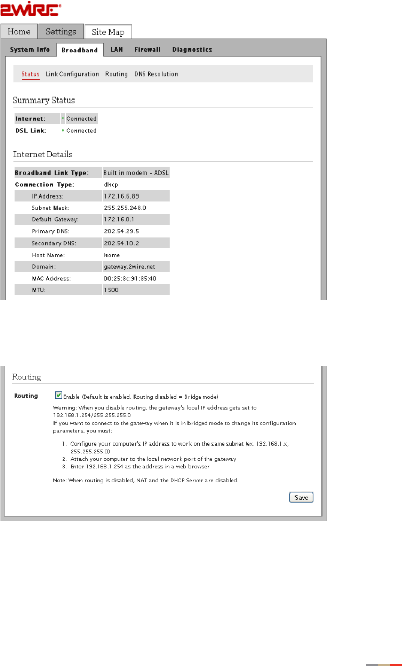
3. Click Routing; the following page opens.
4. Enter information in the following fields:
• In the Subnet IP field, enter the router address (this is the router address from the
secondary subnet provided by the service provider).
• In the Subnet Mask field, enter the subnet mask (this is the router mask from the
secondary subnet provided by the service provider).
• In the Gateway IP field, enter the IP address of the router for the specified subnet.
5. Click Add to List.
Configuring DHCP
Dynamic Host Configuration Protocol (DHCP) allows for dynamic allocation of network addresses
and configuration to newly attached hosts. The gateway can be both a DHCP client and DHCP
server. The gateway acts as a client when it communicates to your service provider over the
Internet using DHCP. For this communication, you cannot modify the related DHCP settings. The
gateway is a DHCP server to your local network devices such as the computers connecting to it.
Note If you change the local network IP address range, you must renew the DHCP lease on all
devices on the gateway’s local network and manually reconfigure all devices configured
with static IP addresses.
CHAPTER 6: Configuring LAN Devices
48 Configuring DHCP
To configure the default DHCP information used as a local server:
1. Open a Web browser and enter http://home, http://gateway.2Wire.net, or
http://192.168.1.254 in the address line; the Home page opens.
2. Click Settings; the System Information page opens.

Configuring DHCP 49
CHAPTER 6: Configuring LAN Devices
3. Click LAN; a page similar to the following opens, displaying the private network
information and LAN devices connected to your network.
CHAPTER 6: Configuring LAN Devices
50 Configuring DHCP
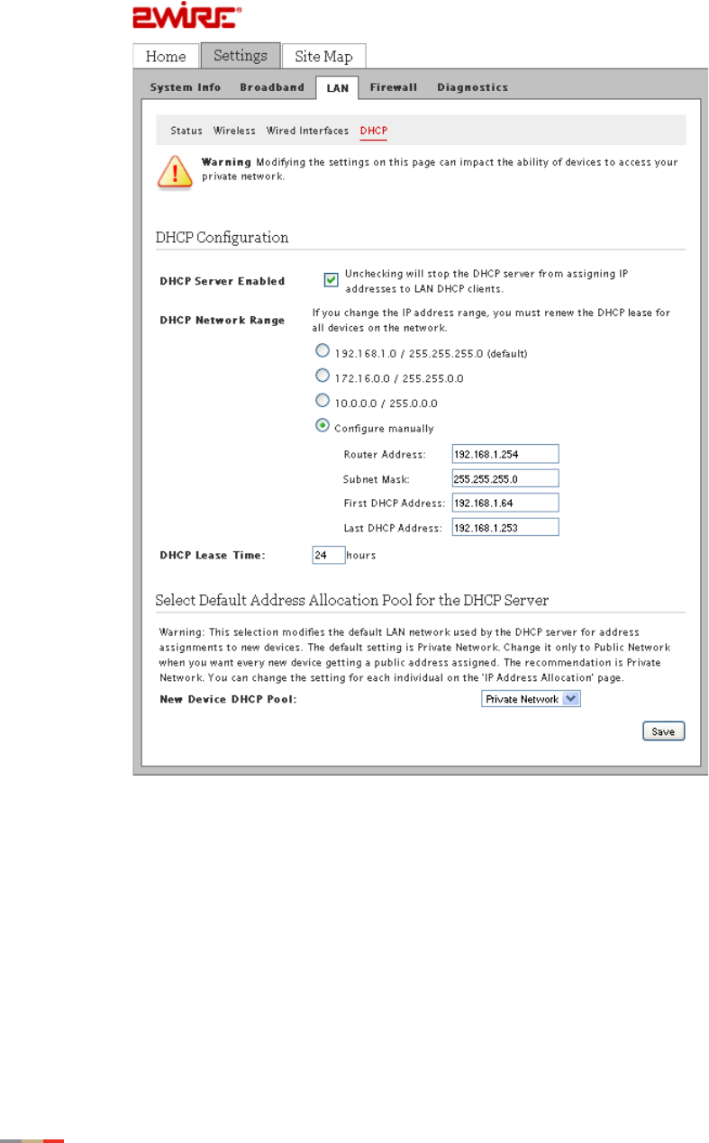
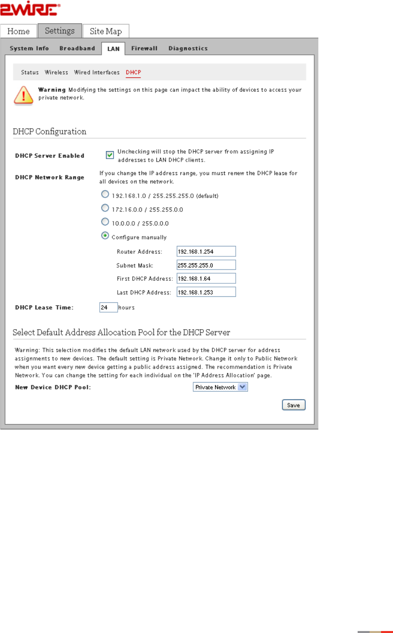
4. Click DHCP; the DHCP Configuration page opens.
5. Select Configure manually if you want to set up a range for the DHCP address IP pool.
6. Enter information in the following fields:
• In the Router Address field, enter the IP address of your gateway used for all
communication on your local devices.
• In the Subnet Mask field, enter the subnet mask used for all communication on your
local devices (the default is 255.255.255.0).
• In the First DHCP Address field, enter the first IP address in the DHCP address pool
that you will be distributing over the private network.
•In the Last DHCP Address field, enter the last IP address in the DHCP address pool
that you will be distributing over the private network.

Configuring DHCP 51
CHAPTER 6: Configuring LAN Devices
7. Enter a numerical value in the DHCP Lease Time field that represents the number of
hours you can use the assigned IP address before the DHCP lease expires. Select a
public IP address pool that is assigned via DHCP on the local area network.
8. Select Private Network from the New Device DHCP Pool drop-down list.
9. Click Save.
CHAPTER 6: Configuring LAN Devices
52 Allocating an Address Pool for All Devices
Allocating an Address Pool for All Devices
The default DHCP server address allocation pool is set to Private Network. You can change it to
Public Network when you want all devices to have the same addresses assigned. To change the
address setting for individual devices, refer to Allocating an Address Pool for All Devices on
page 52.
To change the default address allocation pool:
1. Open a Web browser and enter http://home, http://gateway.2Wire.net, or
http://192.168.1.254 in the address line; the Home page opens.

Allocating an Address Pool for All Devices 53
CHAPTER 6: Configuring LAN Devices
2. Click Settings; the System Information page opens.

CHAPTER 6: Configuring LAN Devices
54 Allocating an Address Pool for All Devices
3. Click LAN; a page similar to the following opens, displaying the private network
information and LAN devices connected to your network.
Allocating an Address Pool for All Devices 55
CHAPTER 6: Configuring LAN Devices
4. Click DHCP; the DHCP Configuration page opens.
5. Select Private Network from the New Device DHCP Pool drop-down list.
6. Click Save.
CHAPTER 6: Configuring LAN Devices
56 Disabling Ethernet Interfaces
Disabling Ethernet Interfaces
Disabling Ethernet networking enhances security. When Ethernet networking is enabled, users
can connect through Ethernet port without going through any authentication. If Ethernet port is
disabled and default wireless settings are changed, then the user has to obtain the correct
wireless authentication parameters from the local administrator. Thus, disabling Ethernet
networking enhances physical security and is more suited for business environment such as
kiosks, schools, and so on.
By default, the gateway is shipped with the Ethernet interface enabled. When disabled, you will be
unable to access the Internet using the Ethernet port connection. Before you disable the Ethernet
ports, make sure that the wireless connection is set up and working properly.
1. Open a Web browser and enter http://home, http://gateway.2Wire.net, or
http://192.168.1.254 in the address line; the Home page opens.
Disabling Ethernet Interfaces 57
CHAPTER 6: Configuring LAN Devices
2. Click Settings; the System Information page opens.
CHAPTER 6: Configuring LAN Devices
58 Disabling Ethernet Interfaces
3. Click LAN; a page similar to the following opens, displaying the private network
information and LAN devices connected to your network.

Disabling Ethernet Interfaces 59
CHAPTER 6: Configuring LAN Devices
4. Click Wired Interfaces; a page similar to the following opens.
5. Deselect Enable to disable the Ethernet connection.
6. Click Save.

CHAPTER 6: Configuring LAN Devices
60 Disabling Ethernet Interfaces
This page is intentionally left blank.

61
CHAPTER 7
Configuring the
Broadband Connection
Typically your Broadband and Internet connection settings are automatically provided by your
service provider. When the gateway is properly connected it automatically detects which DSL line
to use; it does not require further configuration.
If the information was not automatically provided and you need to manually configure your
Broadband and Internet connection settings, make sure to have the following ATM information and
authentication settings from your service provider:
• Circuit identifier (VPI/VCI)
• Encapsulation method
• PPP username
• PPP password
CHAPTER 7: Configuring the Broadband Connection
62 Configuring DSL and ATM Settings
Configuring DSL and ATM Settings
All information you need to configure this setting is provided by your service provider.
1. Open a Web browser and enter http://home, http://gateway.2Wire.net, or
http://192.168.1.254 to access the gateway user interface.
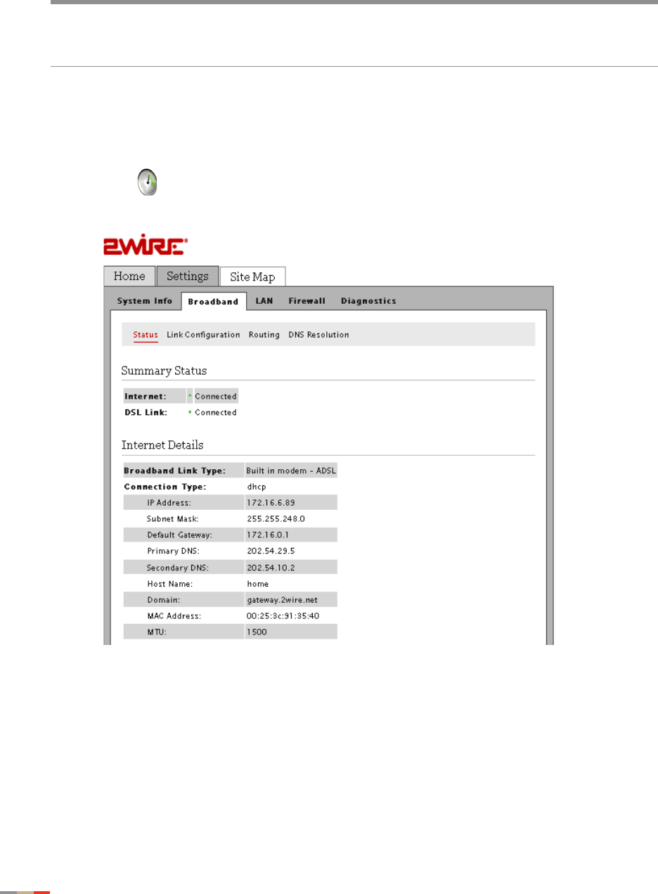
2. Click on the Home page; the Summary Status page opens.
cModifying the gateway broadband configuration settings may impede or interrupt
your broadband service. Modify these settings only if you are familiar with
networking technology.
Configuring DSL and ATM Settings 63
CHAPTER 7: Configuring the Broadband Connection
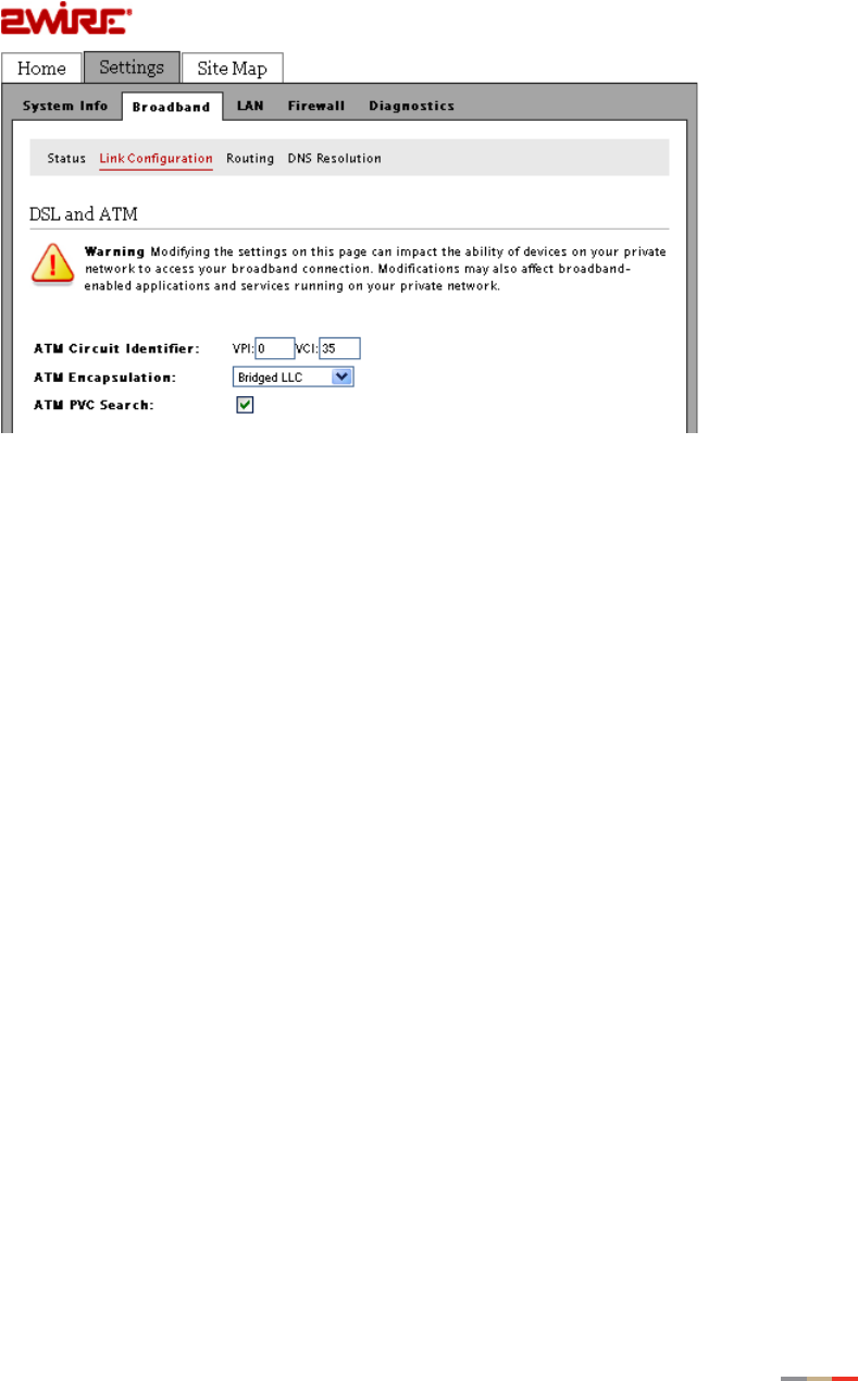
3. Click Link Configuration; a page similar to the following opens.
4. Enter the VPI and VCI you want the gateway to use in connecting to the ISP.
5. Select the encapsulation method from the ATM Encapsulation drop-down list.
• For PPPoE or Bridging, select Bridged LLC or Bridged VC-Mux.
• For PPPoA, select Routed LLC or Routed VC-Mux.
6. Select the ATM/PVC Search check box to enable the PVC search. PVC search enables
the device to automatically detect ISP's VPI/VCI values so that the end user need not
enter VPI/VCI values.
7. Click Save.
CHAPTER 7: Configuring the Broadband Connection
64 Configuring the Connection Type
Configuring the Connection Type
The connection type identifies the method by which the gateway connects to the ISP.
1. Open a Web browser and enter http://home, http://gateway.2Wire.net, or
http://192.168.1.254 to access the gateway user interface.
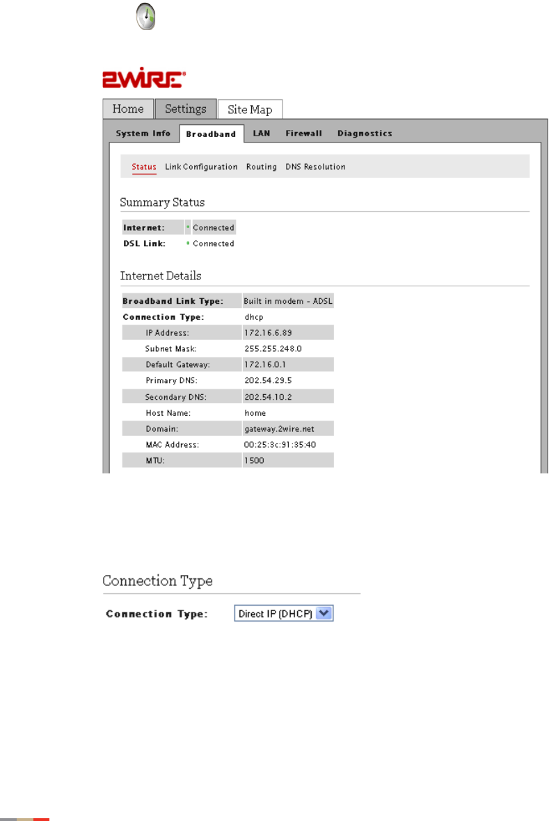
2. Click on the Home page; the Summary Status page opens.
3. Click Link Configuration; the Link Configuration page opens.
4. Scroll down to the Connection Type pane.
5. Select the connection type from its corresponding drop-down list.
• If you selected the Direct IP, continue with the next step.
• If you selected the PPPoE or PPPoA, continue with the Configuring PPP
Authentication and Settings section to set up your username and password.
6. Select the Enable check box for Auto Wan Address Mode field to automatically select
the WAN interfaces (ADSL/ADSL2/ADSL2+).
Configuring PPP Authentication and Settings 65
CHAPTER 7: Configuring the Broadband Connection
7. Click Save.
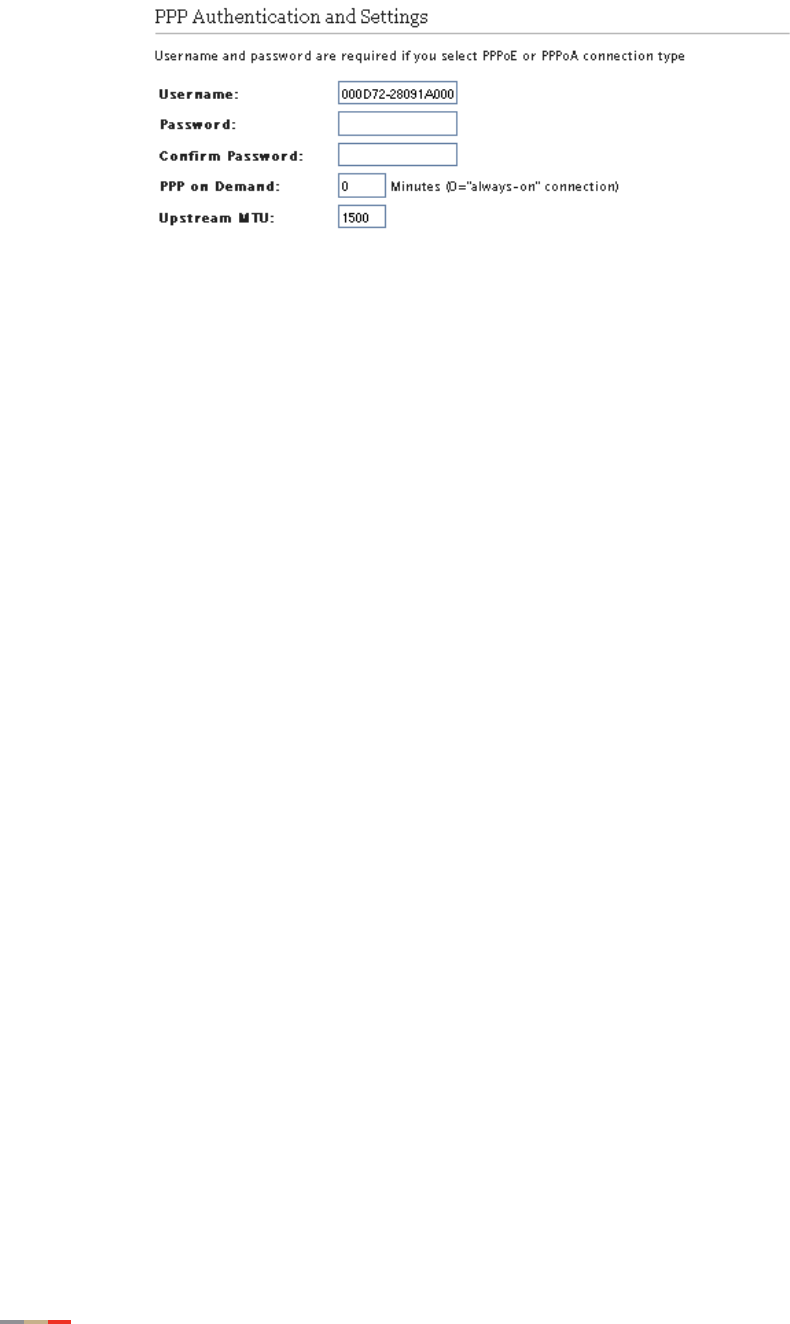
Configuring PPP Authentication and Settings
The PPPoE or PPPoA connection type requires authentication to be connected.
To configure the PPP authentication settings:
1. Open a Web browser and enter http://home, http://gateway.2Wire.net, or
http://192.168.1.254 to access the gateway user interface.
2. Click on the Home page; the Summary Status page opens.
3. Click Link Configuration; the Link Configuration page opens.
4. Scroll down to the PPP Authentication and Settings pane.
CHAPTER 7: Configuring the Broadband Connection
66 Configuring PPP Authentication and Settings

Modifying Broadband IP Addresses 67
CHAPTER 7: Configuring the Broadband Connection
5. Enter your user name in the Username field (this is given to you by your service provider).
6. Enter your password in the Password field (this is given to you by your service provider).
7. Re-enter your password in the Confirm Password field.
8. Enter a value for the length of time you want the PPP session to remain active in the PPP
on Demand field.
• Setting the value to 0 indicates that the PPP session will remain on all the time.
• Setting the value between 1 to 10080 minutes, the PPP session will time-out
accordingly if the gateway does not detect outbound traffic destined for the Internet in
the specified time.
9. Click Save.
Modifying Broadband IP Addresses
By default, the gateway automatically obtains its broadband IP and DNS addresses from your
service provider. If you purchased a static IP from your service provider, you need to change the
broadband IP to the static IP assigned to you from your service provider.
To manually modify the broadband IP:
1. Open a Web browser and enter http://home, http://gateway.2Wire.net, or
http://192.168.1.254 to access the gateway user interface.
2. Click on the Home page; the Summary Status page opens.
CHAPTER 7: Configuring the Broadband Connection
68 Modifying Broadband IP Addresses
Modifying Broadband IP Addresses 69
CHAPTER 7: Configuring the Broadband Connection
3. Click Link Configuration; the Link Configuration page opens.
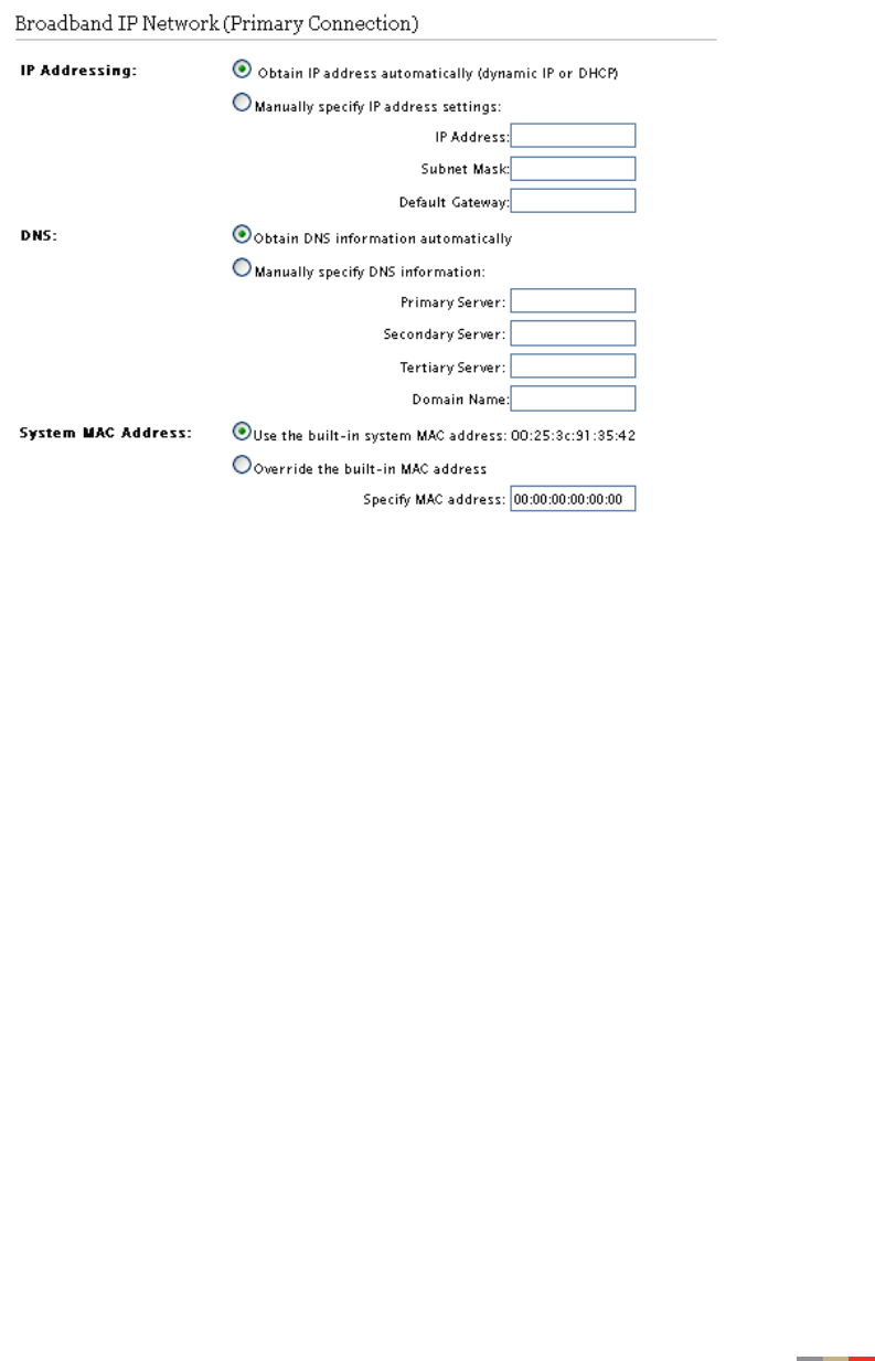
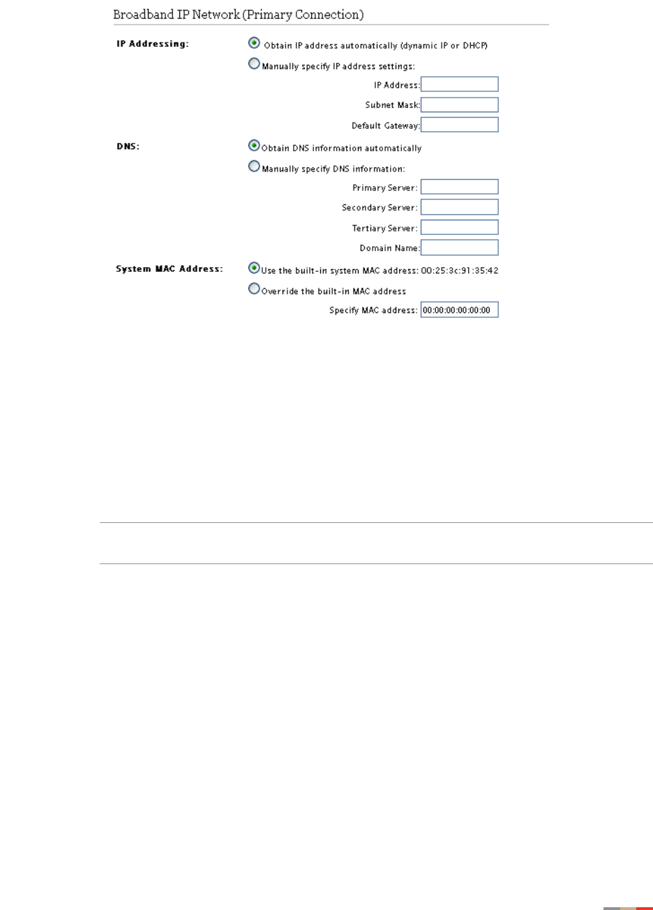
4. Scroll down to the Broadband IP Network pane.
5. Click the Manually specify IP address settings radio button.
6. Enter the following information:
• In the IP Address field, enter the IP address you want the gateway to use.
• In the Subnet Mask field, enter the subnet mask you want the gateway to use.
• In the Default Gateway field, enter the default gateway address you want the
gateway to use.
7. Click Save.
CHAPTER 7: Configuring the Broadband Connection
70 Specifying DNS Information Manually
Specifying DNS Information Manually
By default, the gateway automatically obtains its DNS server addresses from your service
provider.
1. Open a Web browser and enter http://home, http://gateway.2Wire.net, or
http://192.168.1.254 to access the gateway user interface.
2. Click on the Home page; the Summary Status page opens.
3. Click Link Configuration; the Link Configuration page opens.
4. Scroll down to the Broadband IP Network pane.
Specifying DNS Information Manually 71
CHAPTER 7: Configuring the Broadband Connection
5. Click the Manually specify your DNS information radio button.
6. Enter the following information:
• In the Primary Server field, enter the IP address of the primary DNS server that the
gateway is to use for DNS name resolution.
•In the Secondary Server field, enter the IP address of the secondary DNS server that
the gateway is to use for DNS name resolution.
• In the Domain Name field, enter the specific domain name to be used by the gateway.
7. Click Save.
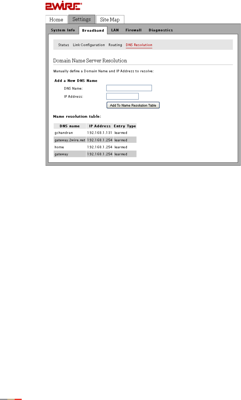
Note Skip the following steps if you do not want to manually add the new DNS
information to the resolution table at this time.
8. Add the new DNS information by clicking the DNS Resolution tab on the Link
Configuration page; the Domain Name Server Resolution page opens.
Overriding the System MAC Address 73
CHAPTER 7: Configuring the Broadband Connection
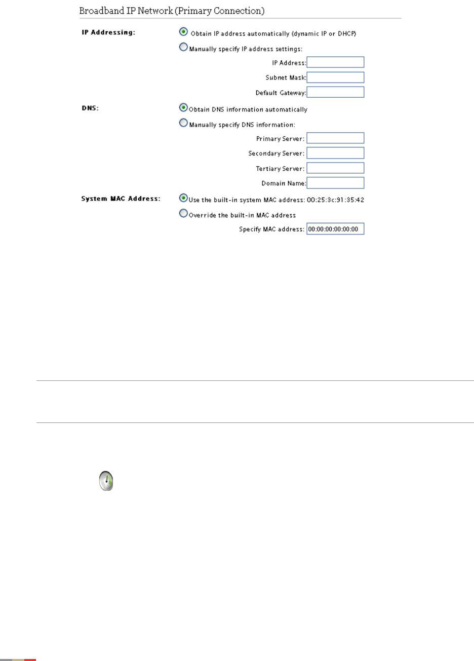
Overriding the System MAC Address
By default, the gateway uses its built-in hardware address for identification. You can override the
default MAC address If you are using devices that require a different MAC address.
1. Open a Web browser and enter http://home, http://gateway.2Wire.net, or
http://192.168.1.254 to access the gateway user interface.
2. Click on the Home page; the Summary Status page opens.
3. Click Link Configuration; the Link Configuration page opens.
4. Scroll down to the Broadband IP Network pane.
CHAPTER 7: Configuring the Broadband Connection
74 Changing to the Bridging Mode
5. Select the Override the built-in MAC address button.
6. Enter the MAC address in the corresponding field.
7. Click Save.
Changing to the Bridging Mode
By default, the 2Wire Gateway is configured in the routing mode.
Note When routing is disabled, the NAT and the DHCP server are also disabled. Ensure that
the WAN protocol is compatible to bridging mode, that is, switch PPPoE IP through Bridge
LLC or Bridge VC-Mux before you disable routing.
1. Open a Web browser and enter http://home, http://gateway.2Wire.net, or
http://192.168.1.254 to access the gateway user interface.
2. Click on the Home page; the Summary Status page opens.
Changing to the Bridging Mode 75
CHAPTER 7: Configuring the Broadband Connection
3. Click Link Configuration; the Link Configuration page opens.
4. Scroll down to the Routing pane.
5. Deselect the Enable check box.
6. Click Save.

CHAPTER 7: Configuring the Broadband Connection
76 Changing to the Bridging Mode
This page is intentionally left blank.

77
CHAPTER 8
Finding Solutions
This section provides helpful information to solve common issues, which includes instructions to
•Diagnosing Connection Issues on page 78
•Recovering the Gateway Password on page 79
•Performing Broadband Link Tests on page 79
•Viewing the Gateway Information on page 81
•Viewing the Broadband Status on page 82
•Viewing the LAN Status on page 85
•Resetting the Gateway on page 88

CHAPTER 8: Finding Solutions
78 Diagnosing Connection Issues
Diagnosing Connection Issues
Symptoms Problems What to Do…
The POWER indicator on the
gateway does not light. Faulty power supply • Verify that the AC power cable is securely
connected to the gateway.
• Ensure that the AC power cable is not
plugged in to a switched outlet that is turned
off.
• Power up the gateway with a known good
power outlet.
The POWER indicator on the
gateway remains solid red. System failure Press the Reset button on the gateway for 10
seconds.
No connection to the Internet
via the Ethernet connection. No communication is
established • Check the telephone line is properly
connected.
• Check the BROADBAND and SERVICE
indicators on the gateway, they should light
green.
Loose Ethernet cable
connection • Check the Ethernet cable connection on your
computer and gateway, and make sure that it
is securely seated in both ports.
• Check the ETHERNET indicator on the
gateway, it should light green.
• Verify that you can connect to the Internet via
wireless connection.
No connection to the Internet
via the wireless connection. No communication is
established • Check the telephone line is properly
connected.
• Check the BROADBAND and SERVICE
indicators on the gateway, they should light
green.
• Check the WIRELESS indicator on the
gateway, it should light green.
Mismatch network name and/
or encryption key • Verify the network name (“Setting up your
Wireless Network” on page 26).
• Verify the encryption key (“Using the
Encryption Key” on page 28).
• Check the SERVICE indicator on the
gateway, it should light green.
MAC address is blocked Verify that the MAC address in question is
allowed (“Using the MAC Address Filtering”
on page 29).
Weak wireless signals.
Hissing or static sounds.
Radio interference • Change the wireless settings (“Customize
Private Wireless Settings” on page 31).
• Change the access point location
(“Determining a Wireless Access Point
Location” on page 4).
The BROADBAND indicator
blinks green for an extended
period of time, then turns solid
red.
Broadband connection Failure Call your service provider if the broadband
connection failed to connect after 10 minutes.
The SERVICE indicator lights
red. Broadband service
authentication failure Call your service provider if the broadband
connection failed to connect after 10 minutes.
Recovering the Gateway Password 79
CHAPTER 8: Finding Solutions
Recovering the Gateway Password
Call your service provider if you have changed the default gateway password and misplaced the
new one.
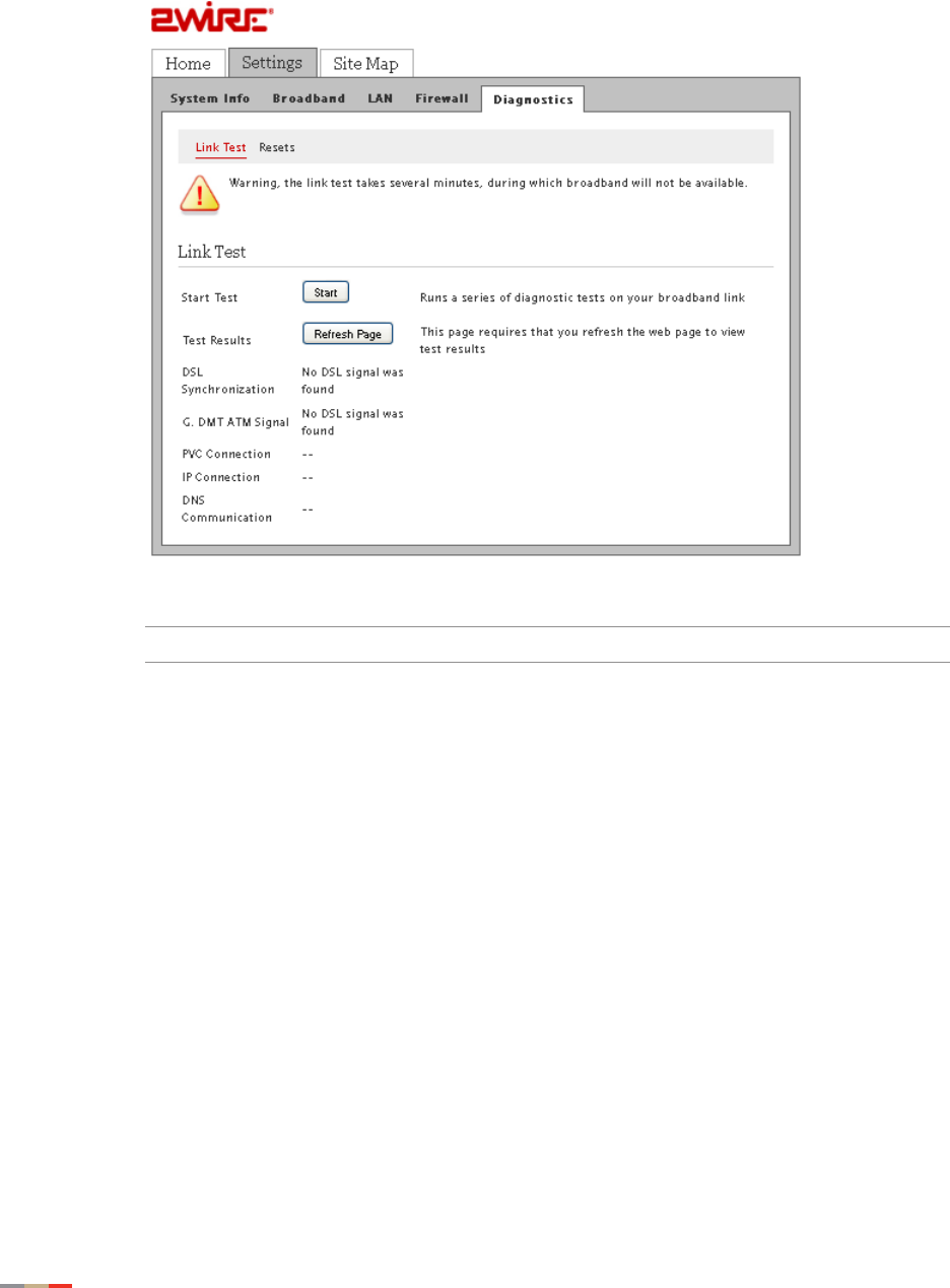
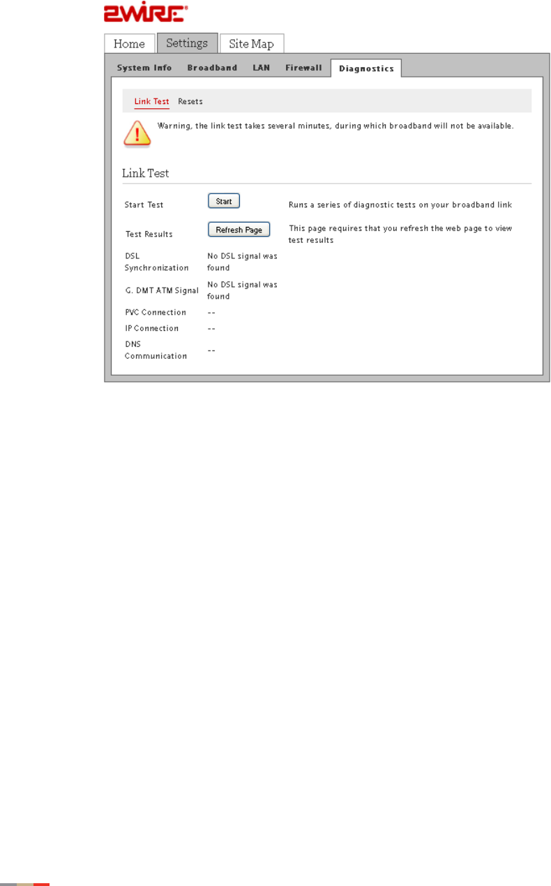
Performing Broadband Link Tests
Your gateway includes a test that helps you to diagnose broadband connection issues.
1. Open a Web browser and enter http://gateway.2Wire.net to access the gateway user
interface.
2. Click on the Home page; the Summary Status page opens.
CHAPTER 8: Finding Solutions
80 Performing Broadband Link Tests
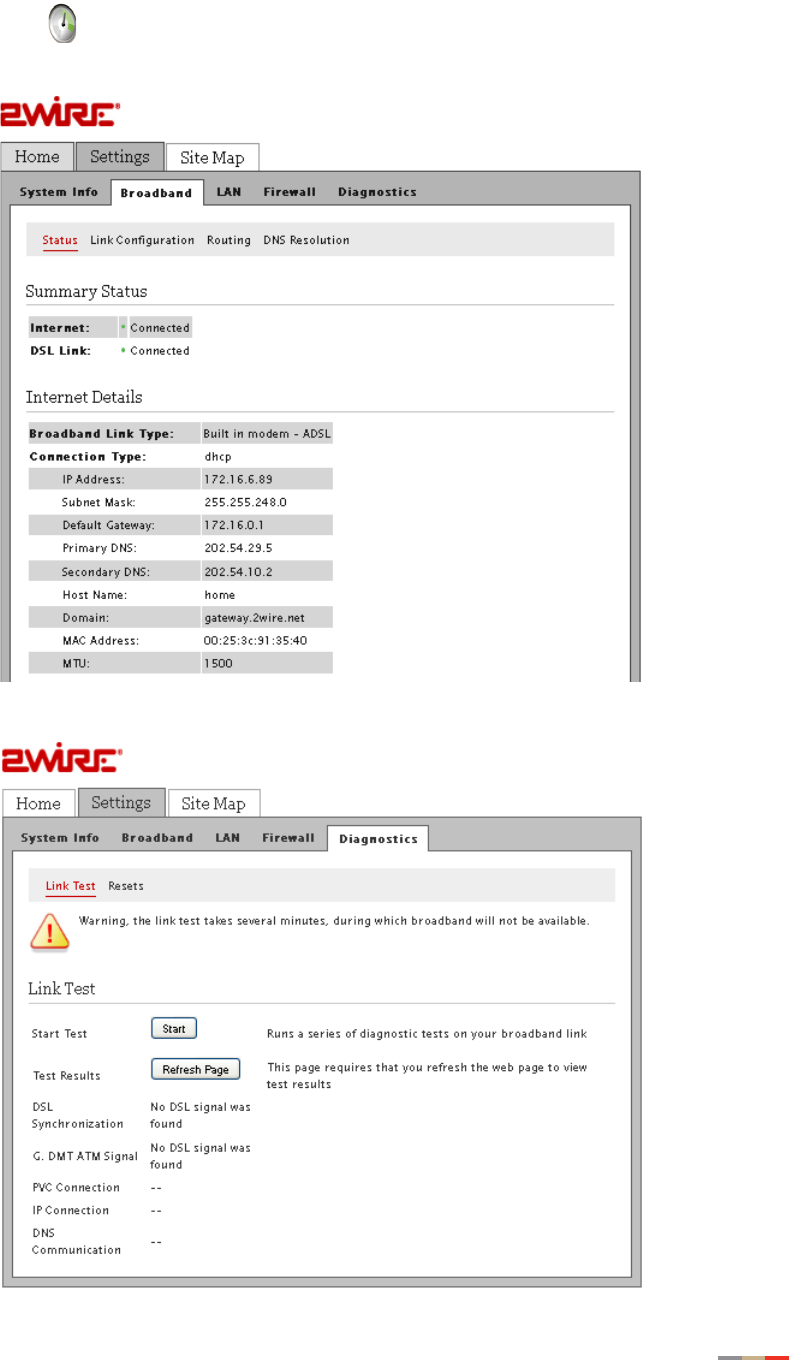
3. Click Diagnostics; the Link Test page opens.
4. Click Start; the gateway initiates the test, and displays the test results.
Note You will be unable to access the Internet when the test is taking place.
5. Interpret the issues:
• DSL issue indicates that the DSL service is not yet activated, and/or loose cable
connections on your gateway.
• IP connection issue indicates that your service provider’s network is unreachable.
• DNS issue indicates that the DNS servers within your service provider’s network are
unreachable.
Viewing the Gateway Information 81
CHAPTER 8: Finding Solutions
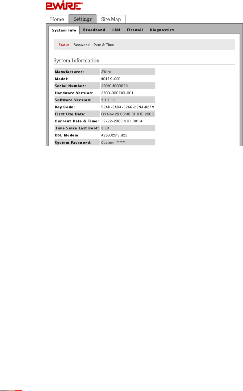
Viewing the Gateway Information
1. Open a Web browser and enter http://home, http://gateway.2Wire.net, or
http://192.168.1.254 to access the gateway user interface; the Home page opens.
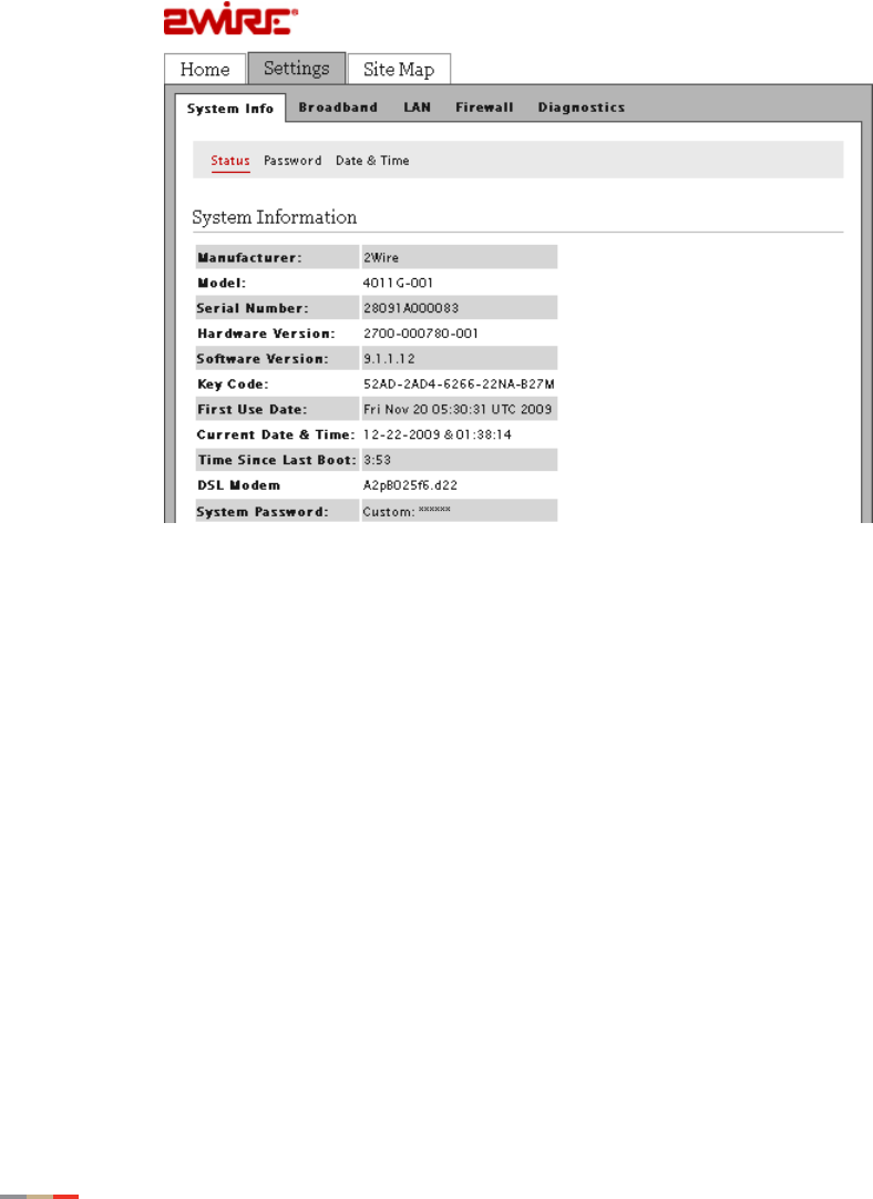
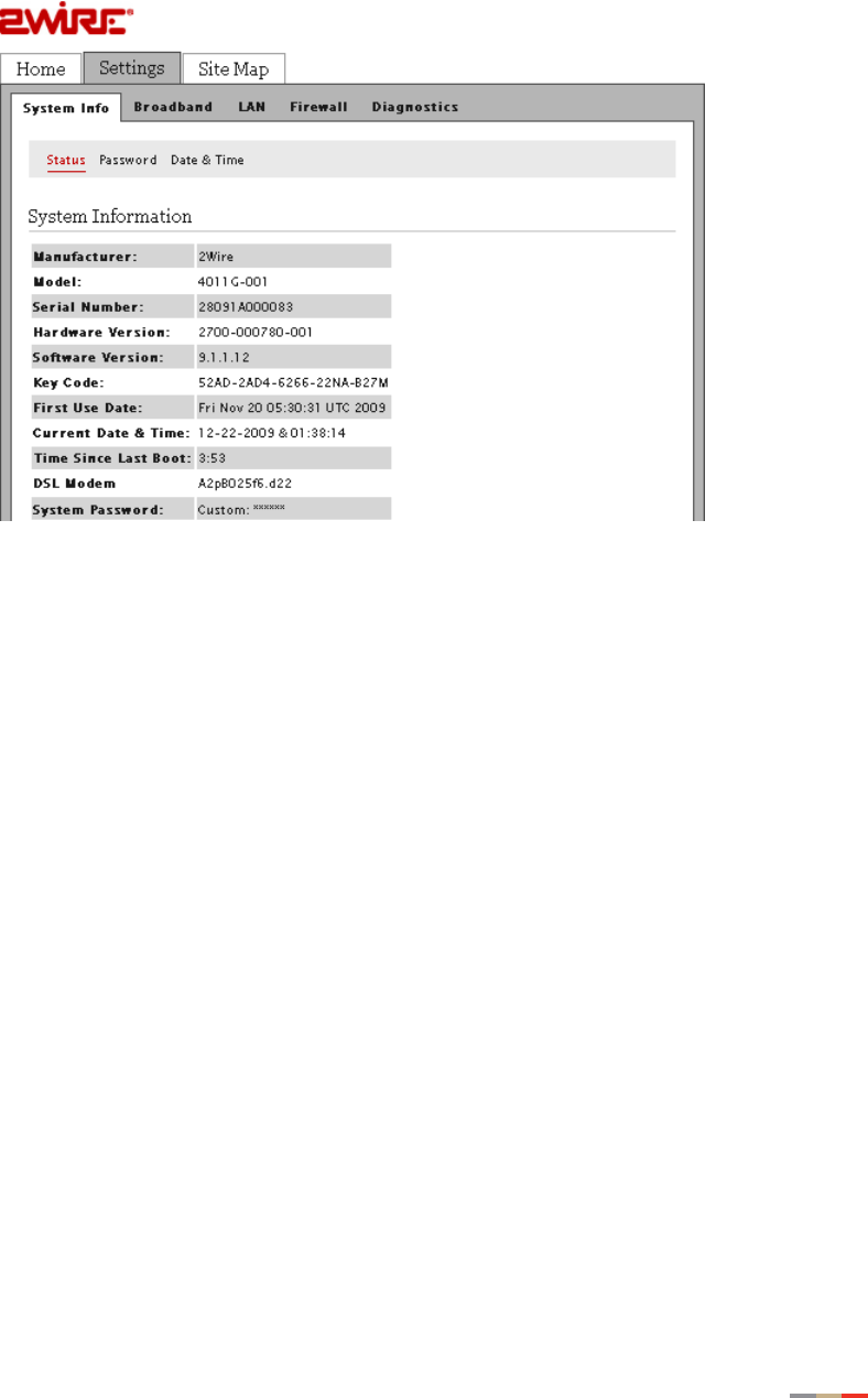
2. Click Settings; the System Information page opens, displaying read-only information, for
example,

CHAPTER 8: Finding Solutions
82 Viewing the Broadband Status
Viewing the Broadband Status
1. Open a Web browser and enter http://home, http://gateway.2Wire.net, or
http://192.168.1.254 to access the gateway user interface; the Home page opens.
Viewing the Broadband Status 83
CHAPTER 8: Finding Solutions
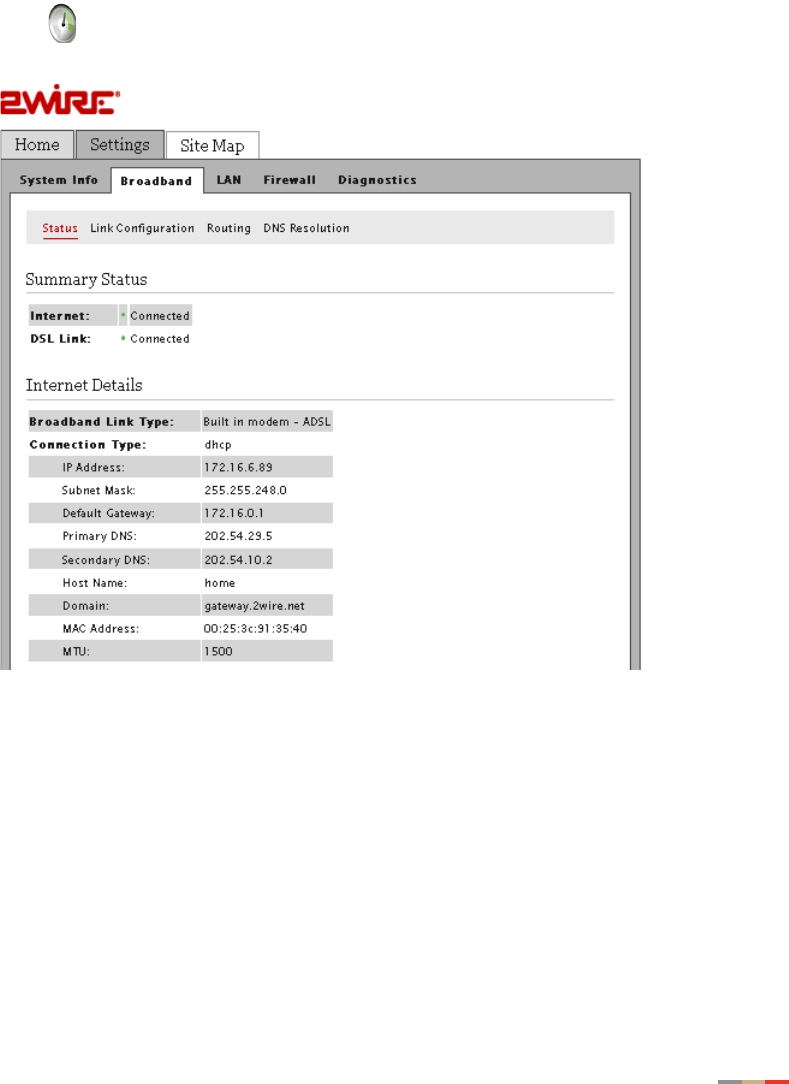
2. Click on the Home page; the Summary Status page opens.
CHAPTER 8: Finding Solutions
84 Viewing the Broadband Status
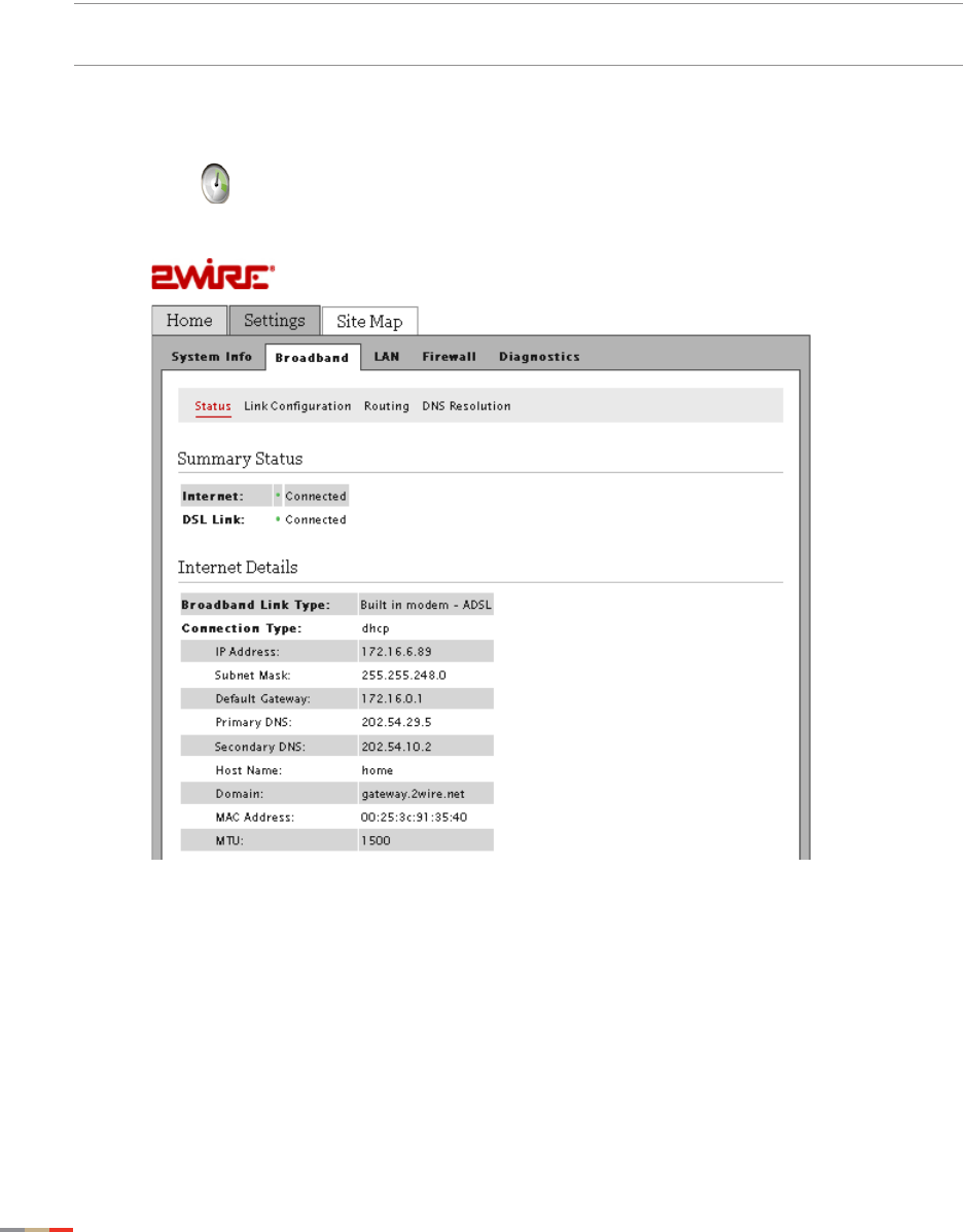
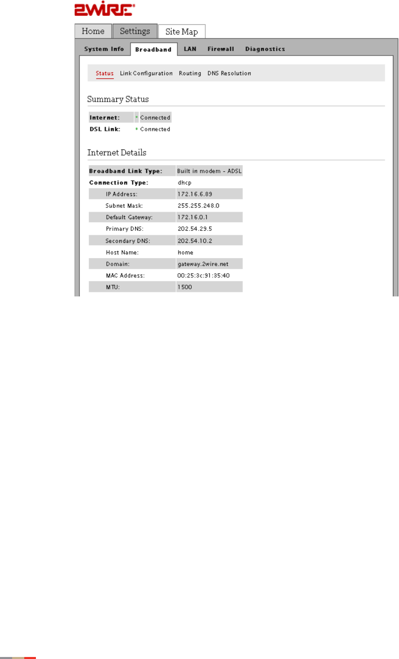
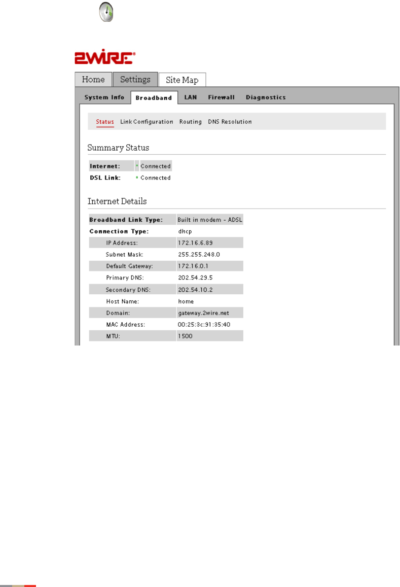
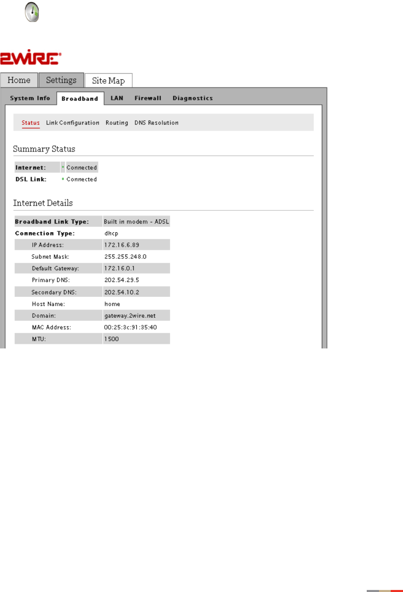
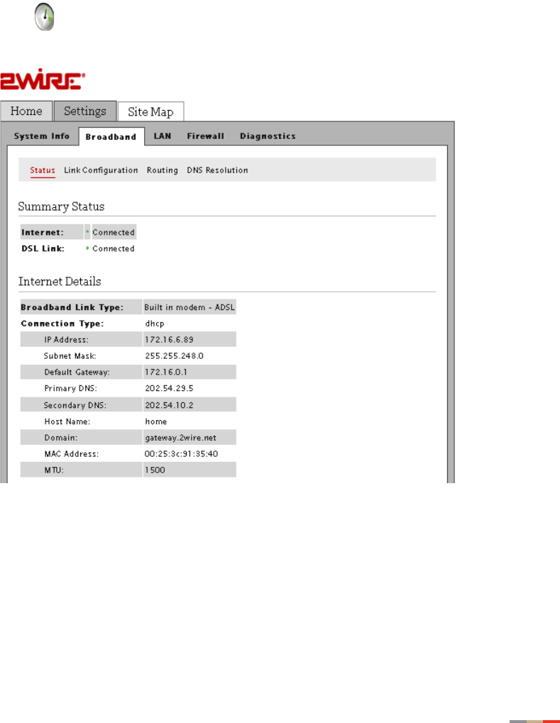
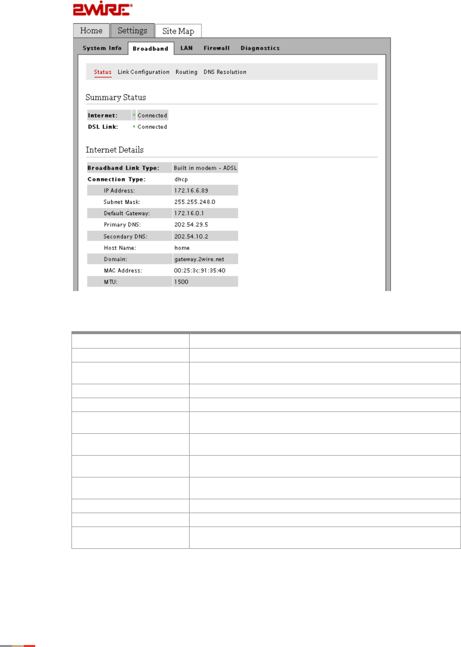
3. View the Internet information:
Item Description
Broadband Link Type Built-in ADSL Modem or External Broadband Modem via Ethernet.
Connection Type The method by which the gateway connects to the ISP:
Direct_IP, DHCP, PPPoA, or PPPoE.
IP Address The broadband address of your gateway.
Subnet Mask The subnet mask to be used by the gateway on the broadband link.
Default Gateway The IP address of the default gateway (default router) that the gateway
connects to on the broadband link.
Primary DNS The IP address of the primary DNS server that the gateway is to use for
DNS name resolution on the broadband link.
Secondary DNS The IP address of the secondary DNS server the gateway uses for DNS
name resolution on the broadband link.
Host Name The gateway host name. This field is present only if a host name has
been configured.
Domain The domain name associated with the gateway on the broadband link.
MAC Address The gateway MAC address.
MTU The maximum size of the packets (in bytes) sent from a computer to the
network.

Viewing the LAN Status 85
CHAPTER 8: Finding Solutions
Viewing the LAN Status
1. Open a Web browser and enter http://home, http://gateway.2Wire.net, or
http://192.168.1.254 in the address line; the Home page opens.
CHAPTER 8: Finding Solutions
86 Viewing the LAN Status
2. Click Settings; the System Information page opens.
Viewing the LAN Status 87
CHAPTER 8: Finding Solutions
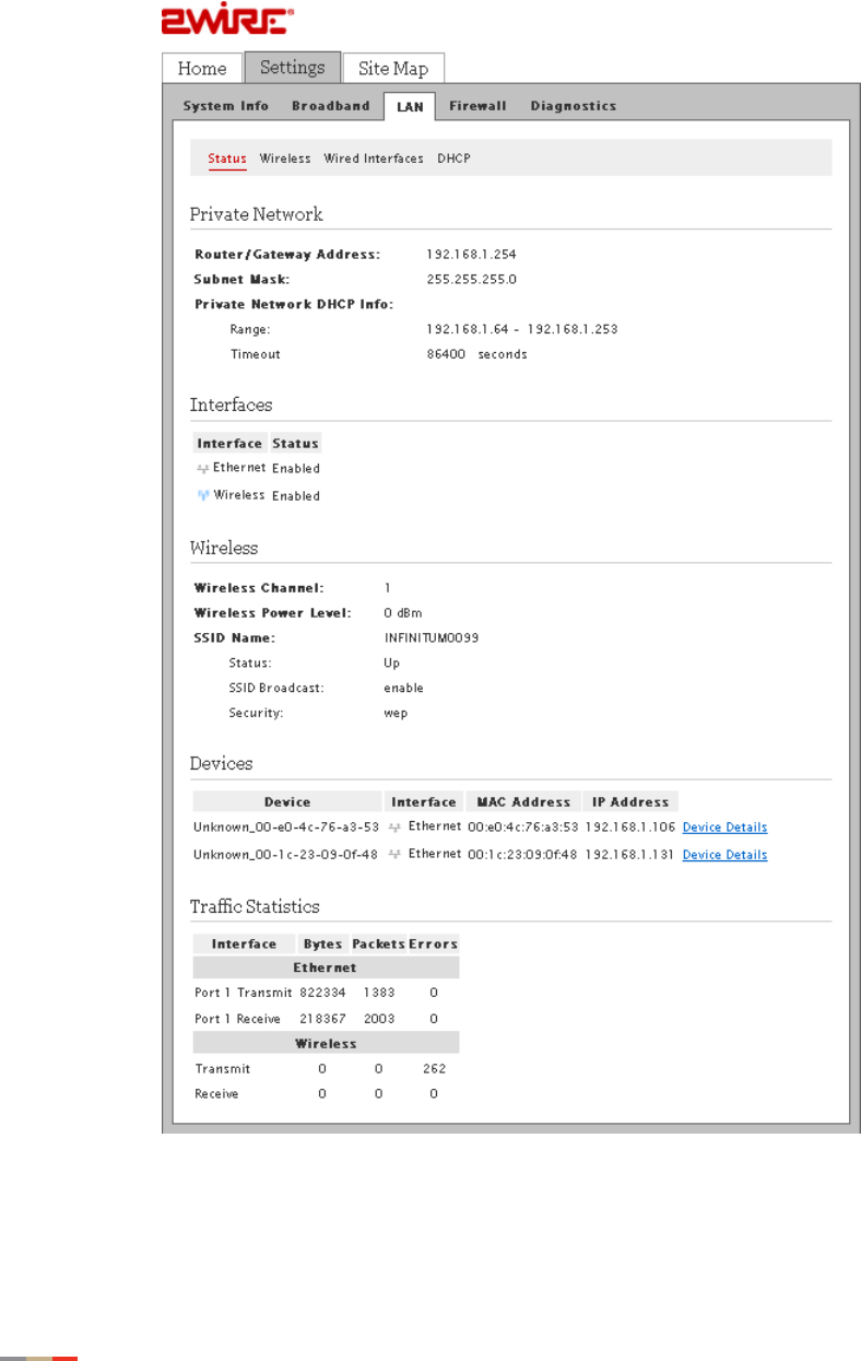
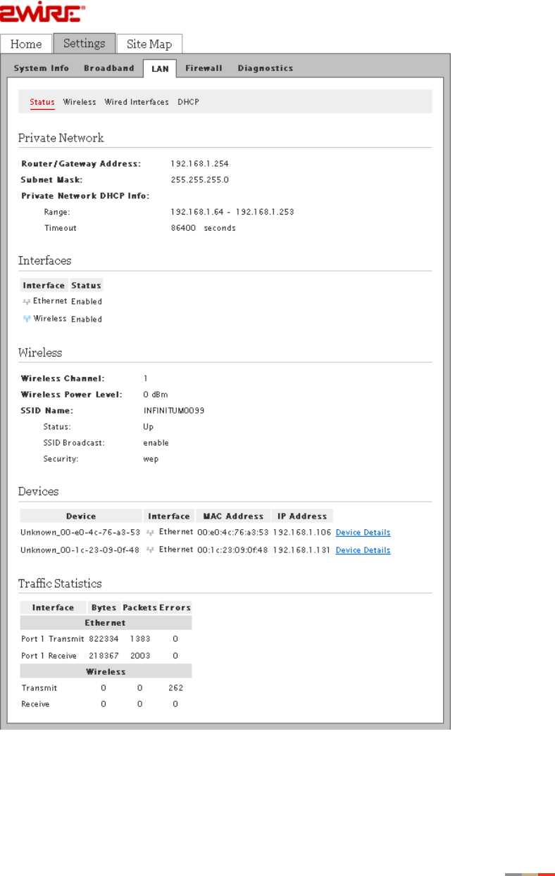
3. Click LAN; a page similar to the following opens, displaying the private network
information and LAN devices connected to your network.
CHAPTER 8: Finding Solutions
88 Resetting the Gateway
Resetting the Gateway
Resetting the gateway may cause your broadband connection to not function properly and may
require reconfiguration of the system to reconnect the broadband service.
1. Open a Web browser and enter http://home, http://gateway.2Wire.net, or
http://192.168.1.254 in the address line; the Home page opens.
Resetting the Gateway 89
CHAPTER 8: Finding Solutions
2. Click on the Home page; the Summary Status page opens.
3. Click Diagnostics; the Link Test page opens.
CHAPTER 8: Finding Solutions
90 Resetting the Gateway
4. Click Resets; the following page opens.
5. Click the button you want to clear or reset.
•Clear Device List. The Clear button clears all devices from the Local Network list.
•Reset IP/PPP. The Reset button resets the PPP connection and/or releases and
renews the broadband IP address.
•Reset Broadband. The Reset button re-establishes the broadband link.
•Reset System. The Reboot button allows you to restart the gateway.
•Reset to Factory Default State. The Reset button resets the gateway to an
unprovisioned default state. Doing so will remove all your saved configuration
settings, while resetting them to their respective default factory settings.