ARRIS SVG2500 SURFboard Voice Gateway User Manual SURFboard Wireless Voice Gateway
ARRIS Group, Inc. SURFboard Voice Gateway SURFboard Wireless Voice Gateway
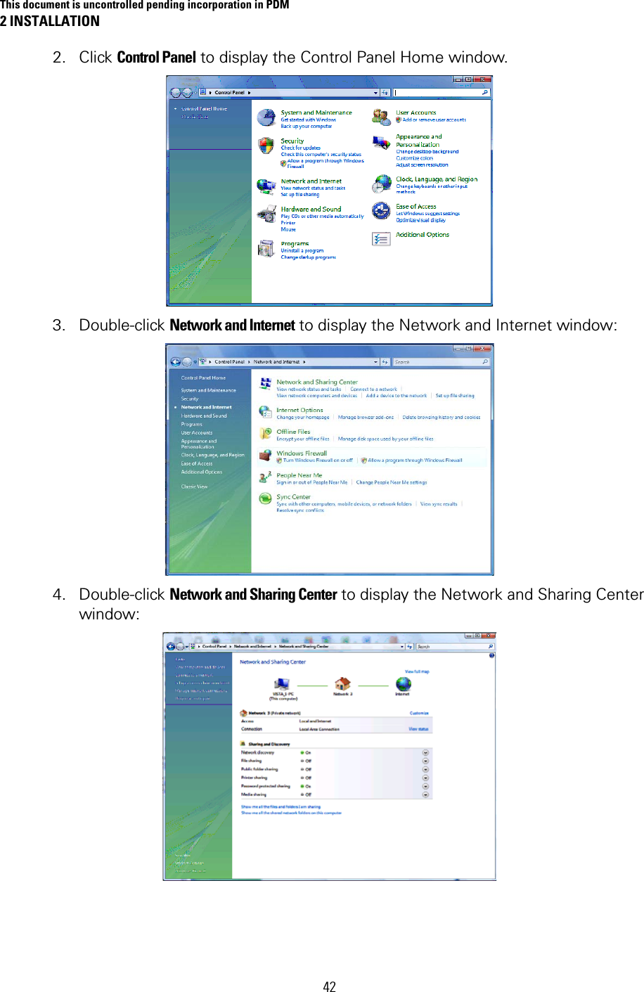
ARRIS >
Contents
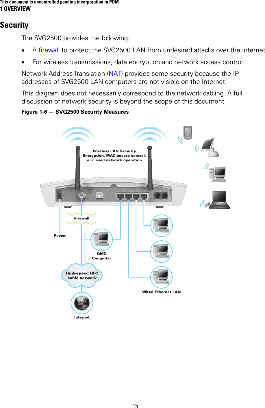
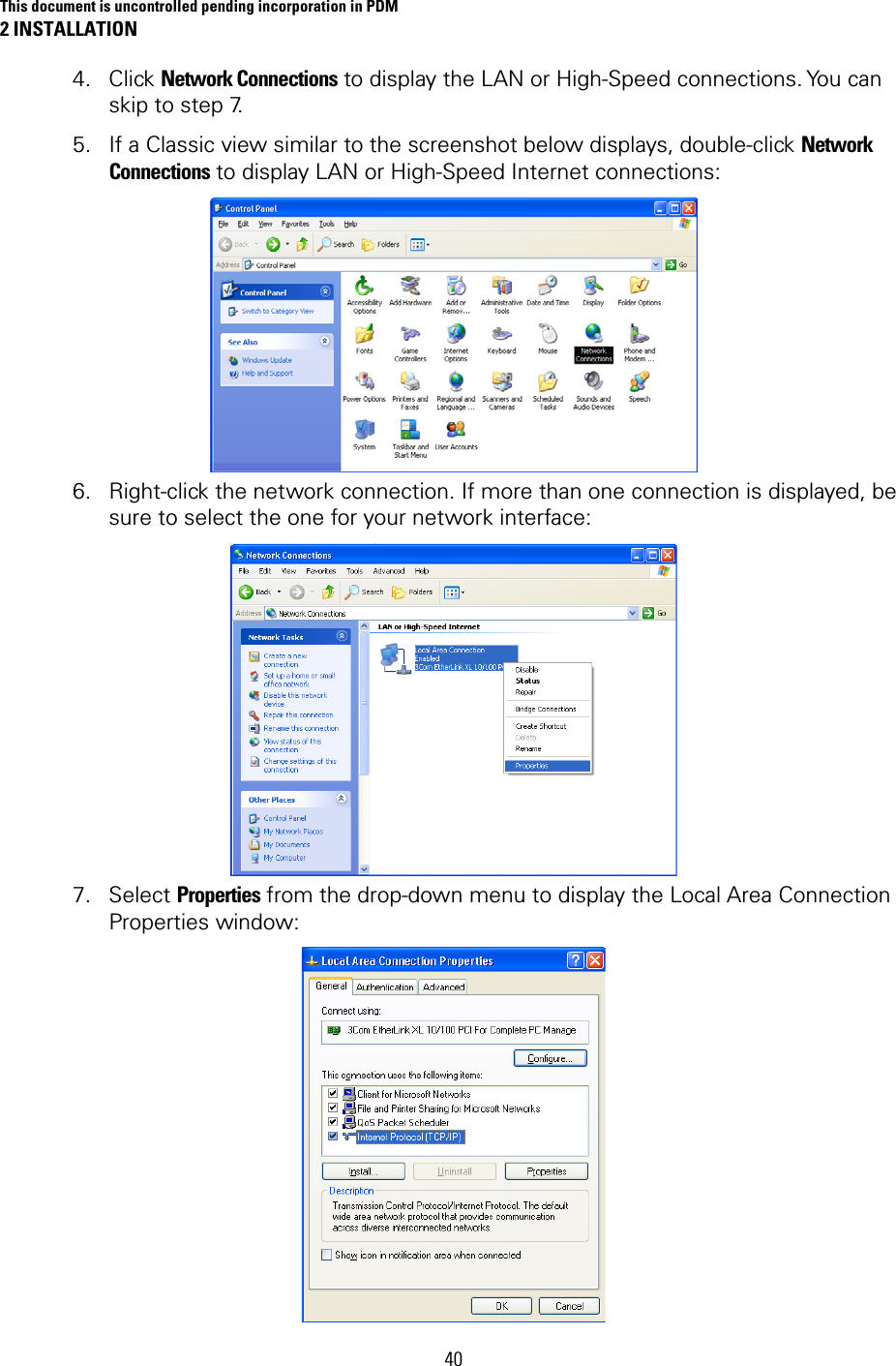
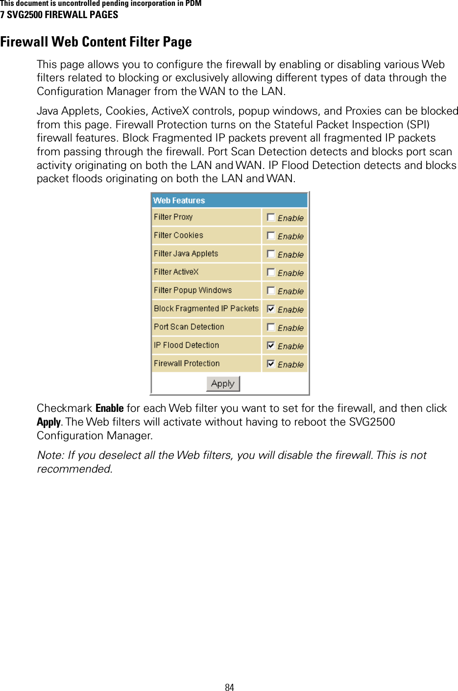
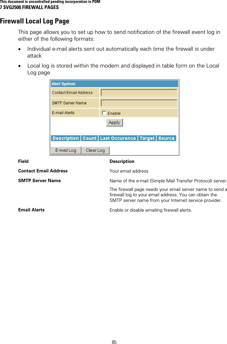
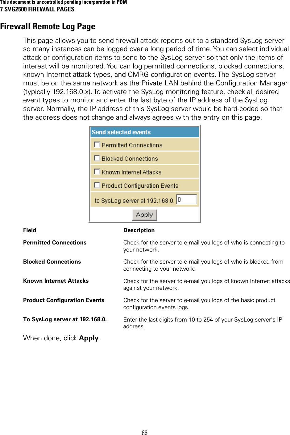
- 1. Manual Part 1
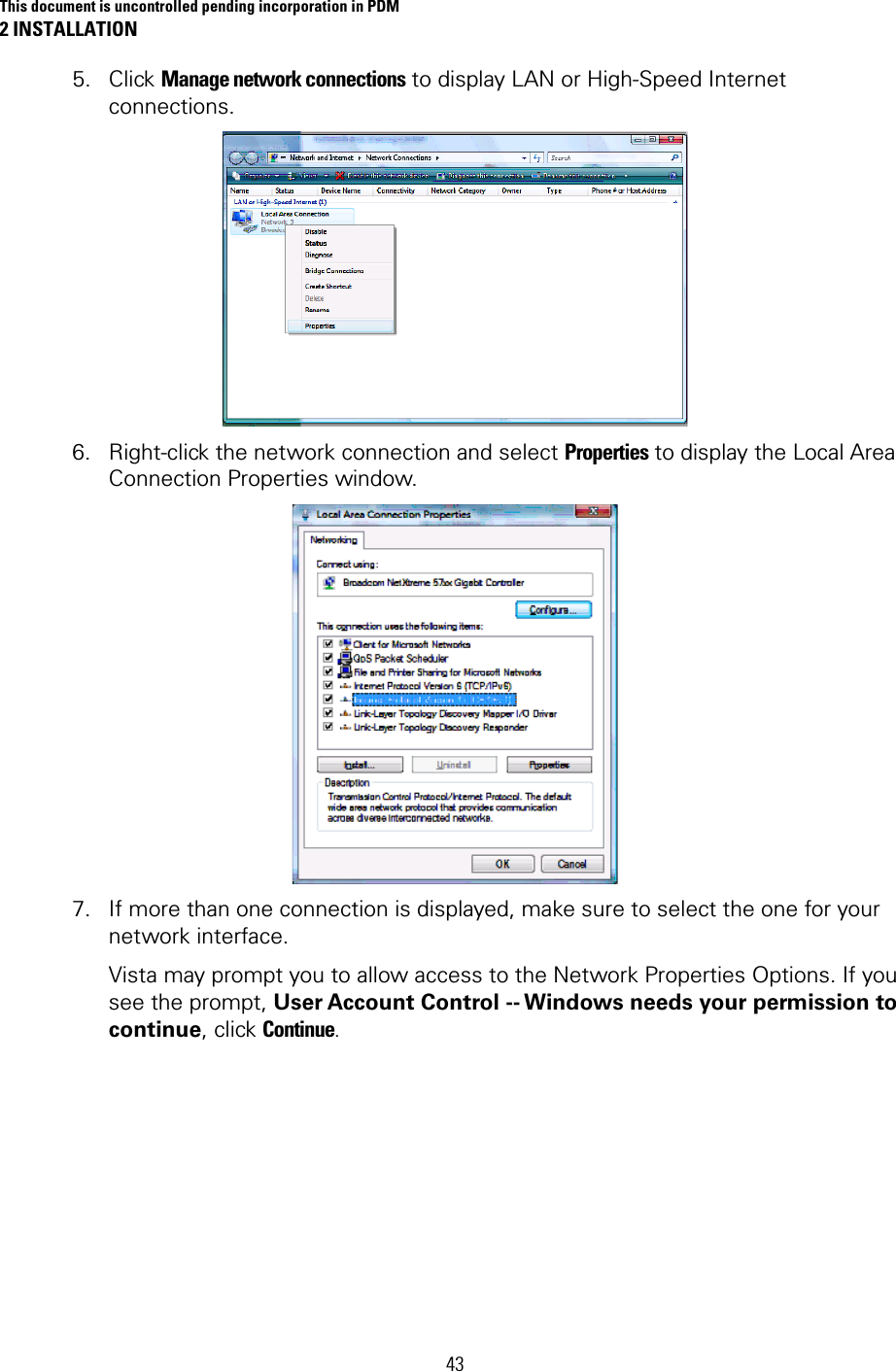
- 2. Manual Part 2
- 3. Manual Part 3
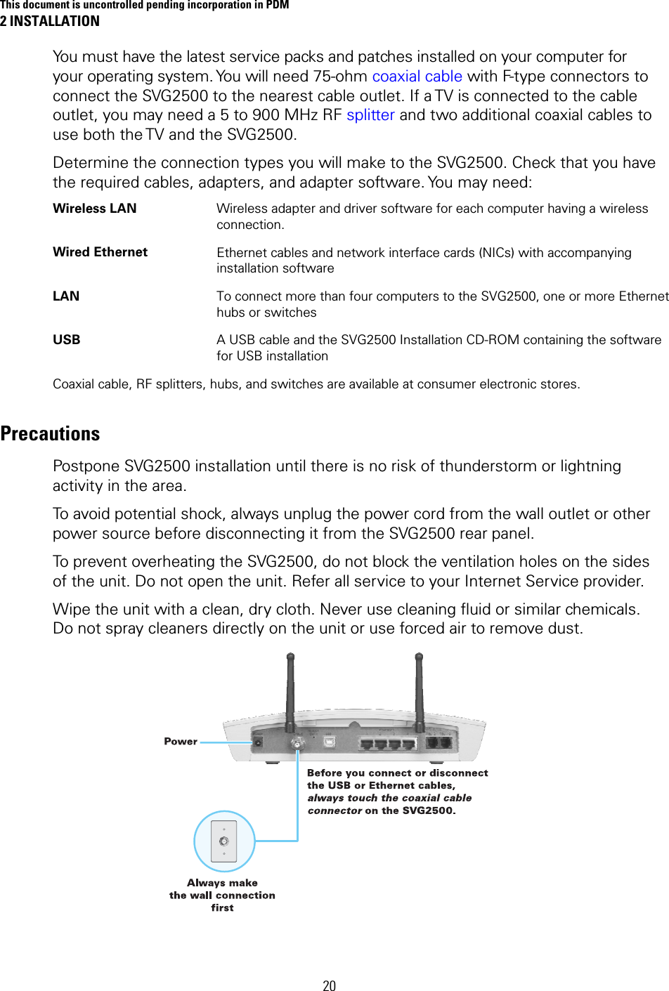
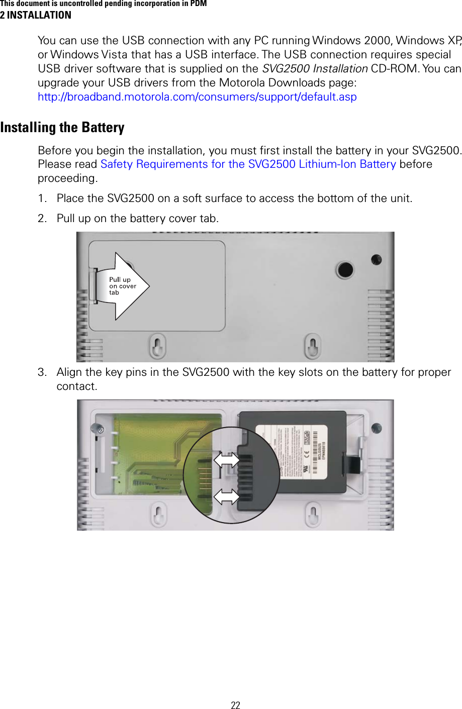
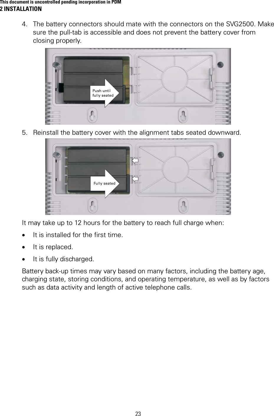
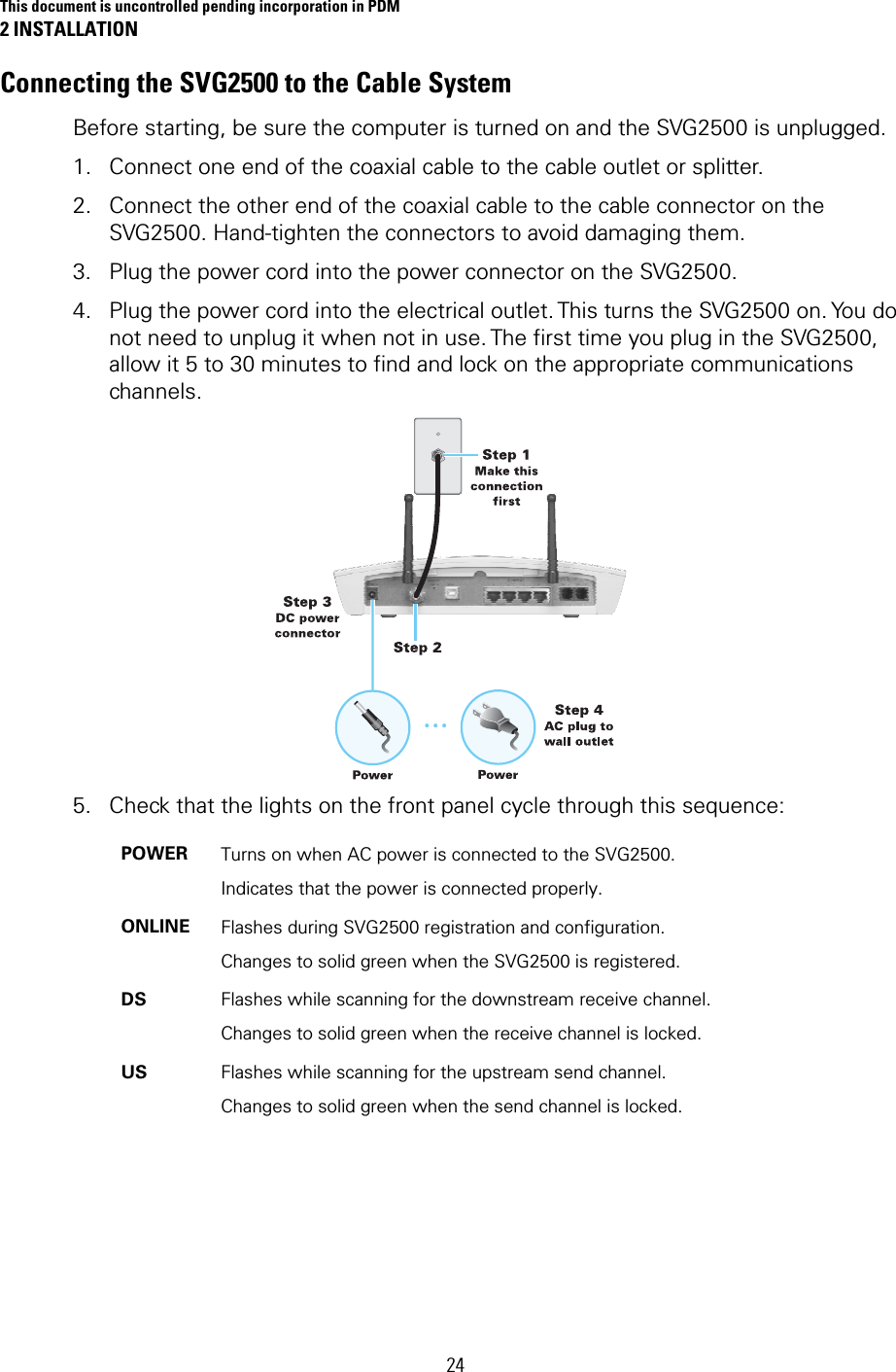
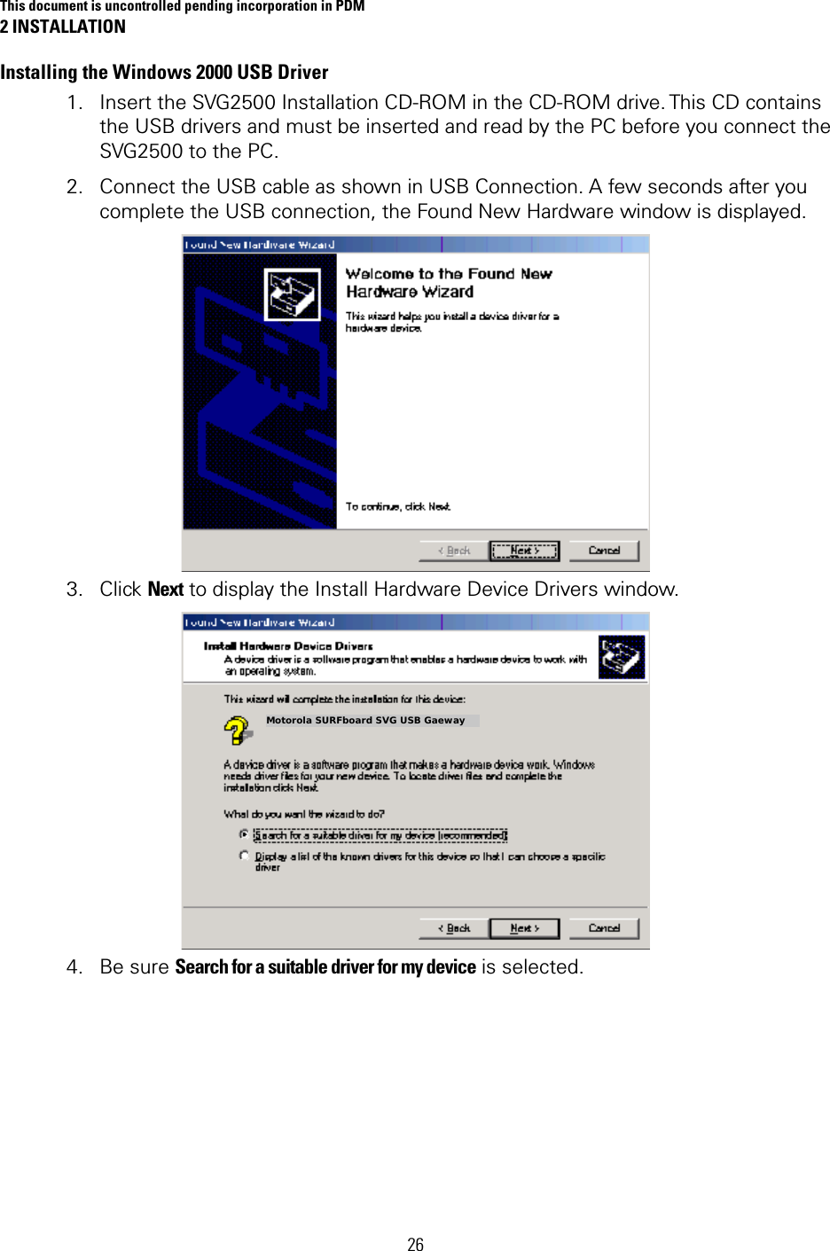
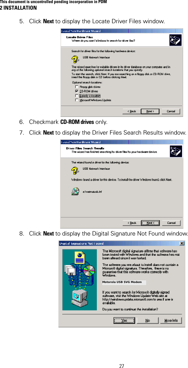
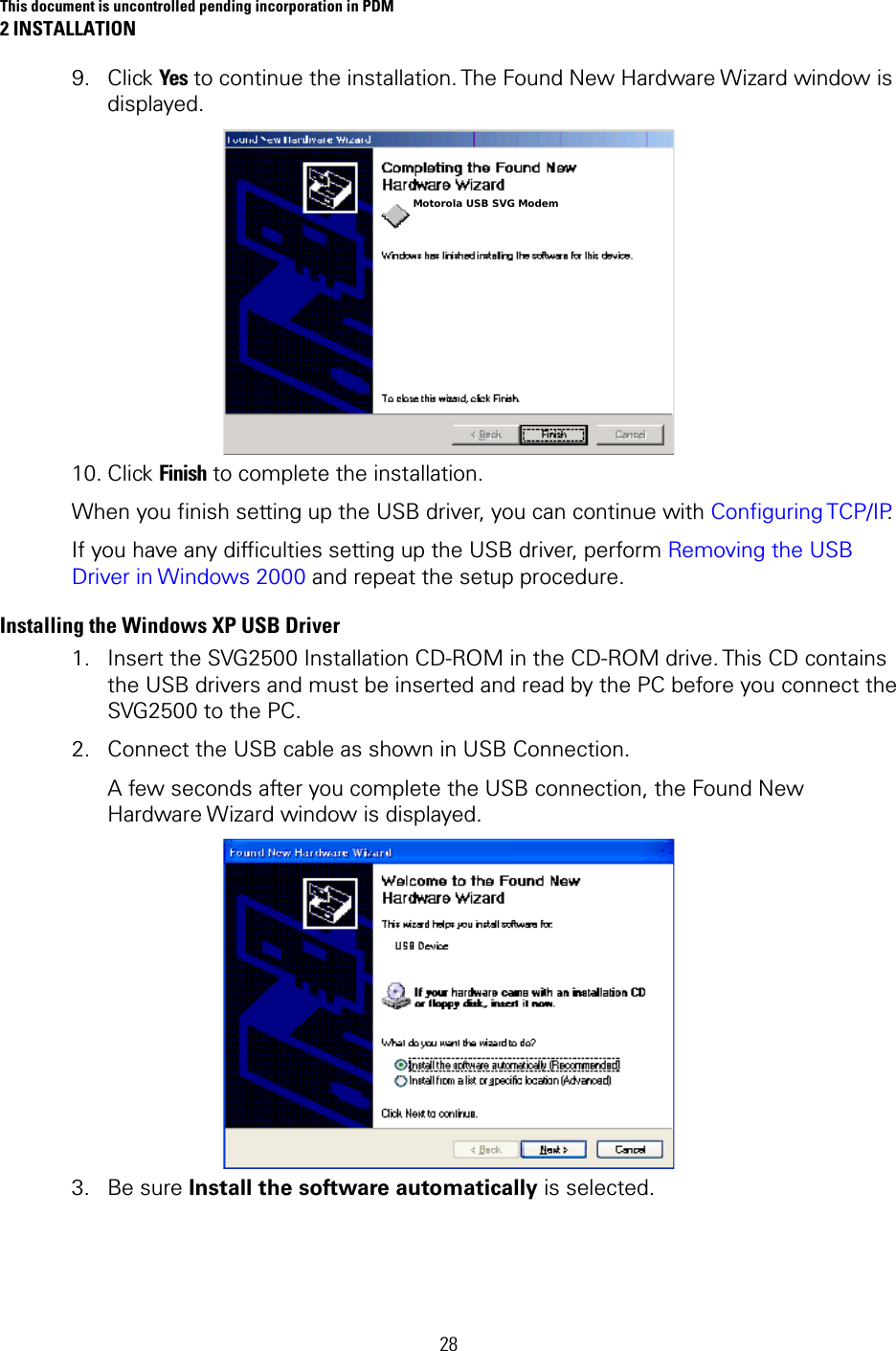
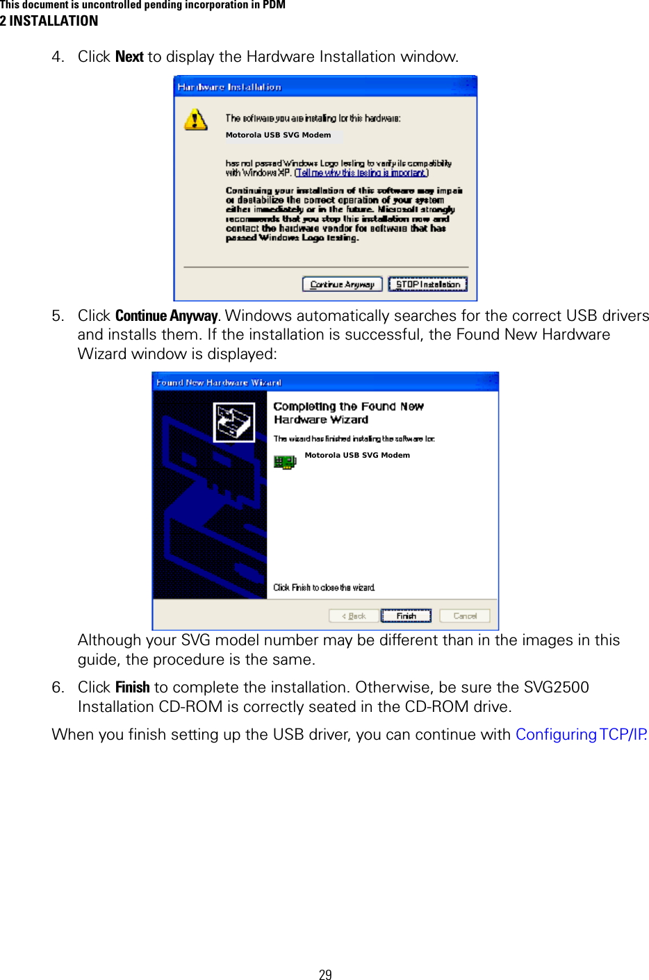
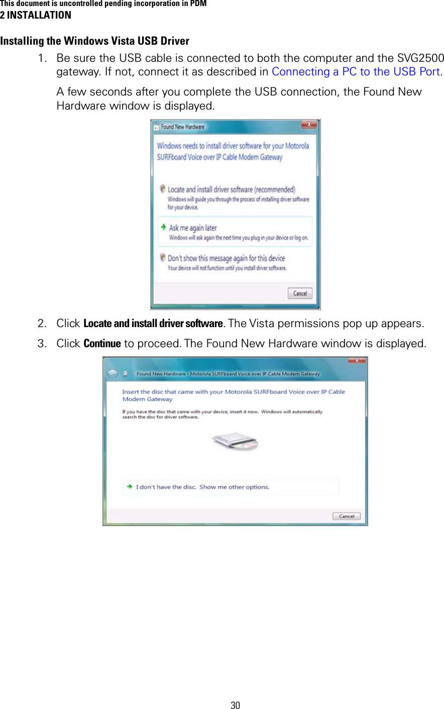
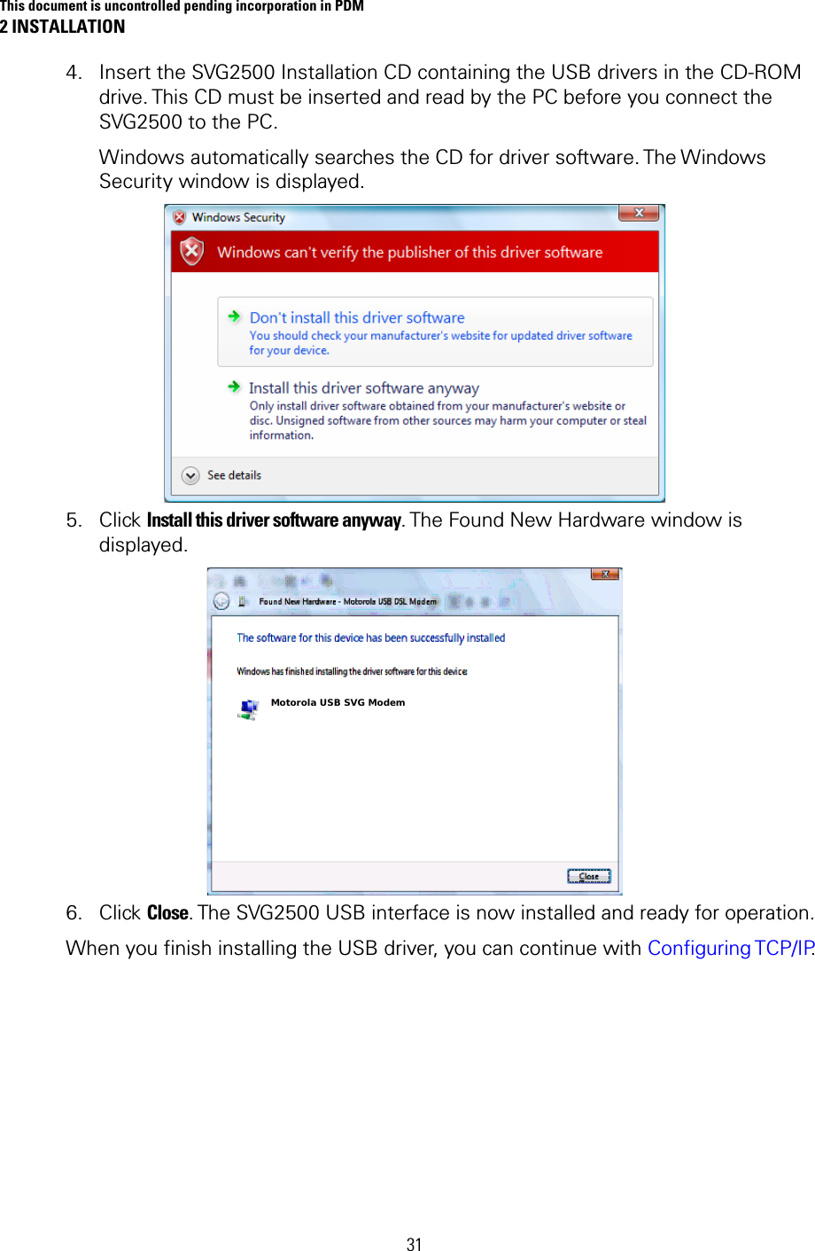
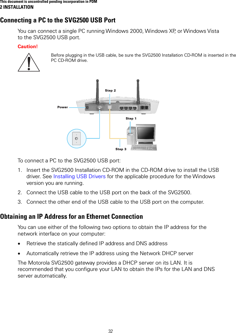
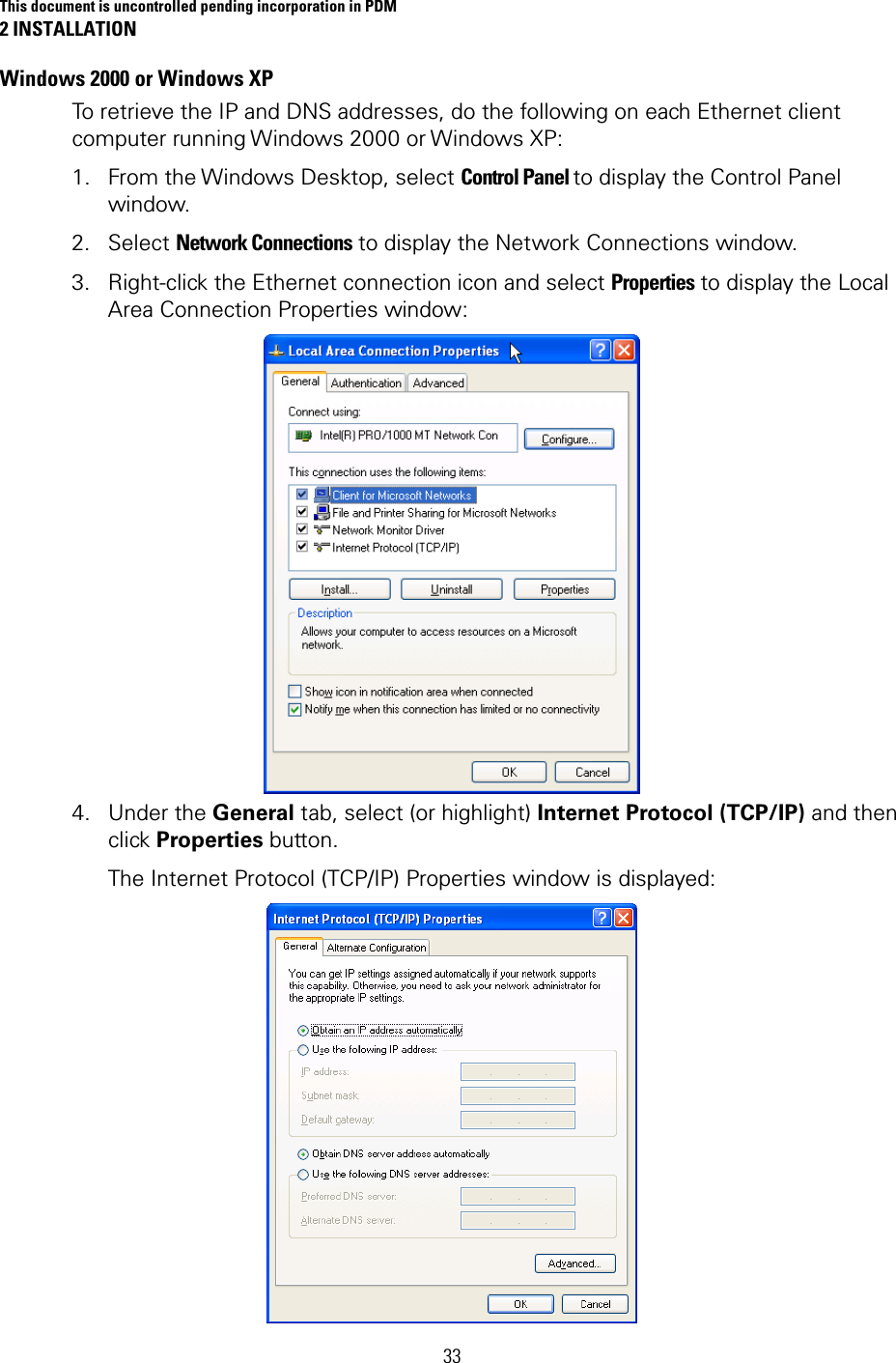
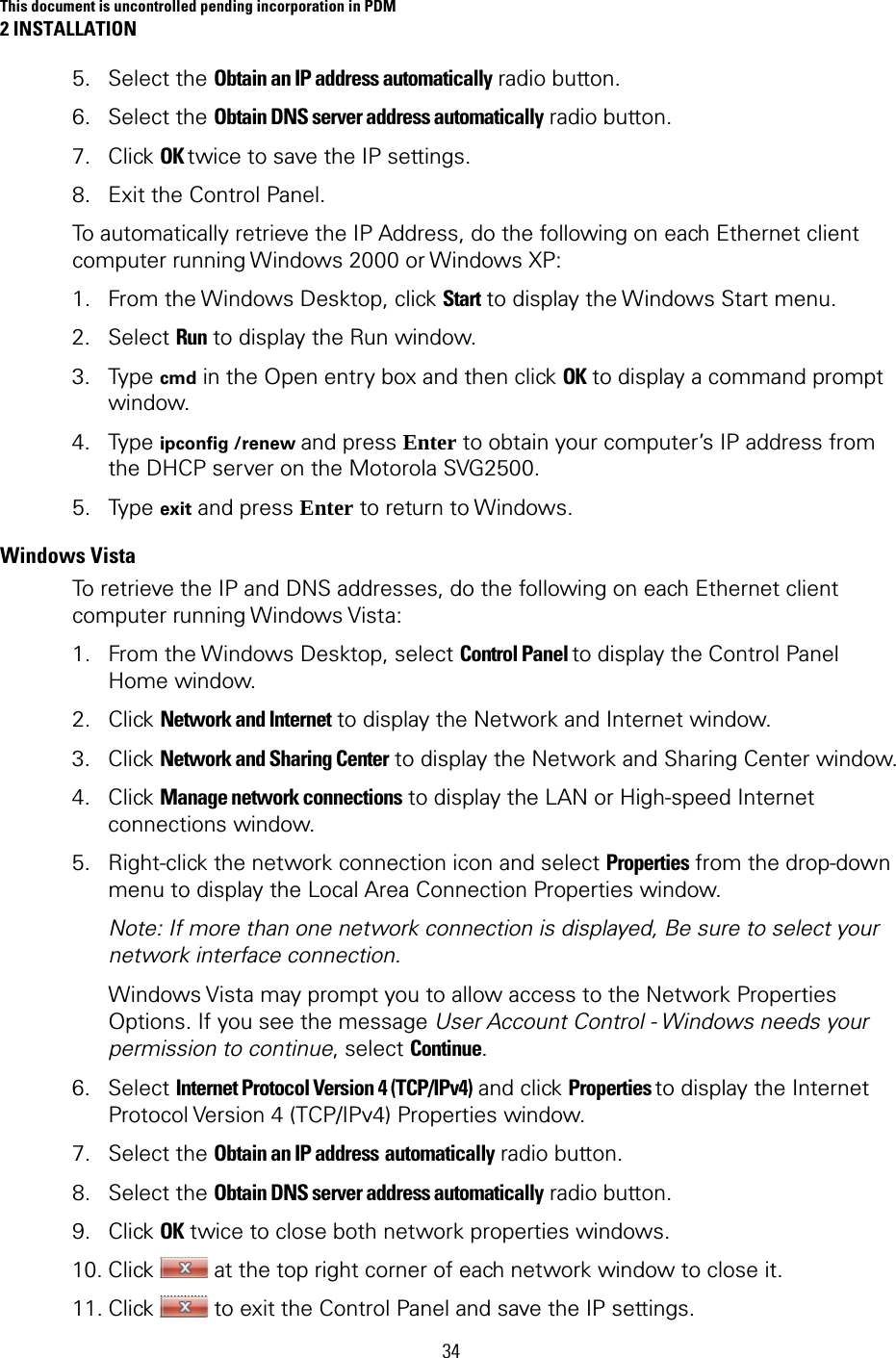
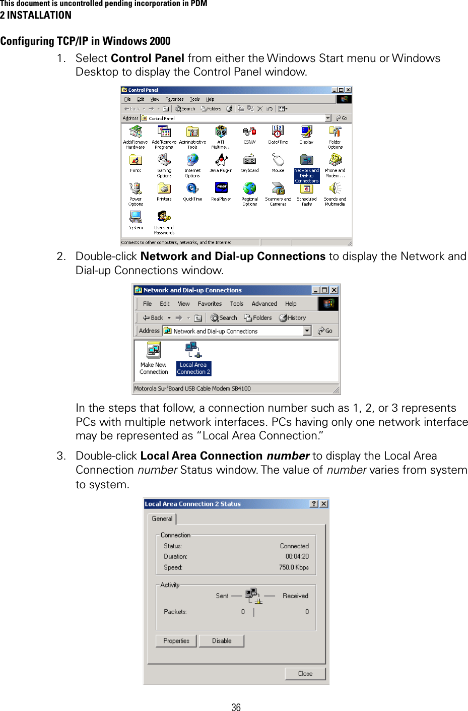
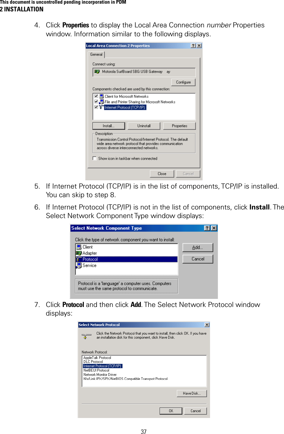
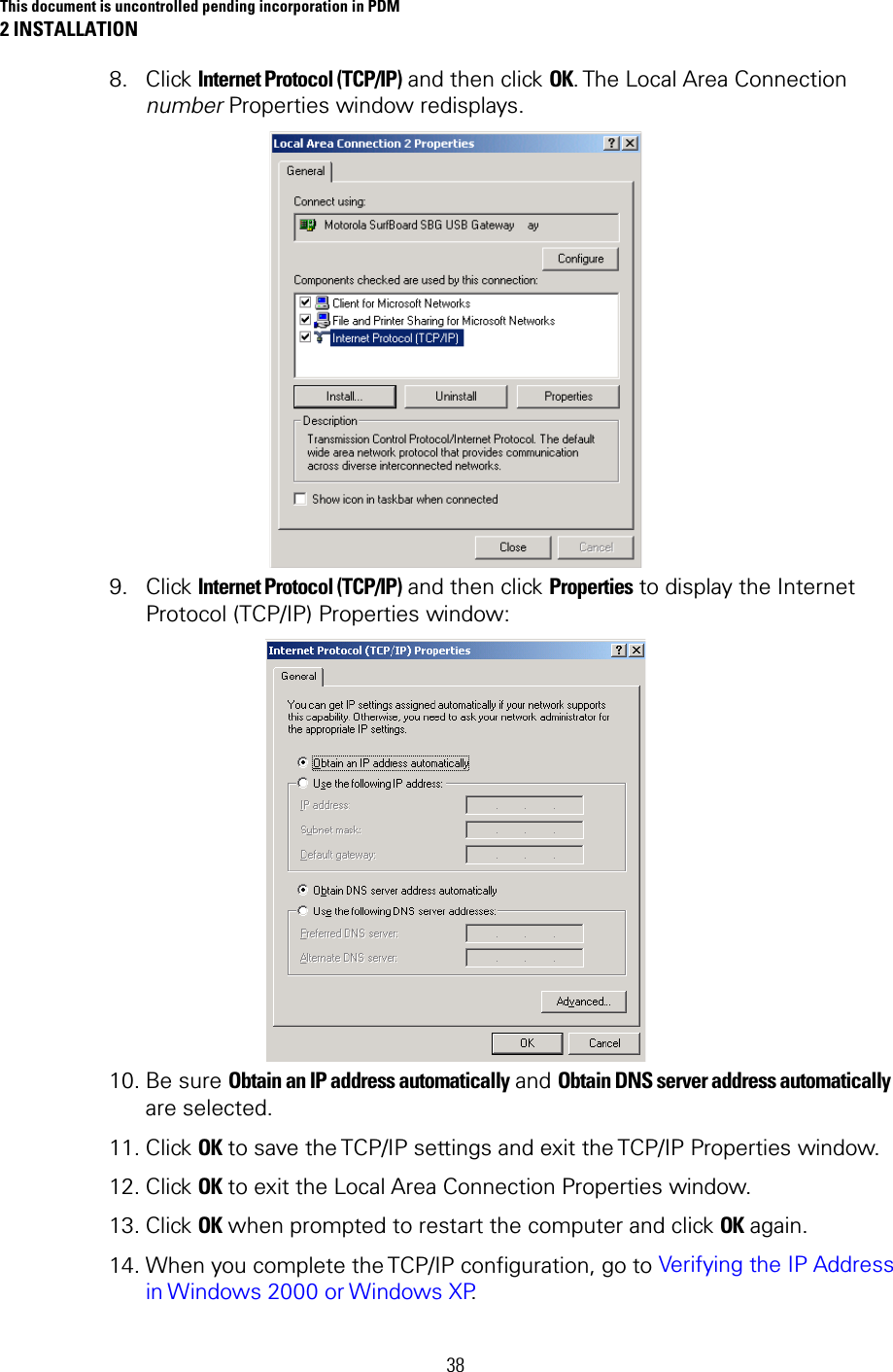
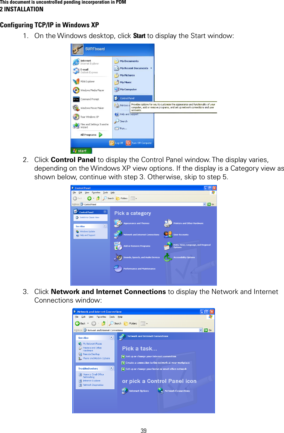
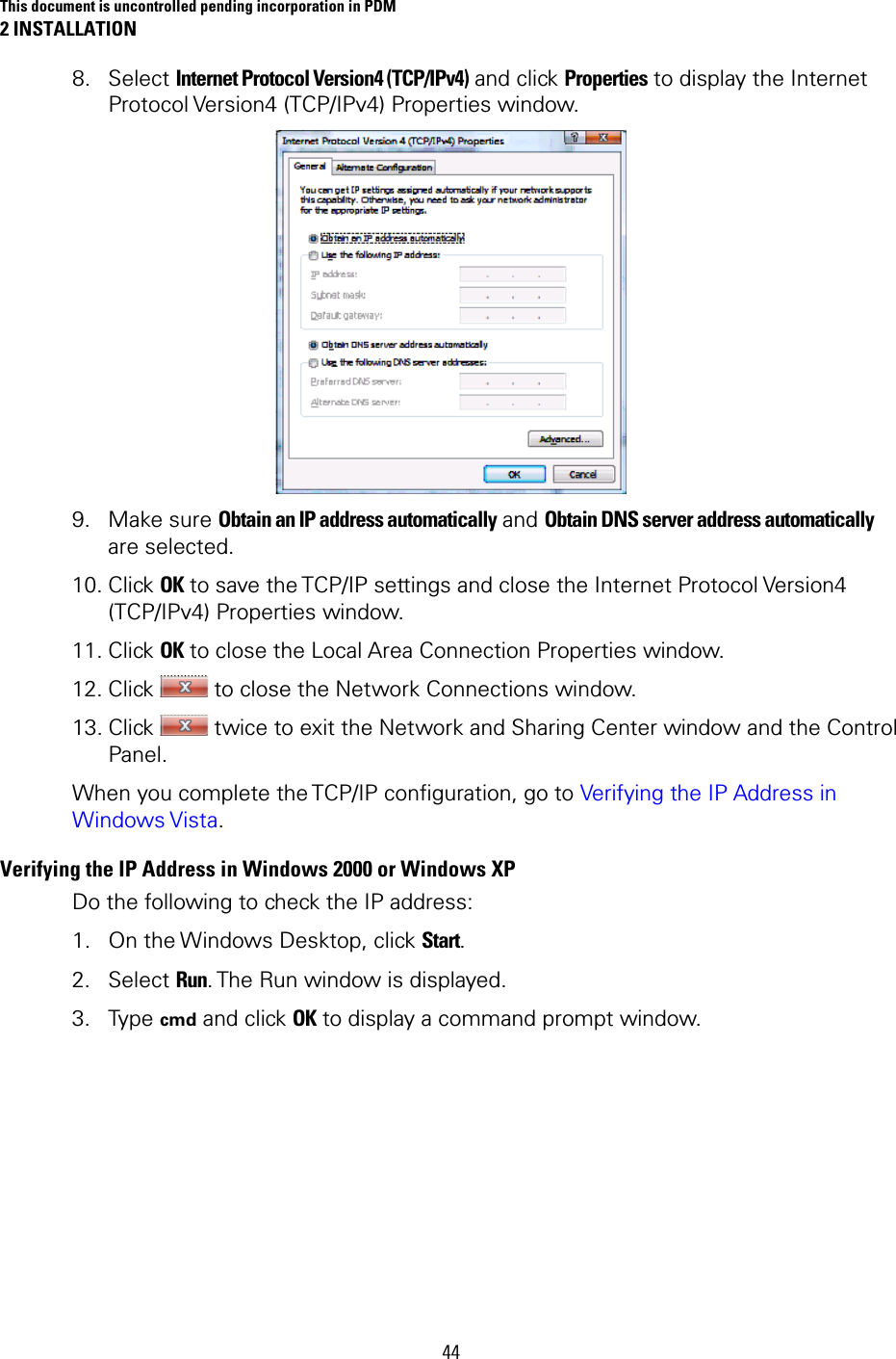
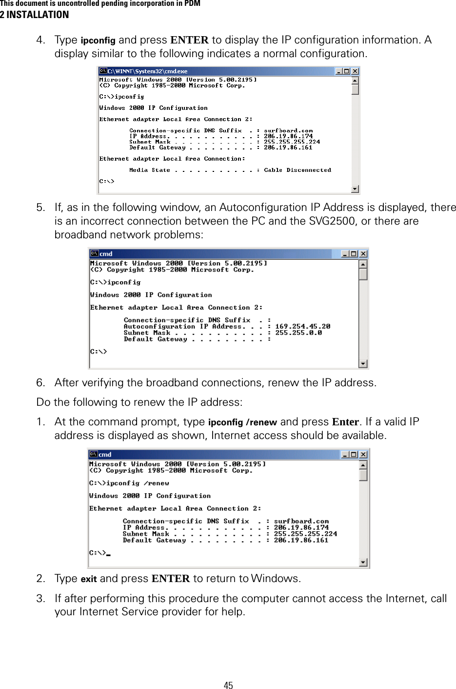
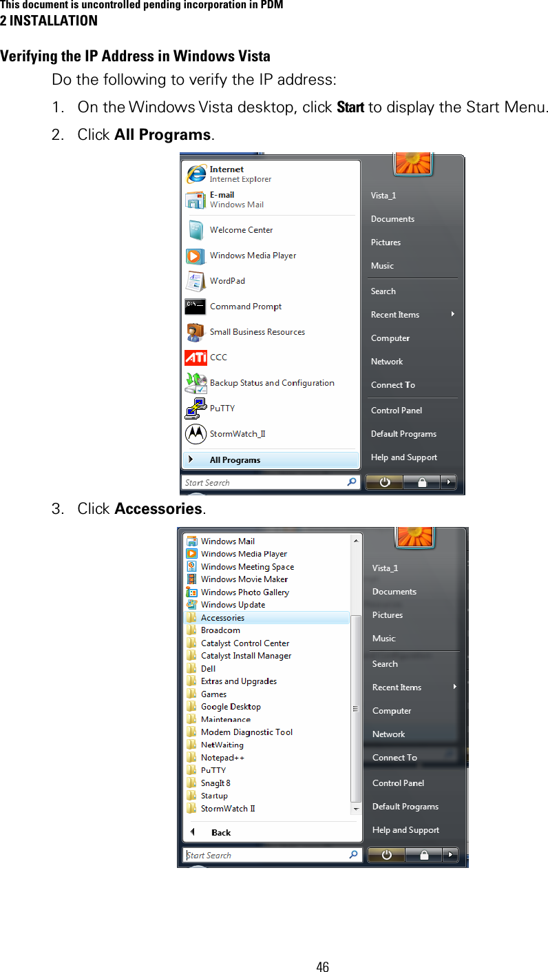
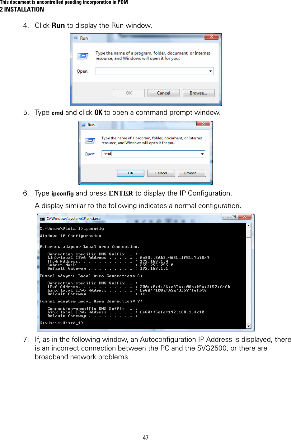
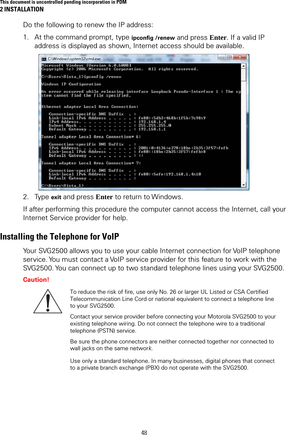
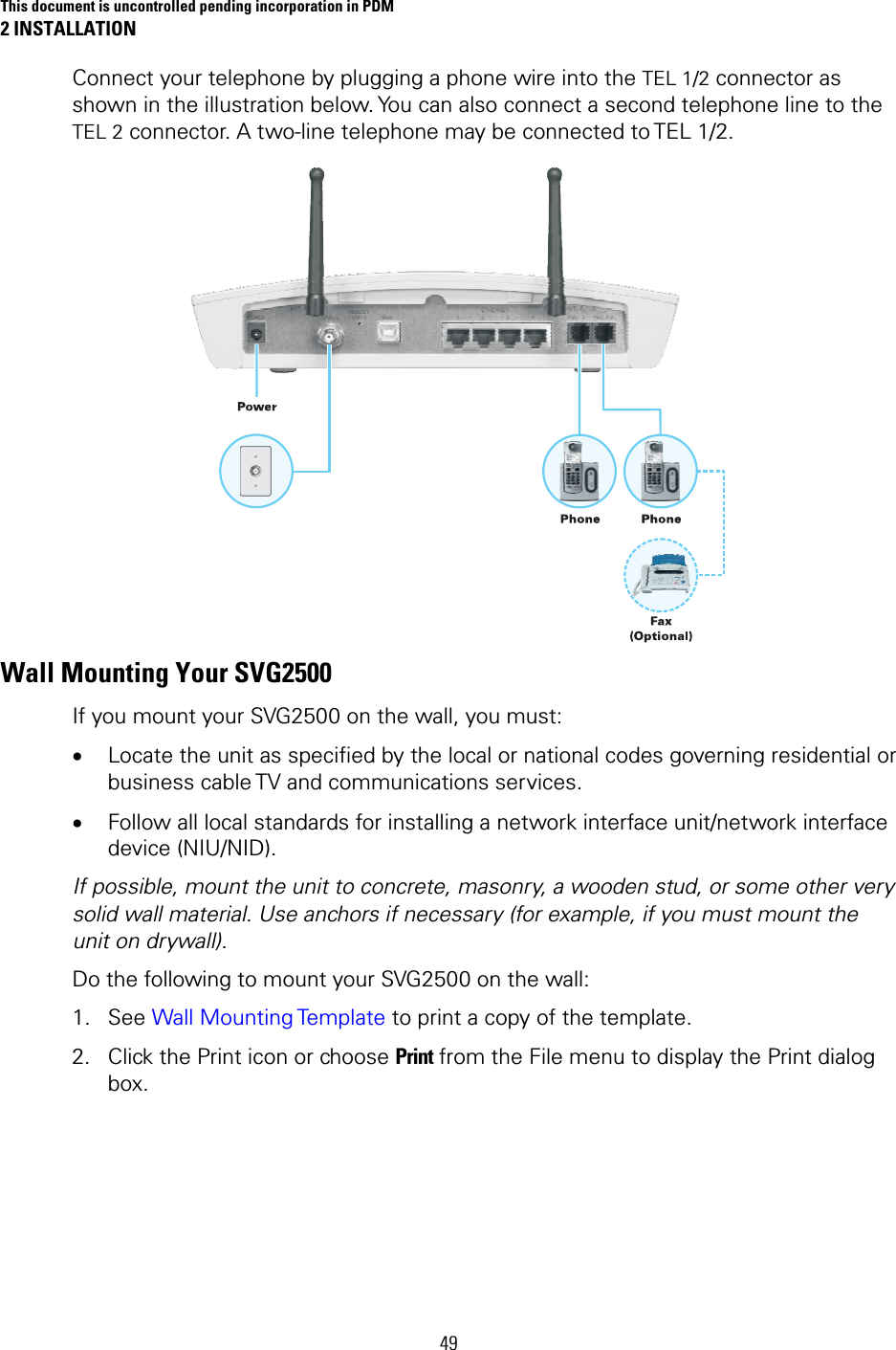
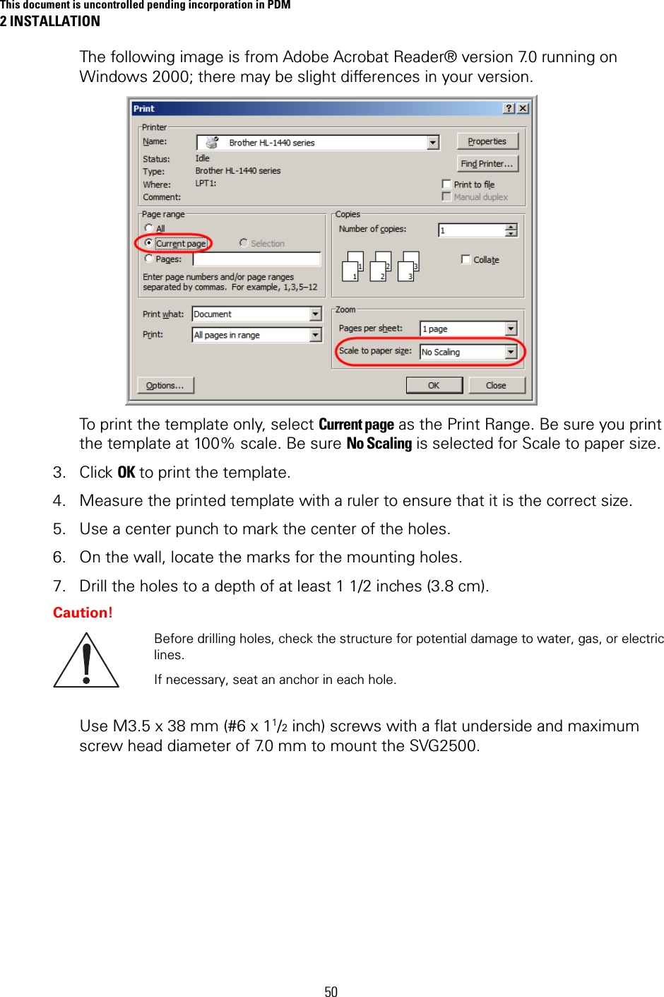
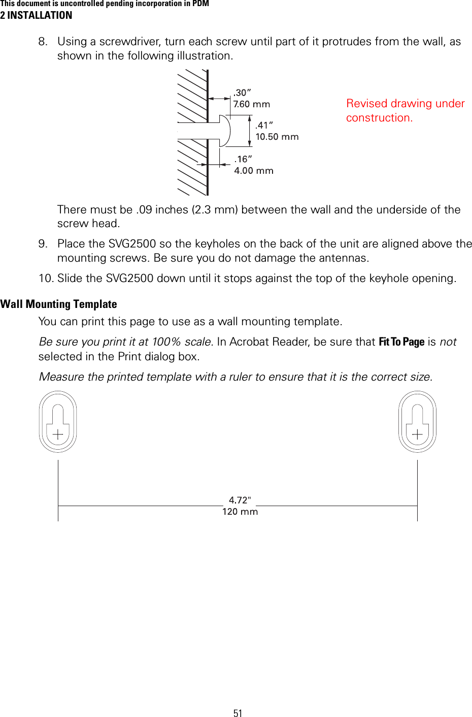
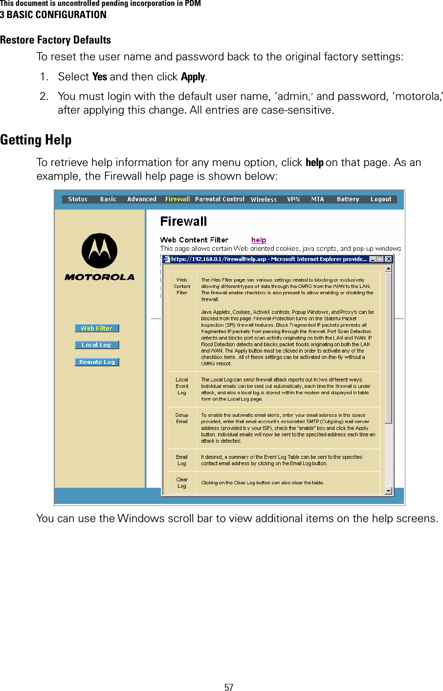
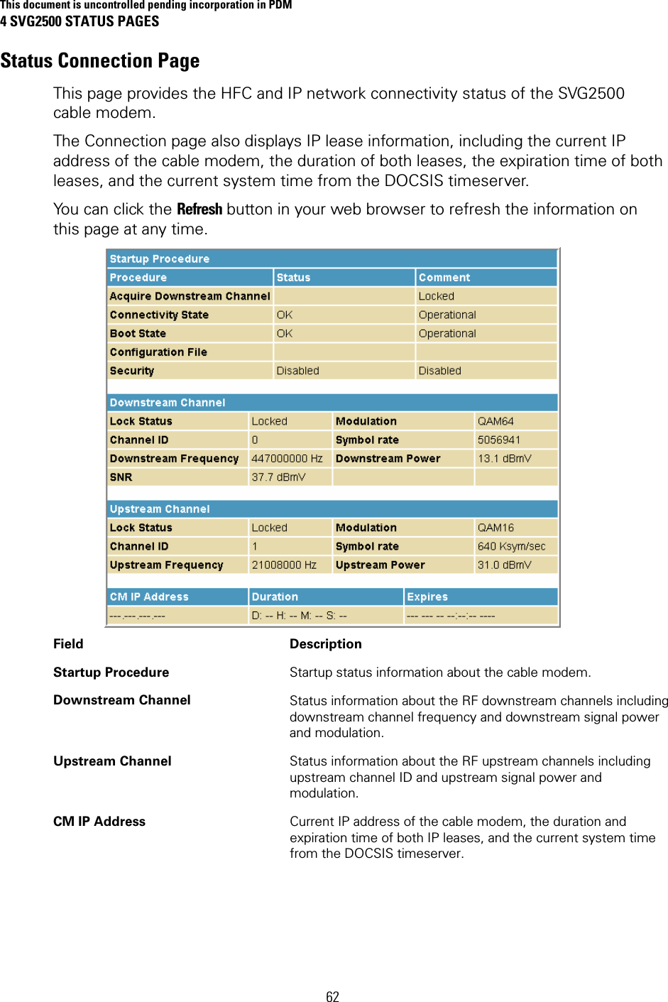
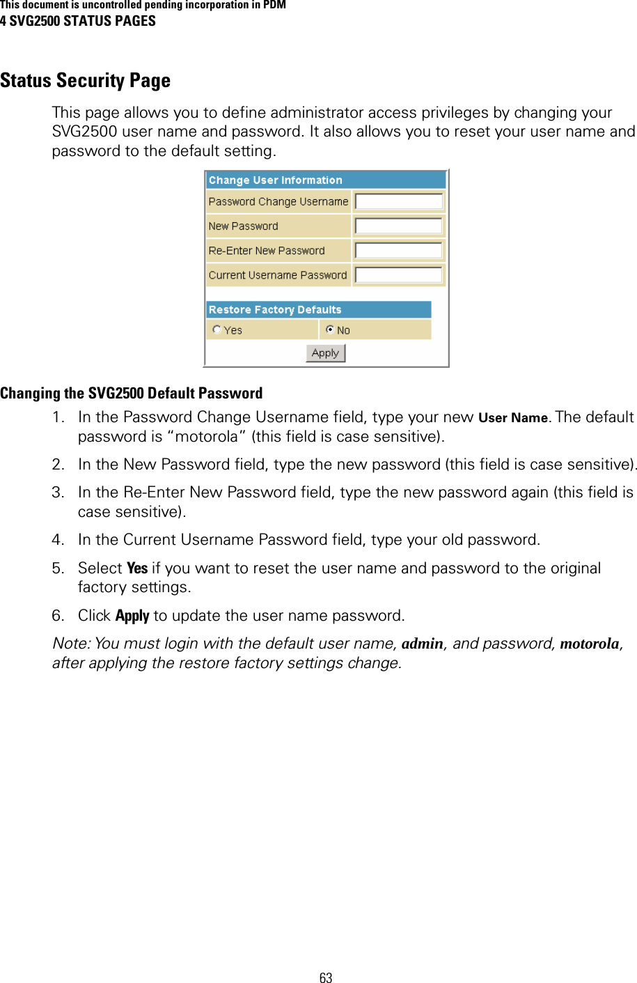
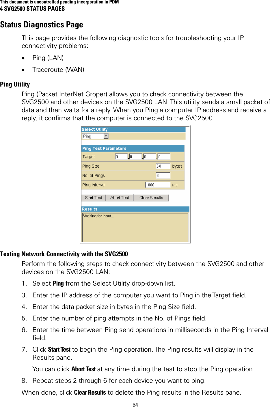
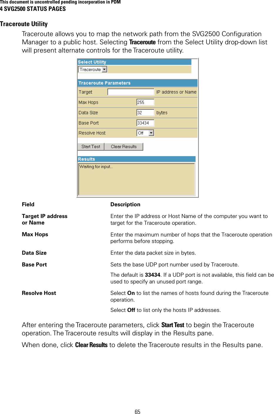
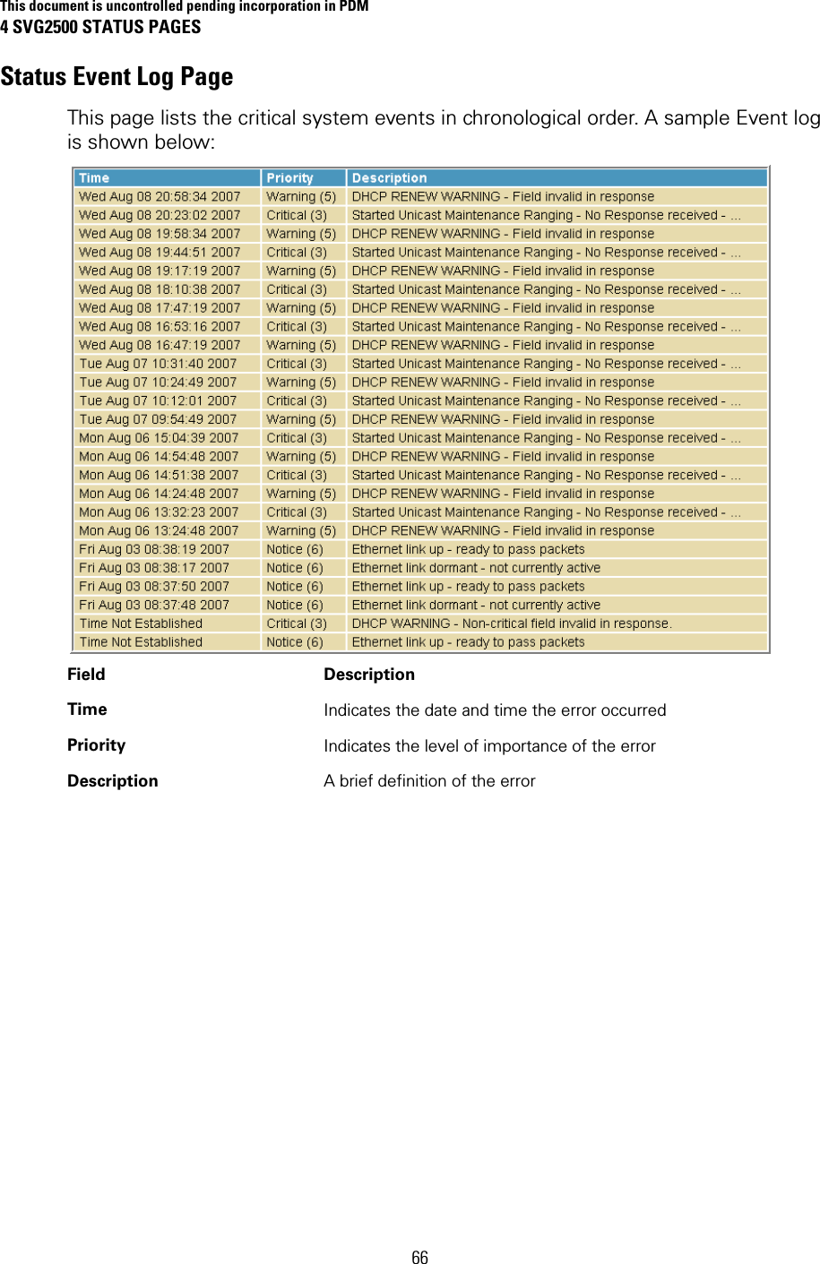
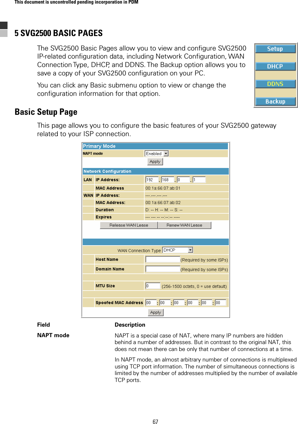
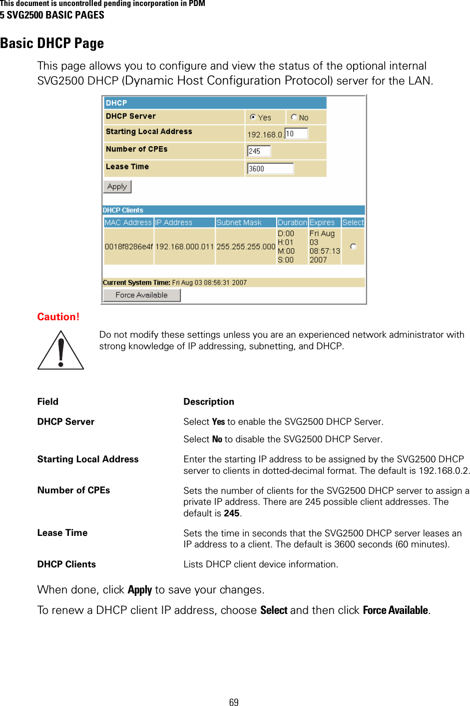
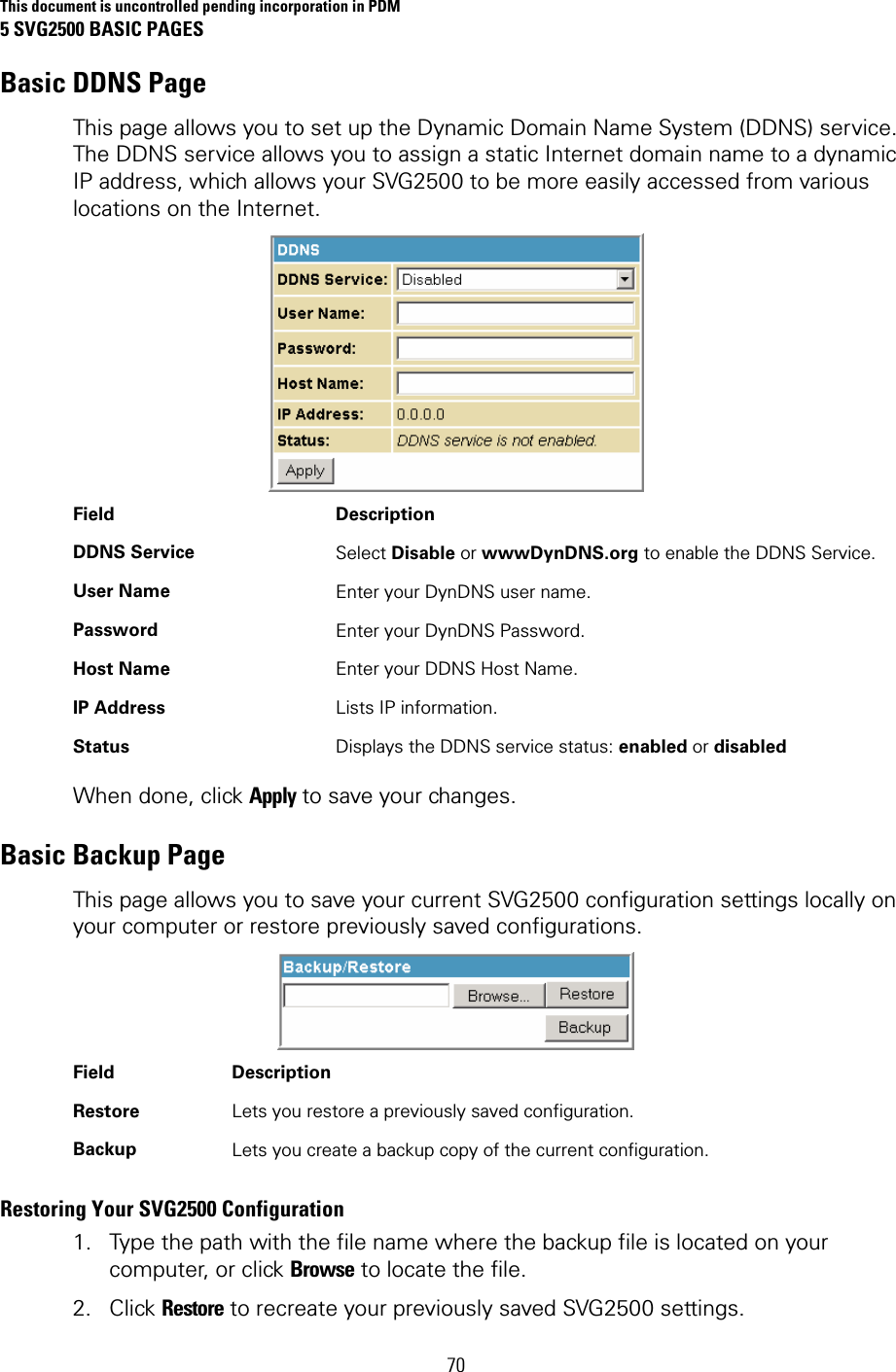
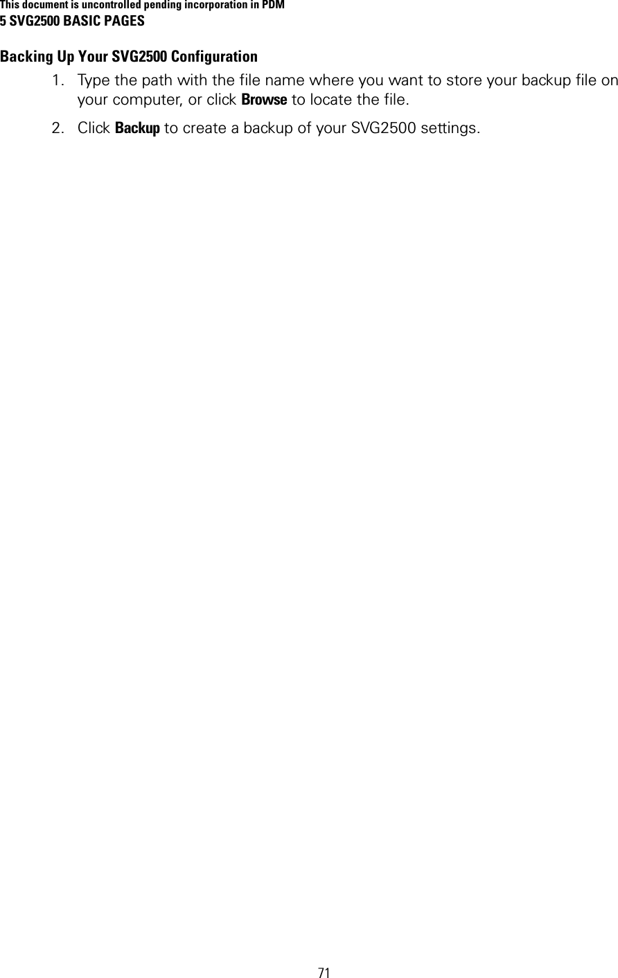
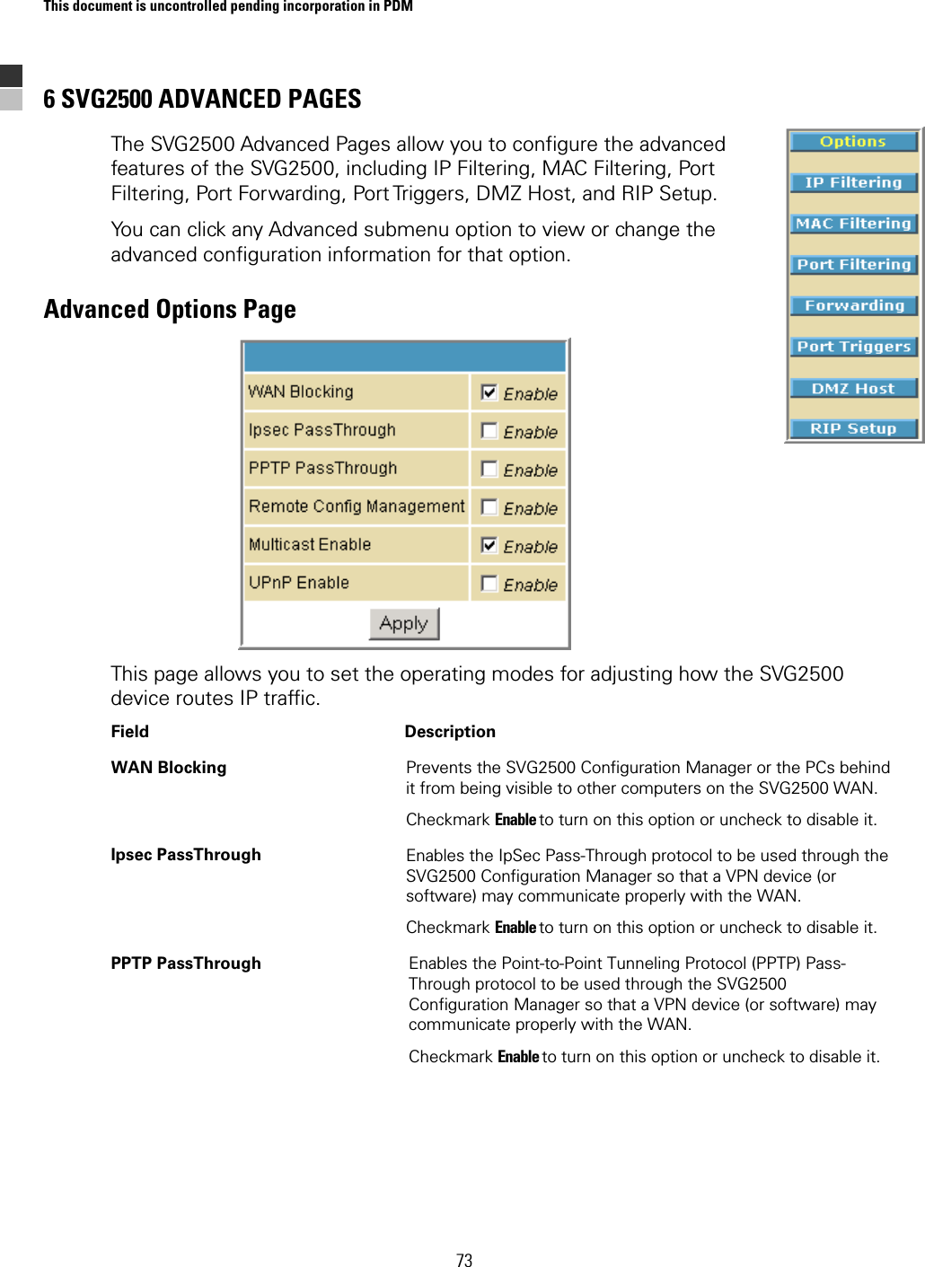
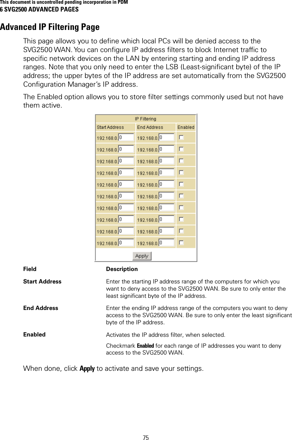
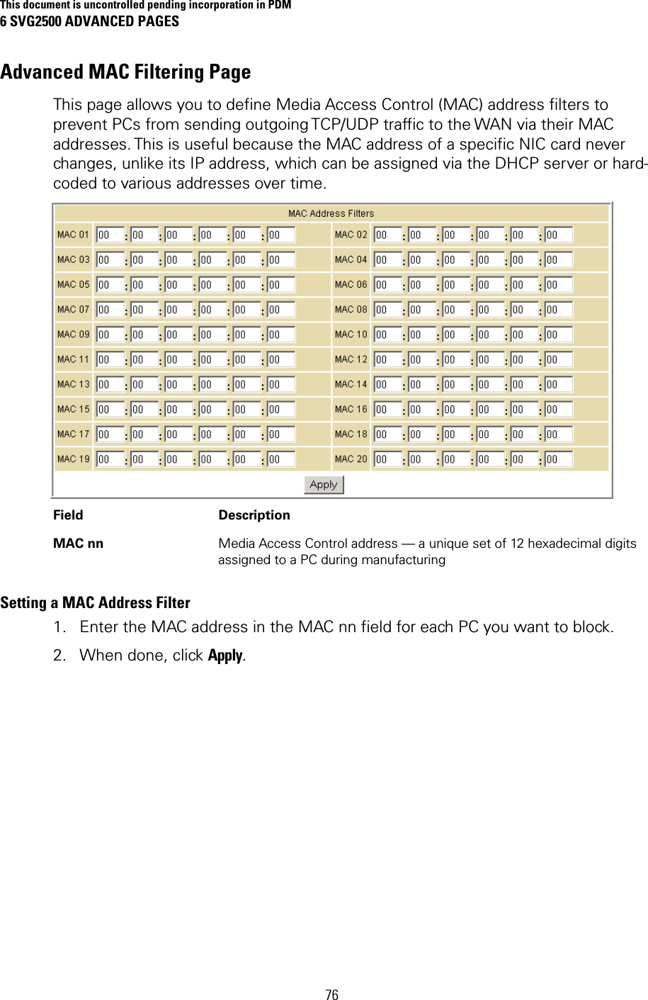
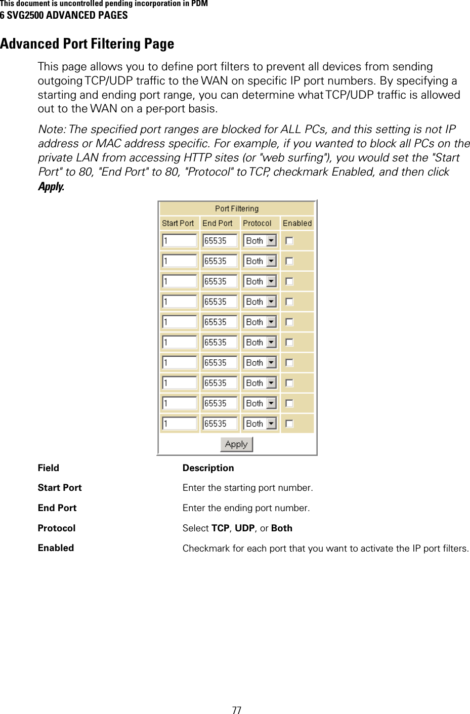
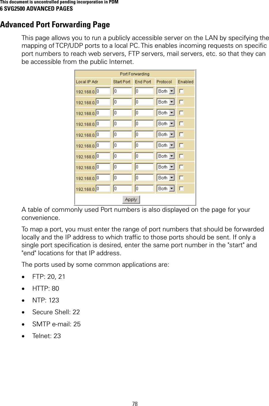
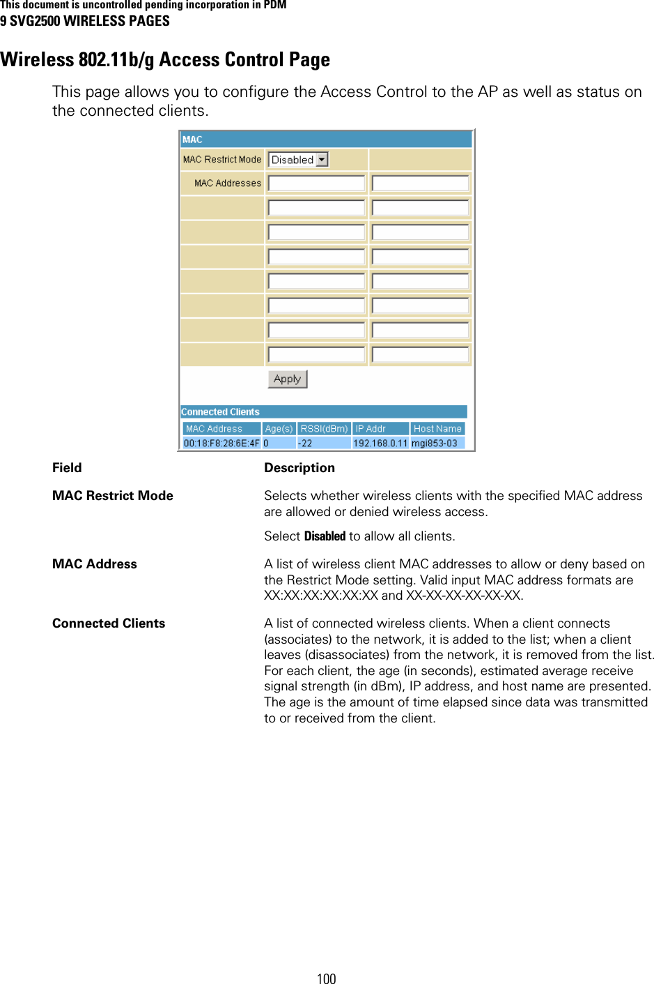
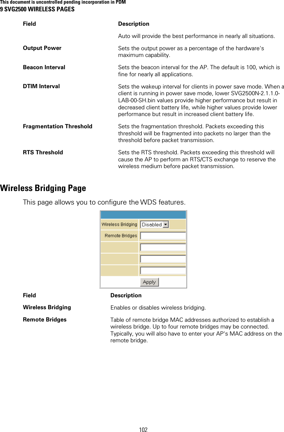
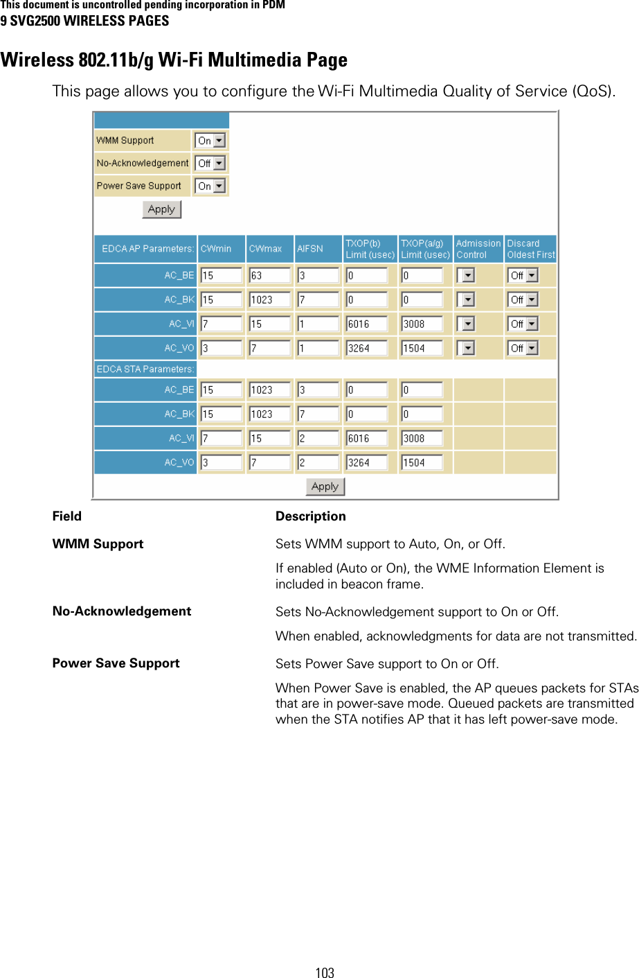
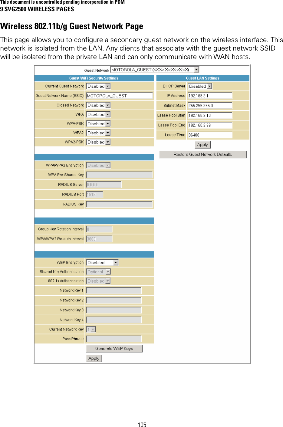
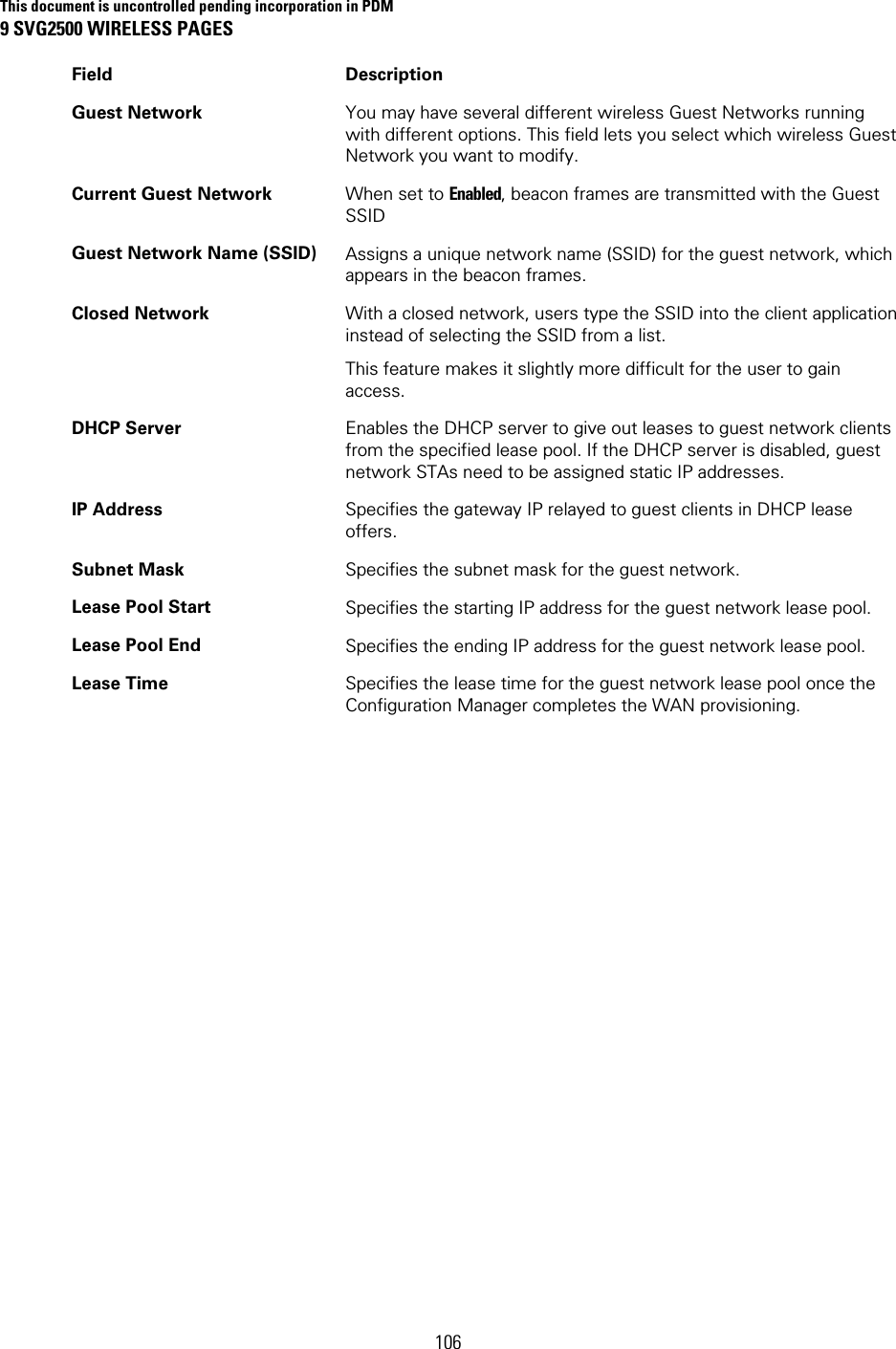
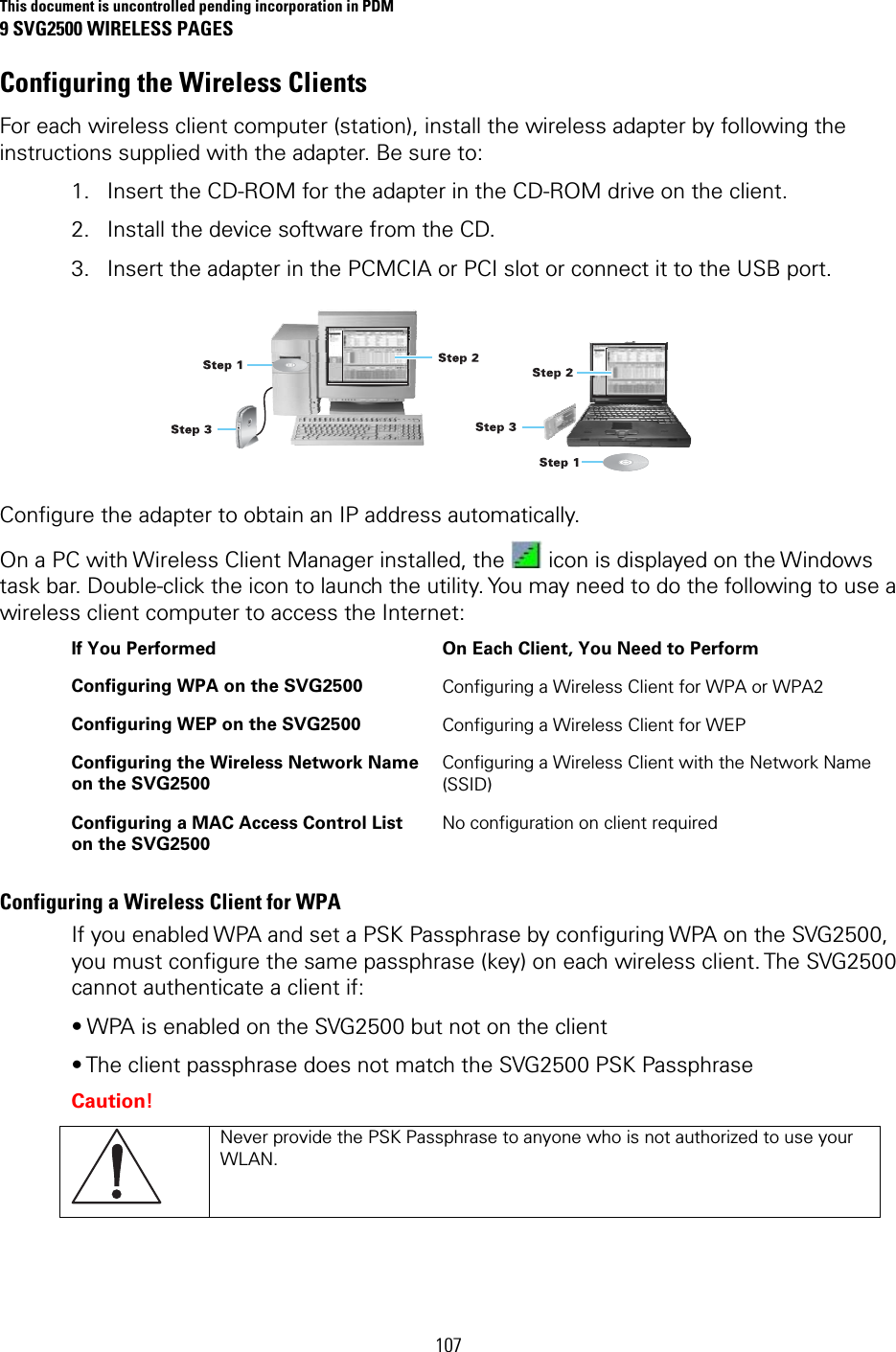
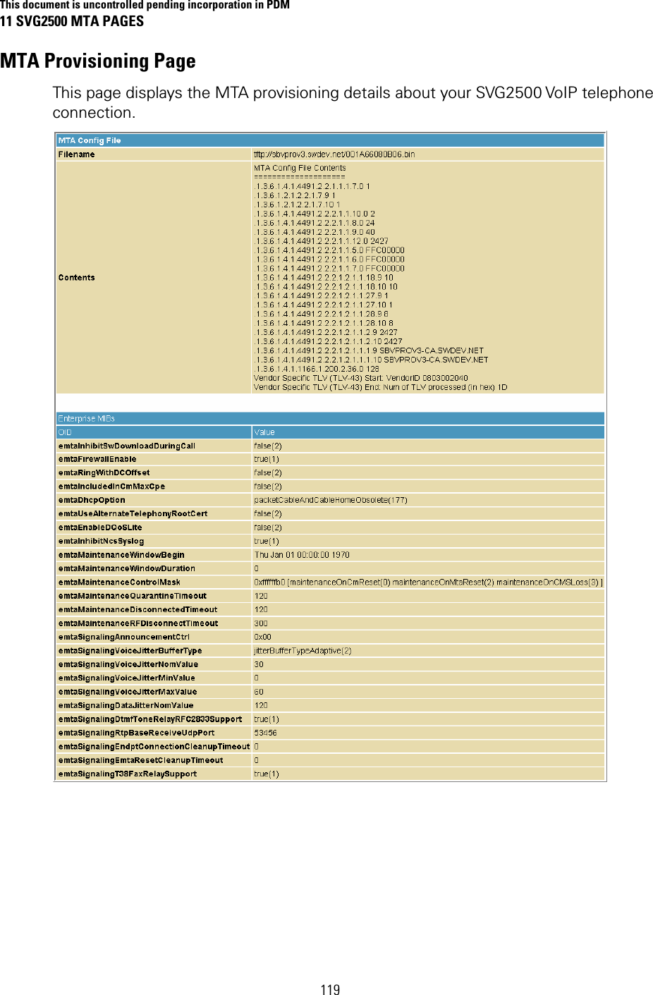
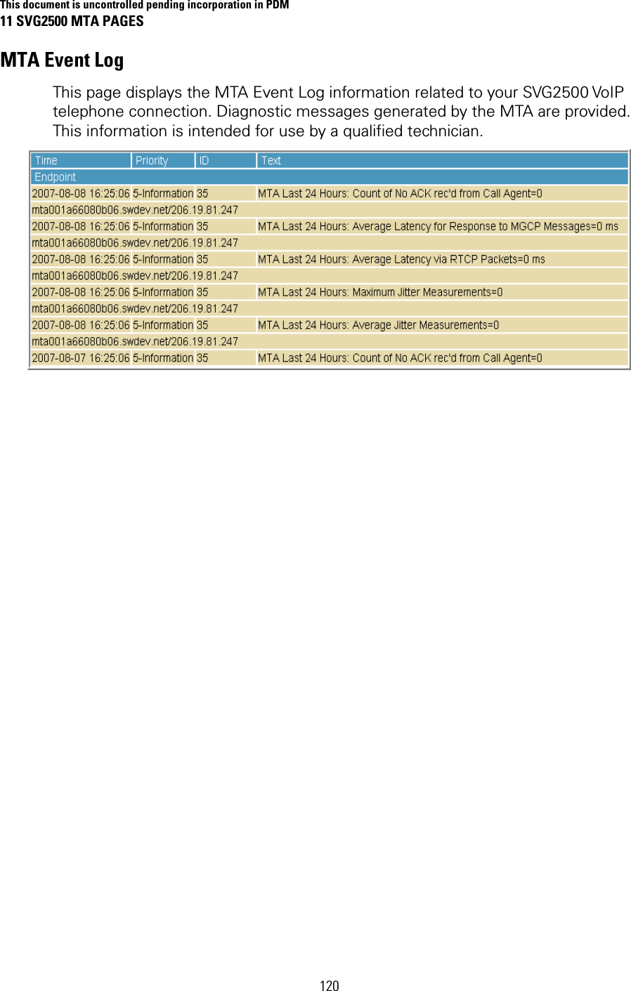
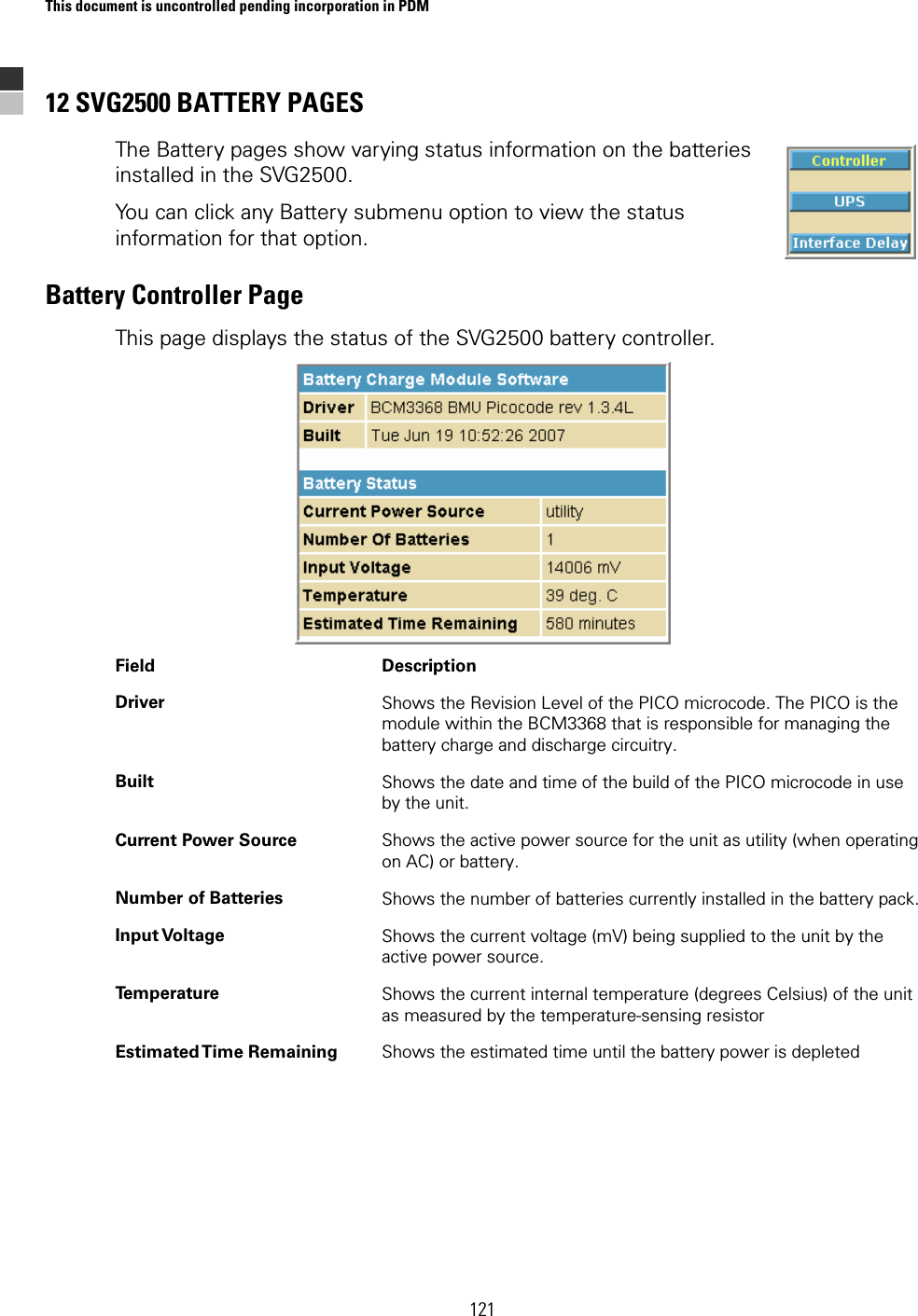
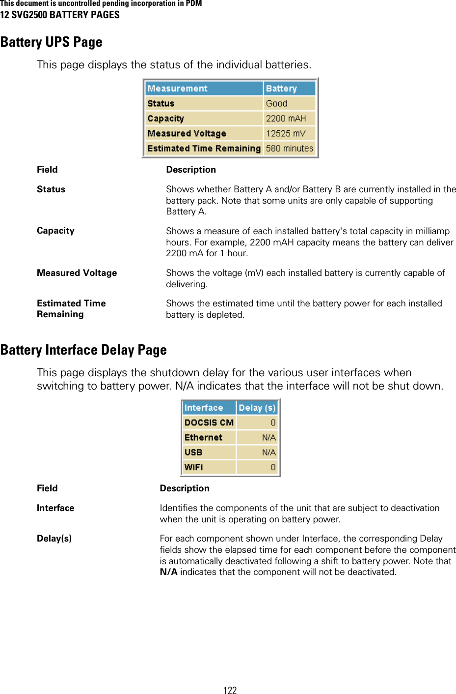
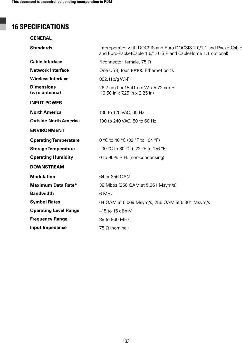
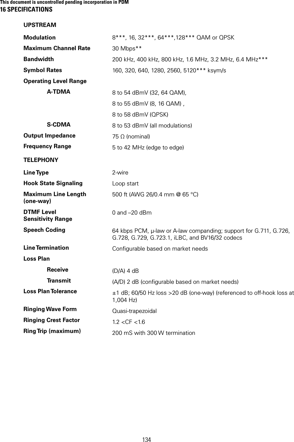
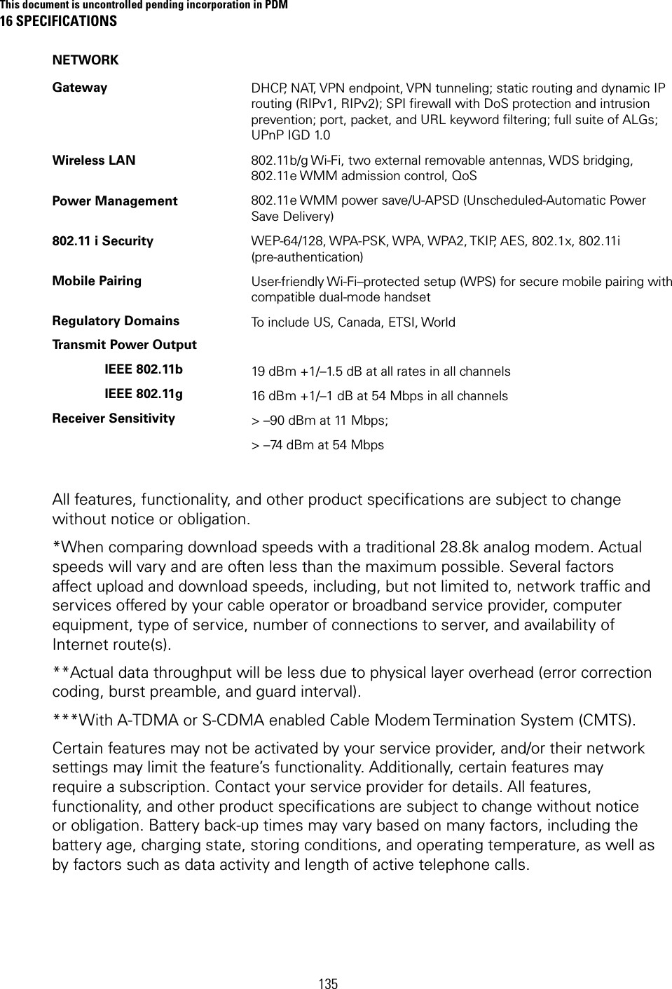
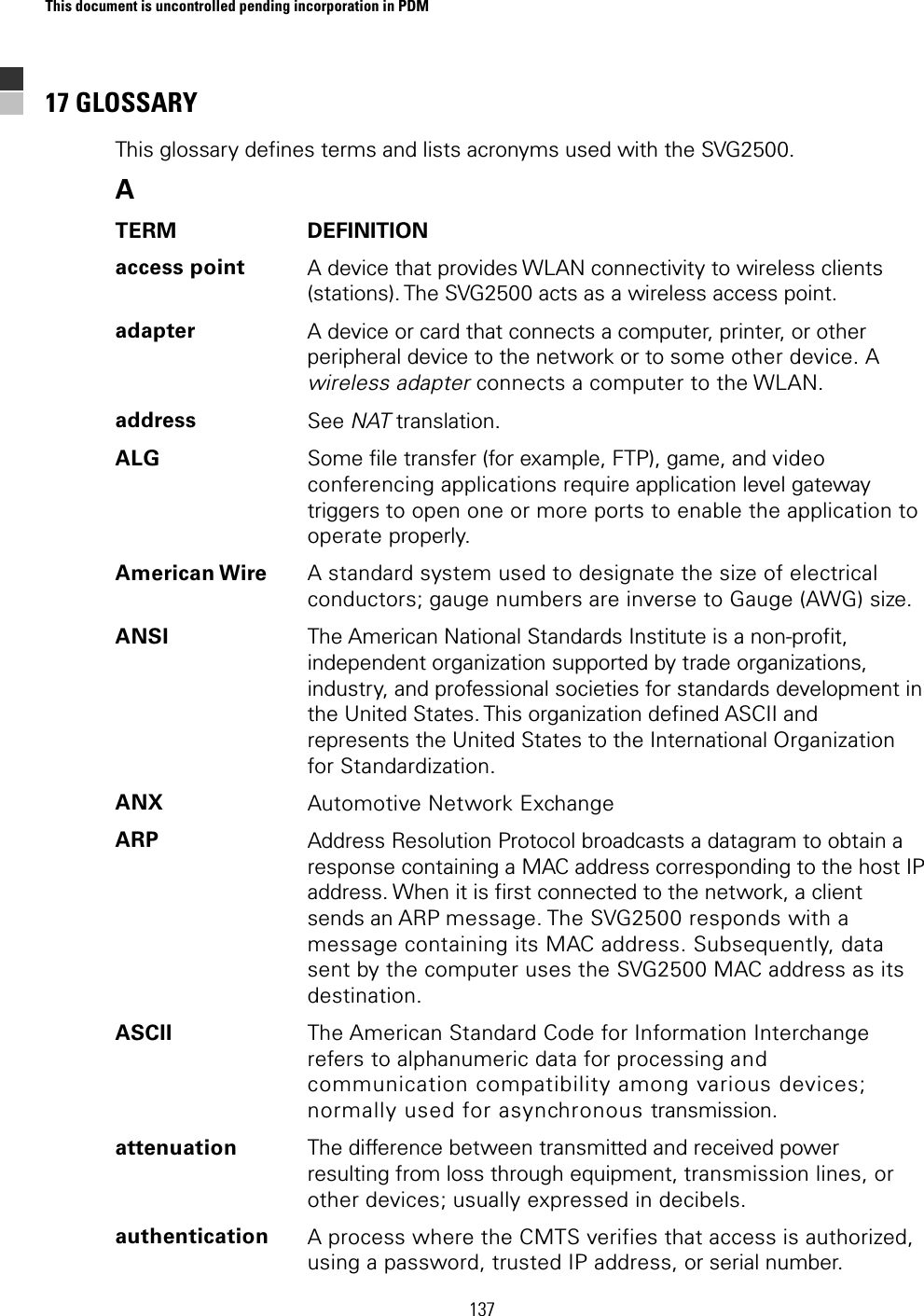
Manual Part 3