ARRIS SVG2500 SURFboard Voice Gateway User Manual SURFboard Wireless Voice Gateway
ARRIS Group, Inc. SURFboard Voice Gateway SURFboard Wireless Voice Gateway
ARRIS >
Contents
- 1. Manual Part 1
- 2. Manual Part 2
- 3. Manual Part 3
Manual Part 3
This document is uncontrolled pending incorporation in PDM
1 OVERVIEW
15
Security
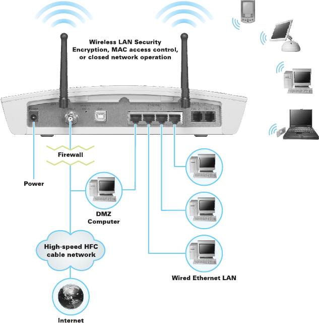
The SVG2500 provides the following:
• A firewall to protect the SVG2500 LAN from undesired attacks over the Internet
• For wireless transmissions, data encryption and network access control
Network Address Translation (NAT) provides some security because the IP
addresses of SVG2500 LAN computers are not visible on the Internet.
This diagram does not necessarily correspond to the network cabling. A full
discussion of network security is beyond the scope of this document.
Figure 1-6 — SVG2500 Security Measures
This document is uncontrolled pending incorporation in PDM
1 OVERVIEW
16
Firewall
The SVG2500 firewall protects the SVG2500 LAN from undesired attacks and other
intrusions from the Internet. It provides an advanced, integrated stateful-inspection
firewall supporting intrusion detection, session tracking, and denial-of-service attack
prevention. The firewall:
• Maintains state data for every TCP/IP session on the OSI network and transport
layers
• Monitors all incoming and outgoing packets, applies the firewall policy to each
one, and screens for improper packets and intrusion attempts
• Provides comprehensive logging for all:
• User authentications
• Rejected internal and external connection requests
• Session creation and termination
• Outside attacks (intrusion detection)
You can configure the firewall filters to set rules for port usage. For information about
choosing a predefined firewall policy template, see Section 7, SVG2500 Firewall
Pages.
DMZ
A de-militarized zone (DMZ) is one or more computers logically located outside the
firewall between an SVG2500 LAN and the Internet. A DMZ prevents direct access
by outside users to private data.
For example, you can set up a web server on a DMZ computer to enable outside
users to access your website without exposing confidential data on your network.
A DMZ can also be useful to play interactive games that may have a problem running
through a firewall. You can leave a computer used for gaming only exposed to the
Internet while protecting the rest of your network. For more information, see Gaming
Configuration Guidelines.
Port Triggering
When you run an application that accesses the Internet, it typically initiates
communications with a computer on the Internet. For some applications, especially
gaming, the computer on the Internet also initiates communications with your
computer. Because NAT does not normally allow these incoming connections:
• The SVG2500 has preconfigured port triggers for common applications.
• If needed, you can configure additional port triggers on the Advanced Port
Triggers Page.
This document is uncontrolled pending incorporation in PDM
1 OVERVIEW
17
Wireless Security
Because WLAN data is transmitted using radio signals, it may be possible for an
unauthorized person to access your WLAN unless you prevent them from doing so.
To prevent unauthorized eavesdropping of data transmitted over your LAN, you must
enable wireless security. The default SVG2500 settings neither provide security for
transmitted data nor protect network data from unauthorized intrusions.
The SVG2500 provides the following wireless security measures, which are
described in Section 9, SVG2500 Wireless Pages.
To prevent unauthorized eavesdropping, you must encrypt data transmitted over the
wireless interface using one of the following:
• If all of your wireless clients support Wi-Fi® Protected Access (WPA) encryption,
Motorola recommends using WPA. Otherwise, configure a Wired Equivalency
Privacy (WEP) key on the SVG2500 and each WLAN client.
• To protect LAN data from unauthorized intrusions, you can restrict WLAN access
to computers having one or both of:
• Known MAC addresses
• The same unique network name (SSID) as the SVG2500
Restricting access to computers having the same network name is also called
“disabling SSID broadcasting” or “enabling closed network operation.”
Port Forwarding
The SVG2500 opens logical data ports when a computer on its LAN sends data,
such as e-mail messages or web data, to the Internet. A logical data port is different
from a physical port, such as an Ethernet port. Data from a protocol must go through
certain data ports.
Some applications, such as games and videoconferencing, require multiple data
ports. If you enable NAT, this can cause problems because NAT assumes that data
sent through one port will return to the same port. You may need to configure port
forwarding to run applications with special requirements.
To configure port forwarding, you must specify an inbound (source) port or range of
ports. The inbound port opens only when data is sent to the inbound port and closes
again after a specified time elapses with no data sent to it. You can configure up to
32 port forwarding entries using the Advanced Port Forwarding Page.
Virtual Private Networks
The SVG2500 supports multiple tunnel VPN pass-through operation to securely
connect remote computers over the Internet. The SVG2500:
• Is compatible with Point to Point Tunneling Protocol (PPTP) and Layer 2 Tunneling
Protocol (L2TP)
• Is fully interoperable with any IPSec client or gateway and ANX certified IPSec
stacks

This document is uncontrolled pending incorporation in PDM
19
2 INSTALLATION
The following topics provide information about installing the SVG2500 hardware:
• Before You Begin
• Precautions
• Signing Up for Service
• Computer System Requirements
• Installing the Battery
• Connecting the SVG2500 to the Cable System
• Cabling the LAN
• Installing USB Drivers
• Connecting a PC to the SVG2500 USB Port
• Obtaining an IP Address for Ethernet
• Configuring TCP/IP
• Installing the Telephone for VoIP
• Wall Mounting Your SVG2500
For information about WLAN setup, see Setting Up Your Wireless LAN.
Before You Begin
Before you begin the installation, check that the following items were included with
your Motorola SVG2500 Gateway:
Item Description
Power cord
Connects the SVG2500 to a power adapter that
connects to an AC electrical outlet
Telephone cable (RJ-11) Connects to a telephone outlet
Ethernet cable Connects to the Ethernet port
USB cable Connects to the USB port
SVG2500 Installation
CD-ROM
Contains this user guide and USB drivers
SVG2500 Quick
Installation Guide
Contains basic information for getting started with
the SVG2500
This document is uncontrolled pending incorporation in PDM
2 INSTALLATION
20
You must have the latest service packs and patches installed on your computer for
your operating system. You will need 75-ohm coaxial cable with F-type connectors to
connect the SVG2500 to the nearest cable outlet. If a TV is connected to the cable
outlet, you may need a 5 to 900 MHz RF splitter and two additional coaxial cables to
use both the TV and the SVG2500.
Determine the connection types you will make to the SVG2500. Check that you have
the required cables, adapters, and adapter software. You may need:
Wireless LAN Wireless adapter and driver software for each computer having a wireless
connection.
Wired Ethernet Ethernet cables and network interface cards (NICs) with accompanying
installation software
LAN To connect more than four computers to the SVG2500, one or more Ethernet
hubs or switches
USB A USB cable and the SVG2500 Installation CD-ROM containing the software
for USB installation
Coaxial cable, RF splitters, hubs, and switches are available at consumer electronic stores.
Precautions
Postpone SVG2500 installation until there is no risk of thunderstorm or lightning
activity in the area.
To avoid potential shock, always unplug the power cord from the wall outlet or other
power source before disconnecting it from the SVG2500 rear panel.
To prevent overheating the SVG2500, do not block the ventilation holes on the sides
of the unit. Do not open the unit. Refer all service to your Internet Service provider.
Wipe the unit with a clean, dry cloth. Never use cleaning fluid or similar chemicals.
Do not spray cleaners directly on the unit or use forced air to remove dust.
This document is uncontrolled pending incorporation in PDM
2 INSTALLATION
21
Signing Up for Service
You must sign up with an Internet Service provider to access the Internet and other
online services. To activate your service, call your local Internet Service provider.
You need to provide the MAC address marked HFC MAC ID printed on the Bottom
Label on the SVG2500. You can record it in the SVG2500 Quick Installation Guide.
You should ask your Internet Service provider the following questions:
• Do you have any special system requirements?
• When can I begin to use my SVG2500?
• Are there any files I need to download after connecting the SVG2500?
• Do I need a user name or password to access the Internet or use e-mail?
Computer System Requirements
You can connect Microsoft Windows, Macintosh, UNIX®, or Linux® computers to the
SVG2500 LAN using one of the following:
• Ethernet — 10Base-T or 10/100Base-T Ethernet adapter with proper driver
software installed.
• Wireless — Any IEEE 802.11g or IEEE 802.11b device. This includes any Wi-Fi
certified wireless device, such as a cellular telephone equipped with this feature.
In addition, your computer must meet the following requirements:
• PC with Pentium class or better processor
• Windows® 2000, Windows® XP, Windows VistaTM, Macintosh, or Linux®
operating system with operating system CD-ROM available
• Minimum 16 MB RAM recommended
• 10 MB available hard disk space
You can use any web browser such as Microsoft® Internet Explorer, Netscape
Navigator®, or Mozilla® Firefox® with the SVG2500.
The following operating systems are not supported by the SVG2500. Microsoft
support for these products has ended:
• Windows® 95
• Windows® 98
• Windows® 98 SE
• Windows® Me
• Windows NT®
Note: UNIX, Linux, or Macintosh computers only use the Ethernet connection.
This document is uncontrolled pending incorporation in PDM
2 INSTALLATION
22
You can use the USB connection with any PC running Windows 2000, Windows XP,
or Windows Vista that has a USB interface. The USB connection requires special
USB driver software that is supplied on the SVG2500 Installation CD-ROM. You can
upgrade your USB drivers from the Motorola Downloads page:
http://broadband.motorola.com/consumers/support/default.asp
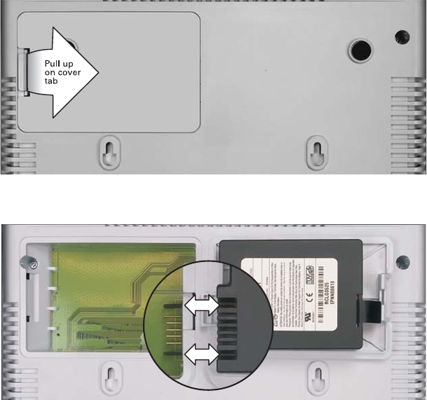
Installing the Battery
Before you begin the installation, you must first install the battery in your SVG2500.
Please read Safety Requirements for the SVG2500 Lithium-Ion Battery before
proceeding.
1. Place the SVG2500 on a soft surface to access the bottom of the unit.
2. Pull up on the battery cover tab.
3. Align the key pins in the SVG2500 with the key slots on the battery for proper
contact.
This document is uncontrolled pending incorporation in PDM
2 INSTALLATION
23
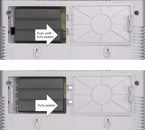
4. The battery connectors should mate with the connectors on the SVG2500. Make
sure the pull-tab is accessible and does not prevent the battery cover from
closing properly.
5. Reinstall the battery cover with the alignment tabs seated downward.
It may take up to 12 hours for the battery to reach full charge when:
• It is installed for the first time.
• It is replaced.
• It is fully discharged.
Battery back-up times may vary based on many factors, including the battery age,
charging state, storing conditions, and operating temperature, as well as by factors
such as data activity and length of active telephone calls.
This document is uncontrolled pending incorporation in PDM
2 INSTALLATION
24
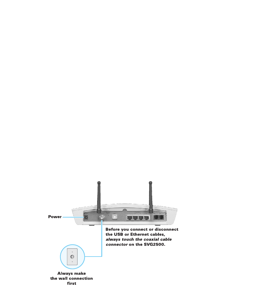
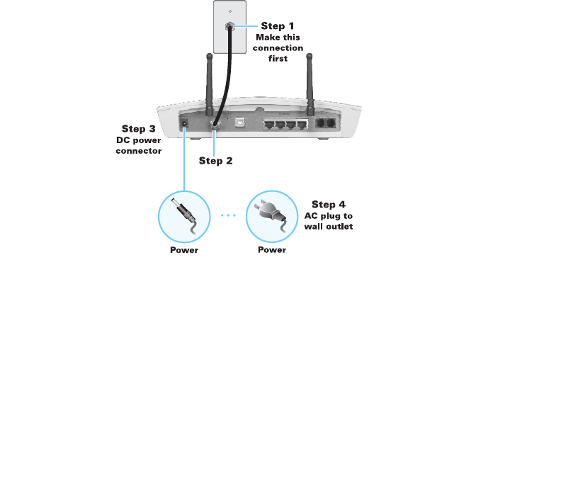
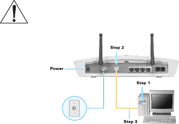
Connecting the SVG2500 to the Cable System
Before starting, be sure the computer is turned on and the SVG2500 is unplugged.
1. Connect one end of the coaxial cable to the cable outlet or splitter.
2. Connect the other end of the coaxial cable to the cable connector on the
SVG2500. Hand-tighten the connectors to avoid damaging them.
3. Plug the power cord into the power connector on the SVG2500.
4. Plug the power cord into the electrical outlet. This turns the SVG2500 on. You do
not need to unplug it when not in use. The first time you plug in the SVG2500,
allow it 5 to 30 minutes to find and lock on the appropriate communications
channels.
5. Check that the lights on the front panel cycle through this sequence:
POWER Turns on when AC power is connected to the SVG2500.
Indicates that the power is connected properly.
ONLINE Flashes during SVG2500 registration and configuration.
Changes to solid green when the SVG2500 is registered.
DS Flashes while scanning for the downstream receive channel.
Changes to solid green when the receive channel is locked.
US Flashes while scanning for the upstream send channel.
Changes to solid green when the send channel is locked.

This document is uncontrolled pending incorporation in PDM
2 INSTALLATION
25
Cabling the LAN
After connecting to the cable system, you can connect your wired Ethernet LAN.
Some samples are shown in Wired Ethernet LAN. On each networked computer, you
must install proper drivers for the Ethernet adapter. Detailed information about
network cabling is beyond the scope of this document.
Installing USB Drivers
This section describes installing the USB driver on a PC connected to the USB port
on the SVG2500. Before connecting the PC to the SVG2500 USB port, perform one
of the following procedures applicable to the Windows version you are running:
• Installing the Windows 2000 USB Driver
• Installing the Windows XP USB Driver
• Installing the Windows Vista USB Driver
The SVG2500 USB driver does not support Macintosh or UNIX computers. For those
systems, you can connect through Ethernet only.
Caution!
Be sure the SVG2500 Installation CD-ROM is inserted in the CD-ROM drive
before you plug in the USB cable.
If you have a problem installing the USB driver, remove it by performing one of the
following procedures applicable to the Windows version you are running:
• Removing the Windows 2000 USB Driver
• Removing the Windows XP USB Driver
When done, run the Motorola USB Driver Removal Utility.
This document is uncontrolled pending incorporation in PDM
2 INSTALLATION
26
Installing the Windows 2000 USB Driver
1. Insert the SVG2500 Installation CD-ROM in the CD-ROM drive. This CD contains
the USB drivers and must be inserted and read by the PC before you connect the
SVG2500 to the PC.
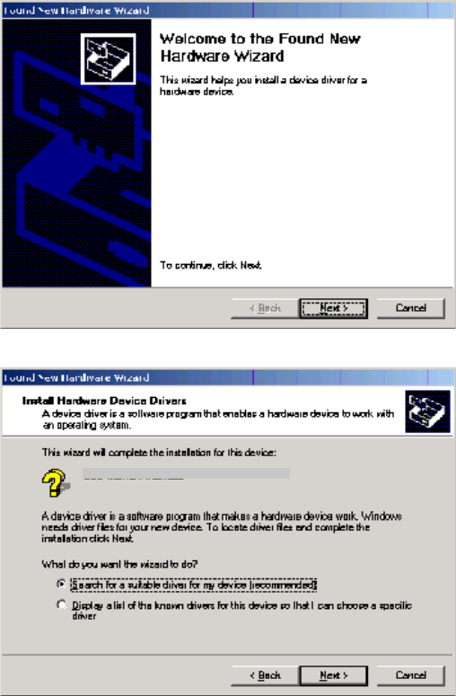
2. Connect the USB cable as shown in USB Connection. A few seconds after you
complete the USB connection, the Found New Hardware window is displayed.
3. Click Next to display the Install Hardware Device Drivers window.
4. Be sure Search for a suitable driver for my device is selected.
Motorola SURFboard SVG USB Gaeway
This document is uncontrolled pending incorporation in PDM
2 INSTALLATION
27
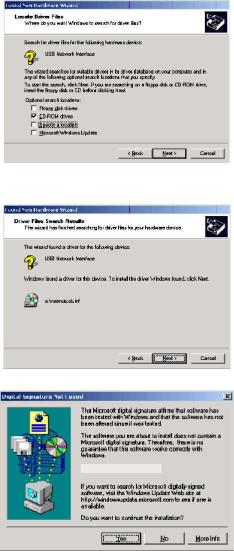
5. Click Next to display the Locate Driver Files window.
6. Checkmark CD-ROM drives only.
7. Click Next to display the Driver Files Search Results window.
8. Click Next to display the Digital Signature Not Found window.
Motorola USB SVG Modem
This document is uncontrolled pending incorporation in PDM
2 INSTALLATION
28
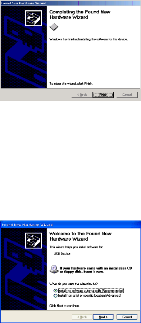
9. Click Yes to continue the installation. The Found New Hardware Wizard window is
displayed.
10. Click Finish to complete the installation.
When you finish setting up the USB driver, you can continue with Configuring TCP/IP.
If you have any difficulties setting up the USB driver, perform Removing the USB
Driver in Windows 2000 and repeat the setup procedure.
Installing the Windows XP USB Driver
1. Insert the SVG2500 Installation CD-ROM in the CD-ROM drive. This CD contains
the USB drivers and must be inserted and read by the PC before you connect the
SVG2500 to the PC.
2. Connect the USB cable as shown in USB Connection.
A few seconds after you complete the USB connection, the Found New
Hardware Wizard window is displayed.
3. Be sure Install the software automatically is selected.
Motorola USB SVG Modem
This document is uncontrolled pending incorporation in PDM
2 INSTALLATION
29
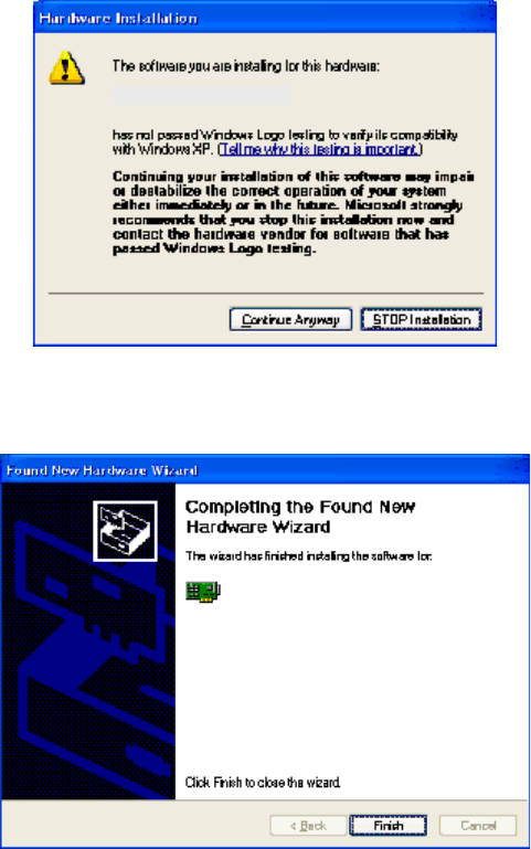
4. Click Next to display the Hardware Installation window.
5. Click Continue Anyway. Windows automatically searches for the correct USB drivers
and installs them. If the installation is successful, the Found New Hardware
Wizard window is displayed:
Although your SVG model number may be different than in the images in this
guide, the procedure is the same.
6. Click Finish to complete the installation. Otherwise, be sure the SVG2500
Installation CD-ROM is correctly seated in the CD-ROM drive.
When you finish setting up the USB driver, you can continue with Configuring TCP/IP.
Motorola USB SVG Modem
Motorola USB SVG Modem
This document is uncontrolled pending incorporation in PDM
2 INSTALLATION
30
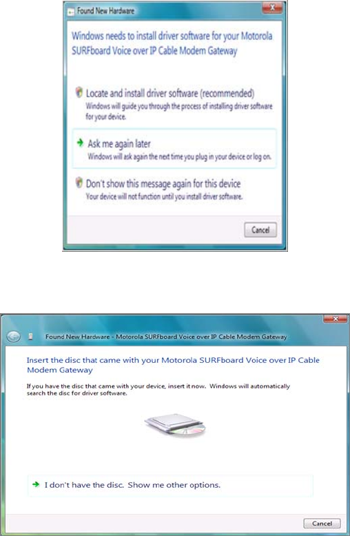
Installing the Windows Vista USB Driver
1. Be sure the USB cable is connected to both the computer and the SVG2500
gateway. If not, connect it as described in Connecting a PC to the USB Port.
A few seconds after you complete the USB connection, the Found New
Hardware window is displayed.
2. Click Locate and install driver software. The Vista permissions pop up appears.
3. Click Continue to proceed. The Found New Hardware window is displayed.
This document is uncontrolled pending incorporation in PDM
2 INSTALLATION
31
4. Insert the SVG2500 Installation CD containing the USB drivers in the CD-ROM
drive. This CD must be inserted and read by the PC before you connect the
SVG2500 to the PC.
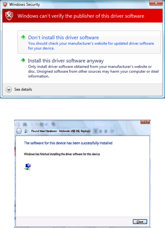
Windows automatically searches the CD for driver software. The Windows
Security window is displayed.
5. Click Install this driver software anyway. The Found New Hardware window is
displayed.
6. Click Close. The SVG2500 USB interface is now installed and ready for operation.
When you finish installing the USB driver, you can continue with Configuring TCP/IP.
Motorola USB SVG Modem
This document is uncontrolled pending incorporation in PDM
2 INSTALLATION
32
Connecting a PC to the SVG2500 USB Port
You can connect a single PC running Windows 2000, Windows XP, or Windows Vista
to the SVG2500 USB port.
Caution!
Before plugging in the USB cable, be sure the SVG2500 Installation CD-ROM is inserted in the
PC CD-ROM drive.
To connect a PC to the SVG2500 USB port:
1. Insert the SVG2500 Installation CD-ROM in the CD-ROM drive to install the USB
driver. See Installing USB Drivers for the applicable procedure for the Windows
version you are running.
2. Connect the USB cable to the USB port on the back of the SVG2500.
3. Connect the other end of the USB cable to the USB port on the computer.
Obtaining an IP Address for an Ethernet Connection
You can use either of the following two options to obtain the IP address for the
network interface on your computer:
• Retrieve the statically defined IP address and DNS address
• Automatically retrieve the IP address using the Network DHCP server
The Motorola SVG2500 gateway provides a DHCP server on its LAN. It is
recommended that you configure your LAN to obtain the IPs for the LAN and DNS
server automatically.
This document is uncontrolled pending incorporation in PDM
2 INSTALLATION
33
Windows 2000 or Windows XP
To retrieve the IP and DNS addresses, do the following on each Ethernet client
computer running Windows 2000 or Windows XP:
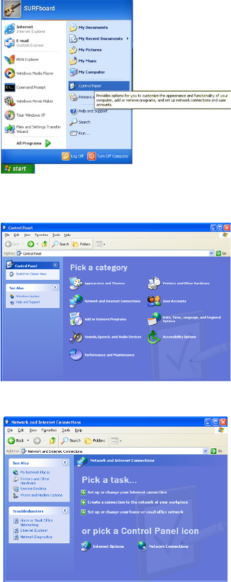
1. From the Windows Desktop, select Control Panel to display the Control Panel
window.
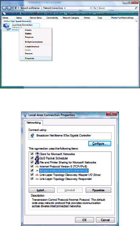
2. Select Network Connections to display the Network Connections window.
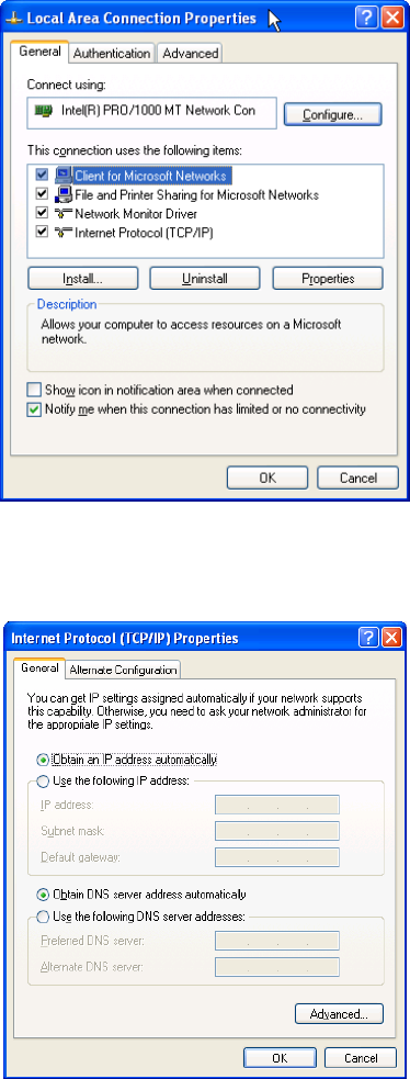
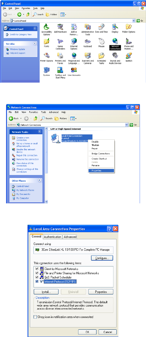
3. Right-click the Ethernet connection icon and select Properties to display the Local
Area Connection Properties window:
4. Under the General tab, select (or highlight) Internet Protocol (TCP/IP) and then
click Properties button.
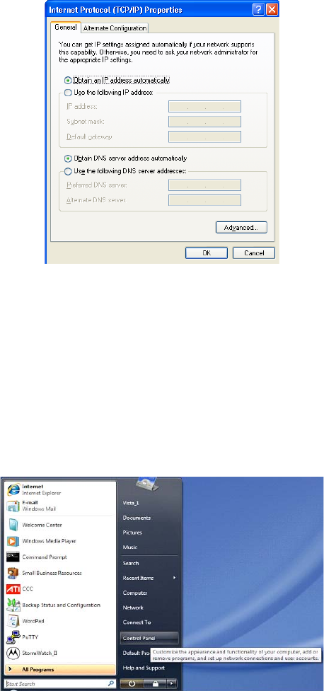
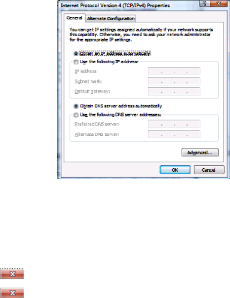
The Internet Protocol (TCP/IP) Properties window is displayed:

This document is uncontrolled pending incorporation in PDM
2 INSTALLATION
34
5. Select the Obtain an IP address automatically radio button.
6. Select the Obtain DNS server address automatically radio button.
7. Click OK twice to save the IP settings.
8. Exit the Control Panel.
To automatically retrieve the IP Address, do the following on each Ethernet client
computer running Windows 2000 or Windows XP:
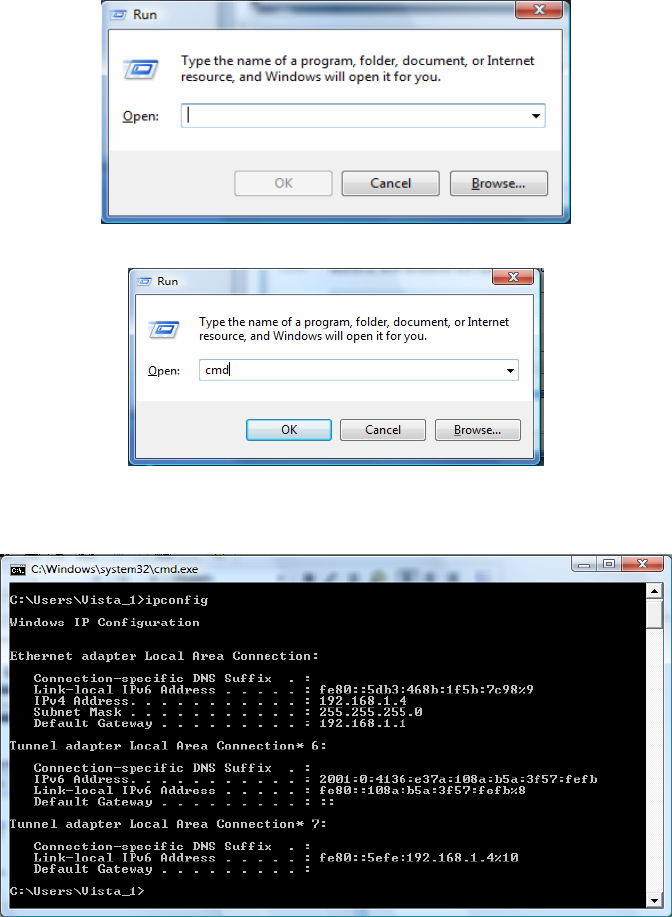
1. From the Windows Desktop, click Start to display the Windows Start menu.
2. Select Run to display the Run window.
3. Type cmd in the Open entry box and then click OK to display a command prompt
window.
4. Type ipconfig /renew and press Enter to obtain your computer’s IP address from
the DHCP server on the Motorola SVG2500.
5. Type exit and press Enter to return to Windows.
Windows Vista
To retrieve the IP and DNS addresses, do the following on each Ethernet client
computer running Windows Vista:
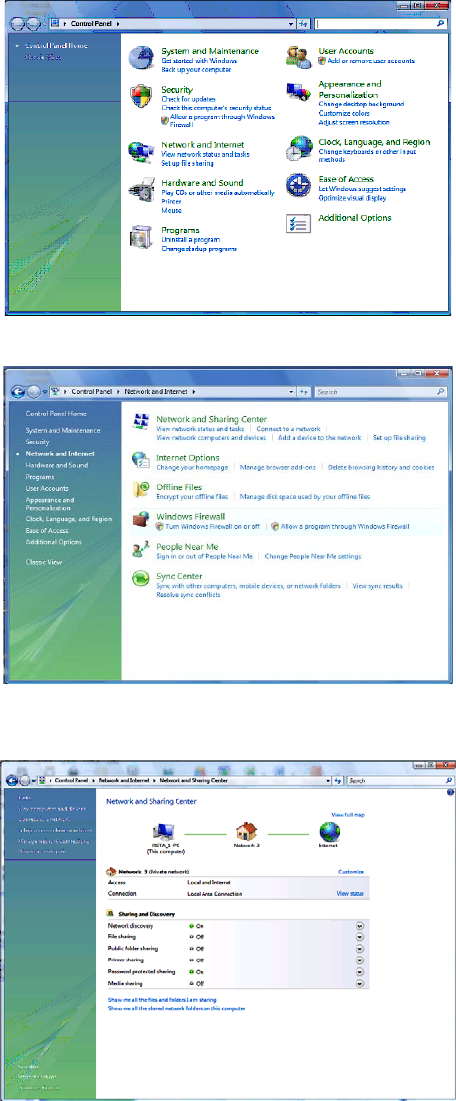
1. From the Windows Desktop, select Control Panel to display the Control Panel
Home window.
2. Click Network and Internet to display the Network and Internet window.
3. Click Network and Sharing Center to display the Network and Sharing Center window.
4. Click Manage network connections to display the LAN or High-speed Internet
connections window.
5. Right-click the network connection icon and select Properties from the drop-down
menu to display the Local Area Connection Properties window.
Note: If more than one network connection is displayed, Be sure to select your
network interface connection.
Windows Vista may prompt you to allow access to the Network Properties
Options. If you see the message User Account Control - Windows needs your
permission to continue, select Continue.
6. Select Internet Protocol Version 4 (TCP/IPv4) and click Properties to display the Internet
Protocol Version 4 (TCP/IPv4) Properties window.
7. Select the Obtain an IP address automatically radio button.
8. Select the Obtain DNS server address automatically radio button.
9. Click OK twice to close both network properties windows.
10. Click at the top right corner of each network window to close it.
11. Click to exit the Control Panel and save the IP settings.
This document is uncontrolled pending incorporation in PDM
2 INSTALLATION
35
Linux
To retrieve the IP Address, do the following on each client computer running Linux:
1. Type su at the system prompt to log in as super-user.
2. Type ifconfig to display the network devices and allocated IP addresses.
3. Type pump -i <dev>.
where <dev> is the network device name
4. Type ifconfig again to view the new allocated IP address.
5. Check to make sure no firewall is active on the device <dev>.
Macintosh or UNIX
Follow the instructions in the applicable user documentation.
Configuring TCP/IP
Make sure all client computers are configured for TCP/IP which is a protocol for
communication between computers. Perform one of the following for the operating
system you are running:
• Configuring TCP/IP in Windows 2000
• Configuring TCP/IP in Windows XP
• Configuring TCP/IP in Windows Vista
• For Macintosh or UNIX systems, follow the instructions in the applicable
Macintosh or UNIX user documentation.
After configuring TCP/IP on your computer, you must verify the IP address. Perform
one of the following:
• Verifying the IP Address in Windows 2000 or Windows XP
• Verifying the IP Address in Windows Vista
• For Macintosh or UNIX systems, follow the instructions in the applicable
Macintosh or UNIX user documentation.
This document is uncontrolled pending incorporation in PDM
2 INSTALLATION
36
Configuring TCP/IP in Windows 2000
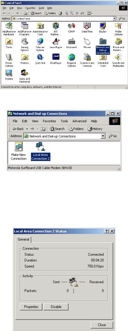
1. Select Control Panel from either the Windows Start menu or Windows
Desktop to display the Control Panel window.
2. Double-click Network and Dial-up Connections to display the Network and
Dial-up Connections window.
In the steps that follow, a connection number such as 1, 2, or 3 represents
PCs with multiple network interfaces. PCs having only one network interface
may be represented as “Local Area Connection.”
3. Double-click Local Area Connection number to display the Local Area
Connection number Status window. The value of number varies from system
to system.
This document is uncontrolled pending incorporation in PDM
2 INSTALLATION
37
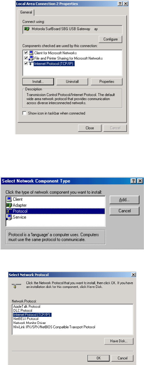
4. Click Properties to display the Local Area Connection number Properties
window. Information similar to the following displays.
5. If Internet Protocol (TCP/IP) is in the list of components, TCP/IP is installed.
You can skip to step 8.
6. If Internet Protocol (TCP/IP) is not in the list of components, click Install. The
Select Network Component Type window displays:
7. Click Protocol and then click Add. The Select Network Protocol window
displays:
This document is uncontrolled pending incorporation in PDM
2 INSTALLATION
38
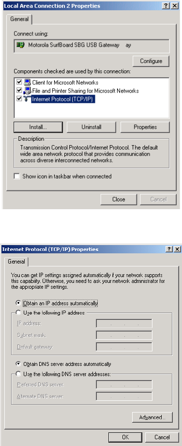
8. Click Internet Protocol (TCP/IP) and then click OK. The Local Area Connection
number Properties window redisplays.
9. Click Internet Protocol (TCP/IP) and then click Properties to display the Internet
Protocol (TCP/IP) Properties window:
10. Be sure Obtain an IP address automatically and Obtain DNS server address automatically
are selected.
11. Click OK to save the TCP/IP settings and exit the TCP/IP Properties window.
12. Click OK to exit the Local Area Connection Properties window.
13. Click OK when prompted to restart the computer and click OK again.
14. When you complete the TCP/IP configuration, go to Verifying the IP Address
in Windows 2000 or Windows XP.
This document is uncontrolled pending incorporation in PDM
2 INSTALLATION
39
Configuring TCP/IP in Windows XP
1. On the Windows desktop, click Start to display the Start window:
2. Click Control Panel to display the Control Panel window. The display varies,
depending on the Windows XP view options. If the display is a Category view as
shown below, continue with step 3. Otherwise, skip to step 5.
3. Click Network and Internet Connections to display the Network and Internet
Connections window:
This document is uncontrolled pending incorporation in PDM
2 INSTALLATION
40
4. Click Network Connections to display the LAN or High-Speed connections. You can
skip to step 7.
5. If a Classic view similar to the screenshot below displays, double-click Network
Connections to display LAN or High-Speed Internet connections:
6. Right-click the network connection. If more than one connection is displayed, be
sure to select the one for your network interface:
7. Select Properties from the drop-down menu to display the Local Area Connection
Properties window:
This document is uncontrolled pending incorporation in PDM
2 INSTALLATION
41
8. Select Internet Protocol (TCP/IP) and click Properties to display the Internet Protocol
(TCP/IP) Properties window:
9. Make sure Obtain an IP address automatically and Obtain DNS server address automatically
are selected.
10. Click OK to save the TCP/IP settings and exit the TCP/IP Properties window.
11. Click OK to exit the Local Area Connection Properties window.
When you complete the TCP/IP configuration, go to Verifying the IP Address in
Windows 2000 or Windows XP.
Configuring TCP/IP in Windows Vista
1. On the Windows desktop, click Start to display the Start window.
This document is uncontrolled pending incorporation in PDM
2 INSTALLATION
42
2. Click Control Panel to display the Control Panel Home window.
3. Double-click Network and Internet to display the Network and Internet window:
4. Double-click Network and Sharing Center to display the Network and Sharing Center
window:
This document is uncontrolled pending incorporation in PDM
2 INSTALLATION
43
5. Click Manage network connections to display LAN or High-Speed Internet
connections.
6. Right-click the network connection and select Properties to display the Local Area
Connection Properties window.
7. If more than one connection is displayed, make sure to select the one for your
network interface.
Vista may prompt you to allow access to the Network Properties Options. If you
see the prompt, User Account Control -- Windows needs your permission to
continue, click Continue.
This document is uncontrolled pending incorporation in PDM
2 INSTALLATION
44
8. Select Internet Protocol Version4 (TCP/IPv4) and click Properties to display the Internet
Protocol Version4 (TCP/IPv4) Properties window.
9. Make sure Obtain an IP address automatically and Obtain DNS server address automatically
are selected.
10. Click OK to save the TCP/IP settings and close the Internet Protocol Version4
(TCP/IPv4) Properties window.
11. Click OK to close the Local Area Connection Properties window.
12. Click to close the Network Connections window.
13. Click twice to exit the Network and Sharing Center window and the Control
Panel.
When you complete the TCP/IP configuration, go to Verifying the IP Address in
Windows Vista.
Verifying the IP Address in Windows 2000 or Windows XP
Do the following to check the IP address:
1. On the Windows Desktop, click Start.
2. Select Run. The Run window is displayed.
3. Type cmd and click OK to display a command prompt window.
This document is uncontrolled pending incorporation in PDM
2 INSTALLATION
45
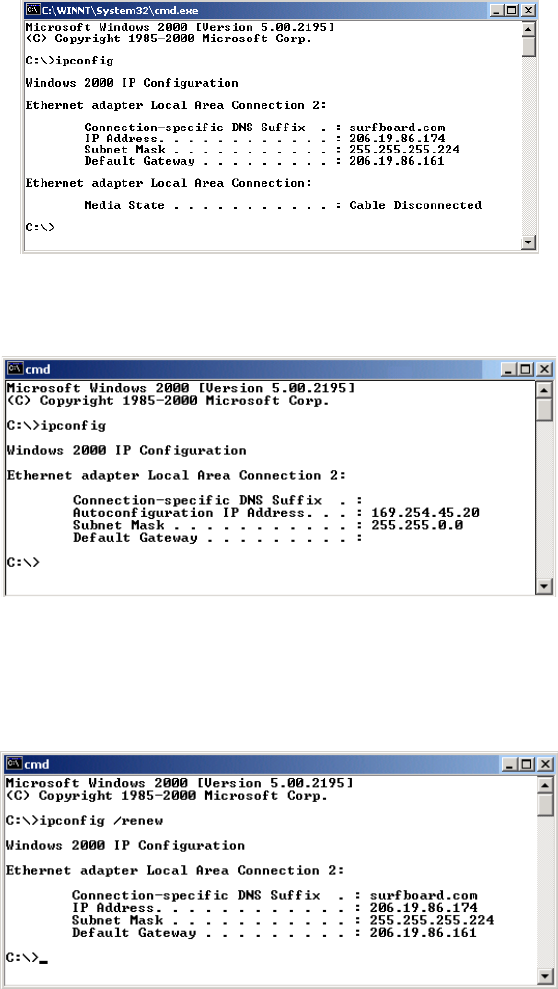
4. Type ipconfig and press ENTER to display the IP configuration information. A
display similar to the following indicates a normal configuration.
5. If, as in the following window, an Autoconfiguration IP Address is displayed, there
is an incorrect connection between the PC and the SVG2500, or there are
broadband network problems:
6. After verifying the broadband connections, renew the IP address.
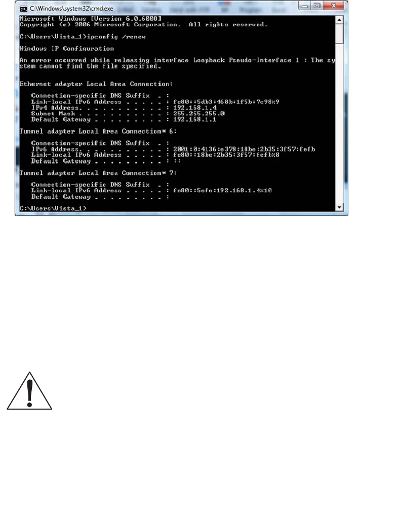
Do the following to renew the IP address:
1. At the command prompt, type ipconfig /renew and press Enter. If a valid IP
address is displayed as shown, Internet access should be available.
2. Type exit and press ENTER to return to Windows.
3. If after performing this procedure the computer cannot access the Internet, call
your Internet Service provider for help.
This document is uncontrolled pending incorporation in PDM
2 INSTALLATION
46
Verifying the IP Address in Windows Vista
Do the following to verify the IP address:
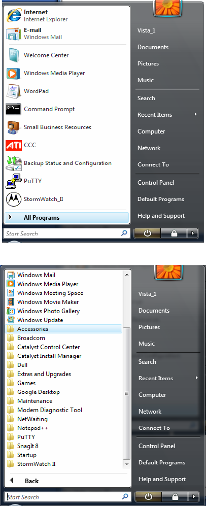
1. On the Windows Vista desktop, click Start to display the Start Menu.
2. Click All Programs.
3. Click Accessories.
This document is uncontrolled pending incorporation in PDM
2 INSTALLATION
47
4. Click Run to display the Run window.
5. Type cmd and click OK to open a command prompt window.
6. Type ipconfig and press ENTER to display the IP Configuration.
A display similar to the following indicates a normal configuration.
7. If, as in the following window, an Autoconfiguration IP Address is displayed, there
is an incorrect connection between the PC and the SVG2500, or there are
broadband network problems.
This document is uncontrolled pending incorporation in PDM
2 INSTALLATION
48
Do the following to renew the IP address:
1. At the command prompt, type ipconfig /renew and press Enter. If a valid IP
address is displayed as shown, Internet access should be available.
2. Type exit and press Enter to return to Windows.
If after performing this procedure the computer cannot access the Internet, call your
Internet Service provider for help.
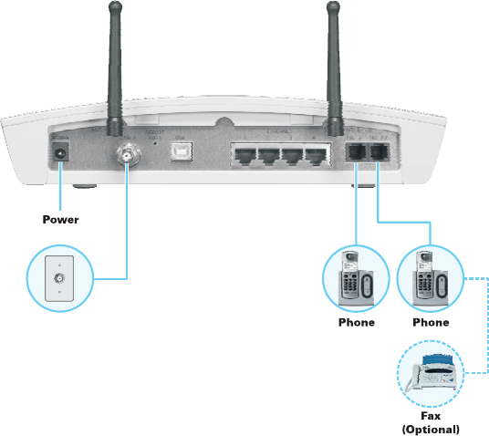
Installing the Telephone for VoIP
Your SVG2500 allows you to use your cable Internet connection for VoIP telephone
service. You must contact a VoIP service provider for this feature to work with the
SVG2500. You can connect up to two standard telephone lines using your SVG2500.
Caution!
To reduce the risk of fire, use only No. 26 or larger UL Listed or CSA Certified
Telecommunication Line Cord or national equivalent to connect a telephone line
to your SVG2500.
Contact your service provider before connecting your Motorola SVG2500 to your
existing telephone wiring. Do not connect the telephone wire to a traditional
telephone (PSTN) service.
Be sure the phone connectors are neither connected together nor connected to
wall jacks on the same network.
Use only a standard telephone. In many businesses, digital phones that connect
to a private branch exchange (PBX) do not operate with the SVG2500.
This document is uncontrolled pending incorporation in PDM
2 INSTALLATION
49
Connect your telephone by plugging a phone wire into the TEL 1/2 connector as
shown in the illustration below. You can also connect a second telephone line to the
TEL 2 connector. A two-line telephone may be connected to TEL 1/2.
Wall Mounting Your SVG2500
If you mount your SVG2500 on the wall, you must:
• Locate the unit as specified by the local or national codes governing residential or
business cable TV and communications services.
• Follow all local standards for installing a network interface unit/network interface
device (NIU/NID).
If possible, mount the unit to concrete, masonry, a wooden stud, or some other very
solid wall material. Use anchors if necessary (for example, if you must mount the
unit on drywall).
Do the following to mount your SVG2500 on the wall:
1. See Wall Mounting Template to print a copy of the template.
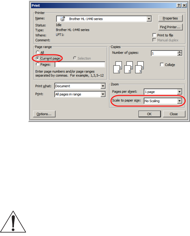
2. Click the Print icon or choose Print from the File menu to display the Print dialog
box.
This document is uncontrolled pending incorporation in PDM
2 INSTALLATION
50
The following image is from Adobe Acrobat Reader® version 7.0 running on
Windows 2000; there may be slight differences in your version.
To print the template only, select Current page as the Print Range. Be sure you print
the template at 100% scale. Be sure No Scaling is selected for Scale to paper size.
3. Click OK to print the template.
4. Measure the printed template with a ruler to ensure that it is the correct size.
5. Use a center punch to mark the center of the holes.
6. On the wall, locate the marks for the mounting holes.
7. Drill the holes to a depth of at least 1 1/2 inches (3.8 cm).
Caution!
Before drilling holes, check the structure for potential damage to water, gas, or electric
lines.
If necessary, seat an anchor in each hole.
Use M3.5 x 38 mm (#6 x 11/2 inch) screws with a flat underside and maximum
screw head diameter of 7.0 mm to mount the SVG2500.
This document is uncontrolled pending incorporation in PDM
2 INSTALLATION
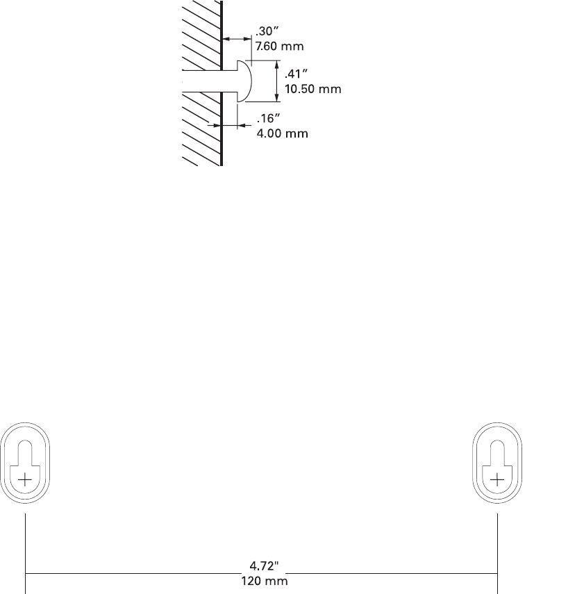
51
8. Using a screwdriver, turn each screw until part of it protrudes from the wall, as
shown in the following illustration.
There must be .09 inches (2.3 mm) between the wall and the underside of the
screw head.
9. Place the SVG2500 so the keyholes on the back of the unit are aligned above the
mounting screws. Be sure you do not damage the antennas.
10. Slide the SVG2500 down until it stops against the top of the keyhole opening.
Wall Mounting Template
You can print this page to use as a wall mounting template.
Be sure you print it at 100% scale. In Acrobat Reader, be sure that Fit To Page is not
selected in the Print dialog box.
Measure the printed template with a ruler to ensure that it is the correct size.
Revised drawing under
construction.
This document is uncontrolled pending incorporation in PDM
53
3 BASIC CONFIGURATION
The following topics provide information about basic SVG2500 configuration:
• Starting the SVG2500 Configuration Manager (CMGR)
• SVG2500 Menu Options Bar
• Changing the SVG2500 Default Password
• Getting Help
• Gaming Configuration Guidelines
• Exiting the SVG2500 Configuration Manager
For more advanced configuration information, see Configuring TCP/IP, Setting Up
Your Wireless LAN, or Installing USB Drivers.
For normal operation, you do not need to change most default settings. The following
caution statements summarize the issues you must be aware of:
Caution!
To prevent unauthorized configuration, change the default password immediately when
you first configure the SVG2500. See Changing the SVG2500 Default Password.
Firewalls are not foolproof. Choose the most secure firewall policy you can. See Section
7, SVG2500 Firewall Pages.
If you are using a wired LAN only and have no wireless clients, be sure you disable the
wireless interface. See Wireless 802.11b/g Basic Page to disable.
Starting the SVG2500 Configuration Manager (CMGR)
1. Open the web browser on a computer connected to the SVG2500 over an
Ethernet or USB connection.
Note: Do not attempt to configure the SVG2500 over a wireless connection.
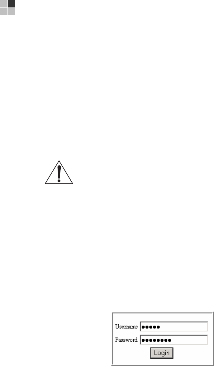
2. In the Address or Location field of your browser, type http://192.168.0.1 and press
Enter to display the Login page.
3. Type admin in the Username field (this field is case-sensitive).
4. Type motorola in the Password field (this field is case-sensitive).
This document is uncontrolled pending incorporation in PDM
3 BASIC CONFIGURATION
54
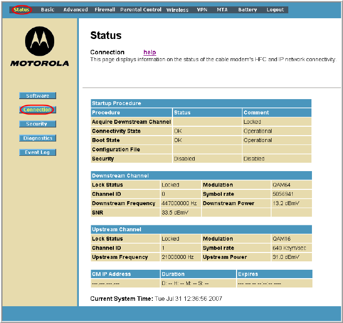
5. Click Login to display the SVG2500 Status Connection page.
The Status Connection page provides the following status information on the
network connection of the SVG2500:
• RF Downstream Channel, which uses lower cable frequencies to transmit data
• RF Upstream Channel, which uses higher cable frequencies to receive data
• IP lease information, which includes the current cable modem IP address (CM
IP address), the duration of both leases, and the expiration time of both leases
• Current system time from the DOCSIS timeserver
Click the Refresh button in your web browser any time you want to refresh the
information on this page.
If you have any problems starting the SVG2500 Configuration Manager (CMGR), see
Troubleshooting for information.
This document is uncontrolled pending incorporation in PDM
3 BASIC CONFIGURATION
55
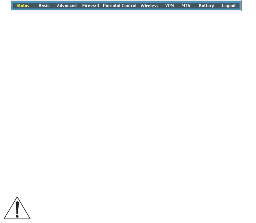
SVG2500 Menu Options Bar
The SVG2500 Menu Options bar is displayed along the top of the SVG2500
Configuration Manager window. When a menu option is selected, a top-level page
for that option is displayed.
Menu Option Pages Function
Status Provides information about the SVG2500 hardware and software, MAC
address, cable modem IP address, serial number, and related information.
You can also monitor your cable system connection. Additional pages
provide diagnostic tools and allow you to change your SVG2500 user
name and password.
Basic Views and configures SVG2500 IP-related configuration data, including
Network Configuration, WAN Connection Type, DHCP, and DDNS. The
Backup option allows you to save your SVG2500 configuration on your PC.
Advanced Configures and monitors how the SVG2500 routes IP traffic
Firewall Configures and monitors the SVG2500 firewall
Parental Control Configures and monitors the SVG2500 parental control feature
Wireless Configures and monitors SVG2500 wireless networking features
VPN Configures and monitors SVG2500 operation with a VPN
MTA Monitors the telephone features of your SVG2500
Battery Monitors the backup battery in your SVG2500
Logout Exits the SVG2500 Configuration Manager
Caution!
To prevent unauthorized configuration, immediately change the default password when
you first configure your Motorola SVG2500.
This document is uncontrolled pending incorporation in PDM
3 BASIC CONFIGURATION
56
SVG2500 Submenu Options
Additional features for each menu option are displayed by clicking a Submenu Option
in the left-panel of each page. The Status options are shown below. When selected,
the submenu option will be highlighted in yellow.
Changing the SVG2500 Default Password
Do the following to change the default password:
1. On the SVG2500 Status page, click the Security submenu option from the Status
Options list in the left panel to display the Status Security page.
2. In the Password Change Username field, type your new User Name. The default
password is “motorola” (this field is case sensitive).
3. In the New Password field, type the new password (this field is case sensitive).
4. In the Re-Enter New Password field, type the new password again (this field is
case sensitive).
5. In the Current Username Password field, type your old password.
6. Click Apply to save your changes.
This document is uncontrolled pending incorporation in PDM
3 BASIC CONFIGURATION
57
Restore Factory Defaults
To reset the user name and password back to the original factory settings:
1. Select Yes and then click Apply.
2. You must login with the default user name, ‘admin,’ and password, ‘motorola,’
after applying this change. All entries are case-sensitive.
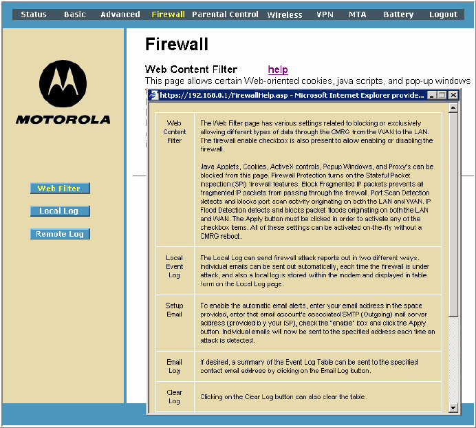
Getting Help
To retrieve help information for any menu option, click help on that page. As an
example, the Firewall help page is shown below:
You can use the Windows scroll bar to view additional items on the help screens.

This document is uncontrolled pending incorporation in PDM
3 BASIC CONFIGURATION
58
Gaming Configuration Guidelines
The following provides information about configuring the SVG2500 firewall and DMZ
for gaming.
Configuring the Firewall for Gaming
By default, the SVG2500 firewall is disabled. If, as recommended, you enable the
firewall, refer to the game’s documentation to ensure that the necessary ports are
open for use by that game.
The pre-defined SVG2500 firewall policies affect Xbox LIVE® as follows:
On the Firewall Web Content Filter Page, you may need to disable Firewall
Protection and IP Flood Detection.
Configuring Port Triggers
Because the SVG2500 has pre-defined port triggers for games using any of the
following applications, no user action is required to enable them:
• DirectX 7 and DirectX 8
• MSN Games by Zone.com
• Battle.net®
For a list of games supported by Battle.net, visit http://www.battle.net.
You may need to create custom port triggers to enable other games to operate
properly. To create custom port triggers, use the Advanced Configuring Port Triggers
Page.
Configuring a Gaming DMZ Host
Caution!
The gaming DMZ host is not protected by the firewall. It is open to communication or
hacking from any computer on the Internet. Consider carefully before configuring a
device to be in the DMZ.
Some games and game devices require one of:
• The use of random ports
• The forwarding of unsolicited traffic
For example, to connect a PlayStation®2 for PS2® online gaming, designate it as the
gaming DMZ host because the ports required vary from game to game. For these
games, Motorola recommends configuring the gaming computer or device as a
gaming DMZ device.
To configure a gaming DMZ device, on the Basic DHCP Page:
1. Reserve a private IP address for the computer or game device MAC address.
2. Designate the device as a DMZ device.
This document is uncontrolled pending incorporation in PDM
3 BASIC CONFIGURATION
59
You can reserve IP addresses for multiple devices, but only one can be designated
as the gaming DMZ at once.
Exiting the SVG2500 Configuration Manager
To logoff and close the SVG2500 Configuration Manager:
• Click Logout on the SVG2500 Menu Options bar
This document is uncontrolled pending incorporation in PDM
61
4 SVG2500 STATUS PAGES
The SVG2500 Status pages provide information about the SVG2500
hardware and software, MAC address, cable modem IP address,
serial number, and related information. You can also monitor your
cable system connection. Additional pages provide diagnostic tools
and allow you to change your SVG2500 user name and password.
You can click any Status submenu option to view or change the
status information for that option.
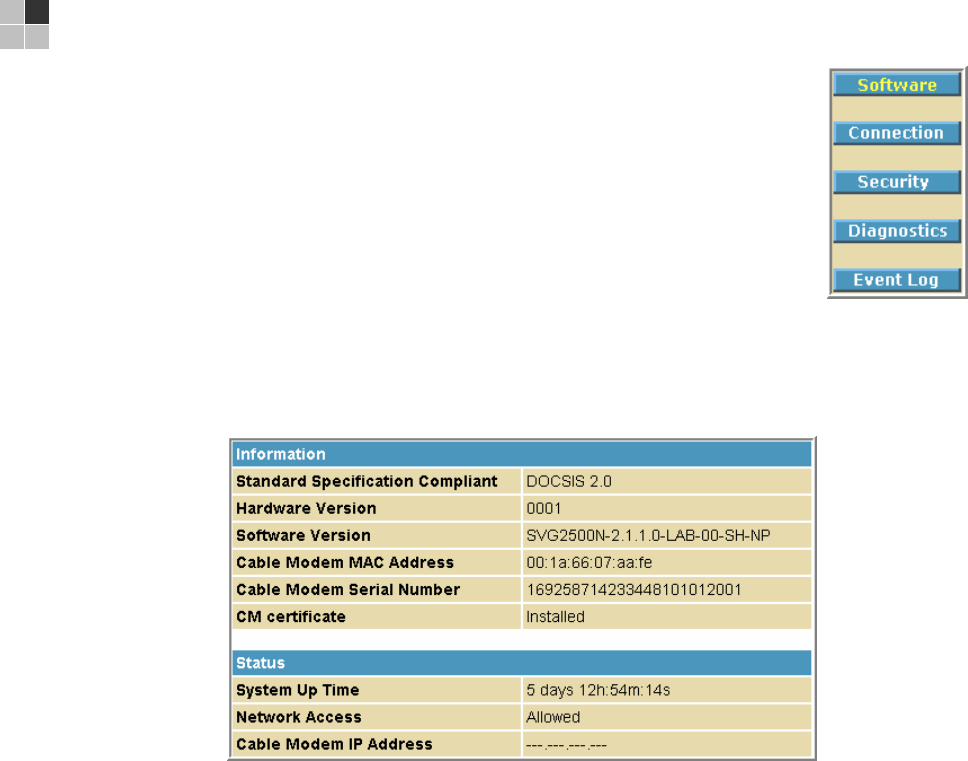
Status Software Page
This page displays information about the hardware version, software version, MAC
address, cable modem IP address, serial number, system "up" time, and network
registration status.
This document is uncontrolled pending incorporation in PDM
4 SVG2500 STATUS PAGES
62
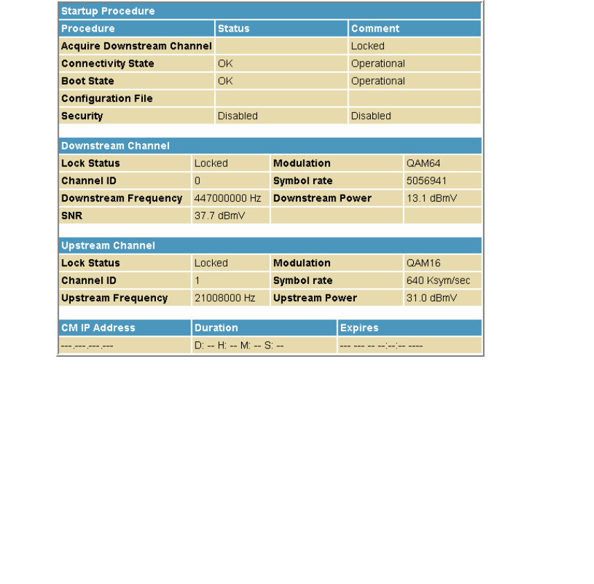
Status Connection Page
This page provides the HFC and IP network connectivity status of the SVG2500
cable modem.
The Connection page also displays IP lease information, including the current IP
address of the cable modem, the duration of both leases, the expiration time of both
leases, and the current system time from the DOCSIS timeserver.
You can click the Refresh button in your web browser to refresh the information on
this page at any time.
Field Description
Startup Procedure Startup status information about the cable modem.
Downstream Channel Status information about the RF downstream channels including
downstream channel frequency and downstream signal power
and modulation.
Upstream Channel Status information about the RF upstream channels including
upstream channel ID and upstream signal power and
modulation.
CM IP Address Current IP address of the cable modem, the duration and
expiration time of both IP leases, and the current system time
from the DOCSIS timeserver.
This document is uncontrolled pending incorporation in PDM
4 SVG2500 STATUS PAGES
63
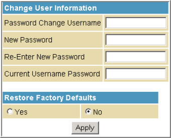
Status Security Page
This page allows you to define administrator access privileges by changing your
SVG2500 user name and password. It also allows you to reset your user name and
password to the default setting.
Changing the SVG2500 Default Password
1. In the Password Change Username field, type your new User Name. The default
password is “motorola” (this field is case sensitive).
2. In the New Password field, type the new password (this field is case sensitive).
3. In the Re-Enter New Password field, type the new password again (this field is
case sensitive).
4. In the Current Username Password field, type your old password.
5. Select Yes if you want to reset the user name and password to the original
factory settings.
6. Click Apply to update the user name password.
Note: You must login with the default user name, admin, and password, motorola,
after applying the restore factory settings change.
This document is uncontrolled pending incorporation in PDM
4 SVG2500 STATUS PAGES
64
Status Diagnostics Page
This page provides the following diagnostic tools for troubleshooting your IP
connectivity problems:
• Ping (LAN)
• Traceroute (WAN)
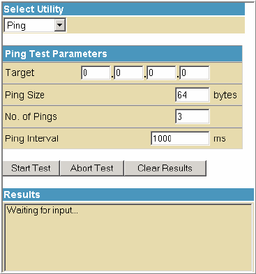
Ping Utility
Ping (Packet InterNet Groper) allows you to check connectivity between the
SVG2500 and other devices on the SVG2500 LAN. This utility sends a small packet of
data and then waits for a reply. When you Ping a computer IP address and receive a
reply, it confirms that the computer is connected to the SVG2500.
Testing Network Connectivity with the SVG2500
Perform the following steps to check connectivity between the SVG2500 and other
devices on the SVG2500 LAN:
1. Select Ping from the Select Utility drop-down list.
3. Enter the IP address of the computer you want to Ping in the Target field.
4. Enter the data packet size in bytes in the Ping Size field.
5. Enter the number of ping attempts in the No. of Pings field.
6. Enter the time between Ping send operations in milliseconds in the Ping Interval
field.
7. Click Start Test to begin the Ping operation. The Ping results will display in the
Results pane.
You can click Abort Test at any time during the test to stop the Ping operation.
8. Repeat steps 2 through 6 for each device you want to ping.
When done, click Clear Results to delete the Ping results in the Results pane.
This document is uncontrolled pending incorporation in PDM
4 SVG2500 STATUS PAGES
65
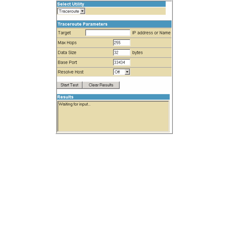
Traceroute Utility
Traceroute allows you to map the network path from the SVG2500 Configuration
Manager to a public host. Selecting Traceroute from the Select Utility drop-down list
will present alternate controls for the Traceroute utility.
Field Description
Target IP address
or Name
Enter the IP address or Host Name of the computer you want to
target for the Traceroute operation.
Max Hops Enter the maximum number of hops that the Traceroute operation
performs before stopping.
Data Size Enter the data packet size in bytes.
Base Port Sets the base UDP port number used by Traceroute.
The default is 33434. If a UDP port is not available, this field can be
used to specify an unused port range.
Resolve Host Select On to list the names of hosts found during the Traceroute
operation.
Select Off to list only the hosts IP addresses.
After entering the Traceroute parameters, click Start Test to begin the Traceroute
operation. The Traceroute results will display in the Results pane.
When done, click Clear Results to delete the Traceroute results in the Results pane.
This document is uncontrolled pending incorporation in PDM
4 SVG2500 STATUS PAGES
66
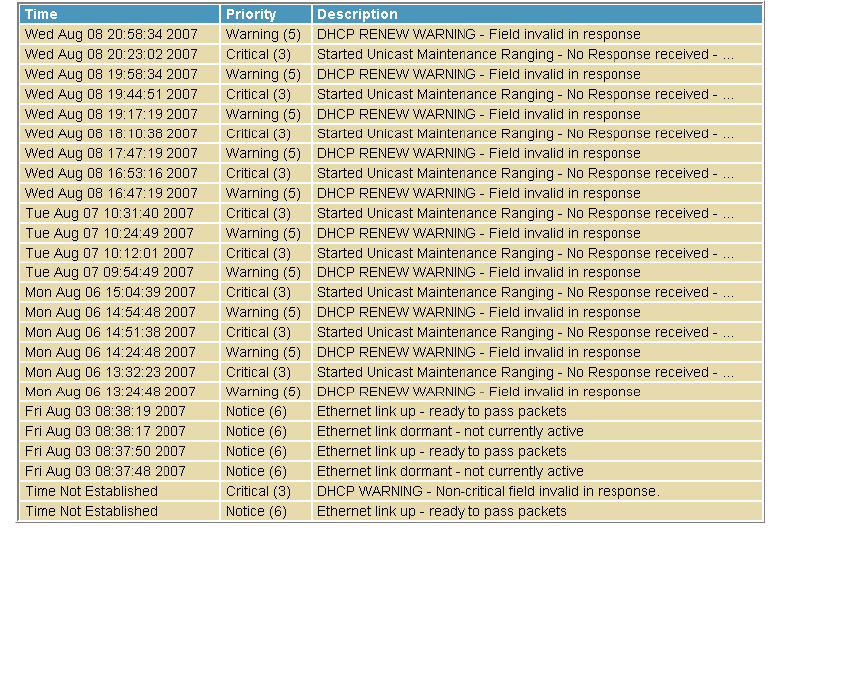
Status Event Log Page
This page lists the critical system events in chronological order. A sample Event log
is shown below:
Field Description
Time Indicates the date and time the error occurred
Priority Indicates the level of importance of the error
Description A brief definition of the error
This document is uncontrolled pending incorporation in PDM
67
5 SVG2500 BASIC PAGES
The SVG2500 Basic Pages allow you to view and configure SVG2500
IP-related configuration data, including Network Configuration, WAN
Connection Type, DHCP, and DDNS. The Backup option allows you to
save a copy of your SVG2500 configuration on your PC.
You can click any Basic submenu option to view or change the
configuration information for that option.
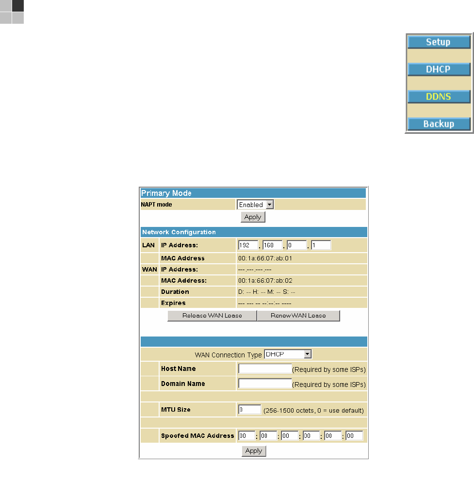
Basic Setup Page
This page allows you to configure the basic features of your SVG2500 gateway
related to your ISP connection.
Field Description
NAPT mode NAPT is a special case of NAT, where many IP numbers are hidden
behind a number of addresses. But in contrast to the original NAT, this
does not mean there can be only that number of connections at a time.
In NAPT mode, an almost arbitrary number of connections is multiplexed
using TCP port information. The number of simultaneous connections is
limited by the number of addresses multiplied by the number of available
TCP ports.

This document is uncontrolled pending incorporation in PDM
5 SVG2500 BASIC PAGES
68
Field Description
LAN
IP Address Enter the IP address of the SVG2500 on your private LAN.
MAC Address Media Access Control address — a set of 12 hexadecimal digits assigned
during manufacturing that uniquely identifies the hardware address of
the SVG2500 Access Point.
WAN
IP Address The public WAN IP address of your SVG2500 device, which is either
dynamically or statically assigned by your ISP.
MAC Address Media Access Control address — a set of 12 hexadecimal digits assigned
during manufacturing that uniquely identifies the hardware address of
the SVG2500 Access Point.
Duration Describes how long before your Internet connection expires. The WAN
lease will automatically renew itself when it expires.
Expires Displays the exact time and date the WAN lease expires.
Release WAN Lease Click to release WAN lease.
Renew WAN Lease Click to renew WAN lease.
WAN Connection Type DHCP or Static IP
If your ISP uses DHCP, select DHCP and enter a Host Name and Domain
name, if required.
If your ISP uses static IP addressing, select Static IP and enter the
information provided by your ISP for Static IP Address, Static IP Mask,
Default Gateway, Primary DNS, and Secondary DNS.
Host Name If the WAN Connection Type is DHCP, enter a Host Name if required by
your ISP.
Domain Name If the WAN Connection Type is DHCP, enter a Domain Name if required
by your ISP.
MTU Size Maximum Transmission Unit (MTU) is the largest size packet or frame
that can be sent. The default value is suitable for most users.
Spoofed MAC Address If the WAN Connection Type is Static IP, enter the information provided
by your ISP for Static IP Address, Static IP Mask, Default Gateway,
Primary DNS, and Secondary DNS.
When done, click Apply to save your changes.
This document is uncontrolled pending incorporation in PDM
5 SVG2500 BASIC PAGES
69
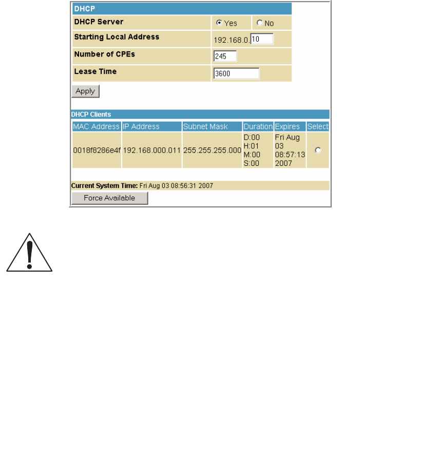
Basic DHCP Page
This page allows you to configure and view the status of the optional internal
SVG2500 DHCP (Dynamic Host Configuration Protocol) server for the LAN.
Caution!
Do not modify these settings unless you are an experienced network administrator with
strong knowledge of IP addressing, subnetting, and DHCP.
Field Description
DHCP Server Select Yes to enable the SVG2500 DHCP Server.
Select No to disable the SVG2500 DHCP Server.
Starting Local Address Enter the starting IP address to be assigned by the SVG2500 DHCP
server to clients in dotted-decimal format. The default is 192.168.0.2.
Number of CPEs Sets the number of clients for the SVG2500 DHCP server to assign a
private IP address. There are 245 possible client addresses. The
default is 245.
Lease Time Sets the time in seconds that the SVG2500 DHCP server leases an
IP address to a client. The default is 3600 seconds (60 minutes).
DHCP Clients Lists DHCP client device information.
When done, click Apply to save your changes.
To renew a DHCP client IP address, choose Select and then click Force Available.
This document is uncontrolled pending incorporation in PDM
5 SVG2500 BASIC PAGES
70
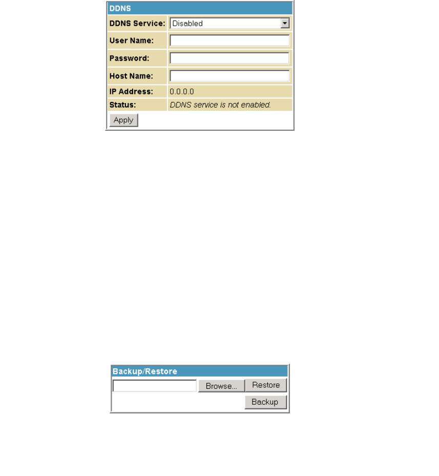
Basic DDNS Page
This page allows you to set up the Dynamic Domain Name System (DDNS) service.
The DDNS service allows you to assign a static Internet domain name to a dynamic
IP address, which allows your SVG2500 to be more easily accessed from various
locations on the Internet.
Field Description
DDNS Service Select Disable or wwwDynDNS.org to enable the DDNS Service.
User Name Enter your DynDNS user name.
Password Enter your DynDNS Password.
Host Name Enter your DDNS Host Name.
IP Address Lists IP information.
Status Displays the DDNS service status: enabled or disabled
When done, click Apply to save your changes.
Basic Backup Page
This page allows you to save your current SVG2500 configuration settings locally on
your computer or restore previously saved configurations.
Field Description
Restore Lets you restore a previously saved configuration.
Backup Lets you create a backup copy of the current configuration.
Restoring Your SVG2500 Configuration
1. Type the path with the file name where the backup file is located on your
computer, or click Browse to locate the file.
2. Click Restore to recreate your previously saved SVG2500 settings.
This document is uncontrolled pending incorporation in PDM
5 SVG2500 BASIC PAGES
71
Backing Up Your SVG2500 Configuration
1. Type the path with the file name where you want to store your backup file on
your computer, or click Browse to locate the file.
2. Click Backup to create a backup of your SVG2500 settings.
This document is uncontrolled pending incorporation in PDM
73
6 SVG2500 ADVANCED PAGES
The SVG2500 Advanced Pages allow you to configure the advanced
features of the SVG2500, including IP Filtering, MAC Filtering, Port
Filtering, Port Forwarding, Port Triggers, DMZ Host, and RIP Setup.
You can click any Advanced submenu option to view or change the
advanced configuration information for that option.
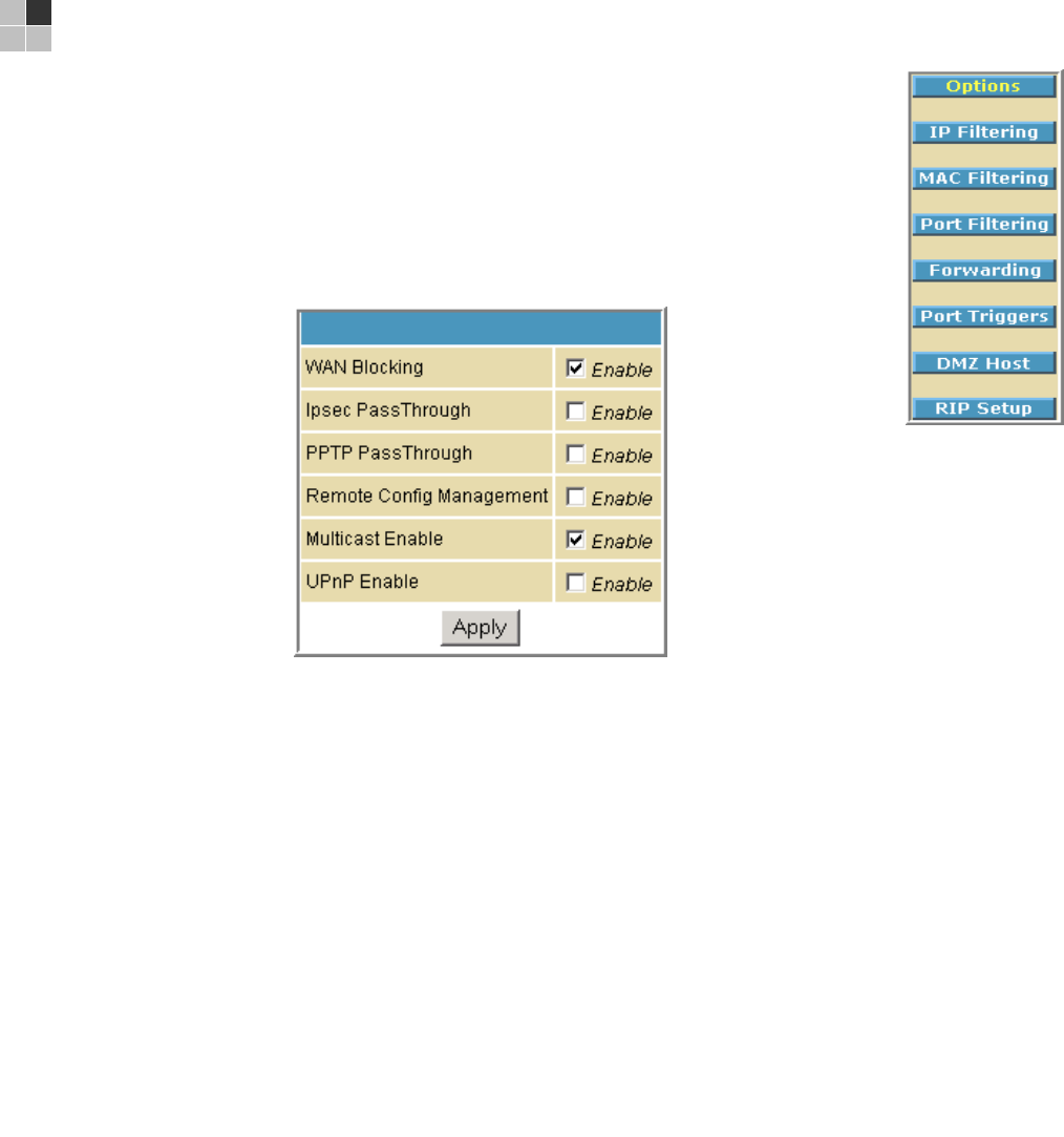
Advanced Options Page
This page allows you to set the operating modes for adjusting how the SVG2500
device routes IP traffic.
Field Description
WAN Blocking Prevents the SVG2500 Configuration Manager or the PCs behind
it from being visible to other computers on the SVG2500 WAN.
Checkmark Enable to turn on this option or uncheck to disable it.
Ipsec PassThrough Enables the IpSec Pass-Through protocol to be used through the
SVG2500 Configuration Manager so that a VPN device (or
software) may communicate properly with the WAN.
Checkmark Enable to turn on this option or uncheck to disable it.
PPTP PassThrough Enables the Point-to-Point Tunneling Protocol (PPTP) Pass-
Through protocol to be used through the SVG2500
Configuration Manager so that a VPN device (or software) may
communicate properly with the WAN.
Checkmark Enable to turn on this option or uncheck to disable it.

This document is uncontrolled pending incorporation in PDM
6 SVG2500 ADVANCED PAGES
74
Field Description
Remote Configuration
Management
Allows remote access to the SVG2500 Configuration Manager.
This enables you to configure the SVG2500 WAN by accessing
the WAN IP address at Port 8080 of the configuration manager
from anywhere on the Internet. For example, in the browser
URL window, type http://WanIPAddress:8080/ to access the
SVG2500 Configuration Manager remotely.
Checkmark Enable to turn on this option or uncheck to disable it.
Multicast Enable Allows multicast-specific traffic (denoted by a multicast specific
address) to be passed to and from the PCs on the private
network behind the configuration manager.
Checkmark Enable to turn on this option or uncheck to disable it.
UPnP Enable Turns on the Universal Plug and Play protocol (UPnP) agent in
the configuration manager. If you are running a CPE (client)
application that requires UPnP, select this box.
Checkmark Enable to turn on this option or uncheck to disable it.
When done, click Apply to save your changes.
This document is uncontrolled pending incorporation in PDM
6 SVG2500 ADVANCED PAGES
75
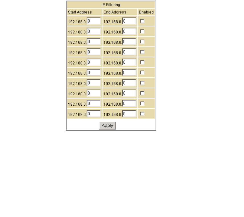
Advanced IP Filtering Page
This page allows you to define which local PCs will be denied access to the
SVG2500 WAN. You can configure IP address filters to block Internet traffic to
specific network devices on the LAN by entering starting and ending IP address
ranges. Note that you only need to enter the LSB (Least-significant byte) of the IP
address; the upper bytes of the IP address are set automatically from the SVG2500
Configuration Manager’s IP address.
The Enabled option allows you to store filter settings commonly used but not have
them active.
Field Description
Start Address Enter the starting IP address range of the computers for which you
want to deny access to the SVG2500 WAN. Be sure to only enter the
least significant byte of the IP address.
End Address Enter the ending IP address range of the computers you want to deny
access to the SVG2500 WAN. Be sure to only enter the least significant
byte of the IP address.
Enabled Activates the IP address filter, when selected.
Checkmark Enabled for each range of IP addresses you want to deny
access to the SVG2500 WAN.
When done, click Apply to activate and save your settings.
This document is uncontrolled pending incorporation in PDM
6 SVG2500 ADVANCED PAGES
76
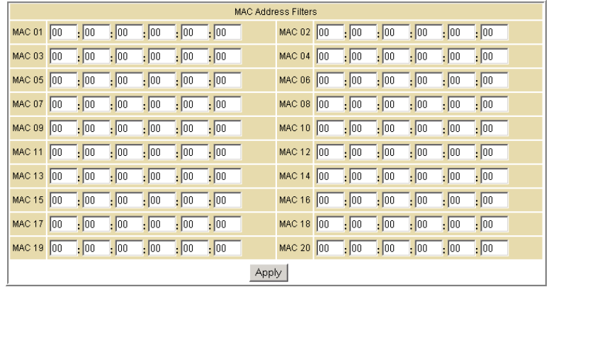
Advanced MAC Filtering Page
This page allows you to define Media Access Control (MAC) address filters to
prevent PCs from sending outgoing TCP/UDP traffic to the WAN via their MAC
addresses. This is useful because the MAC address of a specific NIC card never
changes, unlike its IP address, which can be assigned via the DHCP server or hard-
coded to various addresses over time.
Field Description
MAC nn Media Access Control address — a unique set of 12 hexadecimal digits
assigned to a PC during manufacturing
Setting a MAC Address Filter
1. Enter the MAC address in the MAC nn field for each PC you want to block.
2. When done, click Apply.
This document is uncontrolled pending incorporation in PDM
6 SVG2500 ADVANCED PAGES
77
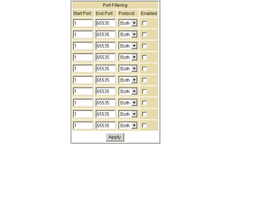
Advanced Port Filtering Page
This page allows you to define port filters to prevent all devices from sending
outgoing TCP/UDP traffic to the WAN on specific IP port numbers. By specifying a
starting and ending port range, you can determine what TCP/UDP traffic is allowed
out to the WAN on a per-port basis.
Note: The specified port ranges are blocked for ALL PCs, and this setting is not IP
address or MAC address specific. For example, if you wanted to block all PCs on the
private LAN from accessing HTTP sites (or "web surfing"), you would set the "Start
Port" to 80, "End Port" to 80, "Protocol" to TCP, checkmark Enabled, and then click
Apply.
Field Description
Start Port Enter the starting port number.
End Port Enter the ending port number.
Protocol Select TCP, UDP, or Both
Enabled Checkmark for each port that you want to activate the IP port filters.
This document is uncontrolled pending incorporation in PDM
6 SVG2500 ADVANCED PAGES
78
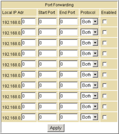
Advanced Port Forwarding Page
This page allows you to run a publicly accessible server on the LAN by specifying the
mapping of TCP/UDP ports to a local PC. This enables incoming requests on specific
port numbers to reach web servers, FTP servers, mail servers, etc. so that they can
be accessible from the public Internet.
A table of commonly used Port numbers is also displayed on the page for your
convenience.
To map a port, you must enter the range of port numbers that should be forwarded
locally and the IP address to which traffic to those ports should be sent. If only a
single port specification is desired, enter the same port number in the "start" and
"end" locations for that IP address.
The ports used by some common applications are:
• FTP: 20, 21
• HTTP: 80
• NTP: 123
• Secure Shell: 22
• SMTP e-mail: 25
• Telnet: 23
This document is uncontrolled pending incorporation in PDM
6 SVG2500 ADVANCED PAGES
79
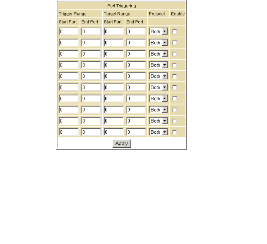
Advanced Port Triggers Page
This page allows you to configure dynamic triggers to specific devices on the LAN.
This allows for special applications that require specific port numbers with
bi-directional traffic to function properly. Applications such as video conferencing,
voice, gaming, and some messaging program features may require these special
settings.
The Advanced Port Triggers are similar to Port Forwarding except that they are not
static ports held open all the time. When the Configuration Manager detects
outgoing data on a specific IP port number set in the "Trigger Range," the resulting
ports set in the "Target Range" are opened for incoming (sometimes referred to as
bi-directional ports) data. If no outgoing traffic is detected on the "Trigger Range"
ports for 10 minutes, the "Target Range" ports will close. This is a safer method for
opening specific ports for special applications (e.g. video conferencing programs,
interactive gaming, file transfer in chat programs, etc.) because they are dynamically
triggered and not held open constantly or erroneously left open via the router
administrator and exposed for potential hackers to discover.
Field Description
Trigger Range
Start Port The starting port number of the Port Trigger range.
End Port The ending port number of the Port Trigger range.
Target Range
Start Port The starting port number of the Port Trigger range.
End Port The ending port number of the Port Trigger range.
Protocol Choice of TCP or UDP, or Both
Enable Select checkbox to activate the IP port triggers.
This document is uncontrolled pending incorporation in PDM
6 SVG2500 ADVANCED PAGES
80
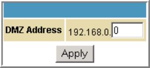
Advanced DMZ Host Page
This page allows you to specify the "default" recipient of WAN traffic that NAT is
unable to translate to a known local PC. The DMZ (De-militarized Zone) hosting (also
commonly referred to as "Exposed Host") can also be described as a computer or
small sub-network that sits between the trusted internal private LAN and the
untrusted public Internet.
You may configure one PC to be the DMZ host. This setting is generally used for PCs
using "problem" applications that use random port numbers and do not function
correctly with specific port triggers or the port forwarding setups mentioned earlier.
If a specific PC is set as a DMZ Host, remember to set this back to "0" when you are
finished with the needed application, since this PC will be effectively exposed to the
public Internet, though still protected from Denial of Service (DoS) attacks via the
Firewall.
Setting Up the DMZ Host
1. Enter the computer’s IP address.
2. Click Apply to activate the selected computer as the DMZ host.
This document is uncontrolled pending incorporation in PDM
6 SVG2500 ADVANCED PAGES
81
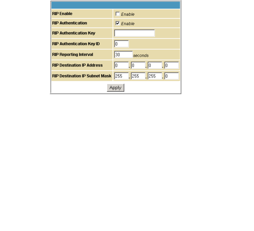
Advanced Routing Information Protocol Setup Page
This page allows you to configure Routing Information Protocol (RIP) parameters
related to authentication, destination IP address/subnet mask, and reporting
intervals. RIP automatically identifies and uses the best known and quickest route to
any given destination address. To help reduce network congestion and delays, the
Advanced RIP setup is used in WAN networks to identify and use the best known
and quickest route to given destination addresses.
RIP is a protocol that requires negotiation from both sides of the network (i.e.,
CMRG and CMTS). The ISP would normally set this up to match their CMTS settings
with the configuration in the CMRG.
Note: RIP messaging will only be sent upstream when running in Static IP
Addressing mode on the Basic - Setup page. You must enable Static IP Addressing
and then set the WAN IP network information! RIP is normally a function that is
tightly controlled via the ISP. RIP Authentication Keys and IDs are normally held as
secret information from the end user to prevent unauthorized RIP settings.
Field Description
RIP Enable Enables or disables the RIP protocol.
This protocol helps the router dynamically adapt to the
changes in the network. RIP is now considered obsolete since
newer routing protocols, such as OSPF and ISIS, have been
introduced.
RIP Authentication If this field is enabled, a plain text password or a shared key
authentication is added to the RIP packet in order for the CPE
and the wireless router to authenticate each other.
RIP Authentication Key Used to encrypt the plain text password that is enclosed in
each RIP packet.
If you are using the shared key authentication in RIP, you will
need to provide a key.
RIP Authentication Key ID An unsigned 8-bit field in the RIP packet. This field identifies
the key used to create the authentication data for the RIP
packet, and it also indicates the authentication algorithm.

This document is uncontrolled pending incorporation in PDM
6 SVG2500 ADVANCED PAGES
82
Field Description
RIP Reporting Interval Determines how long before a RIP packet is sent out to the
CPE.
RIP Destination IP Address Location where the RIP packet is sent to update the routing
table in your CPE.
RIP Destination IP Subnet Mask Specifies which CPE you want to receive the RIP packet.

This document is uncontrolled pending incorporation in PDM
83
7 SVG2500 FIREWALL PAGES
The SVG2500 Firewall Pages allow you to configure the SVG2500
firewall filters and firewall alert notifications.
You can click any Firewall submenu option to view or change the
firewall configuration information for that option.
For information about how the firewall can affect gaming, see
Gaming Configuration Guidelines.
The predefined policies provide outbound Internet access for computers on the
SVG2500 LAN. The SVG2500 firewall uses stateful inspection to allow inbound
responses when there already is an outbound session running corresponding to the
data flow. For example, if you use a web browser, outbound HTTP connections are
permitted on port 80. Inbound responses from the Internet are allowed because an
outbound session is established.
When required, you can configure the SVG2500 firewall to allow inbound packets
without first establishing an outbound session. You also need to configure a port
forwarding entry on the Advanced Port Forwarding Page or a DMZ client on the
Advanced DMZ Host Page.
This document is uncontrolled pending incorporation in PDM
7 SVG2500 FIREWALL PAGES
84
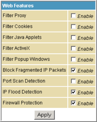
Firewall Web Content Filter Page
This page allows you to configure the firewall by enabling or disabling various Web
filters related to blocking or exclusively allowing different types of data through the
Configuration Manager from the WAN to the LAN.
Java Applets, Cookies, ActiveX controls, popup windows, and Proxies can be blocked
from this page. Firewall Protection turns on the Stateful Packet Inspection (SPI)
firewall features. Block Fragmented IP packets prevent all fragmented IP packets
from passing through the firewall. Port Scan Detection detects and blocks port scan
activity originating on both the LAN and WAN. IP Flood Detection detects and blocks
packet floods originating on both the LAN and WAN.
Checkmark Enable for each Web filter you want to set for the firewall, and then click
Apply. The Web filters will activate without having to reboot the SVG2500
Configuration Manager.
Note: If you deselect all the Web filters, you will disable the firewall. This is not
recommended.
This document is uncontrolled pending incorporation in PDM
7 SVG2500 FIREWALL PAGES
85
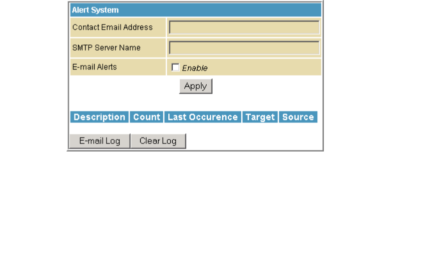
Firewall Local Log Page
This page allows you to set up how to send notification of the firewall event log in
either of the following formats:
• Individual e-mail alerts sent out automatically each time the firewall is under
attack
• Local log is stored within the modem and displayed in table form on the Local
Log page
Field Description
Contact Email Address Your email address
SMTP Server Name Name of the e-mail (Simple Mail Transfer Protocol) server.
The firewall page needs your email server name to send a
firewall log to your email address. You can obtain the
SMTP server name from your Internet service provider.
Email Alerts Enable or disable emailing firewall alerts.
This document is uncontrolled pending incorporation in PDM
7 SVG2500 FIREWALL PAGES
86
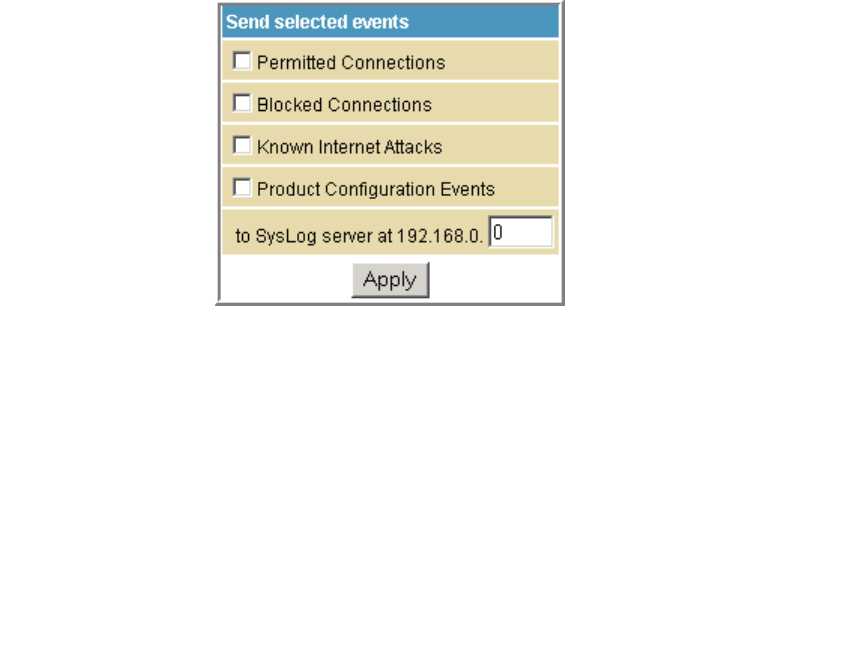
Firewall Remote Log Page
This page allows you to send firewall attack reports out to a standard SysLog server
so many instances can be logged over a long period of time. You can select individual
attack or configuration items to send to the SysLog server so that only the items of
interest will be monitored. You can log permitted connections, blocked connections,
known Internet attack types, and CMRG configuration events. The SysLog server
must be on the same network as the Private LAN behind the Configuration Manager
(typically 192.168.0.x). To activate the SysLog monitoring feature, check all desired
event types to monitor and enter the last byte of the IP address of the SysLog
server. Normally, the IP address of this SysLog server would be hard-coded so that
the address does not change and always agrees with the entry on this page.
Field Description
Permitted Connections Check for the server to e-mail you logs of who is connecting to
your network.
Blocked Connections Check for the server to e-mail you logs of who is blocked from
connecting to your network.
Known Internet Attacks Check for the server to e-mail you logs of known Internet attacks
against your network.
Product Configuration Events Check for the server to e-mail you logs of the basic product
configuration events logs.
To SysLog server at 192.168.0. Enter the last digits from 10 to 254 of your SysLog server’s IP
address.
When done, click Apply.
This document is uncontrolled pending incorporation in PDM
87
8 SVG2500 PARENTAL CONTROL PAGES
The SVG2500 Parental Control Pages allow you to configure
access restrictions to a specific device connected to the SVG2500
LAN.
You can click any Parental Control submenu option to view or
change the configuration information for that option.
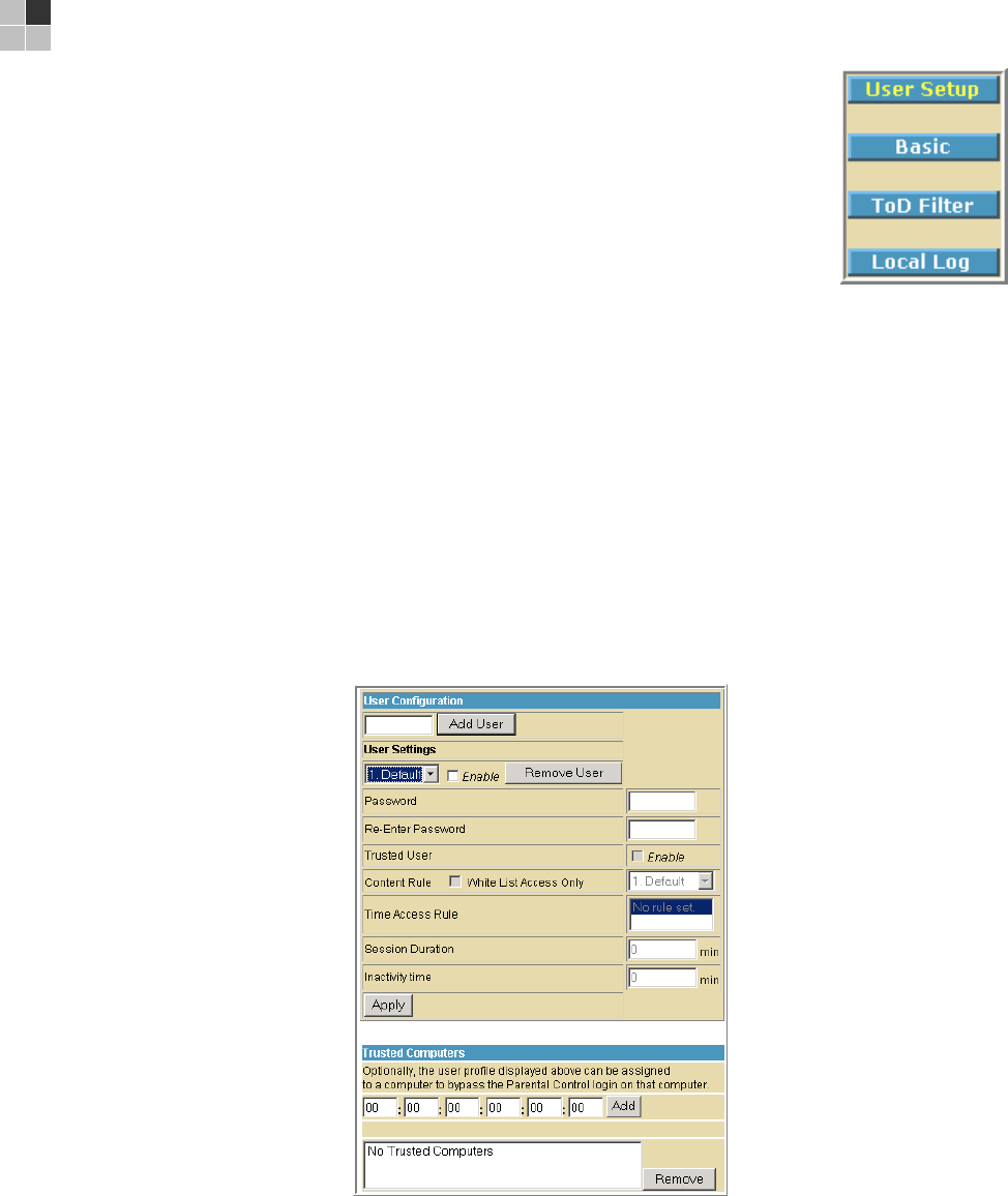
Parental Control User Setup Page
This page is the master page. Each user is linked to a specified time access rule,
content filtering rule, and login password to get to the filtered content. You may also
specify a user as a "trusted user," which means that person will have access to all
Internet content regardless of the filters that you define. You can use the Trusted
User checkbox as a simple override to grant a user full access, while storing all of
the filtering settings for easy availability.
You can also enable Internet session duration timers, which set a limited amount of
time for Internet access from the rules you select. The user must enter their
password only the first time to access the Internet. It is not necessary to enter the
password each time a new web page is accessed. In addition, there is a password
inactivity timer. If there is no Internet access for the specified time in minutes, the
user must login again. These timed logins ensure that a specific user uses the
Internet gateway appropriately.

This document is uncontrolled pending incorporation in PDM
8 SVG2500 PARENTAL CONTROL PAGES
88
Field Description
Add User Adds a user to set the parental controls for a specific user.
User Settings Select the user for whom you want to modify their access
restrictions.
Checkmark Enable to select the user.
Click Remove User to delete the user from Parental Controls.
Password Enter a user password to log onto the Internet.
Re-Enter Password Enter the password again for confirmation.
Trusted User The selected user will have full access to Internet content, thus
overriding any set filters.
Checkmark Enable to override set filters without having to turn off
filter settings.
Content Rule Used to specify which websites a selected user is allowed to
access.
Check White List Access Only and choose a user from the drop-down
list.
Time Access Rule You can choose a rule that restricts when a selected user can
use the Internet.
Session Duration You can set the amount of time a selected user can use the
Internet.
Inactivity time You can set the amount of inactivity time before the Internet
automatically closes for a selected user.
Trusted Computers You can enter a selected user’s CPE MAC address so that CPE
can access the Internet without being censored by the Parental
Control.
When done entering the MAC address, click Add.
When done, click Apply to activate and save any changes you made.
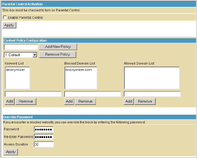
This document is uncontrolled pending incorporation in PDM
8 SVG2500 PARENTAL CONTROL PAGES
89
Parental Control Basic Setup Page
This page allows you to set rules to block certain kinds of Internet content and
certain Web sites.
After you have changed your Parental Control settings, click the appropriate Apply,
Add, or Remove button.
Click Refresh in your web browser window to view your current settings.
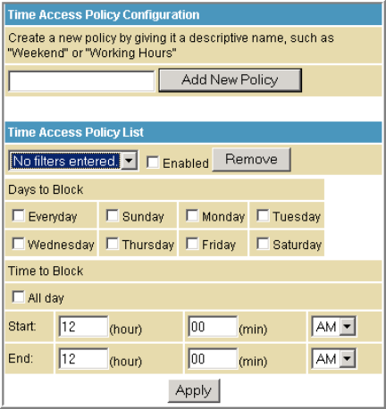
This document is uncontrolled pending incorporation in PDM
8 SVG2500 PARENTAL CONTROL PAGES
90
Parental Control ToD Access Policy Page
This page allows you to block all Internet traffic to and from specified devices on
your SVG2500 network based on the day and time settings you specify. You can set
policies to block Internet traffic for the entire day or just certain time periods within
each day for specific users. You can add up to 30 eight-character categories (filter
names) with different day and time settings. You enter a name for each time filter in
the Add New Policy field. Any time filter for Internet access can be enabled or
disabled at any time.
The time filters for limited Internet access are applied for each user in the Time
Access Rule field on the Parental Control User Setup Page.
Once each category change has been made, the user must click Apply at the bottom
of the page to store and activate the settings. These same category names for
blocking profiles show up in the Parental Control section on the User Setup page in
the "Time Access Rules" section. On that page, each user can be assigned up to four
of these categories simultaneously.

This document is uncontrolled pending incorporation in PDM
8 SVG2500 PARENTAL CONTROL PAGES
91
Parental Control Event Log Page
This page displays a report of the Parental Control event log. The event log is a
running list of the last 30 Parental Control access violations that include the following
items on Internet traffic:
• If the user's Internet access is blocked (time filter)
• If a blocked keyword is detected in the URL
• If a blocked domain is detected in the URL
• If the online lookup service detects that the URL falls under a blocked category
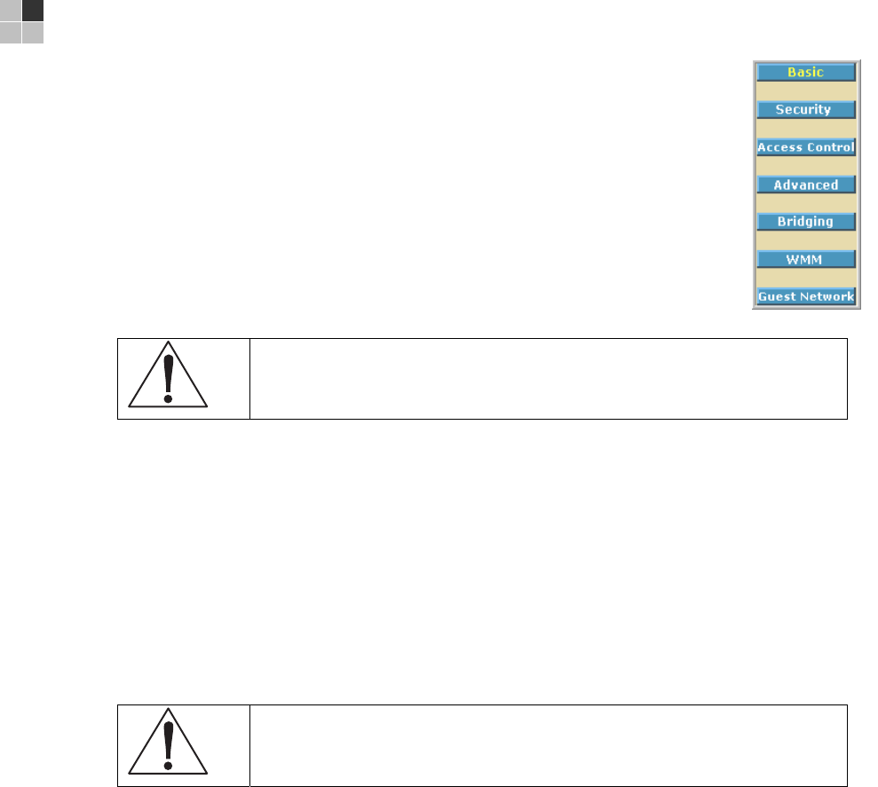
This document is uncontrolled pending incorporation in PDM
93
9 SVG2500 WIRELESS PAGES
The SVG2500 Wireless Pages allow you to configure your wireless
LAN (WLAN). You can click any Wireless submenu option to view or
change the configuration information for that option. WPA encryption
provides higher security than WEP encryption, but older wireless
client cards may not support the newer WPA encryption methods.
Setting Up Your Wireless LAN
You can use the SVG2500 as an access point for a wireless LAN
(WLAN) without changing its default settings.
Caution!
To prevent unauthorized eavesdropping or access to WLAN data, you must
enable wireless security. The default SVG2500 settings provide no wireless
security. After your WLAN is operational, be sure to enable wireless security.
To enable security for your WLAN, you can do the following on the SVG2500:
To Perform Use in SVG2500 Configuration Mgr
Encrypt wireless transmissions
and restrict WLAN access
Encrypting Wireless
LAN Transmissions
Wireless 802.11b/g Privacy Page
Further prevent unauthorized
WLAN intrusions
Restricting Wireless
LAN Access
Wireless 802.11b/g Access Control
Page
Caution!
Never provide your SSID, WPA or WEP passphrase, or WEP key to anyone who
is not authorized to use your WLAN.
Connect at least one computer to the SVG2500 Ethernet or USB port to perform
configuration. Do not attempt to configure the SVG2500 over a wireless connection.
You need to configure each wireless client (station) to access the SVG2500 LAN as
described in Configuring the Wireless Clients.
Another step to improve wireless security is to place wireless components away
from windows. This decreases the signal strength outside the intended area.

This document is uncontrolled pending incorporation in PDM
9 SVG2500 WIRELESS PAGES
94
Encrypting Wireless LAN Transmissions
To prevent unauthorized viewing of data transmitted over your WLAN, you must
encrypt your wireless transmissions.
Use the Wireless 802.11b/g Privacy Page to encrypt your transmitted data. Choose
one of:
Configure on the SVG2500 Required on Each Wireless Client
If all of your wireless clients support
Wi-Fi Protected Access (WPA),
Motorola recommends configuring
WPA on the SVG2500
If you use a local pre-shared key (WPA-PSK) passphrase,
you must configure the identical passphrase to the
SVG2500 on each wireless client. Home and small-office
settings typically use a local passphrase.
Otherwise, configure WEP on
the SVG2500
You must configure the identical WEP key to the SVG2500
on each wireless client.
If all of your wireless clients support WPA encryption, Motorola recommends using
WPA instead of WEP because WPA:
• Provides much stronger encryption and is more secure
• Provides authentication to ensure that only authorized users can log in to your
WLAN
• Is much easier to configure
• Uses a standard algorithm on all compliant products to generate a key from a
textual passphrase
• Will be incorporated into the new IEEE 802.11i wireless networking standard
For new wireless LANs, Motorola recommends purchasing client adapters that
support WPA encryption.
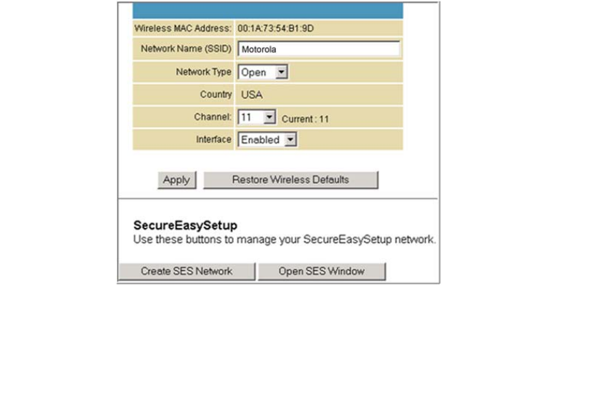
This document is uncontrolled pending incorporation in PDM
9 SVG2500 WIRELESS PAGES
95
Wireless 802.11b/g Basic Page
This page allows you to configure the Access Point parameters including the SSID
and channel number.
Creating a SecureEasySetup™ (SES) network ensures strong security for preventing
unauthorized wireless network access. However, traditional wireless network
installation can be a complicated and time-consuming task, requiring the user to
possess the technical know-how to manually enter several settings (such as network
name, and encryption key or WPA pass phrase) on each Wi-Fi device. Motorola
SecureEasySetup technology dramatically simplifies installation by automating the
processes of configuring new wireless networks and adding devices to existing
networks. SecureEasySetup establishes a private connection between the devices
and automatically configures the network's Service Set Identifier (SSID) and
WPA-Personal security settings. It configures a new network only on each new
device that is authorized to join the network.
Field Description
Wireless MAC Address Shows the MAC address of the installed wireless card. It is not
configurable.
Network Name (SSID) Sets the Network Name (also known as SSID) of the wireless
network. This is a 1-32 ASCII character string.

This document is uncontrolled pending incorporation in PDM
9 SVG2500 WIRELESS PAGES
96
Field Description
Network Type Selecting Closed prevents the network name from appearing in a
wireless client’s "Available Wireless Networks" list. Only clients who
already know the network name will be able to connect. Closed
disables the SSID broadcast in beacon packets.
Selecting Open allows broadcasting to the SSID in beacon packets.
Country Restricts the channel set based on the country's regulatory
requirements. This is a display-only field.
Channel Selects the channel for access point (AP) operation. The list of
available channels depends on the designated country. For this field,
the channel selected on the wireless clients on your WLAN must be
the same as the one selected on the SVG2500.
Interface Allows the access point to be Enabled or Disabled.
Create SES
Network
This action button generates a new SecureEasySetup network,
applies the configuration to the wireless interface, and stores the
settings to non-volatile memory. It enables WPA-PSK authentication
and generates a unique Network Name (SSID) and random,
16-character Pre-Shared Key (PSK). The pop-up window shown
informs the user a SecureEasySetup network has been successfully
created.
Open SES Window This action button opens a 2-minute security window that allows a
SecureEasySetup client to connect. Only 1 SecureEasySetup client
may connect during an Open Window period. If you have more than
1 client to connect to your SecureEasySetup, you must open the
window multiple times. When the SecureEasySetup window is
open, the pop-up window below indicates the CMRG is waiting for a
SecureEasySetup client.
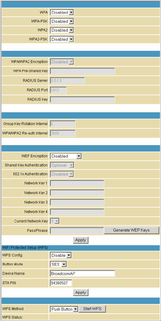
This document is uncontrolled pending incorporation in PDM
9 SVG2500 WIRELESS PAGES
97
Wireless 802.11b/g Privacy Page
This page allows you to configure the WEP keys and/or passphrase.

This document is uncontrolled pending incorporation in PDM
9 SVG2500 WIRELESS PAGES
98
Field Description
WPA
WPA2
Enables or disables Wi-Fi Protected Access (WPA) encryption.
WPA-PSK
WPA2-PSK
Enables or disables a local pre-shared key (WPA-PSK) passphrase.
WPA/WPA2 Encryption When using WPA or WPA-PSK authentication, these WPA
encryption modes can be set: TKIP, AES, or TKIP + AES.
AES (Advanced Encryption Standard) provides the strongest
encryption, while TKIP (Temporal Key Integrity Protocol) provides
strong encryption with improved compatibility. The TKIP + AES
mode allows both TKIP and AES-capable clients to connect.
WPA Pre-Shared Key Sets the WPA Pre-Shared Key (PSK). This is an 8-63 ASCII character
string, or a 64-digit hex number. Enabled when the Network
Authentication method is WPA-PSK.
RADIUS Server Sets the RADIUS server IP address to use for client authentication
using the dotted-decimal format (xxx.xxx.xxx.xxx).
RADIUS Port Sets the UDP port number of the RADIUS server. The default is
1812.
RADIUS Key Sets the shared secret for the RADIUS connection. The key is a 0 to
255 character ASCII string.
Group Key Rotation Interval Sets the WPA Group Rekey Interval in seconds. Set to zero to
disable periodic rekeying.
WPA/WPA2 Re-auth Interval WPA and WPA2 are two security features in WiFi technology. This
field, re-authentication interval, is the amount of time the wireless
router can wait before re-establishing authentication with the CPE.
WEP Encryption Enables or disables Wired Equivalent Privacy encryption.
Shared Key Authentication The WEP protocol uses Shared Key Authentication, which is an
Authentication protocol where the CPE sends an authentication
request to the access point. Then the access point sends a
challenge text to the CPE.
The CPE uses either the 64-bit or 128-bit key to encrypt the
challenge text, and sends the encrypted text to the access point.
The access point will decrypt the encrypted text and then compare
the decrypted message with the original challenge text. If they are
the same the access point it will let the CPE connect; if it doesn’t
match then the access point does not let the CPE connect.
802.1x Authentication This is another type of authentication and is used on top of WEP.
802.1x Authentication is a much stronger type of authentication than
WEP.

This document is uncontrolled pending incorporation in PDM
9 SVG2500 WIRELESS PAGES
99
Field Description
Network Key 1-4 Sets the static WEP keys when WEP encryption is enabled.
Enter 5 ASCII characters or 10 hexadecimal digits for a 64-bit key.
Enter 13 ASCII characters or 26 hexadecimal digits for a 128-bit key.
When both WPA encryption and WEP encryption are enabled, only
keys 2 and 3 are available for WEP encryption.
Current Network Key When WEP encryption is enabled, selects the encryption (transmit)
key.
PassPhrase Sets the text to use for WEP key generation.
WPS Config Allows the WiFi Protected Setup to be enabled or disabled.
Button Mode Allows the type of setup for the Wireless Security:
• SES — Secure Easy Setup
• WPS — WiFi Protected Setup
Device Name Name of the WPS device
STA PIN The station PIN method where it is entered as the "representant" of
the Network that follows the WPS protocol architecture.
WPS Method There are two types of methods used for the WiFi Protected Setup:
PIN and Push Button
WPS Status Shows what the status of the WiFi Protected Setup.
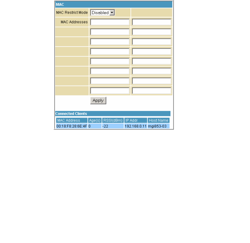
This document is uncontrolled pending incorporation in PDM
9 SVG2500 WIRELESS PAGES
100
Wireless 802.11b/g Access Control Page
This page allows you to configure the Access Control to the AP as well as status on
the connected clients.
Field Description
MAC Restrict Mode Selects whether wireless clients with the specified MAC address
are allowed or denied wireless access.
Select Disabled to allow all clients.
MAC Address A list of wireless client MAC addresses to allow or deny based on
the Restrict Mode setting. Valid input MAC address formats are
XX:XX:XX:XX:XX:XX and XX-XX-XX-XX-XX-XX.
Connected Clients A list of connected wireless clients. When a client connects
(associates) to the network, it is added to the list; when a client
leaves (disassociates) from the network, it is removed from the list.
For each client, the age (in seconds), estimated average receive
signal strength (in dBm), IP address, and host name are presented.
The age is the amount of time elapsed since data was transmitted
to or received from the client.
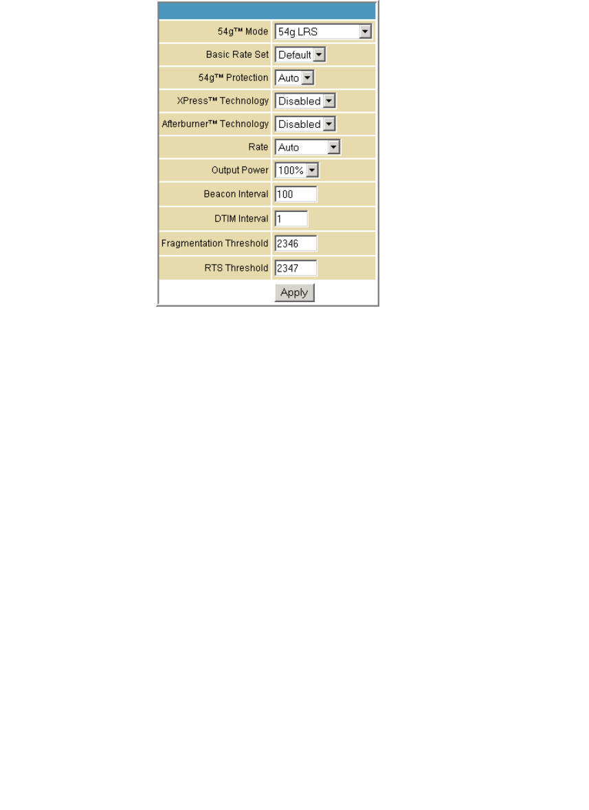
This document is uncontrolled pending incorporation in PDM
9 SVG2500 WIRELESS PAGES
101
Wireless 802.11b/g Advanced Page
This page allows you to configure data rates and WiFi thresholds.
Field Description
54g™ Mode Sets these network modes:
54g Auto
54g Performance
54g LRS
802.11b only
54g Auto accepts 54g, 802.11g, and 802.11b clients, but optimizes
performance based on the type of connected clients. 54g
Performance accepts only 54g clients and provides the highest
throughout; nearby 802.11b networks may have degraded
performance. 54g LRS interoperates with the widest variety of
54g, 802.11g, and 802.11b clients. 80211b. accepts only 802.11b
clients.
Basic Rate Set Determines which rates are advertised as "basic" rates. Default
uses the driver defaults. All sets all available rates as basic rates.
54g™ Protection In Auto mode, the AP will use RTS/CTS protection to improve
802.11g performance in mixed 802.11g + 802.11b networks. Turn
protection off to maximize 802.11g throughput under most
conditions.
XPress™ Technology This is a performance-enhancing Wi-Fi technology designed for
increasing throughput and efficiency. It is used when there are
mixed wireless networks in the surrounding area from 802.11a/b/g
networks.
Afterburner™ Technology This is also a performance-enhancing Wi-Fi technology that
enhances the existing 802.11g standard by increasing throughput
by 40 percent.
Rate Forces the transmission rate for the AP to a particular speed.
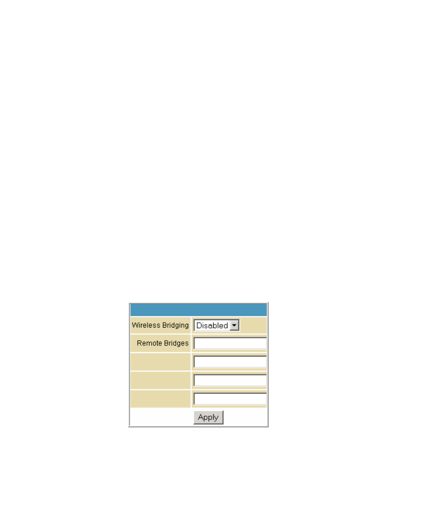
This document is uncontrolled pending incorporation in PDM
9 SVG2500 WIRELESS PAGES
102
Field Description
Auto will provide the best performance in nearly all situations.
Output Power Sets the output power as a percentage of the hardware's
maximum capability.
Beacon Interval Sets the beacon interval for the AP. The default is 100, which is
fine for nearly all applications.
DTIM Interval Sets the wakeup interval for clients in power save mode. When a
client is running in power save mode, lower SVG2500N-2.1.1.0-
LAB-00-SH.bin values provide higher performance but result in
decreased client battery life, while higher values provide lower
performance but result in increased client battery life.
Fragmentation Threshold Sets the fragmentation threshold. Packets exceeding this
threshold will be fragmented into packets no larger than the
threshold before packet transmission.
RTS Threshold Sets the RTS threshold. Packets exceeding this threshold will
cause the AP to perform an RTS/CTS exchange to reserve the
wireless medium before packet transmission.
Wireless Bridging Page
This page allows you to configure the WDS features.
Field Description
Wireless Bridging Enables or disables wireless bridging.
Remote Bridges Table of remote bridge MAC addresses authorized to establish a
wireless bridge. Up to four remote bridges may be connected.
Typically, you will also have to enter your AP's MAC address on the
remote bridge.
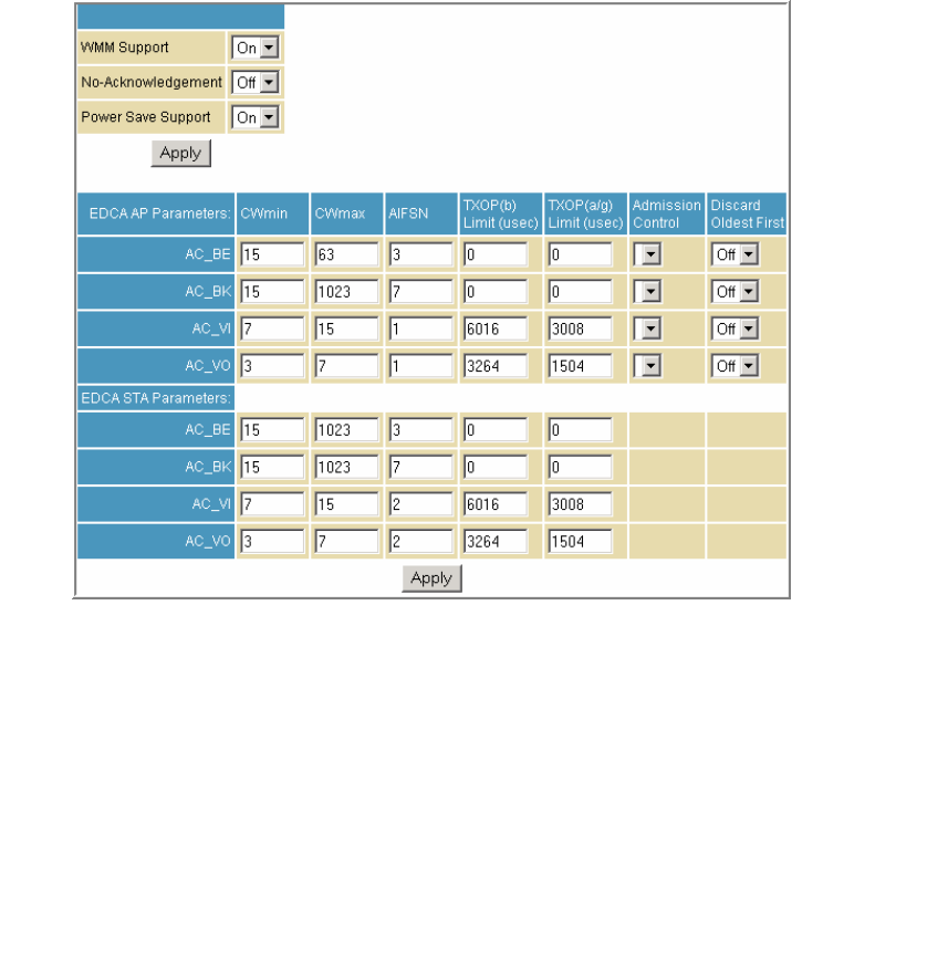
This document is uncontrolled pending incorporation in PDM
9 SVG2500 WIRELESS PAGES
103
Wireless 802.11b/g Wi-Fi Multimedia Page
This page allows you to configure the Wi-Fi Multimedia Quality of Service (QoS).
Field Description
WMM Support Sets WMM support to Auto, On, or Off.
If enabled (Auto or On), the WME Information Element is
included in beacon frame.
No-Acknowledgement Sets No-Acknowledgement support to On or Off.
When enabled, acknowledgments for data are not transmitted.
Power Save Support Sets Power Save support to On or Off.
When Power Save is enabled, the AP queues packets for STAs
that are in power-save mode. Queued packets are transmitted
when the STA notifies AP that it has left power-save mode.

This document is uncontrolled pending incorporation in PDM
9 SVG2500 WIRELESS PAGES
104
Field Description
EDCA AP Parameters Specifies the transmit parameters for traffic transmitted from the
AP to the STA in four Access Categories:
• Best Effort (AC_BE)
• Background (AC_BK)
• Video (AC_VI)
• Voice (AC_VO)
Transmit parameters include Contention Window (CWmin and
CWmax), Arbitration Inter Frame Spacing Number (AIFSN), and
Transmit Opportunity Limit (TXOP Limit).
There are also two AP-specific settings: Admission Control and
Discard Oldest First. Admission control specifies if admission
control is enforced for the Access Categories. Discard Oldest
First specifies the discard policy for the queues. On discards the
oldest first; Off discards the newest first.
EDCA STA Parameters Specifies the transmit parameters for traffic transmitted from the
STA to the AP in four Access Categories:
• Best Effort (AC_BE)
• Background (AC_BK)
• Video (AC_VI)
• Voice (AC_VO)
Transmit parameters include Contention Window (CWmin and
CWmax), Arbitration Inter Frame Spacing Number (AIFSN), and
Transmit Opportunity Limit (TXOP Limit).
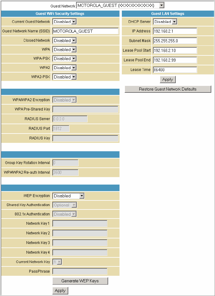
This document is uncontrolled pending incorporation in PDM
9 SVG2500 WIRELESS PAGES
105
Wireless 802.11b/g Guest Network Page
This page allows you to configure a secondary guest network on the wireless interface. This
network is isolated from the LAN. Any clients that associate with the guest network SSID
will be isolated from the private LAN and can only communicate with WAN hosts.

This document is uncontrolled pending incorporation in PDM
9 SVG2500 WIRELESS PAGES
106
Field Description
Guest Network You may have several different wireless Guest Networks running
with different options. This field lets you select which wireless Guest
Network you want to modify.
Current Guest Network When set to Enabled, beacon frames are transmitted with the Guest
SSID
Guest Network Name (SSID) Assigns a unique network name (SSID) for the guest network, which
appears in the beacon frames.
Closed Network With a closed network, users type the SSID into the client application
instead of selecting the SSID from a list.
This feature makes it slightly more difficult for the user to gain
access.
DHCP Server Enables the DHCP server to give out leases to guest network clients
from the specified lease pool. If the DHCP server is disabled, guest
network STAs need to be assigned static IP addresses.
IP Address Specifies the gateway IP relayed to guest clients in DHCP lease
offers.
Subnet Mask Specifies the subnet mask for the guest network.
Lease Pool Start Specifies the starting IP address for the guest network lease pool.
Lease Pool End Specifies the ending IP address for the guest network lease pool.
Lease Time Specifies the lease time for the guest network lease pool once the
Configuration Manager completes the WAN provisioning.
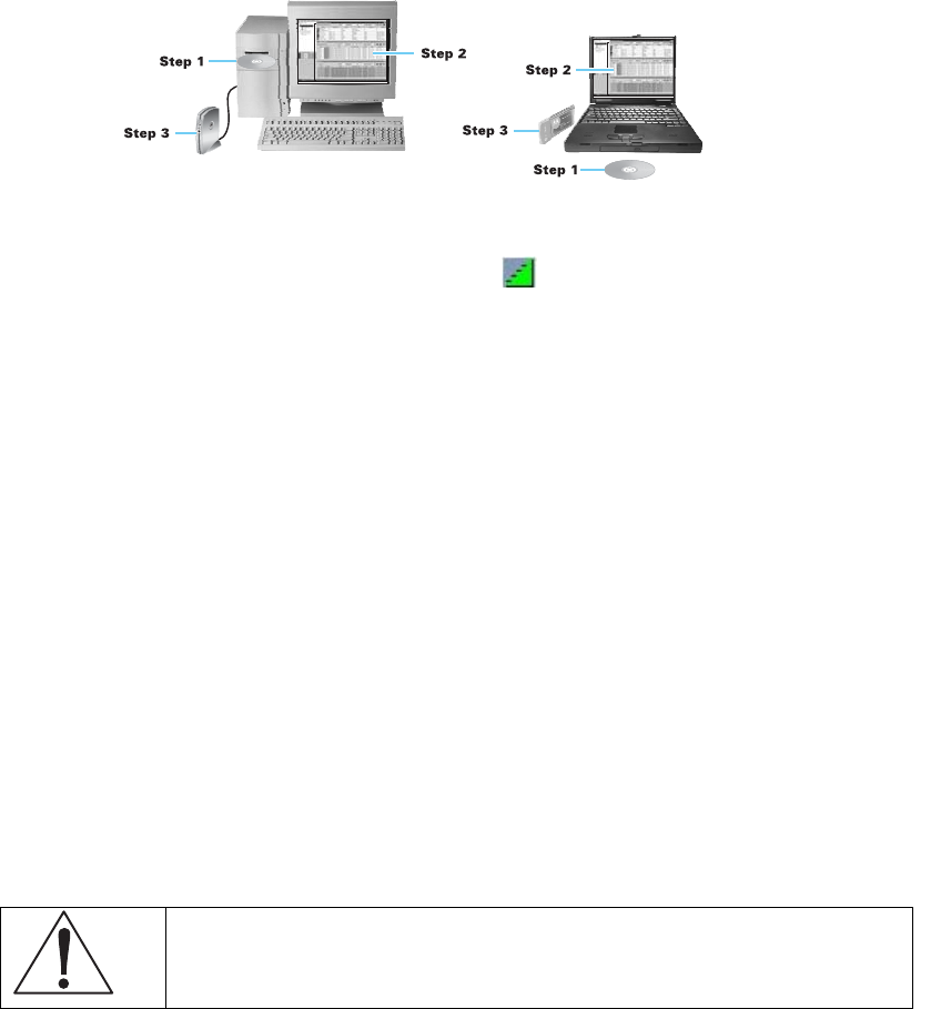
This document is uncontrolled pending incorporation in PDM
9 SVG2500 WIRELESS PAGES
107
Configuring the Wireless Clients
For each wireless client computer (station), install the wireless adapter by following the
instructions supplied with the adapter. Be sure to:
1. Insert the CD-ROM for the adapter in the CD-ROM drive on the client.
2. Install the device software from the CD.
3. Insert the adapter in the PCMCIA or PCI slot or connect it to the USB port.
Configure the adapter to obtain an IP address automatically.
On a PC with Wireless Client Manager installed, the icon is displayed on the Windows
task bar. Double-click the icon to launch the utility. You may need to do the following to use a
wireless client computer to access the Internet:
If You Performed On Each Client, You Need to Perform
Configuring WPA on the SVG2500 Configuring a Wireless Client for WPA or WPA2
Configuring WEP on the SVG2500 Configuring a Wireless Client for WEP
Configuring the Wireless Network Name
on the SVG2500
Configuring a Wireless Client with the Network Name
(SSID)
Configuring a MAC Access Control List
on the SVG2500
No configuration on client required
Configuring a Wireless Client for WPA
If you enabled WPA and set a PSK Passphrase by configuring WPA on the SVG2500,
you must configure the same passphrase (key) on each wireless client. The SVG2500
cannot authenticate a client if:
• WPA is enabled on the SVG2500 but not on the client
• The client passphrase does not match the SVG2500 PSK Passphrase
Caution!
Never provide the PSK Passphrase to anyone who is not authorized to use your
WLAN.

This document is uncontrolled pending incorporation in PDM
9 SVG2500 WIRELESS PAGES
108
Configuring a Wireless Client for WEP
If you enabled WEP and set a key by configuring WEP on the SVG2500, you must
configure the same WEP key on each wireless client. The SVG2500 cannot
authenticate a client if:
• Shared Key Authentication is enabled on the SVG2500 but not on the client
• The client WEP key does not match the SVG2500 WEP key
For all wireless adapters, you must enter the 64-bit or 128-bit WEP key generated by
the SVG2500.
Caution!
Never provide the WEP key to anyone who is not authorized to use your WLAN.
Configuring a Wireless Client with the Network Name (SSID)
After you specify the network name on the Wireless Basic Page, many wireless
cards or adapters automatically scan for an access point such as the SVG2500 and
the proper channel and data rate. If your card requires you to manually start scanning
for an access point, do so following the instructions in the documentation supplied
with the card. You must enter the same SSID in the wireless configuration setup for
the device to communicate with the SVG2500.
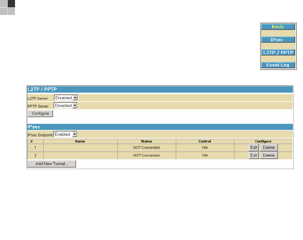
This document is uncontrolled pending incorporation in PDM
109
10 SVG2500 VPN PAGES
The VPN pages allow you to configure and manage VPN tunnels.
You can click any VPN submenu option to view or change the
configuration information for that option.
VPN Basic Page
This page allows you to enable VPN protocols and manage VPN tunnels.
Field Description
L2TP Server Enable or disable the Layer 2 Tunneling Protocol
PPTP Server Enable or disable the Point-to-Point Protocol
IPsec Endpoint Enable or disable the Internet Protocol Security protocol
Add New Tunnel Creates a new tunnel configuration and appends it to the table.
Click Edit to add the name and constructs of the tunnel for that tunnel.
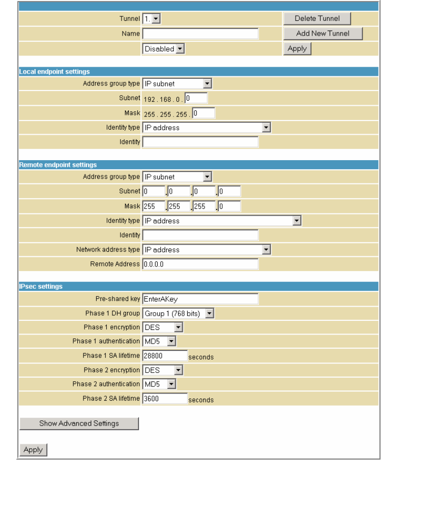
This document is uncontrolled pending incorporation in PDM
10 SVG2500 VPN PAGES
110
VPN IPsec Page
This page allows you to configure multiple VPN tunnels to various client PCs. You can
configure and store different tunnels, but you cannot enable them for ease of use
with connections and/or client PCs that are not constantly used.
For each tunnel configuration you store, its unique IPsec parameters are stored
using the IPsec Settings section at the bottom of the page. You can click Show
Advanced Settings at the bottom of the page to display the advanced features that
control IPSEC key management and negotiation with the far endpoint.
Field Description
Tunnel Contains preset tunnels by their preset name. This allows you to
configure each tunnel individually.

This document is uncontrolled pending incorporation in PDM
10 SVG2500 VPN PAGES
111
Field Description
Name A generic user-specified name for a group of settings for a single
tunnel.
Once the appropriate tunnel name is entered for the first time, click
Add New Tunnel to create a heading for the tunnel settings selected
from the Tunnel drop-down list. If no name is entered here, the
tunnels are sequentially named 1, 2, 3, and so on.
Enable drop-down Once a particular VPN tunnel is named and configured, it can be
left stored and disabled or enabled via the Enable/Disable drop-
down list. Click Apply to make the "Enable/Disable" setting effective.
Local Endpoint Settings
Address group type Set the local VPN access group as one of the following group
types:
• Single IP address – for one computer, enter the IP address
for the specific computer
• IP address range – for a small range of computers, enter the
starting and ending IP addresses for the group of consecutive
IP address that will have access to the VPN tunnel
• IP Subnet – for an entire subnet/network, enter the Subnet
and Mask
For IP address range and IP Subnet enter the starting and ending IP
addresses for the group of consecutive IP address that will have
access to the VPN tunnel.
Identity Type You can define the local endpoint identity type to automatically use
the WAN IP address of the router or as a user-specified IP address,
fully qualified domain name (FQDN), or e-mail address. This is the
identity that the far endpoint will use for identification of the VPN
termination point and handshake.
The remote VPN endpoint on the other side of the tunnel should
match the settings here for its remote endpoint settings.
Identity Once the identity type is selected, enter the identity string here.
• For IP address, enter x.x.x.x.
• For FQDN, enter yourdomain.com
• For email address identity, enter yourname@yourdomain.com
The remote VPN endpoint on the other side of the tunnel should
match the settings here for its remote endpoint settings.

This document is uncontrolled pending incorporation in PDM
10 SVG2500 VPN PAGES
112
Field Description
Remote Endpoint Settings
Address group type Set the remote VPN access group to one of the following group
types:
• Single IP address – for one computer, enter the IP address
for the specific computer
• IP address range – for a small range of computers, enter the
starting and ending IP addresses for the group of consecutive
IP address that will have access to the VPN tunnel.
• IP Subnet – for an entire subnet/network, enter the Subnet
and Mask
For IP address range and IP Subnet enter the starting and ending IP
addresses for the group of consecutive IP address that will have
access to the VPN tunnel.
The remote VPN endpoint on the other side of the tunnel should
match the settings here for its local endpoint settings.
Identity type You can define the remote endpoint identity type to automatically
use the remote endpoint IP address or as a user specified IP
address, fully qualified domain name (FQDN), or e-mail address.
This is the identity that the far endpoint will use for identification of
the VPN termination point and handshake.
The remote VPN endpoint on the other side of the tunnel should
match the settings here for its local endpoint settings.
Identity Once the identity type is selected, enter the identity string here.
• For IP address, enter x.x.x.x.
• For FQDN, enter yourdomain.com
• For email address identity, enter yourname@yourdomain.com
The remote VPN endpoint on the other side of the tunnel should
match the settings here for its local endpoint settings.
Network address
type
Select the remote endpoint's WAN address type: IP address or
Fully Qualified Domain Name (FQDN)
Remote Address Enter either the IP address of the remote endpoint or its FQDN.

This document is uncontrolled pending incorporation in PDM
10 SVG2500 VPN PAGES
113
Field Description
IPsec Settings With VPN tunnels, there are two phases of Security Association
(SA). Phase 1 is used to create an IKE SA. After Phase 1 is
completed, Phase 2 is used to create one or more IPSEC SAs,
which are then used to key IPSEC sessions.
Pre-shared key If one side of the VPN tunnel is using a unique firewall identifier (or
Pre-shared Key), the firewall identifier or Pre-shared Key should be
entered in the "Pre-shared Key" field.
Phase 1 DH group There are three Diffie-Hellman groups to choose from: 768 bits,
1024 bits, and 1536 bits.
Diffie-Hellman is a cryptographic technique that uses public and
private keys for encryption and decryption. The higher number of
bits selected from the options list the more secure the encryption.
Options: Group 1 (768 bits), Group 2 (1024 bits), or
Group 5 (1536 bits).
Phase 1 encryption Encryption is used to secure the VPN connection between
endpoints. Five different types of encryption are available: DES,
3DES, AES-128, AES-192, and AES-256. Any form off encryption
may be selected as long as the far endpoint matches. One of the
more common settings here is 3DES; however, AES is also a very
strong encryption method.
Phase 1 authentication Authentication acts as another level of security. The two types of
authentication available are MD5 and SHA. SHA is recommended
because it is more secure. Either authentication type may be used
as long as the other end of the VPN tunnel uses the same method.
Phase 1 SA lifetime Specifies the lifetime of individual rotating keys.
Enter the desired number of seconds for the key to last until a re-
key negotiation between each endpoint is negotiated. The default
setting is 28,800 seconds.
A smaller lifetime is generally more secure, since it would give an
attacker a smaller amount of time to try to crack the key, but key
negotiation does take up bandwidth, so network throughput will be
sacrificed with small lifetimes. Entries here are typically in the
thousands or tens of thousands of seconds.
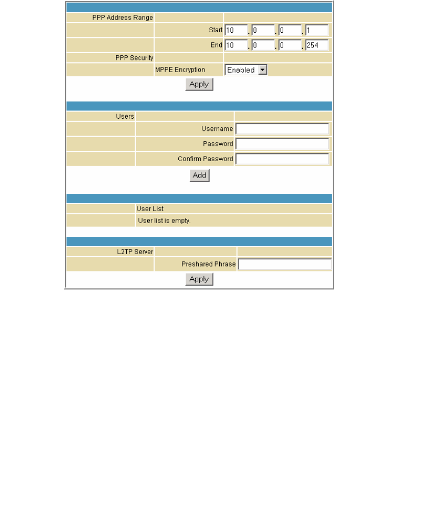
This document is uncontrolled pending incorporation in PDM
10 SVG2500 VPN PAGES
114
VPN L2TP/PPTP Page
This page allows configuration of L2TP and PPTP server options.
Field Description
PPP Address Range
Start
End
Specify the starting and ending IP address range so that when the
tunnel is set up, the client and server side will get their IP address
from this specified range.
PPP Security
MPPE Encryption
Microsoft Point to Point Encryption (MPPE) is a type of link encryption
used in PPTP. Link encryption means that the data sent along this
tunnel will be encrypted.
You can choose to enable or disable MPPE encryption.
Username Used to authenticate between the client and the server of the tunnel
that was created between them.
Password Enter a user password for authentication.
Confirm Password Enter the password again for confirmation.
Preshared Phrase Pre shared Phrase – A phrase used to authenticate when the
SVG2500 is acting as a Layer 2 Tunneling Protocol (L2TP) server.
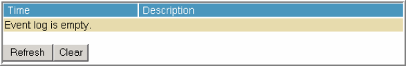
This document is uncontrolled pending incorporation in PDM
10 SVG2500 VPN PAGES
115
VPN Event Log Page
This page allows you to view the VPN Event Log. It shows a history of VPN
connections and activity in chronological order and shows the IP address of both
endpoints on the tunnel (remote and local).
Click Refresh to update the Event Log table to show any changes since the web page
was last loaded.
Click Clear to clear the log table of its current contents and only the most recent data
will appear.
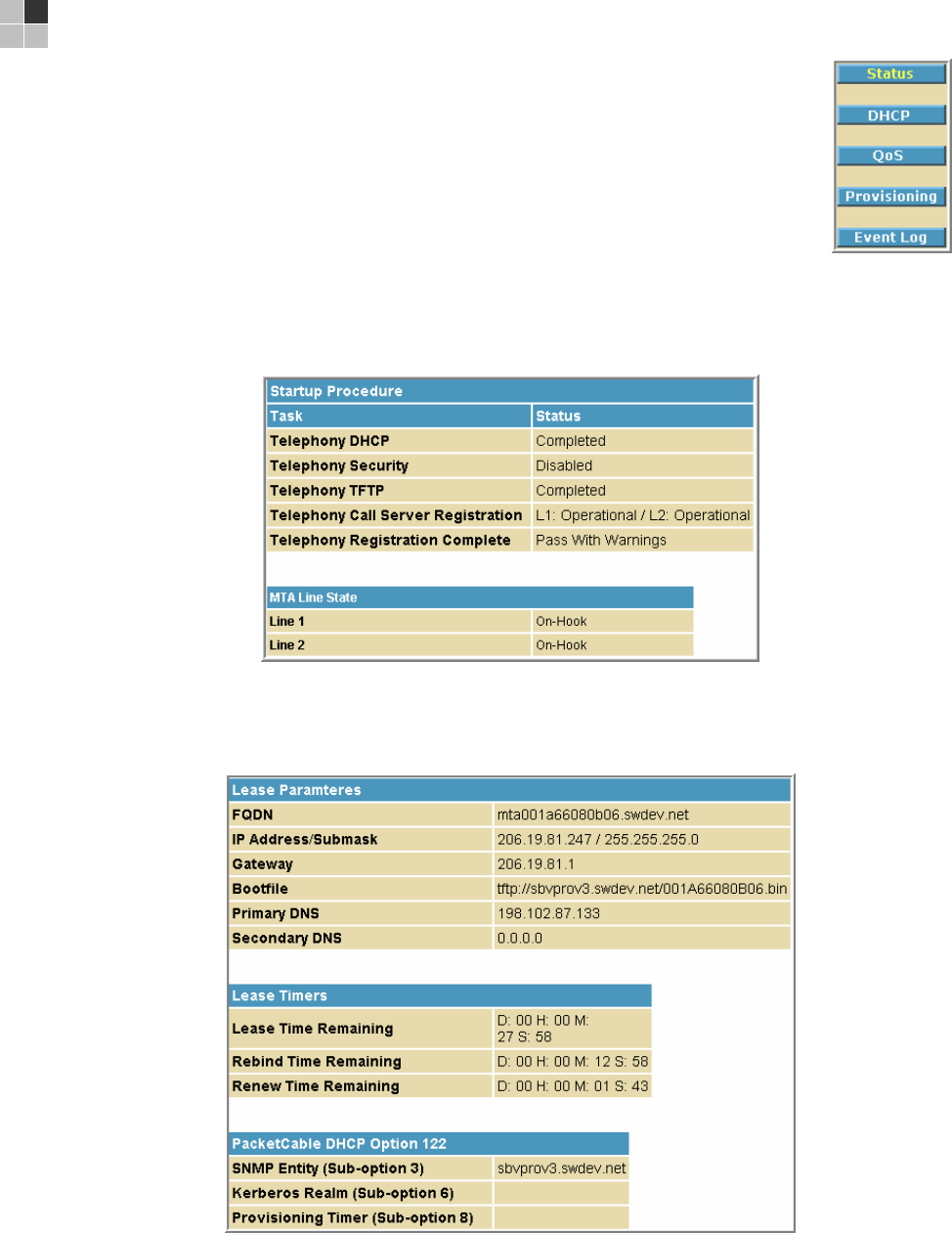
This document is uncontrolled pending incorporation in PDM
117
11 SVG2500 MTA PAGES
The Multimedia Terminal Adapter (MTA) in your SVG2500 provides
digital Voice over IP (VoIP) services, which allow you to use the
Internet to make telephone calls. Basic telephone functions such as
call waiting, three-way calling, voice mail, and fax transmissions are
supported with this connection on the SVG2500.
You can click any MTA submenu option to view the status information
for that option.
MTA Status Page
This page displays the initialization status of the MTA.
MTA DHCP Page
This page displays the MTA DHCP lease information.
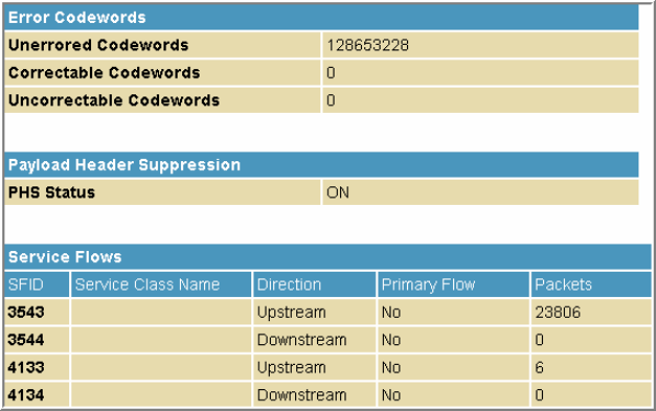
This document is uncontrolled pending incorporation in PDM
11 SVG2500 MTA PAGES
118
MTA QoS Page
This page displays the MTA Quality of Service (QoS) parameters.
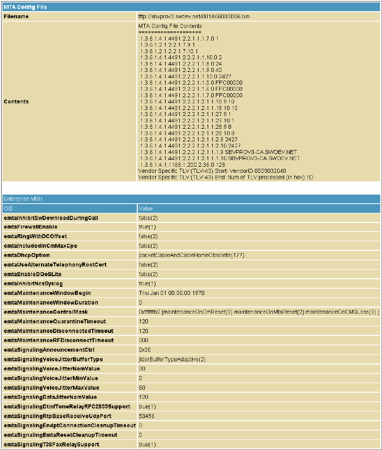
This document is uncontrolled pending incorporation in PDM
11 SVG2500 MTA PAGES
119
MTA Provisioning Page
This page displays the MTA provisioning details about your SVG2500 VoIP telephone
connection.
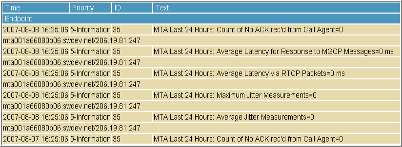
This document is uncontrolled pending incorporation in PDM
11 SVG2500 MTA PAGES
120
MTA Event Log
This page displays the MTA Event Log information related to your SVG2500 VoIP
telephone connection. Diagnostic messages generated by the MTA are provided.
This information is intended for use by a qualified technician.
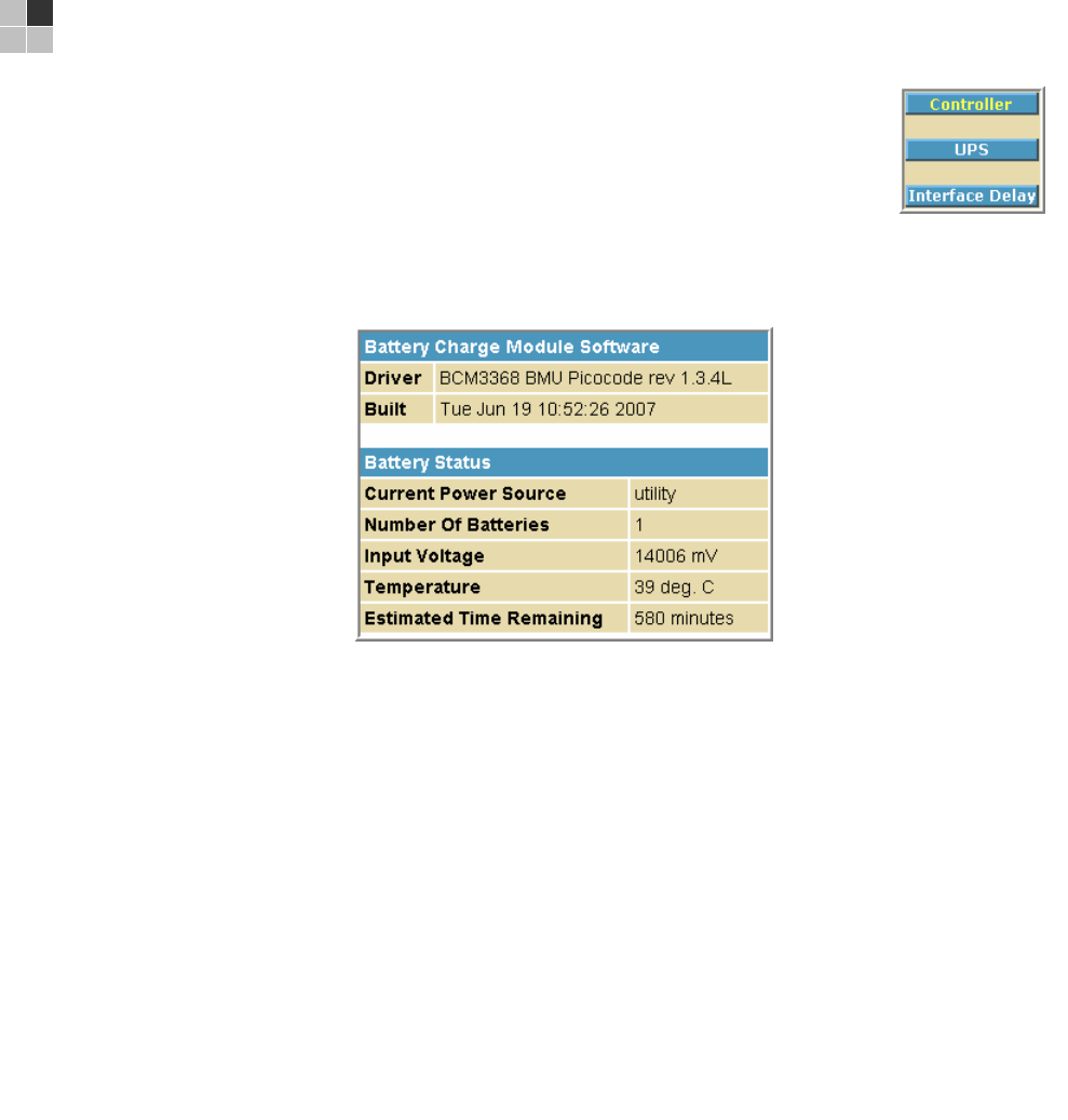
This document is uncontrolled pending incorporation in PDM
121
12 SVG2500 BATTERY PAGES
The Battery pages show varying status information on the batteries
installed in the SVG2500.
You can click any Battery submenu option to view the status
information for that option.
Battery Controller Page
This page displays the status of the SVG2500 battery controller.
Field Description
Driver Shows the Revision Level of the PICO microcode. The PICO is the
module within the BCM3368 that is responsible for managing the
battery charge and discharge circuitry.
Built Shows the date and time of the build of the PICO microcode in use
by the unit.
Current Power Source Shows the active power source for the unit as utility (when operating
on AC) or battery.
Number of Batteries Shows the number of batteries currently installed in the battery pack.
Input Voltage Shows the current voltage (mV) being supplied to the unit by the
active power source.
Temperature Shows the current internal temperature (degrees Celsius) of the unit
as measured by the temperature-sensing resistor
Estimated Time Remaining Shows the estimated time until the battery power is depleted
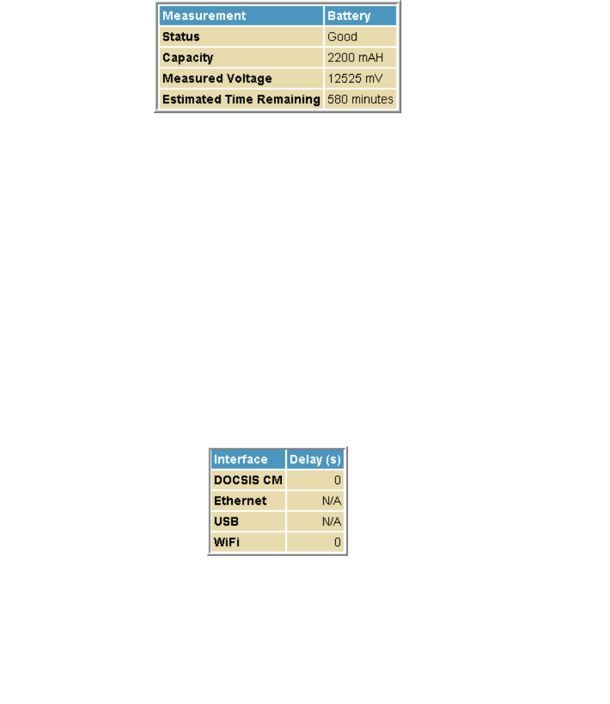
This document is uncontrolled pending incorporation in PDM
12 SVG2500 BATTERY PAGES
122
Battery UPS Page
This page displays the status of the individual batteries.
Field Description
Status Shows whether Battery A and/or Battery B are currently installed in the
battery pack. Note that some units are only capable of supporting
Battery A.
Capacity Shows a measure of each installed battery's total capacity in milliamp
hours. For example, 2200 mAH capacity means the battery can deliver
2200 mA for 1 hour.
Measured Voltage Shows the voltage (mV) each installed battery is currently capable of
delivering.
Estimated Time
Remaining
Shows the estimated time until the battery power for each installed
battery is depleted.
Battery Interface Delay Page
This page displays the shutdown delay for the various user interfaces when
switching to battery power. N/A indicates that the interface will not be shut down.
Field Description
Interface Identifies the components of the unit that are subject to deactivation
when the unit is operating on battery power.
Delay(s) For each component shown under Interface, the corresponding Delay
fields show the elapsed time for each component before the component
is automatically deactivated following a shift to battery power. Note that
N/A indicates that the component will not be deactivated.

This document is uncontrolled pending incorporation in PDM
123
13 TROUBLESHOOTING
Solutions
If the solutions listed here do not solve your problem, contact your service provider. Before
calling your service provider, try pressing the reset button on the rear panel of the SVG2500.
Resetting the SVG2500 may take 5 to 30 minutes. Your service provider may ask for the
status of the lights as described in Front-Panel Lights and Error Conditions.
Problem Possible Solution
Power light is off Check that the SVG2500 is properly plugged into the electrical outlet.
Check that the electrical outlet is working.
Press the Reset button.
Cannot send or
receive data
On the top front panel, note which is the first light that is off. This light
indicates where the error occurred as described in Front-Panel Lights and
Error Conditions. If you have cable TV, check that the TV is working and the
picture is clear. If you cannot receive regular TV channels, the data service
and VoIP telephone service will not function.
Check the coaxial cable at the SVG2500 and wall outlet. Hand-tighten if
necessary.
Check the IP address. Follow the steps for verifying the IP address for
your system. See Configuring TCP/IP. Call your service provider if you
need an IP address.
Check that the Ethernet cable is properly connected to the SVG2500 and
the computer.
Problems related to
unsuccessful USB driver
installation
Remove the USB driver. Follow the appropriate procedure for your system
in Installing USB Drivers.
A wireless client(s)
cannot send or receive
data
Perform the first four checks in “Cannot send or receive data.”
Check the Security Mode setting on the Wireless Security Page:
• If you enabled WPA and configured a passphrase on the SVG2500, be
sure each affected wireless client has the identical passphrase. If this
does not solve the problem, check whether the wireless client supports
WPA.
• If you enabled WEP and configured a key on the SVG2500, be sure each
affected wireless client has the identical WEP key. If this does not solve
the problem, check whether the client wireless adapter supports the type
of WEP key configured on the SVG2500.
• To temporarily eliminate the Security Mode as a potential issue, disable
security.
After resolving your problem, be sure to re-enable wireless security.
On the Wireless Basic Page:
• Check whether you turned on Disable SSID Broadcast. If it is on, be
sure the network name (SSID) on each affected wireless client is identical
to the SSID on the SVG2500.
• On the Wireless Access Control Page, be sure the MAC address for
each affected wireless client is correctly listed.
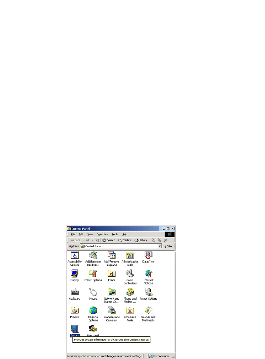
This document is uncontrolled pending incorporation in PDM
13 TROUBLESHOOTING
124
Problem Possible Solution
Slow wireless
transmission speed with
WPA enabled
On the Wireless Security Page, check whether the WPA Encryption type
is TKIP. If all of your wireless clients support AES, change the WPA
Encryption to AES.
Front-Panel Lights and Error Conditions
Light Turns Off During Startup If Turns Off During Normal Operation If
DS The downstream receive channel cannot be
acquired
The downstream channel is lost
US The upstream send channel cannot be
acquired
The upstream channel is lost
ONLINE IP registration is unsuccessful The IP registration is lost
POWER The SVG2500 is not properly plugged into the
power outlet
The SVG2500 is unplugged
Removing USB Drivers
Removing the USB Driver in Windows 2000
Although your SVG model number may be different than in the images in this guide,
the procedure is the same.
1. Select Control Panel from either the Windows Start menu or Windows Desktop
to display the Control Panel window.
2. Double-click System to display the System Properties window.
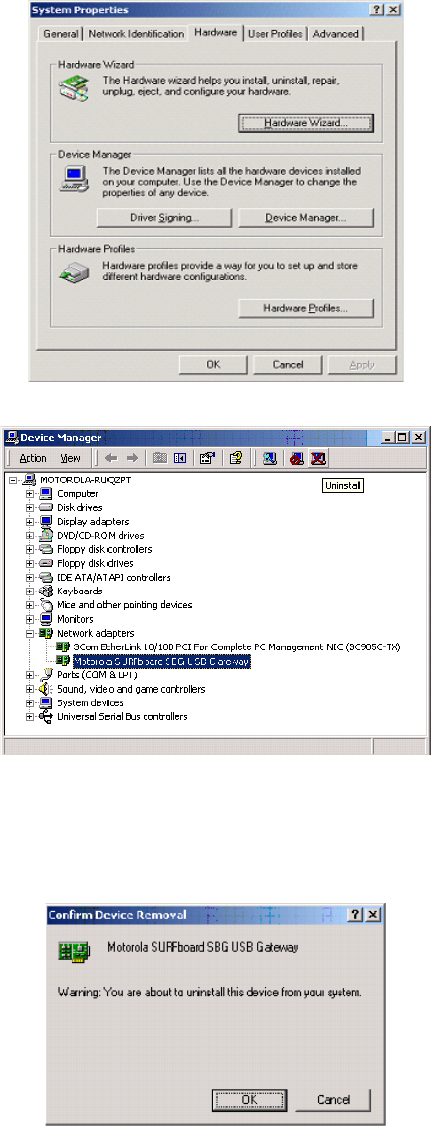
This document is uncontrolled pending incorporation in PDM
13 TROUBLESHOOTING
125
3. Click the Hardware tab.
4. Click Device Manager to display the Device Manager window:
5. Double-click Network Adapters to expand the list.
6. Click Motorola USB SVG Modem. The Uninstall icon displays on the menu bar at the
top of the window.
7. Click the Uninstall icon. The Confirm Device Removal window is displayed:
8. Click OK to close the Device Manager window.
9. Close the Control Panel window.
This document is uncontrolled pending incorporation in PDM
13 TROUBLESHOOTING
126
10. To continue, perform Running the Motorola USB Driver Removal Utility.
Removing the USB Driver in Windows XP
1. Select Control Panel from either the Windows Start menu or Windows Desktop
to display the Control Panel window.
2. If a Category view similar to the image under step 2 is displayed, click Performance
and Maintenance to display the Performance and Maintenance window. Otherwise,
skip to step 5.
3. Click System to display the System Properties window. Skip to step 6.
4. If a Classic view similar to the following is displayed, double-click System to
display the System Properties window:
5. Click the Hardware tab to display the Hardware page.
6. Click the Device Manager button to display the Device Manager window:
7. Double-click Network adapters.
8. Click the Motorola USB SVG Modem. The Uninstall icon displays on the window
near the top.
9. Click the Uninstall icon.
10. Close the Device Manager and Control Panel windows.
11. Perform Running the Motorola USB Driver Removal Utility.
Running the Motorola USB Driver Removal Utility
Before running the Motorola USB Driver Removal Utility, perform one of the
following to run the Windows Device Manager:
• Removing the USB Driver in Windows 2000
• Removing the USB Driver in Windows XP
To run the Motorola USB Driver Removal Utility:
1. Insert the SVG2500 Installation CD-ROM in the CD-ROM drive. After a short
time, a window with language choices is displayed.
2. Press Esc on the keyboard to exit the start-up screens.
3. To start Windows Explorer, click Start and select Run.
4. On the Run window, type explorer and click OK.
5. Your Windows Explorer may appear different than in the image on this page.
There are variations between Windows versions and you can configure Windows
Explorer as you like.
6. Double-click My Computer.
7. Double-click the Motorola SVG icon (D: in the image).
This document is uncontrolled pending incorporation in PDM
13 TROUBLESHOOTING
127
8. Double-click remove or remove.exe to run the Remove utility from the SVG2500
Installation CD-ROM. The Motorola USB Driver Removal window is displayed. Be
sure the USB cable is disconnected.
9. Click Remove Driver. A progress bar indicates that the driver is being removed.
10. Click Exit to exit the Motorola USB Driver Removal Utility.
or
Click Details to display informational messages about the files that were found
and deleted similar to the ones shown below. If necessary, scroll down to view
the entire list. Click OK to close the details window.
11. Re-install the USB driver following one of the options listed below:
• Setting Up the USB Driver in Windows 2000
• Setting Up the USB Driver in Windows XP
12. If you continue to have problems, contact your Internet provider.

This document is uncontrolled pending incorporation in PDM
129
14 CONTACT US
If you need assistance while working with the SVG2500, contact your Internet Service
provider.
For information about customer service, technical support, or warranty claims, see the
Motorola Regulatory, Safety, Software License, and Warranty Information card provided with
the SVG2500.
For answers to typical questions, see Frequently Asked Questions.
For more information about Motorola consumer Connected Home Solutions products,
education, and support, visit broadband.motorola.com/consumers.
For more information about Motorola consumer Connected Home Solutions products,
education, and support, visit http://broadband.motorola.com/consumers/support/default.asp.

This document is uncontrolled pending incorporation in PDM
131
15 FREQUENTLY ASKED QUESTIONS
Here are answers to questions our customers frequently ask:
Q What is high-speed cable Internet access?
A Cable Internet access uses cable television wires instead of telephone lines to
connect to the Internet. It is extremely fast and does not tie up telephone lines for
incoming or outgoing calls and faxes.
Q How fast is the Motorola SVG2500 SURFboard Wireless Voice Gateway?
A Cable modems offer Internet access at speeds up to 100 times faster than a
traditional phone modem. You can experience speeds of over 1,000 Kbps. Network
condition such as traffic volume and the speed of the sites you visit can affect
download speeds.
Q How many users can one SVG2500 support?
A A single SVG2500 can support up to 245 users, each assigned a unique IP
address, on a Class C network.
Q What is Network Address Translation?
A NAT is a technique to translate private IP addresses on your LAN to a single IP
address assigned by your service provider that is visible to outside users on the
Internet.
Q What are IEEE 802.11g and IEEE 802.11b?
A They are IEEE wireless network standards.
Q What type of firewall is provided on the SVG2500?
A The SVG2500 provides a stateful-inspection firewall. For more information, see
Section 7, SVG2500 Firewall Pages.
Q What wireless security measures are provided on the SVG2500?
A To protect data transmitted over wireless connections, the SVG2500 supports
WPA or WEP encryption and MAC access control lists. For information, see Setting
Up Your Wireless LAN.
Q Why is there no Standby button?
A As a security measure, some Motorola cable modems provide a Standby button to
temporarily suspend the Internet connection. Because enabling the SVG2500
firewall provides high security levels while connected, the Standby button is not
required.
This document is uncontrolled pending incorporation in PDM
15 FREQUENTLY ASKED QUESTIONS
132
Q Can I still watch cable TV while using my SVG2500?
A Yes, your cable TV line can carry the TV signal while you send and receive
information on the Internet.
Q What are CableLabs Certified, DOCSIS, and Euro-DOCSIS?
A CableLabs Certified, DOCSIS, and Euro-DOCSIS are the industry standards for
high-speed data distribution over cable television system networks. They are
intended to ensure that all compliant cable modems interface with all compliant
cable systems. Your SVG2500 is DOCSIS or Euro-DOCSIS certified.
Q If I have an SVG2500, can I still use my old 28.8 Kbps or 56 Kbps modem?
A Yes you can. However, once you’ve experienced the speed of cable Internet
access, you’ll never again want to wait for traditional dial-up services.
Q Do I need to subscribe to cable TV to get cable Internet access?
A No, but you will need to subscribe to cable Internet service. Some systems
require that you subscribe to basic service before you can get Internet access and/or
offer a discount when you use your own SVG2500. Check with your local cable
company for specific information.
Q What type of technical support is available?
A For questions about your Internet service, connection, or SVG2500, call your
Internet service provider.
Q What do I do if my SVG2500 stops working?
A Troubleshooting provides tips to diagnose problems and simple solutions. If you
continue to have problems, call your Internet service provider.
Q Can multiple game players on the SVG2500 LAN log onto the same game server
and play simultaneously with just one public IP address?
A It depends on the game server. For more information about gaming, see Gaming
Configuration Guidelines.

This document is uncontrolled pending incorporation in PDM
133
16 SPECIFICATIONS
GENERAL
Standards
Cable Interface
Network Interface
Wireless Interface
Dimensions
(w/o antenna)
Interoperates with DOCSIS and Euro-DOCSIS 2.0/1.1 and PacketCable
and Euro-PacketCable 1.5/1.0 (SIP and CableHome 1.1 optional)
F-connector, female, 75 Ω
One USB, four 10/100 Ethernet ports
802.11b/g Wi-Fi
26.7 cm L x 18.41 cm W x 5.72 cm H
(10.50 in x 7.25 in x 2.25 in)
INPUT POWER
North America
Outside North America
105 to 125 VAC, 60 Hz
100 to 240 VAC, 50 to 60 Hz
ENVIRONMENT
Operating Temperature
Storage Temperature
Operating Humidity
0 °C to 40 °C (32 °F to 104 °F)
–30 °C to 80 °C (–22 °F to 176 °F)
0 to 95% R.H. (non-condensing)
DOWNSTREAM
Modulation
Maximum Data Rate*
Bandwidth
Symbol Rates
Operating Level Range
Frequency Range
Input Impedance
64 or 256 QAM
38 Mbps (256 QAM at 5.361 Msym/s)
6 MHz
64 QAM at 5.069 Msym/s, 256 QAM at 5.361 Msym/s
–15 to 15 dBmV
88 to 860 MHz
75 Ω (nominal)

This document is uncontrolled pending incorporation in PDM
16 SPECIFICATIONS
134
UPSTREAM
Modulation
Maximum Channel Rate
Bandwidth
Symbol Rates
Operating Level Range
A-TDMA
S-CDMA
Output Impedance
Frequency Range
8***, 16, 32***, 64***,128*** QAM or QPSK
30 Mbps**
200 kHz, 400 kHz, 800 kHz, 1.6 MHz, 3.2 MHz, 6.4 MHz***
160, 320, 640, 1280, 2560, 5120*** ksym/s
8 to 54 dBmV (32, 64 QAM),
8 to 55 dBmV (8, 16 QAM) ,
8 to 58 dBmV (QPSK)
8 to 53 dBmV (all modulations)
75 Ω (nominal)
5 to 42 MHz (edge to edge)
TELEPHONY
Line Type
Hook State Signaling
Maximum Line Length
(one-way)
DTMF Level
Sensitivity Range
Speech Coding
Line Termination
Loss Plan
Receive
Transmit
Loss Plan Tolerance
Ringing Wave Form
Ringing Crest Factor
Ring Trip (maximum)
2-wire
Loop start
500 ft (AWG 26/0.4 mm @ 65 °C)
0 and –20 dBm
64 kbps PCM, μ-law or A-law companding; support for G.711, G.726,
G.728, G.729, G.723.1, iLBC, and BV16/32 codecs
Configurable based on market needs
(D/A) 4 dB
(A/D) 2 dB (configurable based on market needs)
±1 dB; 60/50 Hz loss >20 dB (one-way) (referenced to off-hook loss at
1,004 Hz)
Quasi-trapezoidal
1.2 <CF <1.6
200 mS with 300 W termination

This document is uncontrolled pending incorporation in PDM
16 SPECIFICATIONS
135
NETWORK
Gateway
Wireless LAN
Power Management
802.11 i Security
Mobile Pairing
Regulatory Domains
Transmit Power Output
IEEE 802.11b
IEEE 802.11g
Receiver Sensitivity
DHCP, NAT, VPN endpoint, VPN tunneling; static routing and dynamic IP
routing (RIPv1, RIPv2); SPI firewall with DoS protection and intrusion
prevention; port, packet, and URL keyword filtering; full suite of ALGs;
UPnP IGD 1.0
802.11b/g Wi-Fi, two external removable antennas, WDS bridging,
802.11e WMM admission control, QoS
802.11e WMM power save/U-APSD (Unscheduled-Automatic Power
Save Delivery)
WEP-64/128, WPA-PSK, WPA, WPA2, TKIP, AES, 802.1x, 802.11i
(pre-authentication)
User-friendly Wi-Fi–protected setup (WPS) for secure mobile pairing with
compatible dual-mode handset
To include US, Canada, ETSI, World
19 dBm +1/–1.5 dB at all rates in all channels
16 dBm +1/–1 dB at 54 Mbps in all channels
> –90 dBm at 11 Mbps;
> –74 dBm at 54 Mbps
All features, functionality, and other product specifications are subject to change
without notice or obligation.
*When comparing download speeds with a traditional 28.8k analog modem. Actual
speeds will vary and are often less than the maximum possible. Several factors
affect upload and download speeds, including, but not limited to, network traffic and
services offered by your cable operator or broadband service provider, computer
equipment, type of service, number of connections to server, and availability of
Internet route(s).
**Actual data throughput will be less due to physical layer overhead (error correction
coding, burst preamble, and guard interval).
***With A-TDMA or S-CDMA enabled Cable Modem Termination System (CMTS).
Certain features may not be activated by your service provider, and/or their network
settings may limit the feature’s functionality. Additionally, certain features may
require a subscription. Contact your service provider for details. All features,
functionality, and other product specifications are subject to change without notice
or obligation. Battery back-up times may vary based on many factors, including the
battery age, charging state, storing conditions, and operating temperature, as well as
by factors such as data activity and length of active telephone calls.

This document is uncontrolled pending incorporation in PDM
137
17 GLOSSARY
This glossary defines terms and lists acronyms used with the SVG2500.
A
TERM DEFINITION
access point A device that provides WLAN connectivity to wireless clients
(stations). The SVG2500 acts as a wireless access point.
adapter A device or card that connects a computer, printer, or other
peripheral device to the network or to some other device. A
wireless adapter connects a computer to the WLAN.
address See NAT translation.
ALG Some file transfer (for example, FTP), game, and video
conferencing applications require application level gateway
triggers to open one or more ports to enable the application to
operate properly.
American Wire A standard system used to designate the size of electrical
conductors; gauge numbers are inverse to Gauge (AWG) size.
ANSI The American National Standards Institute is a non-profit,
independent organization supported by trade organizations,
industry, and professional societies for standards development in
the United States. This organization defined ASCII and
represents the United States to the International Organization
for Standardization.
ANX Automotive Network Exchange
ARP Address Resolution Protocol broadcasts a datagram to obtain a
response containing a MAC address corresponding to the host IP
address. When it is first connected to the network, a client
sends an ARP message. The SVG2500 responds with a
message containing its MAC address. Subsequently, data
sent by the computer uses the SVG2500 MAC address as its
destination.
ASCII The American Standard Code for Information Interchange
refers to alphanumeric data for processing and
communication compatibility among various devices;
normally used for asynchronous transmission.
attenuation The difference between transmitted and received power
resulting from loss through equipment, transmission lines, or
other devices; usually expressed in decibels.
authentication A process where the CMTS verifies that access is authorized,
using a password, trusted IP address, or serial number.
This document is uncontrolled pending incorporation in PDM
17 GLOSSARY
138
TERM DEFINITION
authorization Part of the process between a CMTS and the cable modem or
gateway to enable Baseline Privacy.
auto-MDIX Automatic medium-dependent interface crossover detects
and corrects cabling errors by automatically reversing the
send and receive pins on any port. It enables the use of
straight-through wiring between the SVG2500 Ethernet port
and any computer, printer, or hub.
B
TERM DEFINITION
bandwidth The transmission capacity of a medium in terms of a range of
frequencies. Greater bandwidth indicates the ability to transmit
more data over a given period of time.
Baseline
Privacy
An optional feature that encrypts data between the CMTS and
the cable modem or gateway. Protection of service is provided
by ensuring that a cable modem or gateway, uniquely identified
by its MAC address, can only obtain keys for services it is
authorized to access.
Baud The analog signaling rate. For complex modulation modes, the
digital bit rate is encoded in multiple bits per baud. For example,
64 QAM encodes 6 bits per baud, and 16 QAM encodes 4 bits
per baud.
BCP Binary Communication Protocol
BER The bit error rate is the ratio of the number of erroneous bits or
characters received from some fixed number of bits transmitted.
binary A numbering system that uses two digits, 0 and 1.
bit rate The number of bits (digital 0s and 1s) transmitted per second in
a communications channel. It is usually measured in bits per
second bps.
BPKM Baseline Protocol Key Management encrypts data flows
between a cable modem or gateway and the CMTS. The
encryption occurs after the cable modem or gateway
registers to ensure data privacy across the RF network.
bps Bits per second
This document is uncontrolled pending incorporation in PDM
17 GLOSSARY
139
TERM DEFINITION
bridge An OSI layer 2 networking device that connects two LANs using
similar protocols. It filters frames based on the MAC address
to reduce the amount of traffic. A bridge can be placed
between two groups of hosts that communicate a lot
together, but not so much with the hosts in the other group.
The bridge examines the destination of each packet to
determine whether to transmit it to the other side. See also
switch.
broadband High bandwidth network technology that multiplexes
multiple, independent carriers to carry voice, video, data, and
other interactive services over a single cable. A communications
medium that can transmit a relatively large amount of data in a
given time period. A frequently used synonym for cable TV
that can describe any technology capable of delivering multiple
channels and services.
broadcast Simultaneous transmission to multiple network devices; a
protocol mechanism supporting group and universal
addressing. See also multicast and unicast.
C
TERM DEFINITION
CableHome A project of CableLabs and technology suppliers to develop
interface specifications for extending high-quality, cable-based
services to home network devices. It addresses issues such as
device interoperability, QoS, and network management.
CableHome will enable cable service providers to offer more
services over HFC. It will improve consumer convenience by
providing cable-delivered services throughout the home.
CableLabs A research consortium that defines the interface
requirements for cable modems and acknowledges that tested
equipment complies with DOCSIS.
cable modem A device installed at a subscriber location to provide data
communications over an HFC network.
Unless otherwise specified, all references to “cable modem” in
this documentation refer to DOCSIS or Euro-DOCSIS cable
modems only.
cable modem
configuration
file
File containing operational parameters that a cable modem or
gateway downloads from the Internet Service provider TFTP
server during registration.
This document is uncontrolled pending incorporation in PDM
17 GLOSSARY
140
TERM DEFINITION
circuit-switched Network connection scheme used in the traditional PSTN
telephone network, where each connection requires a
dedicated path for its duration. An alternative is packet-switched.
Class C
network
An IP network containing up to 253 hosts. Class C IP addresses
are in the form “network.network. network. host.”
client In a client/server architecture, a client is a computer that
requests files or services, such as file transfer, remote login, or
printing from the server. Also called a CPE.
On a WLAN, a client is any host that can communicate with
the access point. A wireless client is also called a “station.”
CMTS A cable modem termination system is a device in the cable
system headend that interfaces the HFC network to local or
remote IP networks to connecting IP hosts, cable modems or
gateways, and subscribers. It manages all cable modem
bandwidth. It is sometimes called an edge router
CNR carrier to noise ratio
coaxial cable A type of cable consisting of a center wire surrounded by
insulation and a grounded shield of braided (coax) wire. The
shield minimizes electrical and radio frequency interference.
Coaxial cable has high bandwidth and can support transmission
over long distances.
CoS Class of service traffic management or scheduling functions are
performed when transferring data upstream or downstream on
HFC.
CPE Customer premise equipment, typically computers,
printers, etc., are connected to the cable modem or
gateway at the subscriber location. CPE can be provided by
the subscriber or the Internet Service provider. Also called a
client.
crosstalk Undesired signal interfering with the desired signal.
CSMA/CD Carrier sense multiple access with collision detection
D
TERM DEFINITION
datagram In RFC 1594, a datagram is defined as “a self-contained,
independent entity of data carrying sufficient information to be
routed from the source to the destination computer without
reliance on earlier exchanges between this source and
destination computer and the transporting network.” For the
most part, it has been replaced by the term packet.
This document is uncontrolled pending incorporation in PDM
17 GLOSSARY
141
TERM DEFINITION
default route The route by which packets are forwarded when other routes in
the routing table do not apply.
dB decibel
dBc Signal level expressed in dB relative to the unmodulated carrier
level desired.
DBm A unit of measurement referenced to one milliwatt across
specified impedance. 0dBm = 1 milliwatt across 75 ohms.
dBmV Signal level expressed in dB as the ratio of the signal power in a
75-ohm system to a reference power when 1 mV is across 75
ohms.
demodulation An operation to restore a previously modulated wave and
separate the multiple signals that were combined and
modulated on a sub carrier.
DHCP A Dynamic Host Configuration Protocol server dynamically
assigns IP addresses to client hosts on an IP network. DHCP
eliminates the need to manually assign static IP addresses
by “leasing” an IP address and subnet mask to each client. It
enables the automatic reuse of unused IP addresses.
The SVG2500 is simultaneously a DHCP client and a DHCP
server.
A DHCP server at the cable system headend assigns a public IP
address to the SVG2500 and optionally to clients on the
SVG2500 LAN.
The SVG2500 contains a built-in DHCP server that assigns
private IP addresses to clients.
distortion An undesired change in signal waveform within a transmission
medium. A nonlinear reproduction of the input waveform.
DMZ A “de-militarized zone” is one or more hosts logically located
between a private LAN and the Internet. A DMZ prevents direct
access by outside users to private data. (The term comes from
the geographic buffers located between some conflicting
countries, such as North and South Korea.) In a typical small
DMZ configuration, the DMZ host receives requests from private
LAN users to access external web sites and initiates sessions for
these requests. The DMZ host cannot initiate a session back to
the private LAN. Internet users outside the private LAN can
access only the DMZ host. You can use a DMZ to set up a web
server or for gaming without exposing confidential data.

This document is uncontrolled pending incorporation in PDM
17 GLOSSARY
142
TERM DEFINITION
DNS The Domain Name System is the Internet system for converting
domain names to IP addresses. A DNS server contains a table
matching domain names such as Internetname.com to IP
addresses such as 192.169.9.1. When you access the world-wide
web, a DNS server translates the URL displayed on the browser
to the destination website IP address. The DNS lookup table is a
distributed Internet database; no one DNS server lists all domain
names to IP address matches.
DOCSIS The CableLabs Data-Over-Cable Service Interface Specification
defines interface standards for cable modems, gateways, and
supporting equipment to deliver data between an HFC network
and computer systems or television sets. To emphasize its use
as a cable modem standard, DOCSIS is now called CableLabs
Certified Cable Modems. Euro-DOCSIS is DOCSIS adapted for
use in Europe.
domain name A unique name, such as motorola.com, that maps to an IP
address. Domain names are typically much easier to remember
than are IP addresses.
dotted-decimal
format
Method of representing an IP address or subnet mask using
four decimal numbers called octets. Each octet represents
eight bits.
In a class C IP address, the octets are
“network.network.network.host.” The first three octets
together represent the network address and the final octet is
the host address. In the SVG2500 LAN default configuration,
192.168.100 represents the network address. In the final octet,
the host address can range from 2 to 254.
download To copy a file from one computer to another. You can use
the Internet to download files from a server to a computer.
A DOCSIS or Euro-DOCSIS cable modem or gateway
downloads its configuration file from a TFTP server during start-
up.
downstream In a cable data network, the direction of data received by the
computer from the Internet.
driver Software that enables a computer to interact with a network or
other device. For example, there are drivers for printers,
monitors, graphics adapters, modems, Ethernet, USB, HPNA,
and many others.
DSL Digital Subscriber Line
DSSS Direct Sequence Spread Spectrum is an IEEE 802.11b RF
modulation protocol.
This document is uncontrolled pending incorporation in PDM
17 GLOSSARY
143
TERM DEFINITION
dynamic IP
address
An IP address that is temporarily leased to a host by a DHCP
server. The opposite of static IP address.
E
TERM DEFINITION
encapsulate To include data into some other data unit to hide the format of
the included data.
encode To alter an electronic signal so that only an authorized user can
unscramble it to view the information.
encrypt To encode data.
endpoint A VPN endpoint terminates the VPN at the router so that
computers on the SVG2500 LAN do not need VPN client
software to tunnel through the Internet to the VPN server.
Ethernet The most widely used LAN type, also known as IEEE 802.3. The
most common Ethernet networks are 10Base-T, which provide
transmission speeds up to 10 Mbps, usually over unshielded,
twisted-pair wire terminated with RJ-45 connectors. Fast
Ethernet (100Base-T) provides speeds up to 100 Mbps. “Base”
means “baseband technology” and “T” means “twisted pair
cable.”
Each Ethernet port has a physical address called the MAC
address.
Euro-DOCSIS A ComLabs standard that is DOCSIS adapted for use in
Europe.
event A message generated by a device to inform an operator or the
network management system that something has occurred.
expansion slot A connection point in a computer where a circuit board can be
inserted to add new capabilities.
EAP Extensible Authentication Protocol
F
TERM DEFINITION
FCS frame check sequence
F-type
connector
A type of connector used to connect coaxial cable to equipment
such as the SVG2500.
firewall A security software system on the SVG2500 that enforces an
access control policy between the Internet and the SVG2500
LAN.
This document is uncontrolled pending incorporation in PDM
17 GLOSSARY
144
TERM DEFINITION
flow A data path moving in one direction.
FEC Forward error correction is a technique to correct transmission
errors without requiring the transmitter to resend any data.
FMDA Frequency Division Multiple Access is a method to allow multiple
users to share a specific radio spectrum. Each active user is
assigned an individual RF channel (or carrier) with the carrier
frequency of each channel offset from its adjacent channels by
an amount equal to the channel spacing, which allows the
required bandwidth per channel.
frame A unit of data transmitted between network nodes that contain
addressing and protocol control data. Some control frames
contain no data
frequency Number of times an electromagnetic signal repeats an identical
cycle in a unit of time, usually one second, measured in Hz, kHz,
MHz, or GHz.
FTP File Transfer Protocol is a standard Internet protocol for
exchanging files between computers. FTP is commonly used to
download programs and other files to a computer from web
pages on Internet servers
full-duplex The ability to simultaneously transmit and receive data. See also
half-duplex.
G
TERM DEFINITION
gain The extent to which a signal is boosted. A high-gain antenna
increases the wireless signal level to increase the distance the
signal can travel and remain usable.
gateway A device that enables communication between networks using
different protocols. See also router. The SVG2500 enables up to
245 computers supporting IEEE 802.11b, Ethernet, or USB to
share a single broadband Internet connection.
gateway IP
address
The address of the default gateway router on the Internet. Also
known as the “giaddr.”
GHz Gigahertz — one billion cycles per second
GUI graphical user interface
This document is uncontrolled pending incorporation in PDM
17 GLOSSARY
145
H
TERM DEFINITION
H.323 A suite of protocols created by the ITU for interactive video
conferencing, data sharing, and audio applications such as VoIP.
half-duplex Network where only one device at a time can transmit data. See
also full-duplex.
headend A location that receives TV programming, radio
programming, data, and telephone calls that it modulates
onto the HFC network. It also sends return data and telephone
transmissions. Headend equipment includes transmitters,
preamplifiers, frequency terminals, demodulators, modulators,
and other devices that amplify, filter, and convert incoming
broadcast TV signals to wireless and cable channels.
header The data at the beginning of a packet that identifies what is in the
packet.
hexadecimal A base-sixteen numbering system that uses sixteen sequential
numbers (0 to 9 and the letters A to F) as base units before
adding a new position. On computers, hexadecimal is a
convenient way to express binary numbers.
HFC A hybrid fiber/coaxial cable network uses fiber-optic cable as the
trunk and coaxial cable to the subscriber premises.
hop The interval between two routers on an IP network. The number
of hops a packet traverses toward its destination (called the hop
count) is saved in the packet header. For example, a hop count
of six means the packet has traversed six routers. The packet
hop count increases as the time-to-live (TTL) value decreases.
host In IP, a host is any computer supporting end-user applications or
services with full two-way network access. Each host has a
unique host number that combined with the network number
forms its IP address.
Host also can mean:
• A computer running a web server that serves pages for
one or more web sites belonging to organization(s) or
individuals
• A company that provides this service
• In IBM environments, a mainframe computer
HTML Hyper Text Markup Language
hub On a LAN, a hub is a device that connects multiple hosts to the
LAN. A hub performs no data filtering. See also bridge and router.
An IP hub is typically a unit on a rack or desktop.
This document is uncontrolled pending incorporation in PDM
17 GLOSSARY
146
TERM DEFINITION
On an HFC network, a hub is a scaled-down headend that
performs some or all headend functions for part of the system.
Hz Hertz — one cycle per second. The unit to measure the frequency
that an alternating electromagnetic signal cycles through its
highest and lowest states. Used to define the bands of the
electromagnetic spectrum used in voice and data
communications, or to define the bandwidth of a transmission
medium.
I
TERM DEFINITION
IANA The Internet Numbering Address Authority (IANA) is an
organization under the Internet Architecture Board (IAB) of the
Internet Society that oversees IP address allocation. It is under a
contract from the U.S. government.
ICMP Internet Control Message Protocol is a protocol used for error,
problem, and informational messages sent between IP hosts and
gateways. ICMP messages are processed by the IP software and
are not usually apparent to the end-user.
ICSA The International Computer Security Association is the security
industry’s main source of research, intelligence, and product
certification.
IEEE The Institute of Electrical and Electronics Engineers, Inc.
(http://www.ieee.org) is an organization that produces standards,
technical papers, and symposiums for the electrical and electronic
industries and is accredited by ANSI.
IEEE 802.11b
IEEE 802.11g
IEEE wireless network standards
IEEE 802.3 See Ethernet.
IETF The Internet Engineering Task Force (http://www.ietf.org) is an
open international community of network designers, operators,
vendors, and researchers to develop and maintain Internet
architecture. Technical working groups issue working documents
called Internet-Drafts. The IETF publishes review versions of the
drafts called requests for comments (RFCs).
IGMP Internet Group Membership Protocol is the Internet multicasting
standard. IGMP establishes and maintains a database of group
multicast addresses and interfaces to which a multicast router
forwards multicast packets. IGMP runs between multicast hosts
and their immediately-neighboring multicast routers.
This document is uncontrolled pending incorporation in PDM
17 GLOSSARY
147
TERM DEFINITION
IGMP spoofing A process where a router acts as an IGMP querier for multicast
hosts and an IGMP host to a multicast router.
impedance The total opposition to AC electron current flow within a device.
Impedance is typically 75 ohms for coax cable and other CATV
components.
impulse noise Noise of very short in duration, typically of the order of 10
microseconds. It is caused by electrical transients such as voltage
spikes, electric motors turning on, and lightning or switching
equipment that bleed over to the cable.
Ingress noise Noise typically caused by discrete frequencies picked up by the
cable plant from radio broadcasts or an improperly grounded or
shielded home appliance such as a hair dryer. Ingress is the major
source of cable system noise.
Internet A worldwide collection of interconnected networks using TCP/IP.
Internetwork A collection of interconnected networks allowing communication
between all devices connected to any network in the collection.
IP Internet Protocol is a set of standards that enable different types
of computers to communicate with one another and exchange
data through the Internet. IP provides the appearance of a single,
seamless communication system and makes the Internet a virtual
network.
IP address A unique 32-bit value that identifies each host on a TCP/IP
network. TCP/IP networks route messages based on the
destination IP address. An IP address has two parts:
• A network address assigned by IANA
• SVG2500 network administrator assigns a host address to
each host connected to the SVG2500, automatically using
its DHCP server as a static IP address.
For a Class C network, the first 24 bits are the network address
and the final 8 bits are the host address; in dotted-decimal format,
the IP address appears as “network.network.network.host.”
If you enable the SVG2500 DHCP client on the Basic DHCP Page,
the Internet Service provider automatically assigns the network
address, subnet mask, domain name, and DNS server to provide
a continuous Internet connection.
IPSec The Internet Protocol Security protocols are IETF authentication
and encryption standards for secure packet exchange over the
Internet. IPSec works at OSI layer 3 and secures everything on
the network.
IKE Internet Key Exchange
This document is uncontrolled pending incorporation in PDM
17 GLOSSARY
148
TERM DEFINITION
ISAKMP Internet Security Association and Key Management Protocol
ISDN Integrated Services Digital Network
ISO The International Organization for Standardization
(http://www.iso.ch) is a worldwide federation of national
standards bodies from approximately 140 countries. ISO is a non-
governmental organization established in 1947 to promote the
development of standardization and related activities in the world
with a view to facilitating the international exchange of goods and
services, and to developing cooperation in the spheres of
intellectual, scientific, technological, and economic activity.
ISP Internet Service Provider
ITU International Telecommunications Union
K
TERM DEFINITION
kHz kilohertz — one thousand cycles per second
L
TERM DEFINITION
L2F Layer 2 Forwarding is an OSI layer 2 protocol that establishes a
secure tunnel across the Internet to create a virtual PPP
connection between the user and the enterprise network.
L2F is the most established and stable layer 2 tunneling
protocol.
L2TP Layer 2 Tunnel Protocol is a PPP extension that enables ISPs to
operate VPNs. L2TP merges the best features of the PPTP and
L2F. L2TP is the emerging IETF standard.
LAC An L2TP access concentrator is a device to which the client
directly connects through which PPP frames are tunneled to
the LNS. The LAC need only implement the media over which
L2TP operates to transmit traffic to one or more LNSs. The LAC
may tunnel any protocol carried within PPP. The LAC initiates
incoming calls and receives outgoing calls. A LAC is analogous to
an L2F NAS.
LAN A local area network provides a full-time, high-bandwidth
connection over a limited area, such as a building or campus.
Ethernet is the most widely used LAN standard.
layer In networks, layers are software protocol levels. Each layer
performs functions for the layers above it. OSI is a reference
model having seven functional layers.
This document is uncontrolled pending incorporation in PDM
17 GLOSSARY
149
TERM DEFINITION
LCP Link Control Protocol establishes, configures, and tests data link
connections used by PPP.
Latency The time required for a signal to pass through a device. It is often
expressed in a quantity of symbols.
LED light-emitting diode
LNS An L2TP network server is a termination point for L2TP tunnels
where PPP frames are processed and passed to higher layer
protocols. LNS can operate on any platform that terminates PPP.
The LNS handles the server side of the L2TP protocol. L2TP
relies only on the single media over which L2TP tunnels arrive.
The LNS can have a single LAN or WAN interface but can
terminate calls arriving at any of the LACs full range of PPP
interfaces (asynchronous, synchronous, ISDN, V.120, etc.).
The LNS initiates outgoing calls and receives incoming calls. LNS
is analogous to a home gateway in L2F technology.
loopback A test that loops the transmit signal to the receive signal.
Usually the loopback test is initiated on a network device. The
test is used to verify a path or to measure the quality of a signal
on that path.
M
TERM DEFINITION
MAC address The Media Access Control address is a unique, 48-bit value
permanently saved in ROM at the factory to identify each
Ethernet network device. It is expressed as a sequence of 12
hexadecimal digits printed on a Label on the Bottom of the
SVG2500. You need to provide the HFC MAC address to the
Internet Service provider. Also called an Ethernet address,
physical address, hardware address, or NIC address.
MB One megabyte; equals 1,024 x 1,024 bytes, 1,024 kilobytes, or
about 8 million bits.
Mbps Million bits per second (megabits per second). A rate of data
transfer.
media The various physical environments through which signals pass;
for example, coaxial, unshielded twisted-pair (UTP), or fiber-optic
cable.
MIB A management information base is a unique hierarchical
structure of software objects used by the SNMP manager and
agent to configure, monitor, or test a device.
This document is uncontrolled pending incorporation in PDM
17 GLOSSARY
150
TERM DEFINITION
MHz Megahertz — one million cycles per second. A measure of
radio frequency.
MPDU MAC protocol data unit (PDU)
MSDU MAC service data unit.
MSO Multiple Systems Operator. A company that owns and operates
more than one cable system. Also called a group operator.
MTU The Maximum Transmission Unit is the largest amount of data
that can be transmitted in one discrete message on a given
physical network. The MTU places an upper bound on the size
of a message that can be transferred by the network in a single
frame. Messages exceeding the MTU must be fragmented
before transmission and reassembled at the destination.
Multicast A data transmission sent from one sender to multiple
receivers. See also broadcast and unicast.
mW milliwatts
N
TERM DEFINITION
NAS Network access server
NAT Network Address Translation is an Internet standard for a LAN to
use one set of IP addresses for internal traffic and a second set
of IP addresses for external traffic.
NAPT Network Address Port Translation is the most common form of
address translation between public and private IP addresses.
NAPT is a mapping of one public IP address to many private
IP addresses. If NAPT is enabled on the Basic Setup Page,
one public IP address is mapped to an individual private IP
address for up to 245 LAN clients.
NEC National Electrical Code (United States) — The regulations
for construction and installation of electrical wiring and
apparatus, suitable for mandatory application by a wide range of
state and local authorities.
network Two or more computers connected to communicate with each
other. Networks have traditionally been connected using some
kind of wiring.
network driver Software packaged with a NIC that enables the computer to
communicate with the NIC.
network layer Layer 3 in the OSI architecture that provides services to
This document is uncontrolled pending incorporation in PDM
17 GLOSSARY
151
TERM DEFINITION
establish a path between open systems. The network layer
knows the address of the neighboring nodes, packages output
with the correct network address data, selects routes, and
recognizes and forwards to the transport layer incoming
messages for local host domains.
NIC A network interface card converts computer data to serial
data in a packet format that it sends over the LAN. A NIC is
installed in an expansion slot or can be built-in. Every Ethernet NIC
has a MAC address permanently saved in its ROM.
node On a LAN, a generic term for any network device.
On an HFC network, the interface between the fiber-optic trunk
and coaxial cable feeders to subscriber locations. A node is
typically located in the subscriber neighborhood.
noise Random spurts of electrical energy or interface. May produce a
salt-and-pepper pattern on a television picture.
O
TERM DEFINITION
ohm A unit of electrical resistance.
OSI The Open Systems Interconnection reference model is an
illustrative model describing how data moves through a
network from an application on the source host to an
application on the destination host. It is a conceptual framework
developed by ISO that is now the primary model for
intercomputer communications. OSI is a model only; it does
not define a specific networking interface.
This document is uncontrolled pending incorporation in PDM
17 GLOSSARY
152
P
TERM DEFINITION
packet
packet-
switched
The unit of data that is routed between the sender and
destination on the Internet or other packet-switched network.
When data, such as an e-mail message, is sent over the Internet,
the sender’s IP divides the data into uniquely-numbered packets.
The packet header contains the source and destination IP
addresses. The individual packets may travel different routes.
When all packets arrive at the destination, IP at that end
reassembles the packets.
A scheme to handle transmissions on a connectionless network
such as the Internet. An alternative is circuit-switched.
PacketCable A CableLabs-led project to define a common platform to deliver
advanced, real-time multimedia services over two-way HFC
cable plant. Built on DOCSIS 1.1, PacketCable networks use IP
technology as the basis for a highly-capable multimedia
architecture.
pass-through A pass-through client on the SVG2500 LAN obtains its public IP
address from the Internet Service provider’s DHCP server.
PAT Port Address Translation
PCI Peripheral Component Interconnect
PCMCIA The Personal Computer Memory Card International Association
sets international standards for connecting peripherals to
portable computers. Laptop computers typically have a PCMCIA
slot that can hold one or two PC Cards to provide features such
as Ethernet connectivity.
PDA personal digital assistant
PDU A protocol data unit is a message containing operational
instructions used for SNMP. The basic SNMP V2 PDU types are
get-request, get-next-request, get-bulk-request, response, set-
request, inform-request, and trap.
periodic
ranging
Ranging that is performed on an on-going basis after initial
ranging has taken place.
physical layer Layer 1 in the OSI architecture. It provides services to transmit
bits or groups of bits over a transmission link between open
systems. It entails the electrical, mechanical, and handshaking
procedures.
piggybacking A process that occurs when a cable modem simultaneously
transmits data and requests additional bandwidth.
This document is uncontrolled pending incorporation in PDM
17 GLOSSARY
153
TERM DEFINITION
PING A network utility that tests host reachability by sending a small
packet to the host and waiting for a reply. If you PING a
computer IP address and receive a reply, you know the computer
is reachable over the network. It also stands for
“Packet InterNet Groper.”
PMD The physical media-dependent sublayer of the physical layer
which transmits bits or groups of bits over particular types of
transmission links between open systems. It entails the
electrical, mechanical, and handshaking procedures.
point-to-point Physical connection made from one point to another.
POTS The “plain old telephone service” offered through the PSTN;
basic analog telephone service. POTS uses the lowest 4 kHz of
bandwidth on twisted pair wiring.
port On a computer or other electronic device, a port is a socket or
plug used to physically connect it to the network or to other
devices. In TCP/IP, a port is a number from 0 to 65536 used
logically by a client program to specify a server program. Ports 0
to 1024 are reserved
port mirroring A feature that enables one port (source) on the SVG2500 to be
copied to another port (destination) to be studied. The destination
mirrors the transmitted (from) or received (to) data on the source
port to enable the person managing the network to monitor
activity.
port triggering A mechanism that allows incoming communication with
specified applications. Primarily used for gaming applications.
PPP Point-to-Point Protocol is used to transport other protocols,
typically for simple links over serial lines. It is most commonly
used to access the Internet with a dial-up modem.
PPTP Point-to-Point Tunneling Protocol encapsulates other protocols. It
is a new technology to create VPNs developed jointly by several
vendors.
private IP An IP address assigned to a computer on the SVG2500 LAN by
the DHCP server on the SVG2500 for an address specified lease
time. Private IP addresses are used by the SVG2500 LAN only;
they are invisible to devices on the Internet. See also public IP
address.
protocol A formal set of rules and conventions for exchanging data.
Different computer types (for example PC, UNIX, or mainframe)
can communicate if they support common protocols.
provisioning The process of auto discovery or manually configuring a cable
modem on the CMTS.
This document is uncontrolled pending incorporation in PDM
17 GLOSSARY
154
TERM DEFINITION
PSTN The public switched telephone network is the traditional circuit-
switched, voice-oriented telephone network. See also POTS.
public IP
address
The IP address assigned to the SVG2500 by the Internet Service
provider. A public IP address is visible to devices on the Internet.
See also private IP address.
Q
TERM DEFINITION
QAM Quadrature Amplitude Modulation uses amplitude and phase
modulation to encode multiple bits of data in one signaling
element. QAM achieves faster data transfer than amplitude or
phase modulation alone, but the signal is more prone to errors
caused by noise. QAM requires a transmission circuit with a
higher CNR than alternate modulation formats such as QPSK. Two
types of QAM are:
• 16 QAM, which encodes four bits per symbol as one of 16
possible amplitude and phase combinations.
• 64 QAM, which encodes six bits per symbol as one of 64
possible amplitude and phase combinations.
QPSK Quadrature Phase Shift Keying is a phase modulation algorithm.
Phase modulation is a version of frequency modulation where the
phase of the carrier wave is modulated to encode bits of digital
information in each phase change.
QoS Quality of service describes the priority, delay, throughput, and
bandwidth of a connection.
R
TERM DEFINITION
RAS Remote Access Server
registration How a cable modem makes itself known to the CMTS. The
cable modem configuration file and authorization are verified and
the CoS is negotiated.
return loss A measurement of the quality of the match of the device to the
cable system. Return loss is the ratio of the amount of power
reflected by the device. A return loss of 20 dB or greater is
preferred.
RF Radio Frequency — signals used by the CMTS transmitter and
receiver to send data over HFC. The carrier is modulated to
encode the digital data stream for transmission across the cable
This document is uncontrolled pending incorporation in PDM
17 GLOSSARY
155
TERM DEFINITION
network.
RFC Request for Comments published on the IETF or other
websites. Many RFCs become international standards.
RJ-11 The most common type of connector for household or office
phones.
RJ-45 An 8-pin modular connector; the most common connector type
for 10Base-T or 100Base-T Ethernet networks.
ROM read-only memory
router On IP networks, a device connecting at least two networks,
which may or may not be similar. A router is typically located at a
gateway between networks. A router operates on OSI network
layer 3. It filters packets based on the IP address, examining
the source and destination IP addresses to determine the
best route on which to forward them.
A router is often included as part of a network switch. A router
can also be implemented as software on a computer.
routing table A table listing available routes that is used by a router to
determine the best route for a packet.
RTS request to send
S
TERM DEFINITION
scope The set of IP addresses that a DHCP server can lease to clients.
server In a client/server architecture, a dedicated computer that supplies
files or services such as file transfer, remote login, or printing to
clients.
service
provider
A company providing data or telephone services to
subscribers.
SDU service data unit
SID A service ID is a unique 14-bit identifier the CMTS assigns to a
cable modem or gateway that identifies the traffic type it carries
(for example, data or voice). The SID provides the basis for the
CMTS to allocate bandwidth to the cable modem and
implement CoS.
SME small and medium enterprise
SMTP Simple Mail Transfer Protocol is a standard Internet protocol for
transferring e-mail.
SNMP Simple Network Management Protocol is a standard to monitor
This document is uncontrolled pending incorporation in PDM
17 GLOSSARY
156
TERM DEFINITION
and manage networks and network devices. Data is exchanged
using PDU messages.
SOHO small office home office
spectrum A specified range of frequencies used for transmission of
electromagnetic signals.
spectrum
allocation
An allocation of portions of the available electromagnetic
spectrum for specific services, such as AM, FM, or personal
communications.
splitter A device that divides the signal from an input cable between
two or more cables.
SSID The Service Set Identifier or network name is a unique
identifier that wireless clients use to associate with an
access point to distinguish between multiple WLANs in the
same area. All clients on a WLAN must have the same SSID
as the access point.
stateful
inspection
A type of firewall that tracks each connection, traversing all
firewall interfaces to ensure validity. In addition to examining
the source and destination in the packet header based on static
rules, a stateful inspection firewall:
• Examines packet headers on context established by
previous packets that traversed the firewall
• Monitors the connection state and saves it in a table
• Closes ports until a connection to a specific port is
requested
• May examine the packet contents up through the
application layer to determine more than just the source
and destination
A stateful inspection firewall is more advanced than a static
filter firewall.
static filter A type of firewall that examines the source and destination in the
packet header based on administrator-defined rules only.
static IP
address
An IP address that is permanently assigned to a host.
Normally, a static IP address must be assigned manually. The
opposite of dynamic IP address.
static route A manually-defined route.
station IEEE 802.11b term for wireless client.
subscriber A home or office user who accesses television, data, or other
services from a Internet Service provider.
subnet mask A bit mask that is logically ANDed with the destination IP address
of a packet to determine the network address. A router routes
This document is uncontrolled pending incorporation in PDM
17 GLOSSARY
157
TERM DEFINITION
packets using the network address.
subnetwork A part of a network; commonly abbreviated “subnet.” When
subnetting is used, the host portion of the IP address is
divided into a subnet and host number. Hosts and routers
use the subnet mask to identify the bits used for the network
and subnet number.
switch On an Ethernet network, a switch filters frames based on the
MAC address, in a manner similar to a bridge. A switch is more
advanced because it can connect more than two segments.
synchronous The SVG2500 uses synchronous timing for upstream data
transmissions. The CMTS broadcasts timing messages that
bandwidth is available. The SVG2500 reserves data bytes
requiring x number of mini-slots. The CMTS replies that it
can receive data at a specified time (synchronized). At the
specified time, the SVG2500 transmits the x-number of data
bytes.
symbol rate Also known as baud rate. This is a measure of the number of
times per second a signal in a communications channel varies
or makes a transition between states (states being frequencies,
voltage levels or phase angles). Usually measured in symbols
per second (sps).
SYSLOG A de-facto UNIX standard for logging system events.
T
TERM DEFINITION
TBCP Tagged Binary Communication Protocol
TCP Transmission Control Protocol on OSI transport layer four,
provides reliable transport over the network for data transmitted
using IP (network layer three). It is an end-to-end protocol
defining rules and procedures for data exchange between hosts
on top of connectionless IP. TCP uses a timer to track
outstanding packets, checks error in incoming packets, and
retransmits packets if requested.
TCP/IP Transmission Control Protocol/Internet Protocol suite. It provides
standards and rules for data communication between networks
on the Internet. It is the worldwide Internetworking standard
and basic communications protocol of the Internet.
TFTP Trivial File Transfer Protocol is a very simple protocol used to
transfer files.
TKIP Temporal Key Integrity Protocol
This document is uncontrolled pending incorporation in PDM
17 GLOSSARY
158
TERM DEFINITION
Transparent
bridging
A method to enable all hosts on the wired Ethernet LAN, WLAN,
and USB connection to communicate as if they were all
connected to the same physical network.
transport layer Layer of the OSI concerned with protocols for error recognition
and recovery. This layer also regulates information flow.
trunk Electronic path over which data is transmitted.
TTL The time to live is the number of routers (or hops) a packet can
traverse before being discarded. When a router processes a
packet, it decreases the TTL by 1. When the TTL reaches zero,
the packet is discarded.
tunnel To place packets inside other packets to send over a network.
The protocol of the enclosing packet is understood by each
endpoint, or tunnel interface, where the packet enters and
exits on the network. VPNs rely on tunneling to create a secure
network.
Tunneling requires the following protocol types:
• A carrier protocol, such as TCP, used by the network that
the data travels over
• An encapsulating protocol, such as IPSec, L2F, L2TP, or
PPTP, that is wrapped around the original data
• A passenger protocol, such as IP, for the original data
two-way A cable system that can transmit signals in both directions to
and from the headend and the subscriber.
U-Z
TERM DEFINITION
UDP User Datagram Protocol
unicast A point-to-point data transmission sent from one sender to one
receiver. This is the normal way you access websites. See also
broadcast and multicast
upstream In a cable data network, upstream describes the direction of data
sent from the subscriber’s computer through the cable modem
to the CMTS and the Internet.
USB Universal Serial Bus is a computer interface for add-on devices
such as printers, scanners, mice, modems, or keyboards. USB
supports data transfer rates of 12 Mbps and plug-and-play
installation. You can connect up to 127 devices to a single USB
port.
This document is uncontrolled pending incorporation in PDM
17 GLOSSARY
159
TERM DEFINITION
UTP Unshielded twisted pair (wire)
VLAN A virtual local area network is group of devices on different LAN
segments that are logically configured to communicate as if
they are connected to the same wire.
VoIP Voice over Internet Protocol is a method to exchange voice,
fax, and other information over the Internet. Voice and fax have
traditionally been carried over traditional telephone lines of the
PSTN using a dedicated circuit for each line. VoIP enables calls
to travel as discrete data packets on shared lines. VoIP is an
important part of the convergence of computers, telephones,
and television into a single integrated information network.
VPN A virtual private network is a private network that uses “virtual”
connections (tunnels) routed over a public network (usually the
Internet) to provide a secure and fast connection, usually to users
working remotely at home or in small branch offices. A VPN
connection provides security and performance similar to a
dedicated link (for example, a leased line), but at much lower
cost.
WAN A wide-area network provides a connection over a large
geographic area, such as a country or the whole world. The
bandwidth depends on need and cost, but is usually much
lower than for a LAN.
WAP Wireless access point or Wireless Access Protocol. See also
access point.
WECA The Wireless Ethernet Compatibility Alliance is a trade
organization that works to ensure that all wireless devices —
computer cards, laptops, air routers, PDAs, etc — can
communicate with each other.
WEP Wired Equivalent Privacy encryption protects the privacy
of data transmitted over a WLAN. WEP uses keys to
encrypt and decrypt transmitted data. The access point must
authenticate a client before it can transfer data to another client.
WEP is part of IEEE 802.11 b. Because WEP can be difficult to use
and does not provide very strong encryption, Motorola
recommends using WPA if possible.
WiFi Wireless fidelity (pronounced y-phi) brand name applied to
products supporting IEEE 802.11b.
Wireless Cable
Modem
Gateway
The Motorola SURFboard Wireless Cable Modem Gateway is a
single device that combines a cable modem, router, Ethernet
switch, wireless access point, and DHCP server for SOHO or
SME use.
This document is uncontrolled pending incorporation in PDM
17 GLOSSARY
160
TERM DEFINITION
WLAN wireless LAN
world wide
web
An interface to the Internet that you use to navigate and
hyperlink to information.
WPA Wi-Fi Protected Access (WPA) encryption, as described
on the Wi-Fi Alliance web page: http://www.wifialliance.org
It is a far more robust form of encryption than WEP. Motorola
recommends using WPA if all of your client hardware supports
WPA.

This document is uncontrolled pending incorporation in PDM
Motorola, Inc.
101 Tournament Drive
Horsham, PA 19044 U.S.A.
http://www.motorola.com
540596-001-a
08/07