ARRIS WRMTM5 WIRELESS ROUTER MODULE User Manual users manual
ARRIS Group, Inc. WIRELESS ROUTER MODULE users manual
ARRIS >
users manual

5015 B.U. Bowman Drive Buford, GA 30518 USA Voice: 770-831-8048 Fax: 770-831-8598
FCC Part 15.247
Transmitter Certification
Direct Sequence Spread Spectrum Transmitter
Test Report
FCC ID: UID-WRMTM5
FCC Rule Part: 15.247
ACS Report Number: 06-0200-15C
Manufacturer: Sercomm
Applicant: ARRIS International, Inc.
Model: TM552 WRM
Installation Guide
站別/站數 作業人數 安全防護 文件版本 發行日期 擬案 機構會簽 製造組長會簽 核准
Station NO. Person Safety Protection Doc. Rev. Issue Date Prepared Approved2 Approved2 Approved1
2/12 1 wear ESD gloves and
wrist strap,button
slevees REV02 2006/9/6 Laurie Wang
數量
Q
T
2
2
TM552 WRM INSTALLATION GUIDE
WORKING INSTRUCTION
組裝段 作業名稱 : 鎖主板 主件料號:80-BETNGN-00P
機種別/版本 文件編號
MODEL NAME/REV. Doc. NO.
TM552 WRM M3-701-C06VPA023
料號
Part NO. 品名
Descriptio
n
耗材(品名/料號/規格)
Consumers 治工具(品名/料號/規格)
Fixture &Tool
s
13GMAPXD050W screw Assembly fixture
13GB4710M510-1 metal stand off Hex driver (Torque:2.8, 0.2kg.f*cm, #5 driver
head
)
1.Confirm 5M checklist before assembly: 5M(manpower,machine,material,method,measurement), any abnormal, please inform the line leader.
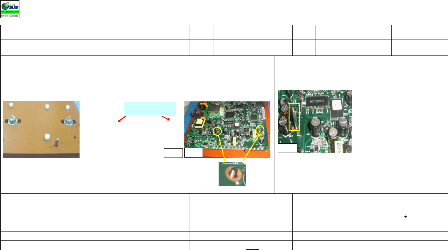
2.Take two screws and check if any damages on the them. If not, put the two screws onto the fixture with screw head down. (Photo 1)
3.Put the motherboard on the fixture. Let two screws on the fixture already go through the through holes of the motherboard. (Photo 2)
Photo 1
Put the 2 screws with screw
head down on the fixture
Photo 2
4.Take two metal stand offs and make sure there is no damage on them. If so, put the metal
stand offs onto the two screws and use hex driver to fasten them. (Photo 3)
5. Confirm 5S checklist after operate,any abnormal inform line leader.
photo 3
站別/站數 作業人數 安全防護 文件版本 發行日期 擬案 機構會簽 製造組長會簽 核准
Station NO. Person Safety Protection Doc. Rev. Issue Date Prepared Approved2 Approved2 Approved1
3/12 1
wear ESD gloves
and wrist
stra
p,
button slevees REV02 2006/9/6 Laurie Wang
數量
Q
T
1
工作指導書
WORKING INSTRUCTION
組裝段 作業名稱 : 組裝网卡&主板 主件料號:80-BETNGN-00P
機種別/版本 文件編號
MODEL NAME/REV. Doc. NO.
TM552 WRM M3-701-C06VPA023
料號
Part NO. 品名
Descriptio
n
耗材(品名/料號/規格)
Consumers 治工具(品名/料號/規格)
Fixture &Tool
s
13GB4710P560-1 plastic stand off
1.Confirm 5M checklist before assembly: 5M (manpower, machine, material, method, measurement), if any abnormal, please inform the line leader.
2. Take WRM and check whether any missing or scratch on the WRM to make sure the pins of LAN JACK, antenna connecter & reset button
are good. Also make sure that solder side is not scrathced or the WRM FW and S/N label is legible, if anything defect, just put it into defect
box.
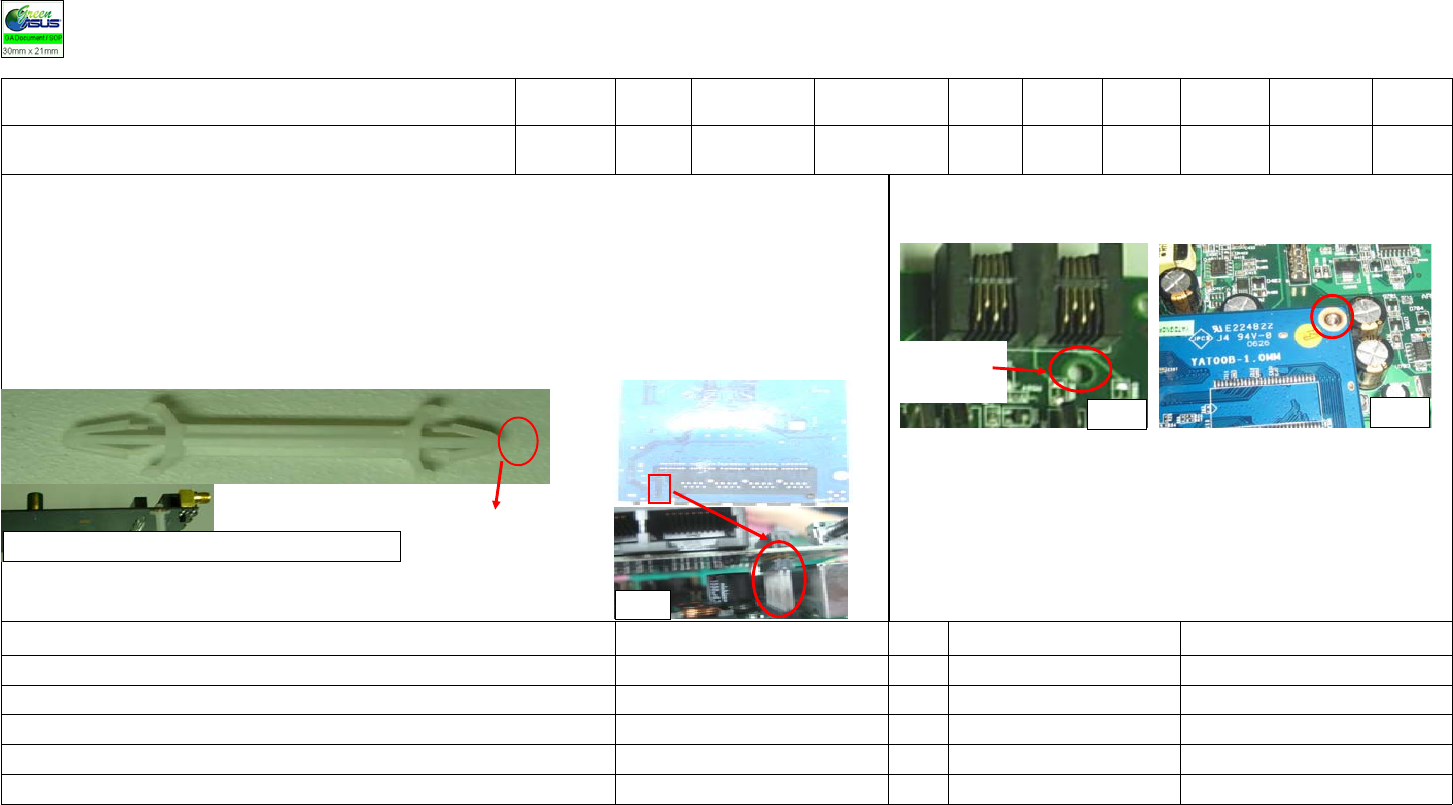
3.Take 1 plastic stand off and inspect it to make sure no bending and no scratched. And then, fasten the small foot of the plastic stand off to the
bottom side of WRM (Photo 1)
4.Get the WRM and carefully aim at the 2x 12 pin holes to the pin header (location on P601) on the mother board and then plug the pins into
the holes.
7. Check whether the plastic stand was opposite after inserting.Check method:
(1)VI the size of plastic stand's two ends
(2)Whether end is loose when plastic stand off is pluged to WRM and to mother
board, it
shows it's plugged upside down.
Plug the plastic
stand off in
Photo 4
Photo 3
Small foot
2 x 12 Pin
header (P601)
2x 12 pin holes on WRM
Photo 2
5. Click the other end of plastic stand off to the through hole near RJ-11 on the mother
board (photo 3).
6. Align the PTH of the WRM with the two metal stand offs.(Photo 4)
Photo 1
站別/站數 作業人數 安全防護 文件版本 發行日期 擬案 機構會簽 製造組長會簽 核准
Station NO. Person Safety Protection Doc. Rev. Issue Date Prepared Approved2 Approved2 Approved1
4/12 1
wear ESD gloves
and wrist
stra
p,
button slevees REV02 2006/9/6 Laurie Wang
數量
Q
T
2
1
工作指導書
WORKING INSTRUCTION
組裝段 作業名稱 : 鎖网卡&主板 主件料號:80-BETNGN-00P
機種別/版本 文件編號
MODEL NAME/REV. Doc. NO.
TM552 WRM M3-701-C06VPA023
料號
Part NO. 品名
Descriptio
n
耗材(品名/料號/規格)
Consumers 治工具(品名/料號/規格)
Fixture &Tool
s
13GMAPXD050W screw assembly fixture
04G030002100 WRM electric screw driver (torque:2.8
0.2k
g
.f*cm
,
#1 screw driver head
)
1.Confirm 5M checklist before assembly: 5M (manpower, machine, material, method, measurement), if any abnormal, please inform the line leader.
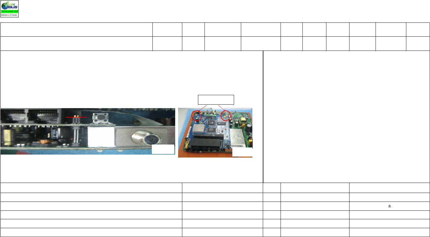
2.Take the assembled WRM and mother board from the production line,check whether the plastic stand off is clipped good, the 2x12 pins are
plugged good (all the pins need to go through the holes.) (Photo 1)
3.Get two screws and put them to the PTH of the WRM. Use electric screw driver to fasten the screws. (Photo 2)
4.Modify the torgue value of electric screw driver before operating.
5.Put the locked board on the production line.
6.Confirm 5S checklist after operate,any abnormal inform line leader.
圖二
Photo 1 Photo 2
fasten screws on

NOTICE TO USER
FCC Class B:
“NOTE: This equipment has been tested and found to comply wit
h
the limits for a Class B digital device, pursuant to Part 15 of the
FCC Rules. These limits are designed to provide reasonable
protection against harmful interference in a residential installation.
This equipment generates, uses, and can radiate radio frequency
energy and, if not installed and used in accordance with the
instructions, may cause harmful interference to radio
communications. However, there is no guarantee that interferenc
e
will not occur in a particular installation. If this equipment does
cause harmful interference to radio or television reception, which
can be determined by turning the equipment off and on, the user
is encouraged to try to correct the interference by one or more of
the following measures:
Reorient or relocate the receivin
g
antenna.
Increase the separation between the equipment and receiver
.
Connect the equipment into an outlet on a circuit
different from that to which the receiver is connected.
Consult the dealer or an experienced radio/TV technician for
help.”
Warning: Changes or modifications to this device not expressly
approved by ARRIS International, Inc. could void the user’s
authorit
y
to operate the equipment.
RF Exposure
In accordance with FCC requirements of human exposure to
radiofrequency fields, the radiating element shall be installed such
that a minimum separation distance of 20cm shall be maintained
from the user and/or
g
eneral
p
o
p
ulation
IC:
This Class Bdigital apparatus meets all requirements of the
Canadian Interference Causing Equipment Regulations. Operatio
n
is subject to the following two conditions: (1) this device may not
cause harmful interference, and (2) this device must accept any
interference received, including interference that may cause
undesired operation
.
Cet appareillage numérique de la classe Brépond à toutes les
exigences de l'interférence canadienne causant des règlements
d'équipement. L'opération est sujette aux deux conditions
suivantes: (1) ce dispositif peut ne pas causer l'interférence
nocive, et (2) ce dispositif doit accepter n'importe quelle
interférence reçue, y compris l'interférence qui peut causer
l'opération peu désirée.
NOTES:
1
This device has been designed to operate with the antennas liste
d
below, and having a maximum gain of 1.8dBi. Antennas not
included in this list or having a gain greater than 1.8dBi are strictly
prohibited for use with this device. The required antenna
im
p
edance is 50 ohms.
2
To reduce potential radio interference to other users, the antenna
type and its gain should be so chosen that the equivalent
isotropically radiated power (EIRP) is not more than that required
for successful communication. The approved antennas used with
this device are 1. C147-510023-A and 2. C66-510003-A.