ARTSYSTEM AMT-303 USN Tag User Manual AMT 303
ARTSYSTEM Co., Ltd. USN Tag AMT 303
UserManual.wiki
>
ARTSYSTEM
>
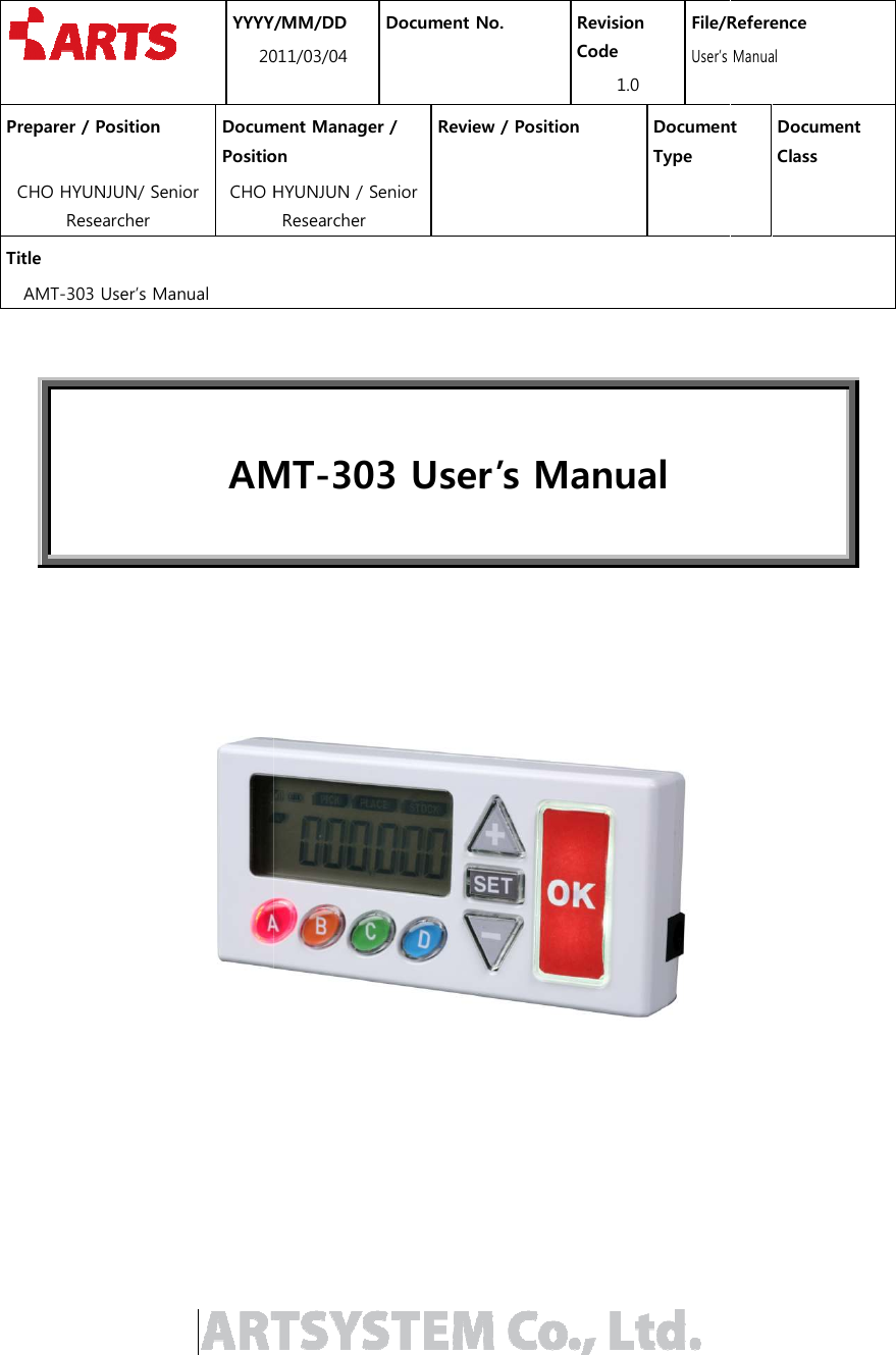
AMT 303 User Manual
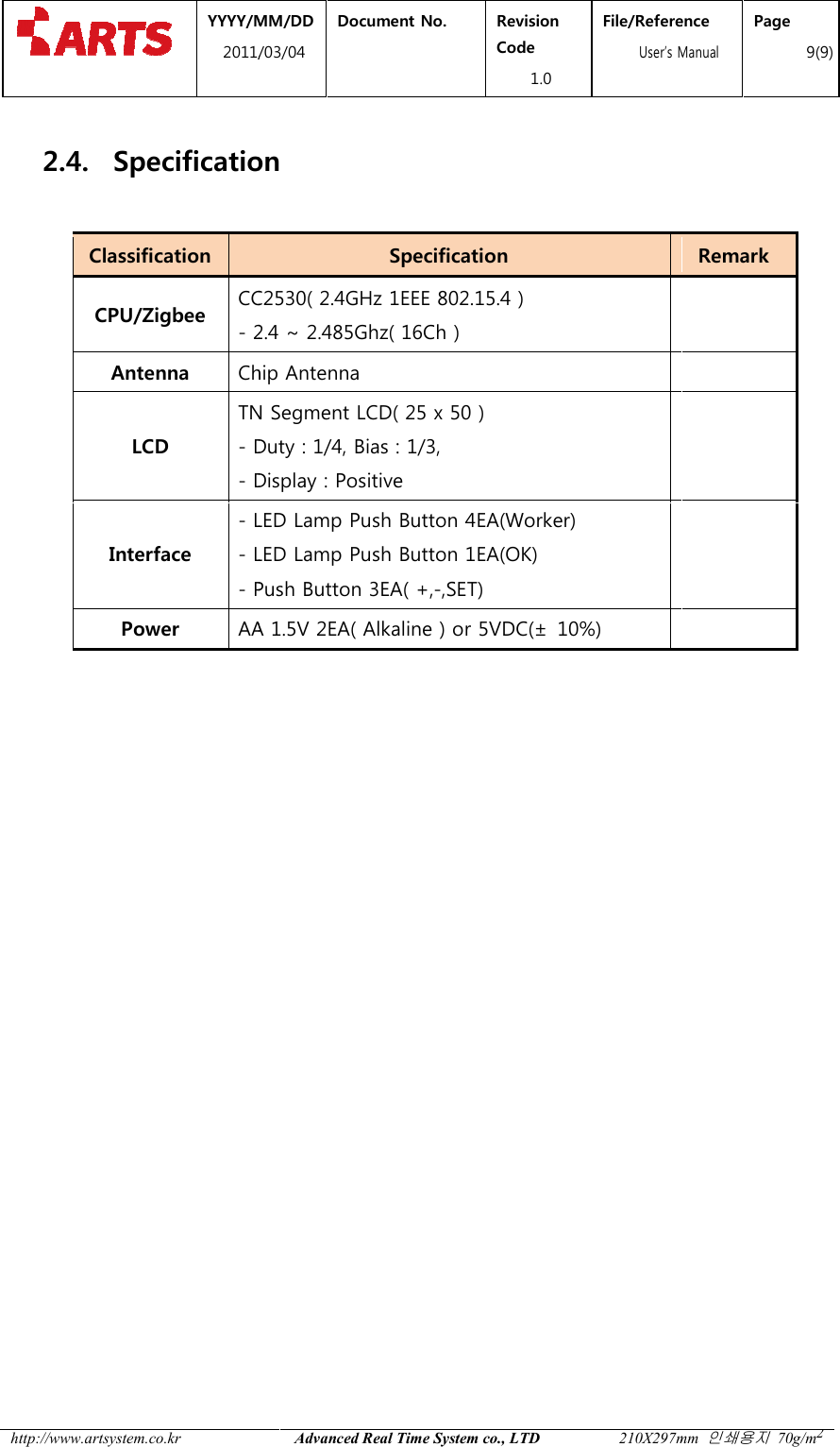
Users Manual
Navigation menu
Upload a User Manual
Namespaces
Wiki Guide
HTML
PDF
Info
Views
User Manual
Discussion / Help
Navigation