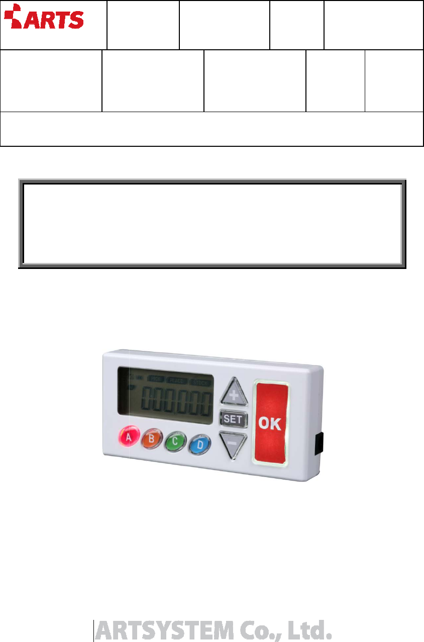
ARTSYSTEM AMT-303 USN Tag User Manual AMT 303
ARTSYSTEM Co., Ltd. USN Tag AMT 303
Users Manual
YYYY
20
Preparer / Position
Document Manager
Position
CHO HYUNJUN/ Senior
Researcher
CHO HYUNJUN
Title
AMT-303 User’s Manual
AMT
YYYY
/MM/DD
20
11/03/04
Document No.
Revision
Code
1.0
File/Reference
User’
s Manual
Document Manager
/
Position
Review / Position
Document
Type
CHO HYUNJUN
/ Senior
Researcher
AMT
-303 User’s Manual
File/Reference
s Manual
Document
Document
Class

YYYY/
MM
201
1/03
http://www.artsystem.co.kr
Document Information
Version
1.0
Preparation
Senior Researcher
Document
Name
AMT-303
User
Date
2011/03/04
State
In Working
Date
Ver.
2011.03.04 1.0
MM
/DD
1/03
/04
Document No.
Revision
Code
1.0
File/Reference
User’
s Manual
Advanced Real Time System co., LTD
210X297mm
Document Information
Senior Researcher
CHO HYUNJUN
User
’s Manual
History of Revision
Details
Revised by
Initial Preparation
CHO HYUNJUN
File/Reference
s Manual
Page
2(9)
210X297mm
인쇄용지
70g/m
2
Position
Senior
Researcher

YYYY/
MM
201
1/03
http://www.artsystem.co.kr
Table of Contents
1. OVERVIEW
................................
1.1. PURPOSE
................................
1.2. SCOPE
................................
1.3. CAUTIONS
................................
2. BASIC STRUCTURE
................................
2.1.
NAME AND FUNCTION OF
2.2.
DETAILED FUNCTION OF
2.3.
CONSIDERATIONS IN IN
2.4. SPECIFICATION
................................
MM
/DD
1/03
/04
Document No.
Revision
Code
1.0
File/Reference
User’
s Manual
Advanced Real Time System co., LTD
210X297mm
................................
................................................................
................................
................................
................................................................
................................
................................
................................................................
................................
................................
................................................................
................................
................................
................................................................
................................
NAME AND FUNCTION OF
EACH PART OF AMT-303
................................
DETAILED FUNCTION OF
EACH PART OF AMT-303
................................
CONSIDERATIONS IN IN
STALLATION ................................
................................
................................
................................................................
................................
File/Reference
s Manual
Page
3(9)
210X297mm
인쇄용지
70g/m
2
................................
............................ 4
................................
.......................... 4
................................
................................ 4
................................
....................... 4
................................
............ 6
................................
........................... 6
................................
................................ 7
................................
.............................. 8
................................
............. 9

YYYY/
MM
201
1/03
http://www.artsystem.co.kr
1. Overview
This document is prepared for the right use of AMT
equipment at the best condition with right handling methods
understand this manual before using the
The specification is subject to change without notice, if necessary for improvement of
performance
If you have any
inquiries
For safety, carefully read safety items in this manual before use.
1.1. Purpose
This document is the user
1.2. Scope
This document covers the structure and the operation methods of AMT
1.3. Cautions
Cautions for
Installation and Operation
-
Beware of electric shock in installing and operating the equipment as it uses DC 5
power.
Do not pull out the power supply and touch it with wet hands. You may
have electric shock.
- Check whether
the output of the
the equipment
before using
-
We are not responsible for problems caused by using
-
Avoid a place with direct sun rays and a closed hot and humid place when selecting
an installation and
storage position. Install and store the equipment
place
under room temperature.
can reduce the life span of the product.
Cautions for Maintenance
-
Do not place a strong impact on the equipment and do not drill the equipment.
Otherwise, the equipment may be broken or the life span of the product can be
short.
MM
/DD
1/03
/04
Document No.
Revision
Code
1.0
File/Reference
User’
s Manual
Advanced Real Time System co., LTD
210X297mm
This document is prepared for the right use of AMT
-
303, P2L TAG. To maintain the
equipment at the best condition with right handling methods
, carefully read and fully
understand this manual before using the
equipment.
The specification is subject to change without notice, if necessary for improvement of
inquiries
, please do not hesitate to contact us, the Art System
For safety, carefully read safety items in this manual before use.
This document is the user
’s manual of AMT-303
This document covers the structure and the operation methods of AMT
Installation and Operation
Beware of electric shock in installing and operating the equipment as it uses DC 5
Do not pull out the power supply and touch it with wet hands. You may
have electric shock.
the output of the
adaptor is DC 5V
and remove the
before using
it.
We are not responsible for problems caused by using
a
power other than DC 5V
Avoid a place with direct sun rays and a closed hot and humid place when selecting
storage position. Install and store the equipment
under room temperature.
Installing and storing it in a hot and humid place
can reduce the life span of the product.
Cautions for Maintenance
Do not place a strong impact on the equipment and do not drill the equipment.
Otherwise, the equipment may be broken or the life span of the product can be
File/Reference
s Manual
Page
4(9)
210X297mm
인쇄용지
70g/m
2
303, P2L TAG. To maintain the
, carefully read and fully
The specification is subject to change without notice, if necessary for improvement of
, please do not hesitate to contact us, the Art System
Co., Ltd.
This document covers the structure and the operation methods of AMT
-303
Beware of electric shock in installing and operating the equipment as it uses DC 5
V
Do not pull out the power supply and touch it with wet hands. You may
and remove the
battery from
power other than DC 5V
Avoid a place with direct sun rays and a closed hot and humid place when selecting
storage position. Install and store the equipment
in an indoor
Installing and storing it in a hot and humid place
Do not place a strong impact on the equipment and do not drill the equipment.
Otherwise, the equipment may be broken or the life span of the product can be

YYYY/
MM
201
1/03
http://www.artsystem.co.kr
Cautions for Disassembly
-
Do not disassemble, repair and modify the equipment, except an au
We are not
responsible
Cautions According to Surrounding Environment
-
This product adopts wireless communication using ZigBee. Therefore,
communication status can be worse because of surrounding environment.
SPECIFY SERVICE INSTRUCTIONS AND WARRANTY TERMS
This device complies with part 15 of the FCC Rules. Oper
(1) this device may not cause harmful interference; and (2) this device must accept any interference
received, including interference that may cause undesired operation.
This equipment has
been tested and found to comply with the limits for a Class B digital device, pursuant to
Part 15 of FCC Rules. These limits are designed to provide reasonable protection against harmful
interference in a residential installation. This equipme
energy. If not installed and used in accordance with the instructions, it may cause harmful interference to
radio communications. However, there is no guarantee that interference will not occu
installation. If this equipment does cause harmful interference to radio or television reception, which can be
determined by turning the equipment off and on, the user is encouraged to try and correct the interference
by
one or more of the following measures:
-
Reorient or relocate the receiving antenna.
-
Increase the distance between the equipment and the receiver.
-
Connect the equipment to outlet on a circuit different from that to which the receiver
-
Consult the dealer or an experienced radio/TV technician for help.
Any changes or modifications not expressly approved by the party responsible for compliance could void the
user’s authority to operate the equipment.
FCC NOTE:
THE MANUFACTURER IS NOT RESPONSIBLE FOR ANY RADIO OR TV INTERFERENCE
CAUSED BY UNAUTHORIZED MODIFICATIONS TO THIS EQUIPMENT.
SUCH MODIFICATIONS COULD VOID THE USER'S AUTHORITY TO OPERATE THE
EQUIPMENT
MM
/DD
1/03
/04
Document No.
Revision
Code
1.0
File/Reference
User’
s Manual
Advanced Real Time System co., LTD
210X297mm
Cautions for Disassembly
Do not disassemble, repair and modify the equipment, except an au
responsible
for any problems caused by disassembly without permission
Cautions According to Surrounding Environment
This product adopts wireless communication using ZigBee. Therefore,
communication status can be worse because of surrounding environment.
SPECIFY SERVICE INSTRUCTIONS AND WARRANTY TERMS
This device complies with part 15 of the FCC Rules. Oper
ation is subject to the following two conditions:
(1) this device may not cause harmful interference; and (2) this device must accept any interference
received, including interference that may cause undesired operation.
been tested and found to comply with the limits for a Class B digital device, pursuant to
Part 15 of FCC Rules. These limits are designed to provide reasonable protection against harmful
interference in a residential installation. This equipme
nt generates, uses, and can radiate radio frequency
energy. If not installed and used in accordance with the instructions, it may cause harmful interference to
radio communications. However, there is no guarantee that interference will not occu
r in a particular
installation. If this equipment does cause harmful interference to radio or television reception, which can be
determined by turning the equipment off and on, the user is encouraged to try and correct the interference
one or more of the following measures:
Reorient or relocate the receiving antenna.
Increase the distance between the equipment and the receiver.
Connect the equipment to outlet on a circuit different from that to which the receiver
Consult the dealer or an experienced radio/TV technician for help.
Any changes or modifications not expressly approved by the party responsible for compliance could void the
user’s authority to operate the equipment.
THE MANUFACTURER IS NOT RESPONSIBLE FOR ANY RADIO OR TV INTERFERENCE
CAUSED BY UNAUTHORIZED MODIFICATIONS TO THIS EQUIPMENT.
SUCH MODIFICATIONS COULD VOID THE USER'S AUTHORITY TO OPERATE THE
File/Reference
s Manual
Page
5(9)
210X297mm
인쇄용지
70g/m
2
Do not disassemble, repair and modify the equipment, except an au
thorized person.
for any problems caused by disassembly without permission
This product adopts wireless communication using ZigBee. Therefore,
communication status can be worse because of surrounding environment.
ation is subject to the following two conditions:
(1) this device may not cause harmful interference; and (2) this device must accept any interference
been tested and found to comply with the limits for a Class B digital device, pursuant to
Part 15 of FCC Rules. These limits are designed to provide reasonable protection against harmful
nt generates, uses, and can radiate radio frequency
energy. If not installed and used in accordance with the instructions, it may cause harmful interference to
r in a particular
installation. If this equipment does cause harmful interference to radio or television reception, which can be
determined by turning the equipment off and on, the user is encouraged to try and correct the interference
is connected.
Any changes or modifications not expressly approved by the party responsible for compliance could void the
THE MANUFACTURER IS NOT RESPONSIBLE FOR ANY RADIO OR TV INTERFERENCE
SUCH MODIFICATIONS COULD VOID THE USER'S AUTHORITY TO OPERATE THE
YYYY/
MM
201
1/03
http://www.artsystem.co.kr
2.
Basic Structure
2.1.
Name and Function of Each Part of
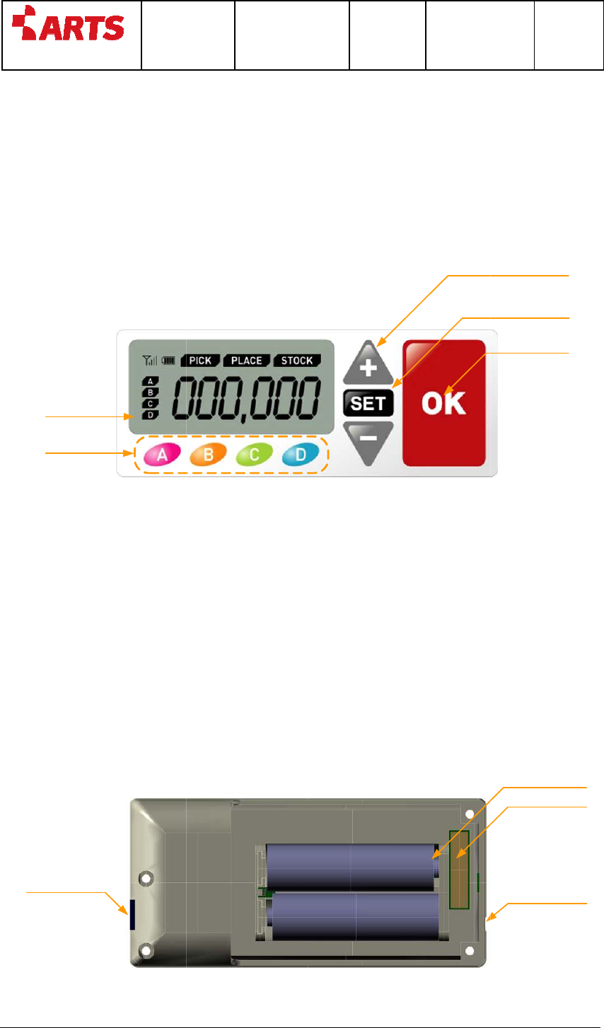
2.1.1. The Front
LCD Display
LED Button
The front of the product consists of the following items as shown in the picture
above.
- LCD
- 4 LED Buttons f
or Work
-
2 Quantity Modification Button
- 1 SET Button
- 1 OK LED
Button
2.1.2. The Back
DC 5V Adapter
Socket
MM
/DD
1/03
/04
Document No.
Revision
Code
1.0
File/Reference
User’
s Manual
Advanced Real Time System co., LTD
210X297mm
Basic Structure
Name and Function of Each Part of
AMT-3
0
Quantity Modification Buttons
OK LED Button
The front of the product consists of the following items as shown in the picture
or Work
Identification
2 Quantity Modification Button
s
Button
Battery Inserting Part
File/Reference
s Manual
Page
6(9)
210X297mm
인쇄용지
70g/m
2
0
3
Quantity Modification Buttons
SET Button
OK LED Button
The front of the product consists of the following items as shown in the picture
Battery Inserting Part
(AA type)
7 Pins Socket
Reset Button

YYYY/
MM
201
1/03
http://www.artsystem.co.kr
The back of the product consists of the following items as shown in the picture
above.
-
Battery Inserting Part
- DC 5V
Adapter Socket
- RESET Button
- 7 Pins Socket
1 Port ( F/W Upgrade )
2.2. Detailed
Function
2.2.1. LCD Display
LCD displays RF
reception sensitivity
quantity and workers
2.2.2. LED Button
LED buttons are located to
work order, a corresponding LED button is blinking to show that the work is in
progress.
2.2.3.
Quantity Modification Button
Quantity Modification Button
changed..
2.2.4. OK
Button
It is used for work completion order and confirmation.
2.2.5.
Power Supply Part
DC5V
- DC5V
power connector supplies DC 5V power which is converted via an external
adaptor.
Battery Inserting Part
-
Insert two AA batteries (1.5V) to supply power, paying attention to the direction
MM
/DD
1/03
/04
Document No.
Revision
Code
1.0
File/Reference
User’
s Manual
Advanced Real Time System co., LTD
210X297mm
The back of the product consists of the following items as shown in the picture
Battery Inserting Part
Adapter Socket
1 Port ( F/W Upgrade )
Function
of Each Part of AMT-303
reception sensitivity
, battery condition, work data, working
quantity and workers
LED buttons are located to
distinguish
four different works. When they receive a
work order, a corresponding LED button is blinking to show that the work is in
Quantity Modification Button
Quantity Modification Button
s change quantity when work descriptions have been
It is used for work completion order and confirmation.
Power Supply Part
power connector supplies DC 5V power which is converted via an external
Battery Inserting Part
Insert two AA batteries (1.5V) to supply power, paying attention to the direction
File/Reference
s Manual
Page
7(9)
210X297mm
인쇄용지
70g/m
2
The back of the product consists of the following items as shown in the picture
, battery condition, work data, working
four different works. When they receive a
work order, a corresponding LED button is blinking to show that the work is in
s change quantity when work descriptions have been
power connector supplies DC 5V power which is converted via an external
Insert two AA batteries (1.5V) to supply power, paying attention to the direction

YYYY/
MM
201
1/03
http://www.artsystem.co.kr
However, in the battery mode, the external adapter should be removed.
RESET
-
Reset button conducts initialization of the
2.2.6. External
Interface
7 pin Connector
-
It is used to update the product.
2.3.
Considerations in Installation
Install the product in the center of the
network management and communication. The interior and allocation of the pro
can affect the communication.
Place the product in open space. Check whether there are metals, which may
interfere with the communication
communication may be not smoothly established.
If you have any
inquires
manufacturer
MM
/DD
1/03
/04
Document No.
Revision
Code
1.0
File/Reference
User’
s Manual
Advanced Real Time System co., LTD
210X297mm
However, in the battery mode, the external adapter should be removed.
Reset button conducts initialization of the
product
Interface
It is used to update the product.
A user should not use this connector.
Considerations in Installation
Install the product in the center of the
ZigBee
Network for optimized
network management and communication. The interior and allocation of the pro
can affect the communication.
Place the product in open space. Check whether there are metals, which may
interfere with the communication
. If there are many metals near the product, the
communication may be not smoothly established.
inquires
while using and operating the system, please contact the
File/Reference
s Manual
Page
8(9)
210X297mm
인쇄용지
70g/m
2
However, in the battery mode, the external adapter should be removed.
A user should not use this connector.
Network for optimized
ZigBee
network management and communication. The interior and allocation of the pro
ducts
Place the product in open space. Check whether there are metals, which may
. If there are many metals near the product, the
while using and operating the system, please contact the

YYYY/
MM
201
1/03
http://www.artsystem.co.kr
2.4.
Specification
Classification
CPU/Zigbee
CC2530( 2.4GHz 1EEE 802.15.4 )
-
2.4 ~ 2.485Ghz( 16Ch )
Antenna
Chip Antenna
LCD
TN Segment LCD( 25 x
-
Duty : 1/4, Bias : 1/3,
-
Display : Positive
Interface
-
LED Lamp Push Button 4EA(Worker)
-
LED Lamp Push Button 1EA(OK)
-
Push Button 3EA( +,
Power
AA 1.5V 2EA( Alkaline ) or 5VDC(
MM
/DD
1/03
/04
Document No.
Revision
Code
1.0
File/Reference
User’
s Manual
Advanced Real Time System co., LTD
210X297mm
Specification
Specification
CC2530( 2.4GHz 1EEE 802.15.4 )
2.4 ~ 2.485Ghz( 16Ch )
Chip Antenna
TN Segment LCD( 25 x
50 )
Duty : 1/4, Bias : 1/3,
Display : Positive
LED Lamp Push Button 4EA(Worker)
LED Lamp Push Button 1EA(OK)
Push Button 3EA( +,
-,SET)
AA 1.5V 2EA( Alkaline ) or 5VDC(
± 10%)
File/Reference
s Manual
Page
9(9)
210X297mm
인쇄용지
70g/m
2
Remark