ASSALOY Global Solutions Norway AS 4827610CC1 RFID and BLE reader LCU 5350 User Manual Enter the help project title here
ASSA ABLOY Hospitality AS RFID and BLE reader LCU 5350 Enter the help project title here
UserManual.wiki
>
ASSALOY Global Solutions Norway AS
>
4827610CC1 User Manual
user manual
Navigation menu
Upload a User Manual
Namespaces
Wiki Guide
HTML
PDF
Info
Views
User Manual
Discussion / Help
Navigation
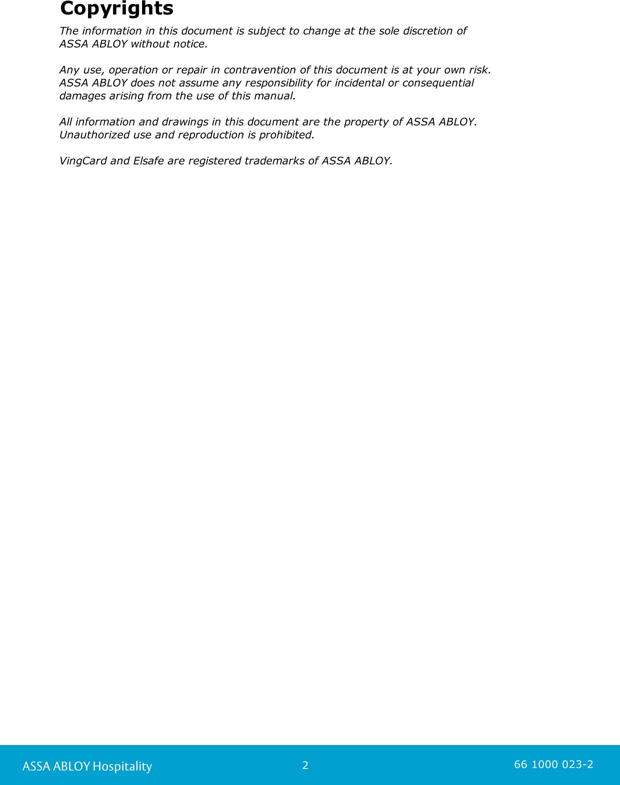
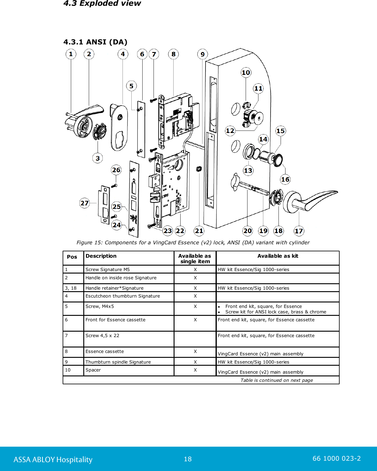
![19ASSA ABLOY Hospitality 66 1000 023-2PosDescriptionAvailable as single itemAvailable as kit11LCU 5350XVingCard Essence (v2) main assembly12Service coverXVingCard Essence (v2) main assembly13Cylinder rose XCylinder ring kit Signature14Spring cylinder rose Signature XCylinder ring kit Signature15Cyl 5-lev Std thread front prof RXCyl 5-lev A ADB thread front prof RXCyl 5-lev E ADB thread front prof RX16Cylinder sealing assy XCylinder ring kit Signature [finish] XXmm w/seal17Handle on outside rose SignatureX18See 3, 18XHW kit Essence/Sig 1000-series19Spindle handle male Signature XSquare spindle assy Signature *)20Spindle handle female Signature XSquare spindle assy Signature *)21 Spindle locking clipXHW kit Essence/Sig 1000-series22Lock case ANSI DAXLock case ANSI DA ADBX23Screw wood, countersunk 5X25 mmXScrew kit for ANSI lock case, brass & chrome24Screw, M4x5XFront end kit, square, for Essence cassetteScrew kit for ANSI lock case, brass & chrome25Lock front ANSIXLock front ANSI ADBX26Screw 5,00x12 st 4,8 Zinc colorScrew kit for ANSI lock case, brass & chromeScrew 5,00x12 st 4,8 Yellow colorScrew kit for ANSI lock case, brass & chromeScrew, wood, countersunk, 5x25mm,Metal zinc colorScrew kit for ANSI lock case, brass & chromeScrew, wood, countersunk, 5x25mm,Metal yellow colorScrew kit for ANSI lock case, brass & chrome27Striker plate ANSIXStriker plate ANSI ADBX Table 5 *) 'Square spindle assy Signature’ is sold as a separate kit, but is also included in 'HW kit Essence/Sig 1000-series'.](https://usermanual.wiki/ASSALOY-Global-Solutions-Norway-AS/4827610CC1/User-Guide-3283941-Page-19.png)
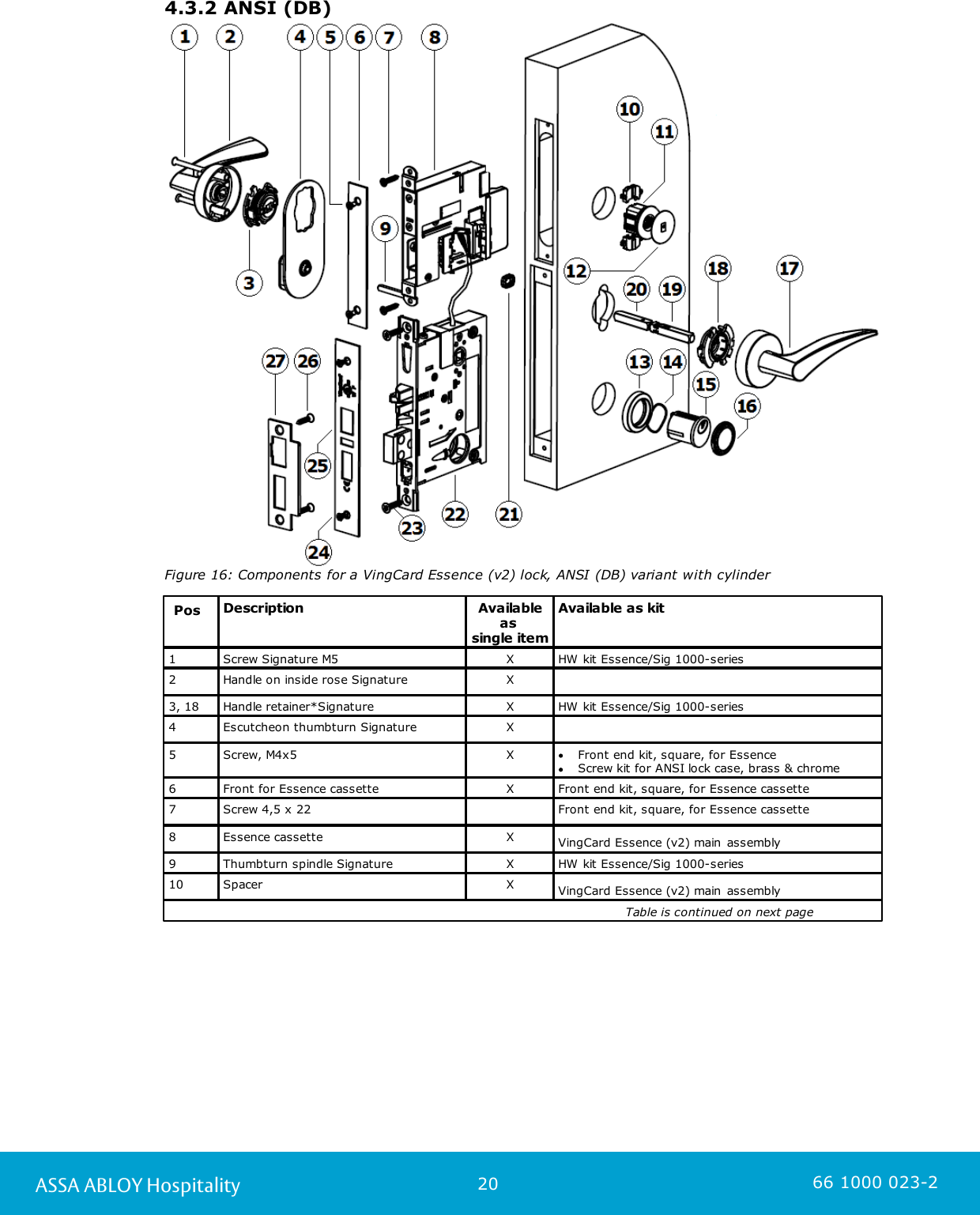
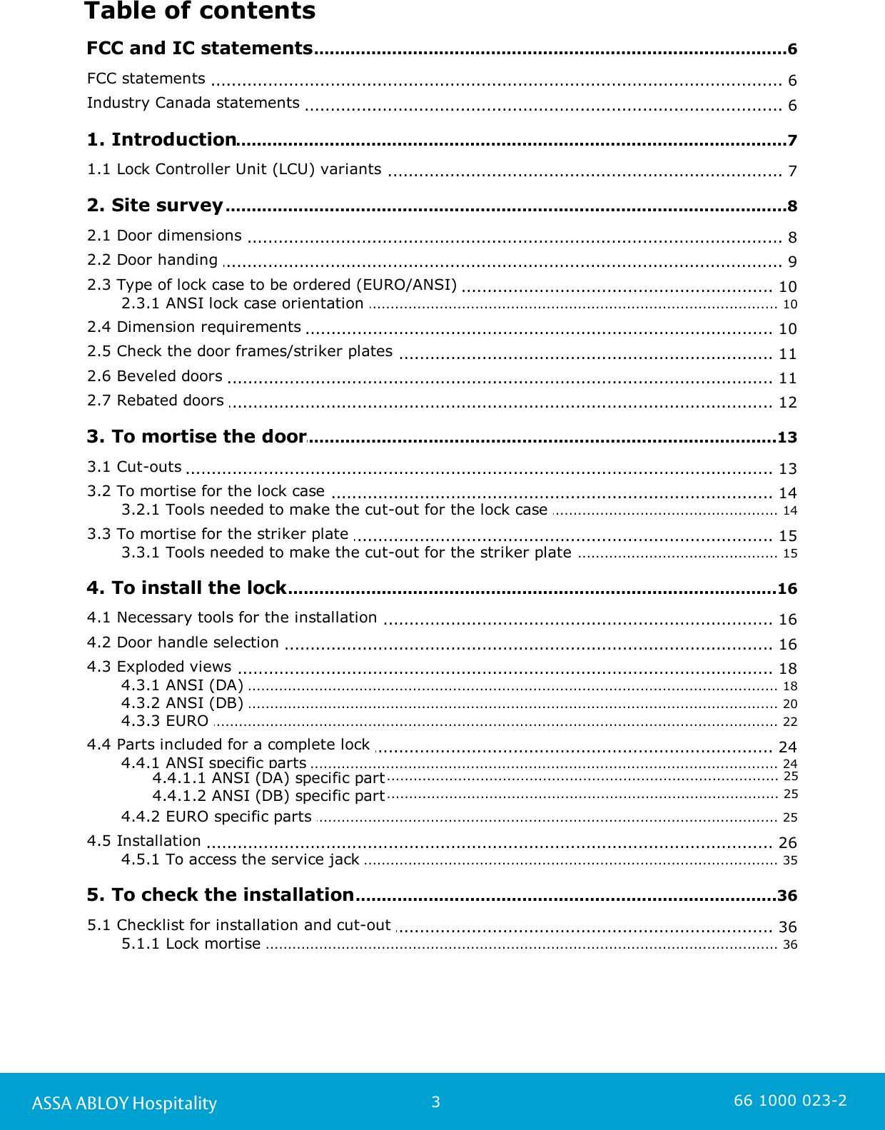
![21ASSA ABLOY Hospitality 66 1000 023-2PosDescriptionAvailableas single itemAvailable as kit11LCU 5350XVingCard Essence (v2) main assembly12Service coverXVingCard Essence (v2) main assembly13Cylinder rose XCylinder ring kit Signature14Spring cylinder rose Signature XCylinder ring kit Signature15Cyl 5-lev Std thread front prof RXCyl 5-lev A ADB thread front prof RXCyl 5-lev E ADB thread front prof RX16Cylinder sealing assy XCylinder ring kit Signature [finish] XXmm w/seal17Handle on outside rose SignatureX18See 3, 18XHW kit Essence/Sig 1000-series19Spindle handle male Signature XSquare spindle assy Signature *)20Spindle handle female Signature XSquare spindle assy Signature *)21 Spindle locking clipXHW kit Essence/Sig 1000-series22Lock case ANSI DBXLock case ANSI DB ADBX23Screw wood, countersunk 5X25 mmXScrew kit for ANSI lock case, brass & chrome24Screw, M4x5XFront end kit, square, for Essence cassetteScrew kit for ANSI lock case, brass & chrome25Lock front ANSIXLock front ANSI ADBX26Screw 5,00x12 st 4,8 Zinc colorScrew kit for ANSI lock case, brass & chromeScrew 5,00x12 st 4,8 Yellow colorScrew kit for ANSI lock case, brass & chromeScrew, wood, countersunk, 5x25mm,Metal zinc colorScrew kit for ANSI lock case, brass & chromeScrew, wood, countersunk, 5x25mm,Metal yellow colorScrew kit for ANSI lock case, brass & chrome27Striker plate ANSIXStriker plate ANSI ADBX Table 6*) 'Square spindle assy Signature’ is sold as a separate kit, but is also included in 'HW kit Essence/Sig 1000-series'.](https://usermanual.wiki/ASSALOY-Global-Solutions-Norway-AS/4827610CC1/User-Guide-3283941-Page-21.png)
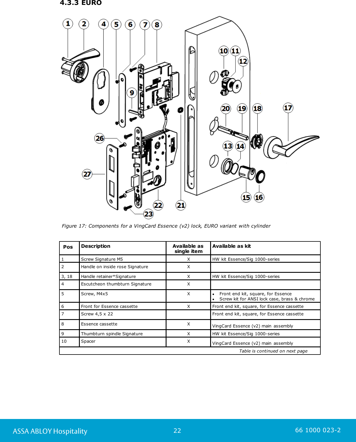
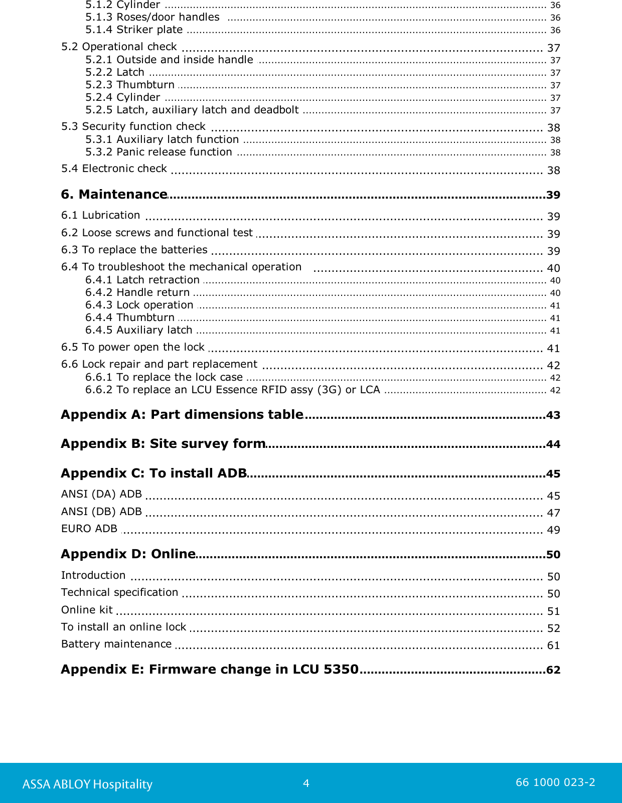
![23ASSA ABLOY Hospitality 66 1000 023-2PosDescriptionAvailable as single itemAvailable as kit11LCU 5350XVingCard Essence (v2) main assembly12Service coverXVingCard Essence (v2) main assembly13Cylinder rose XCylinder ring kit Signature14Spring cylinder rose Signature XCylinder ring kit Signature15Cyl 5-lev Std thread front prof RXCyl 5-lev A ADB thread front prof RXCyl 5-lev E ADB thread front prof RX16Cylinder sealing assy XCylinder ring kit Signature [finish] XXmm w/seal17Handle on outside rose SignatureX18See 3, 18XHW kit Essence/Sig 1000-series19Spindle handle male Signature XSquare spindle assy Signature *)20Spindle handle female Signature XSquare spindle assy Signature *)21 Spindle locking clipXHW kit Essence/Sig 1000-series22Lock case EUROXLock case EURO ADBX23Screw wood, countersunk 5X25 mmXScrew kit for ANSI lock case, brass & chrome24Not applicable for EURO25Not applicable for EURO26Screw 5,00x12 st 4,8 Zinc colorScrew kit for ANSI lock case, brass & chromeScrew 5,00x12 st 4,8 Yellow colorScrew kit for ANSI lock case, brass & chromeScrew, wood, countersunk, 5x25mm, Metal zinc colorScrew kit for ANSI lock case, brass & chromeScrew, wood, countersunk, 5x25mm, Metal yellow colorScrew kit for ANSI lock case, brass & chrome27Striker plate EUROX Table 7 *) 'Square spindle assy Signature’ is sold as a separate kit, but is also included in 'HW kit Essence/Sig 1000-series'.](https://usermanual.wiki/ASSALOY-Global-Solutions-Norway-AS/4827610CC1/User-Guide-3283941-Page-23.png)