ASSALOY Global Solutions Norway AS 4827610CC1 RFID and BLE reader LCU 5350 User Manual Enter the help project title here
ASSA ABLOY Hospitality AS RFID and BLE reader LCU 5350 Enter the help project title here
user manual

1
ASSA ABLOY Hospitality 66 1000 023-2
User Manual
VingCard Essence (v2)

2
ASSA ABLOY Hospitality 66 1000 023-2
Copyrights
The information in this document is subject to change at the sole discretion of
ASSA ABLOY without notice.
Any use, operation or repair in contravention of this document is at your own risk.
ASSA ABLOY does not assume any responsibility for incidental or consequential
damages arising from the use of this manual.
All information and drawings in this document are the property of ASSA ABLOY.
Unauthorized use and reproduction is prohibited.
VingCard and Elsafe are registered trademarks of ASSA ABLOY.

3
ASSA ABLOY Hospitality 66 1000 023-2
Table of contents
.............................................................................................................................6 FCC and IC statements
.............................................................................................................................. 6
FCC statements
.............................................................................................................................. 6
Industry Canada statements
.............................................................................................................................7 1. Introduction
.............................................................................................................................. 7
1.1 Lock Controller Unit (LCU) variants
.............................................................................................................................8 2. Site survey
.............................................................................................................................. 8
2.1 Door dimensions
.............................................................................................................................. 9
2.2 Door handing
.............................................................................................................................. 10
2.3 Type of lock case to be ordered (EURO/ANSI)
................................................................................................................................................ 102.3.1 ANSI lock case orientation
.............................................................................................................................. 10
2.4 Dimension requirements
.............................................................................................................................. 11
2.5 Check the door frames/striker plates
.............................................................................................................................. 11
2.6 Beveled doors
.............................................................................................................................. 12
2.7 Rebated doors
.............................................................................................................................13 3. To mortise the door
.............................................................................................................................. 13
3.1 Cut-outs
.............................................................................................................................. 14
3.2 To mortise for the lock case
................................................................................................................................................ 143.2.1 Tools needed to make the cut-out for the lock case
.............................................................................................................................. 15
3.3 To mortise for the striker plate
................................................................................................................................................ 153.3.1 Tools needed to make the cut-out for the striker plate
.............................................................................................................................16 4. To install the lock
.............................................................................................................................. 16
4.1 Necessary tools for the installation
.............................................................................................................................. 16
4.2 Door handle selection
.............................................................................................................................. 18
4.3 Exploded views
................................................................................................................................................ 184.3.1 ANSI (DA)
................................................................................................................................................ 204.3.2 ANSI (DB)
................................................................................................................................................ 224.3.3 EURO
.............................................................................................................................. 24
4.4 Parts included for a complete lock
................................................................................................................................................ 244.4.1 ANSI specific parts
....................................................................................................................................... 25
4.4.1.1 ANSI (DA) specific part
....................................................................................................................................... 25
4.4.1.2 ANSI (DB) specific part
................................................................................................................................................ 254.4.2 EURO specific parts
.............................................................................................................................. 26
4.5 Installation
................................................................................................................................................ 354.5.1 To access the service jack
.............................................................................................................................36 5. To check the installation
.............................................................................................................................. 36
5.1 Checklist for installation and cut-out
................................................................................................................................................ 365.1.1 Lock mortise

4
ASSA ABLOY Hospitality 66 1000 023-2
................................................................................................................................................ 365.1.2 Cylinder
................................................................................................................................................ 365.1.3 Roses/door handles
................................................................................................................................................ 365.1.4 Striker plate
.............................................................................................................................. 37
5.2 Operational check
................................................................................................................................................ 375.2.1 Outside and inside handle
................................................................................................................................................ 375.2.2 Latch
................................................................................................................................................ 375.2.3 Thumbturn
................................................................................................................................................ 375.2.4 Cylinder
................................................................................................................................................ 375.2.5 Latch, auxiliary latch and deadbolt
.............................................................................................................................. 38
5.3 Security function check
................................................................................................................................................ 385.3.1 Auxiliary latch function
................................................................................................................................................ 385.3.2 Panic release function
.............................................................................................................................. 38
5.4 Electronic check
.............................................................................................................................39 6. Maintenance
.............................................................................................................................. 39
6.1 Lubrication
.............................................................................................................................. 39
6.2 Loose screws and functional test
.............................................................................................................................. 39
6.3 To replace the batteries
.............................................................................................................................. 40
6.4 To troubleshoot the mechanical operation
................................................................................................................................................ 406.4.1 Latch retraction
................................................................................................................................................ 406.4.2 Handle return
................................................................................................................................................ 416.4.3 Lock operation
................................................................................................................................................ 416.4.4 Thumbturn
................................................................................................................................................ 416.4.5 Auxiliary latch
.............................................................................................................................. 41
6.5 To power open the lock
.............................................................................................................................. 42
6.6 Lock repair and part replacement
................................................................................................................................................ 426.6.1 To replace the lock case
................................................................................................................................................ 426.6.2 To replace an LCU Essence RFID assy (3G) or LCA
.............................................................................................................................43 Appendix A: Part dimensions table
.............................................................................................................................44 Appendix B: Site survey form
.............................................................................................................................45 Appendix C: To install ADB
.............................................................................................................................. 45
ANSI (DA) ADB
.............................................................................................................................. 47
ANSI (DB) ADB
.............................................................................................................................. 49
EURO ADB
.............................................................................................................................50 Appendix D: Online
.............................................................................................................................. 50
Introduction
.............................................................................................................................. 50
Technical specification
.............................................................................................................................. 51
Online kit
.............................................................................................................................. 52
To install an online lock
.............................................................................................................................. 61
Battery maintenance
.............................................................................................................................62 Appendix E: Firmware change in LCU 5350

5
ASSA ABLOY Hospitality 66 1000 023-2
.............................................................................................................................63 Appendix F: Summary of notes
.............................................................................................................................66 Revision history

6
ASSA ABLOY Hospitality 66 1000 023-2
FCC and IC statements
FCC (Federal Communications Commission) statements
This device complies with Part 15 of the FCC Rules. Operation is subject to the
following two conditions:
(1) this device may not cause harmful interference, and
(2) this device must accept any interference received, including interference
that may cause undesired operation.
Note: This equipment has been tested and found to comply with the limits for a
Class A digital device, pursuant to part 15 of the FCC Rules. These limits are designed
to provide reasonable protection against harmful interference when the equipment
is operated in a commercial environment. This equipment generates, uses and can
radiate radio frequency energy and, if not installed and used in accordance with
the instruction manual, may cause harmful interference to radio communications.
Operation of this equipment in a residential area is likely to cause harmful
interference; in which case, correction of the interference is at the user's expense.
Important: Changes or modifications to an intentional or unintentional
radiator not expressly approved by the party responsible for compliance
could void the user's authority to operate the equipment.
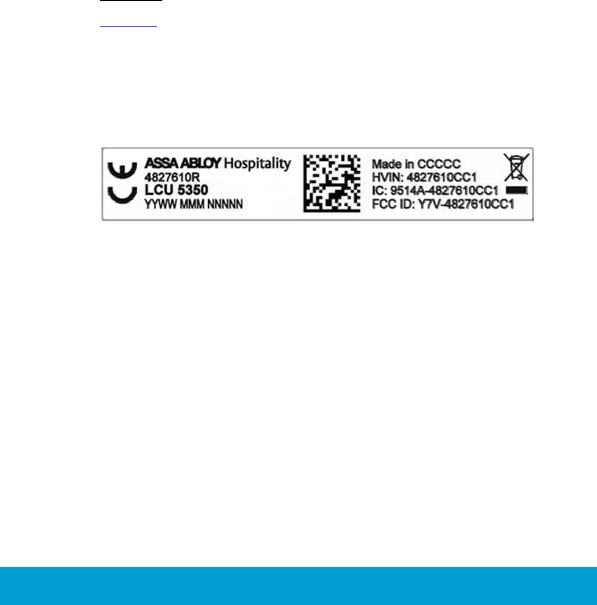
The LCU (lock controller unit) must be labeled to say 'FCC ID: Y7V-4827610CC1'.
IC (Industry Canada) statements
This device complies with Industry Canada licence-exempt RSS standard(s).
Operation is subject to the following two conditions:
(1) this device may not cause interference, and
(2) this device must accept any interference, including interference
that may cause undesired operation of the device.
Le présent appareil est conforme aux CNR d’Industrie Canada applicables aux
appareils radio exempts de licence. L’exploitation est autorisée aux deux
conditions suivantes:
(1) l'appareil ne doit pas produire de brouillage, et
(2) l’utilisateur de l'appareil doit accepter tout brouillage radioélectrique subi,
même si le brouillage est susceptible d’en compromettre le fonctionnement.
The LCU (lock controller unit) is labeled 'IC:9514A-4827610CC1'.
The term "IC" before the equipment certification number only signifies that
the Industry Canada technical specifications were met.
Le terme "IC" devant le numéro de certification signifie seulement que les
specifications techniques Industrie Canada ont été respectées.
7
ASSA ABLOY Hospitality 66 1000 023-2
1. Introduction
The purpose of this document is to give the distributors of VingCard Essence (v2)
locks sufficient information to install and support this type of lock. This manual
contains descriptions and drawings needed for installation, maintenance and
troubleshooting of VingCard Essence (v2). Site survey before installation is also
covered in this document. The VingCard Essence (v2) lock can be used together
with the Visionline system. All dimensions in this manual (where applicable) are
given in mm and inches.
Important: VingCard Essence (v2) can only be installed in non-metallic doors.
Appendix F in this manual contains a summary of the tips, important notes and
cautions from the different sections of this manual. It can be used as an overview
and a reference for different phases of VingCard Essence (v2) installation, from site
survey to completion.
1.1 Lock Controller Unit (LCU) label
Figure 1: Labeling of LCU
8
ASSA ABLOY Hospitality 66 1000 023-2
2. Site survey
Before any order is placed, a site survey must be performed. Details which are
determined during the site survey are e.g.
length of screws, pins and cylinders
opening direction
lock case type
lock case dimensions
striker plate
A thorough and accurate site survey for every door is absolutely essential for the
successful execution of the order and the installation itself. Appendix B contains a
form where site survey notes can be filled in.
2.1 Door dimensions
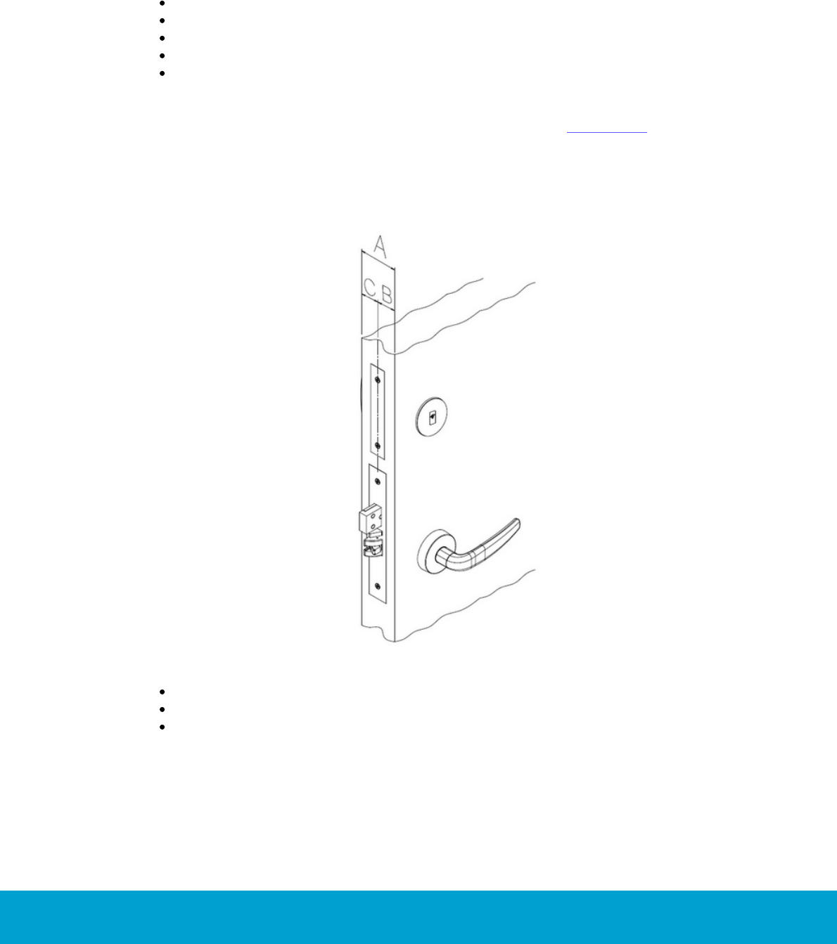
Figure 2: A-, B- and C-dimensions
The A-dimension is the entire door thickness.
The B-dimension is from the outside door edge to the center of the lock case.
The C-dimension is from the inside door edge to the center of the lock case.
9
ASSA ABLOY Hospitality 66 1000 023-2
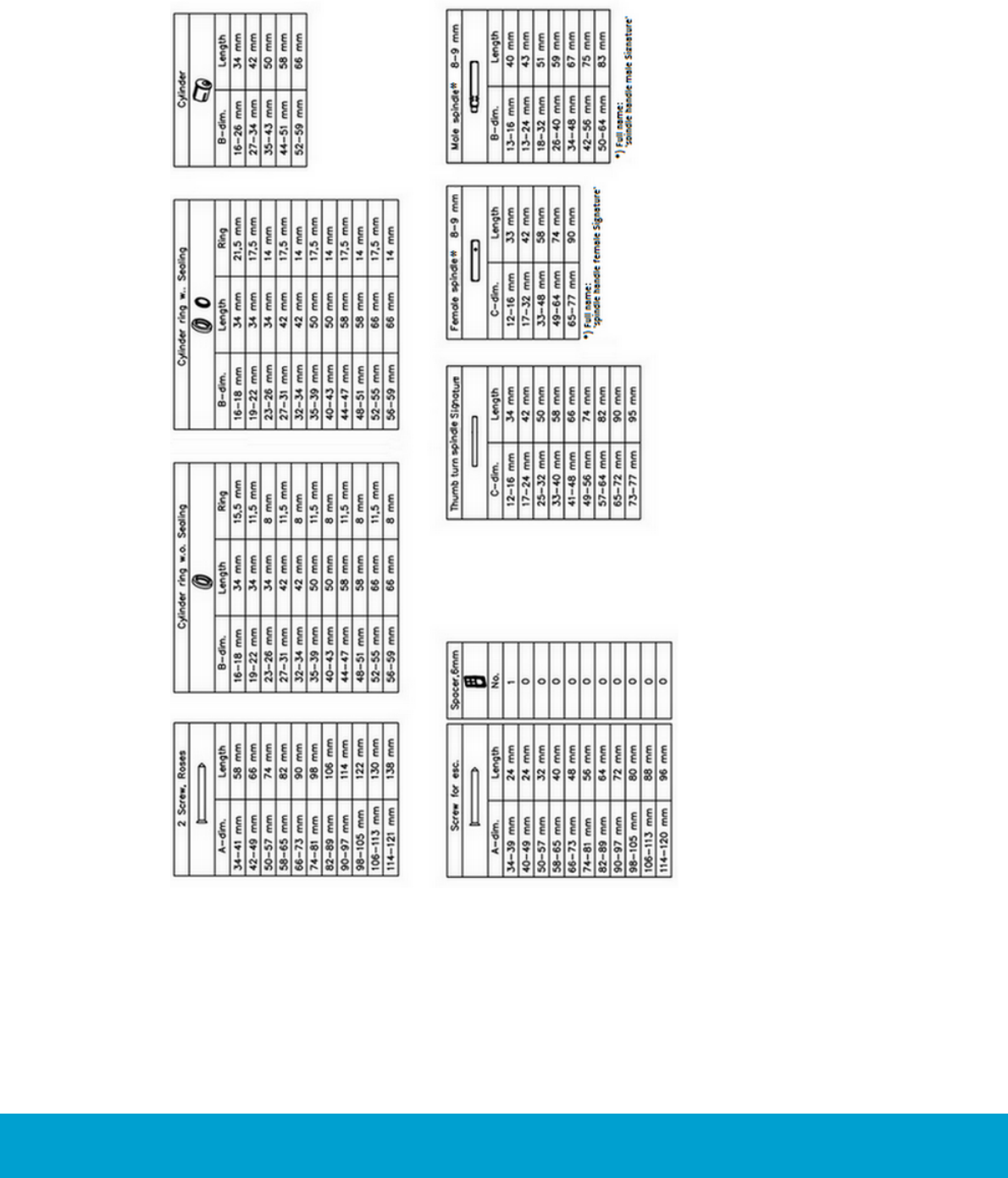
The A-, B- and C-dimensions are important to know when ordering VingCard Essence (v2)
or certain parts for it. See Appendix A: Part dimensions table for Signature/Essence
for detailed information about length of screws, spindles etc according to the A-, B-
and C-dimensions.
Minimum door thickness:
A-Dimension
B-Dimension
38 mm; 1.50"
16 mm; 0.63"
Table 1: Minimum door dimensions; applicable for all ANSI types and all EURO types
Maximum door thickness:
A-Dimension
B-Dimension
129 mm; 5.087"
56 mm; 2.205"
Table 2: Maximum door dimensions; applicable for all ANSI types and all EURO types
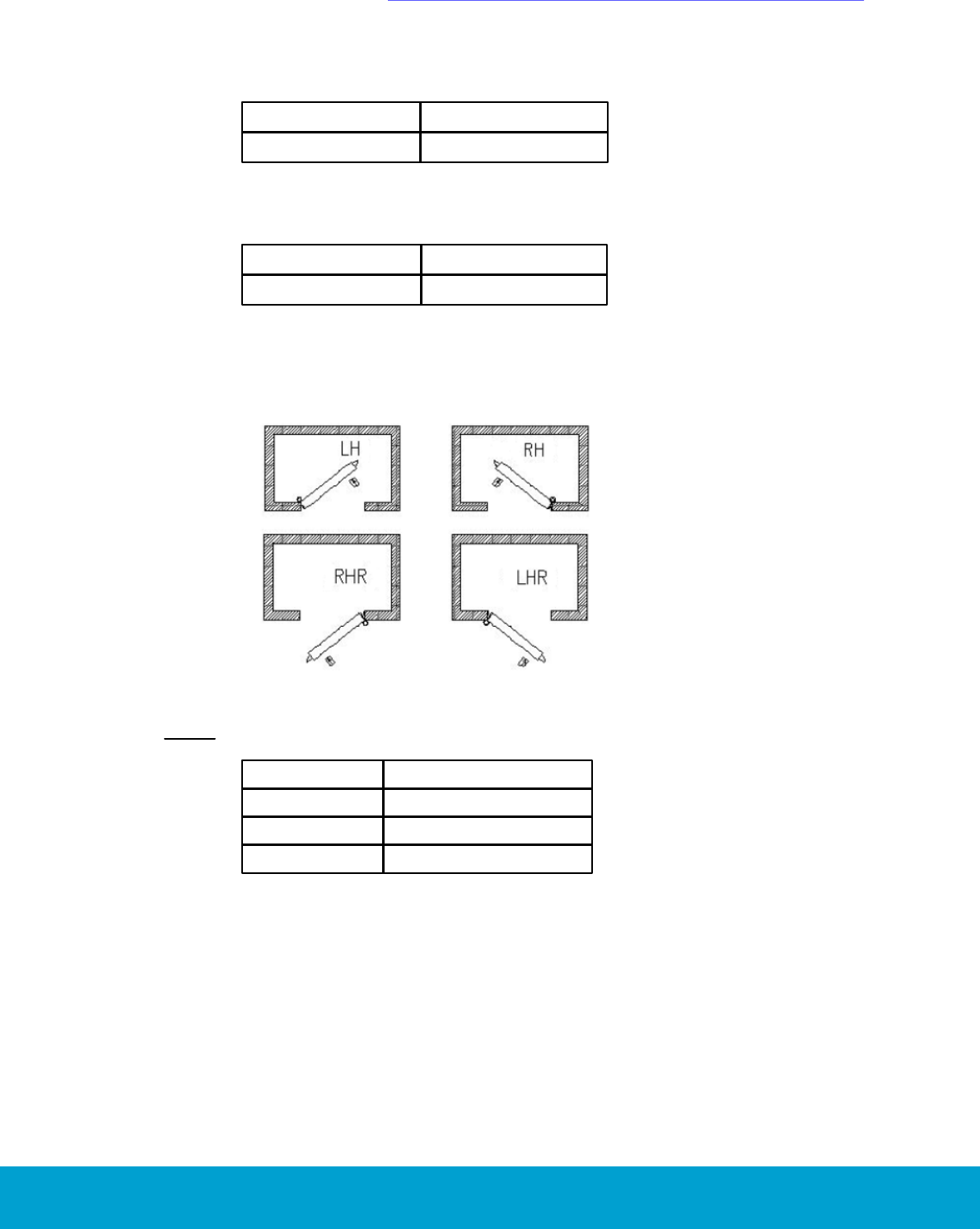
2.2 Door handing
Figure 3: Door handing; for explanation, see Table 3 below.
Note: Always make sure to have the correct handing for all doors.
LH
Left handle
RH
Right handle
RHR
Right handle, retract
LHR
Left handle, retract
Table 3: Explanation of door handing abbreviations
10
ASSA ABLOY Hospitality 66 1000 023-2
2.3 Type of lock case to be ordered (EURO/ANSI)
Always take the A-dimension in account for the
type of lock case to be ordered. Find out which
standard (ANSI or EURO) that applies for the
property. If the door already has a cut-out,
check if the width and shape of the lock front
fit any of the standard ANSI or EURO lock
front dimensions.
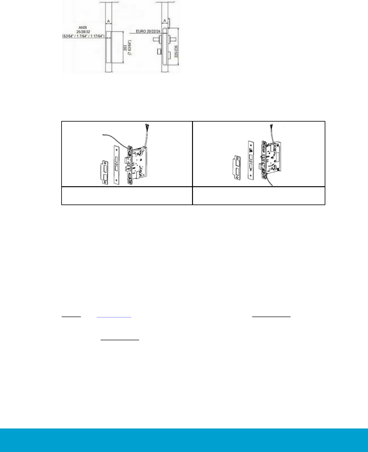
Figure 4: Available heights and widths for ANSI and EURO lock cases
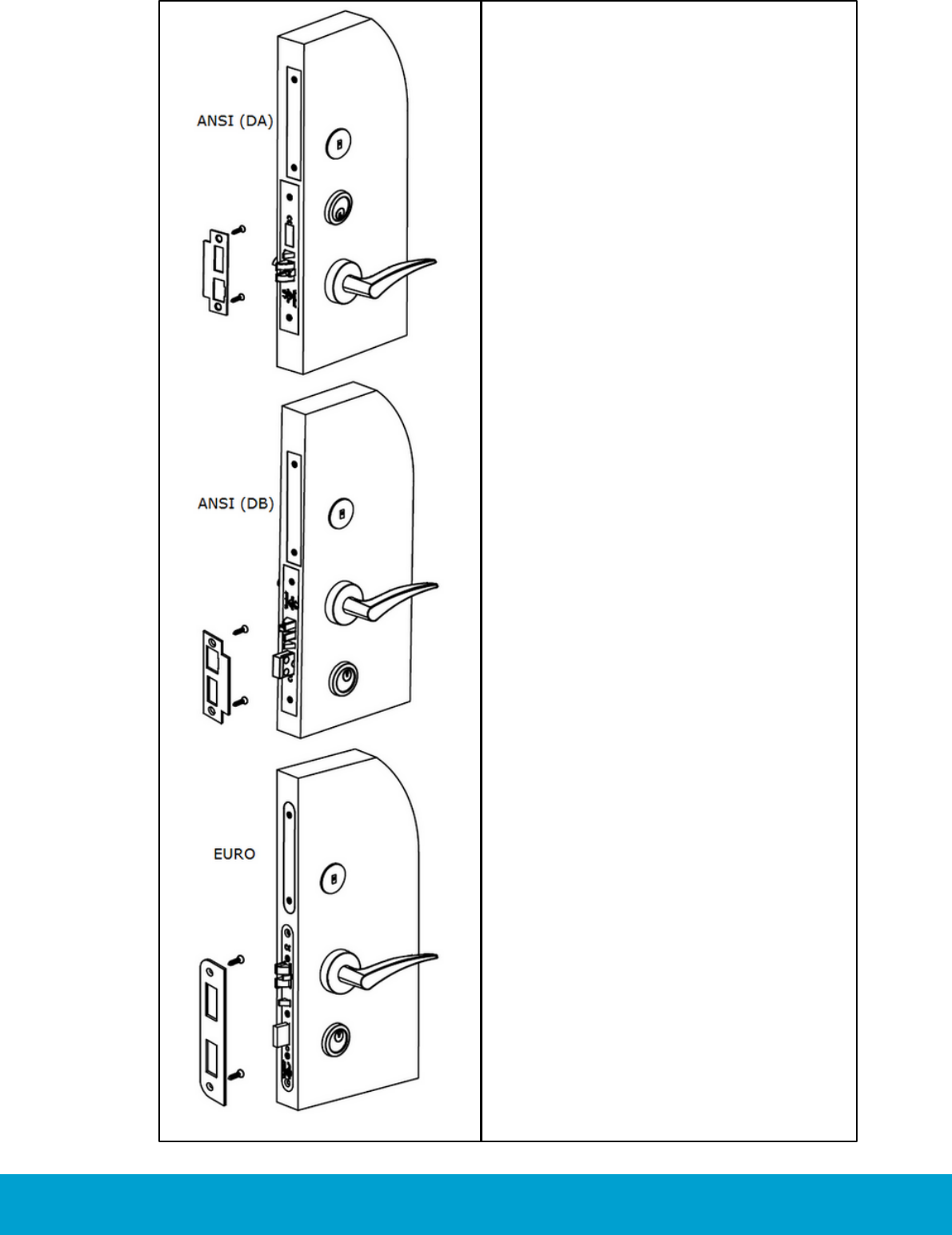
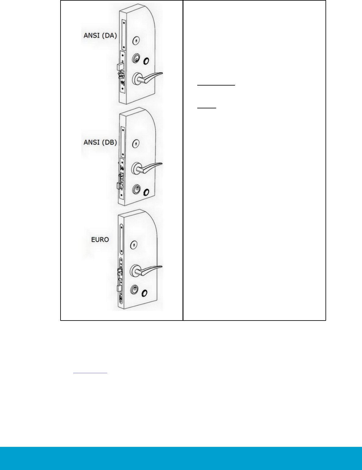
2.3.1 ANSI lock case orientation
Figure 5: ANSI (DA) lock case;
the Dead-bolt is Above the latch.
Figure 6: ANSI (DB) lock case;
the Dead-bolt is Below the latch.
2.4 Dimension requirements
Check the following dimension requirements:
1. The gap between lock front cover and striker plate must not exceed 3 mm; 0.118".
2. For all types of ANSI lock cases, allow at least 25.4 mm (1") depth behind the
striker plate hole for the deadbolt. (Except ANSI AUS = 0 mm and ANSI JPN =
21 mm). Allow 21 mm for EURO lock cases.
3. For all types of ANSI lock cases, allow at least 19 mm (0.748") depth behind the
striker plate hole for the latch. Allow 14 mm for EURO lock cases.
4. Make sure that the lock case, door handles or cylinder does not get in conflict
with i.e. glass windows or ornaments/decor on the door.
Note: See section 3.1 for an overview of available cut-outs. Important: The hole for
the cylinder is optional and is only to be cut out for locks equipped with cylinders and
only from the outside of the door to the center of the lock case; i.e. not through the
entire door. Important: If you are going to install the security cylinder Hydra,
remember to make space for the cylinder fastening clip when making the cut-out
for the lock case.
11
ASSA ABLOY Hospitality 66 1000 023-2
2.5 Check the door frames/striker plates
Check if you can use ANSI or EURO standard striker plate or if you need to order a
customized striker plate. Check if the door frame is a wooden frame or a steel frame.
This will decide what kind of tools you will need for the installation.
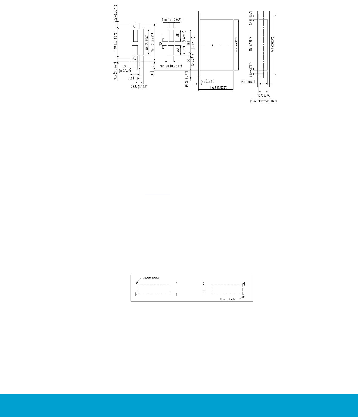
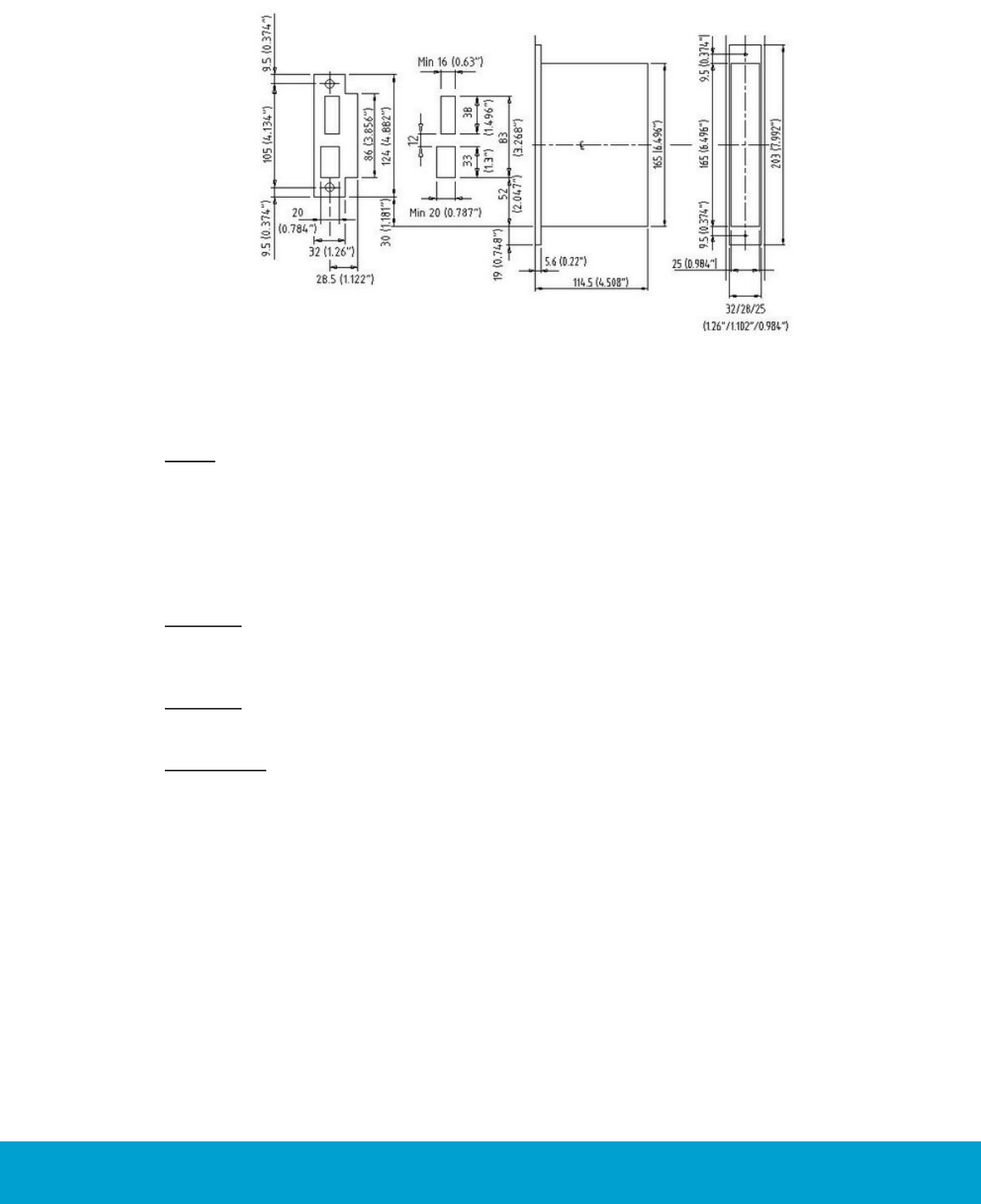
Figure 7: Positioning of ANSI (DA) standard striker plate.
Note the dimension 30 mm (1.181") from the edge
of the lock case to the edge of the striker plate.
Figure 7 above shows the lock case center line (CL); see dot and dash line through the
figure above. The CL is important for the positioning of the lock case, striker plate and
escutcheon onto the doors.
Position of the ANSI standard striker plate:
The striker plate is positioned in the frame so that the bottom of the striker plate
is 30 mm (1.18'') above the bottom of the lock case; see Figure 7. Horizontally,
the B- or C-dimension (see Figure 2) will apply depending on the direction of
the door and the center/rebate orientation.
Note: Be aware if there is any door gasket.
2.6 Beveled doors
If the door is beveled (edge is not at 90º to door), the dimensions should be based
on the shortest side. Standard beveling is 3.2 mm; 1/8".
Figure 8: Beveled doors
12
ASSA ABLOY Hospitality 66 1000 023-2
2.7 Rebated doors
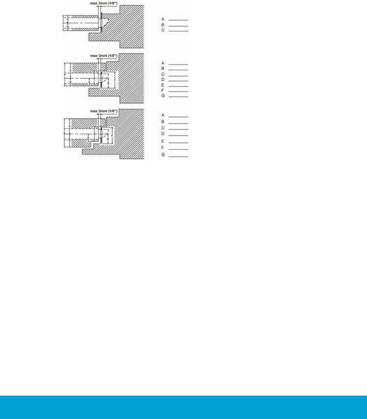
When it comes to rebated doors and rebated frames, be extra observant regarding
protrusion for the deadbolt on the frame side. See Figure 9 for examples of rebated
doors and door frames.
Figure 9: Examples of rebated doors
and door frames
13
ASSA ABLOY Hospitality 66 1000 023-2
3. To mortise the door
Before installing the lock in the door, the door and door frame must be mortised
to fit this type of lock. The mortising should be based on the dimensions shown
in the applicable cut-out; see section 3.1 for an overview of available cut-outs.
The position of the lock case (lock case center line) has to be set according to
the ANSI standard and be level from the floor. American Disabilities Act (ADA)
requirements demand a maximum of 1220 mm (48") height to the highest point
of operation.
3.1 Cut-outs
The following cut-outs are available:
Description
Online/offline
Document number
ANSI (DA) with cylinder
Online
AN-236
ANSI (DA) with cylinder
Offline
AN-244
ANSI (DA) without cylinder
Online
AN-238
ANSI (DA) without cylinder
Offline
AN-243
ANSI (DB) with cylinder
Online
AN-241
ANSI (DB) without cylinder
Online
AN-239
EURO with cylinder
Online
AN-242
EURO without cylinder
Online
AN-240
Table 4
14
ASSA ABLOY Hospitality 66 1000 023-2
3.2 To mortise for the lock case
Determine where the positioning of the lock case center line (CL) shall be, and make
the cut-out according to Figure 10.
Figure 10: Cut-out for
ANSI (DA) lock case
Important: The lock front can be delivered with a width of 32 mm (1.26"), 28 mm
(1.102") or 25 mm (0.984"). Make sure that you mortise the door to the correct
dimensions for your lock dimensions. Check the dimensions of the lock before you
start cutting.
Important: If you are going to install the security cylinder Hydra, remember to
make space for the cylinder fastening clip when making the cut-out for the lock case.
3.2.1 Tools needed to make the cut-out for the lock case
Hammer and chisel are needed to make the corners for the lock front.
15
ASSA ABLOY Hospitality 66 1000 023-2
3.3 To mortise for the striker plate
Figure 11: External striker plate dimensions and
cut-out dimensions for ANSI (DA).
Note: Be aware of the dimension 30 mm (1.181'') from the edge of the lock case to
the edge of the striker plate.
Before mortising for the striker plate, make sure to align the side template vertically
and horizontally according to Figure 11. Use the center line (CL) for the lock case as
a reference. Position the striker plate so that the bottom of the striker plate is 30 mm
(1.18") above the bottom of the lock case.
Caution: If the cut-out for the deadbolt is less than 25.4 mm (1") deep, the deadbolt
may not be retracted by use of a metal key in case of an emergency when the door is
double locked (ANSI AUS = 0, ANSI JPN = 21).
Caution: Be aware if there is any door gasket. If so, compensation must be made by
adjusting the horizontal positioning of the striker plate.
Important: If the striker plate is not used (example: steel frame), it is important
that the distance between the latch (lower) cut-out and the deadbolt cut-out must
be 12 mm (0,47") in order for the auxiliary latch to work.
3.3.1 Tools needed to make the cut-out for the striker plate
Use an ordinary drilling machine, hammer and chisel.
16
ASSA ABLOY Hospitality 66 1000 023-2
4. To install the lock
4.1 Necessary tools for the installation
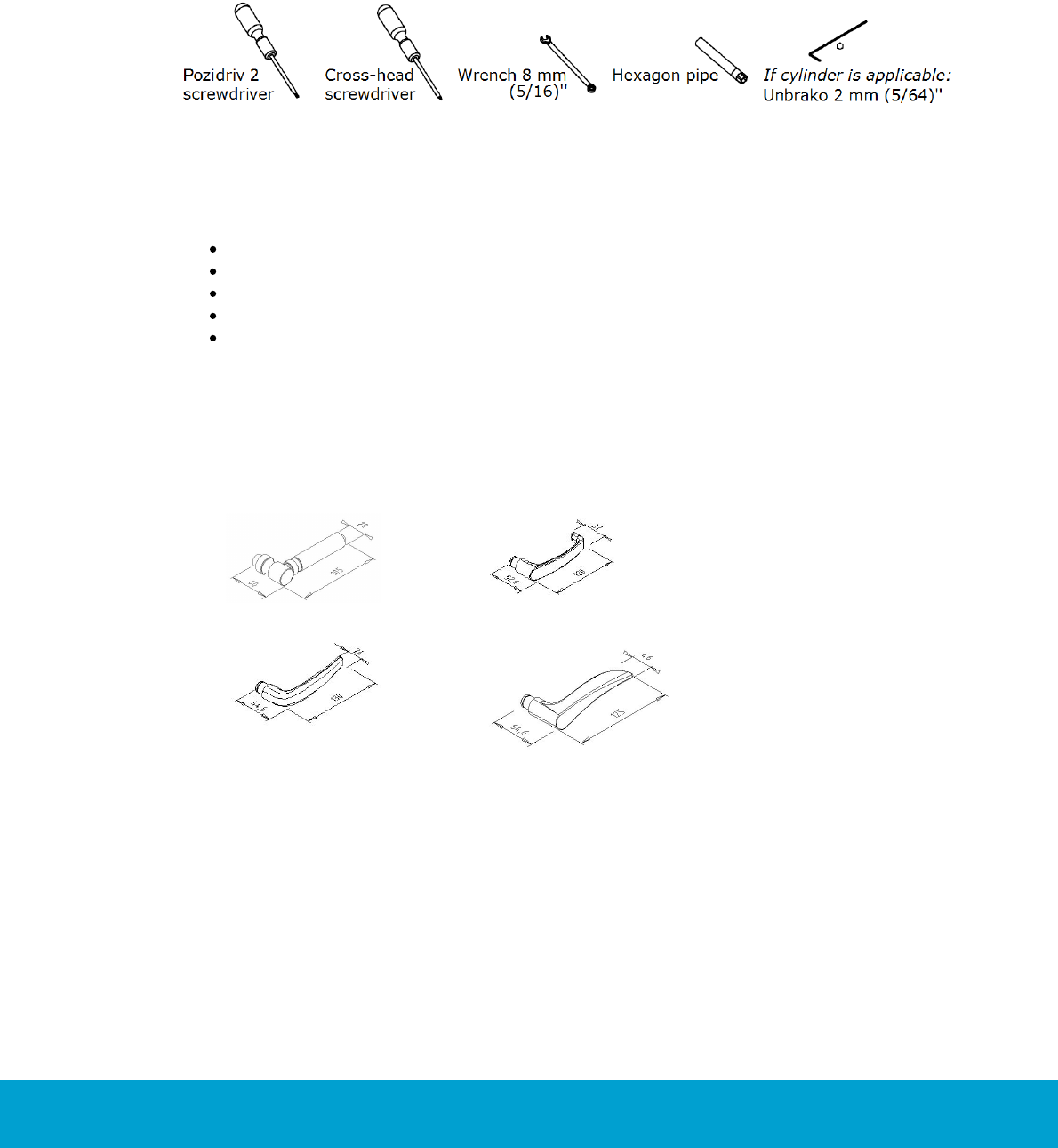
Figure 12: Tools needed for installing the lock;
the Unbrako is only needed if cylinder is applicable
The tools shown in Figure 12 are needed for assembly of the lock:
Pozidriv 2 screwdriver
Cross-head screwdriver
Wrench 8 mm (5/16)''
Hexagon pipe
If cylinder is applicable: Unbrako 2 mm (5/64)''; only used to fasten the
cylinder fastening screw
4.2 Door handle selection
It is possible to choose between a variety of standard door handles and a variety
of door handles from the Designers Collection from Valli & Valli.
Gothic
ANSI
Straight
Wing
Figure 13: Standard Essence door handles
17
ASSA ABLOY Hospitality 66 1000 023-2
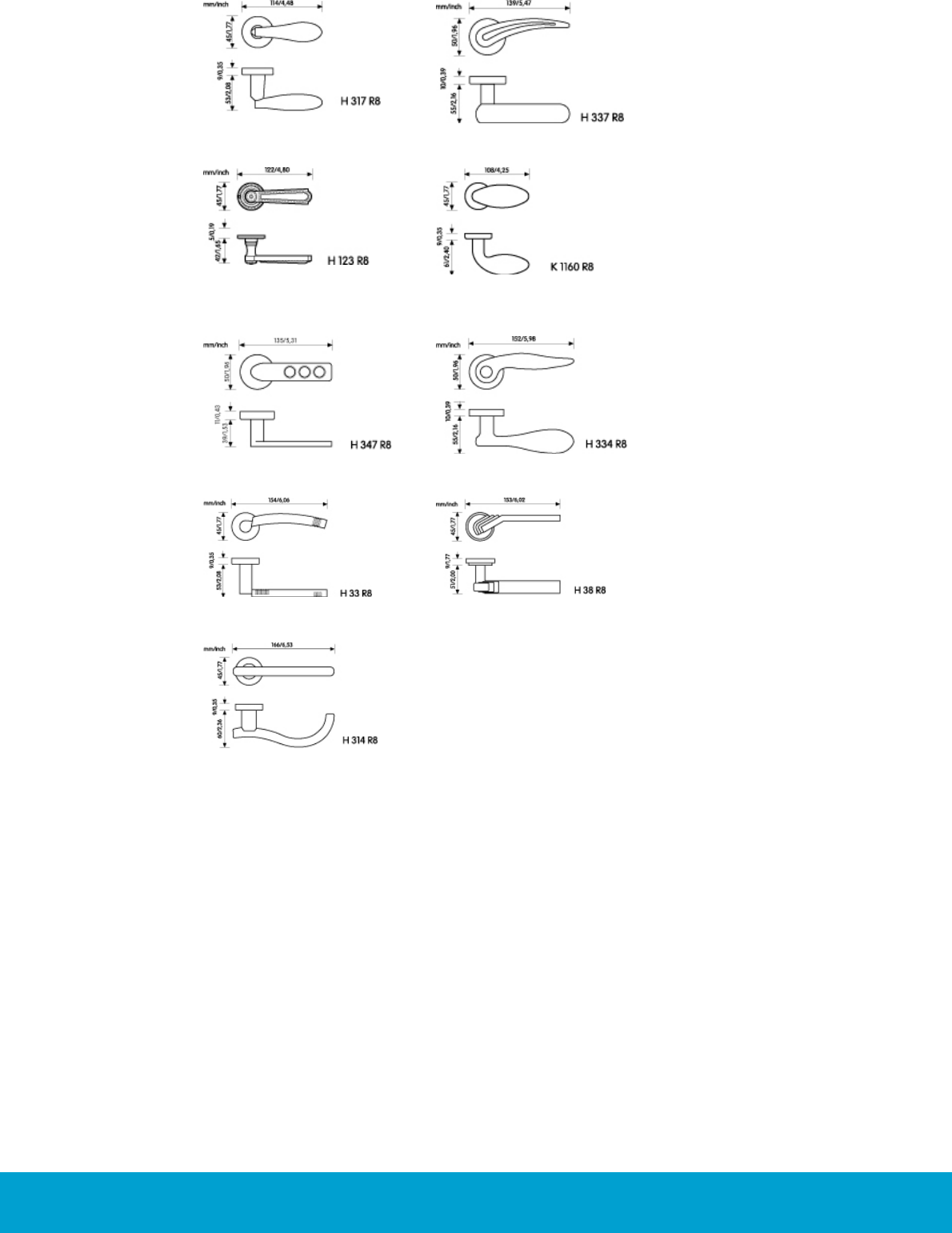
AC Nonvantuno
GP Novantotto
H123 R8 (Valli &
Valli)
K1160 R8 (Valli & Valli)
MDF Duemiladue
NF Novantotto
Quattro S
Quattro S
S Novanta
Figure 14: Door handles from the Designers Collection from Valli &Valli
18
ASSA ABLOY Hospitality 66 1000 023-2
4.3 Exploded view
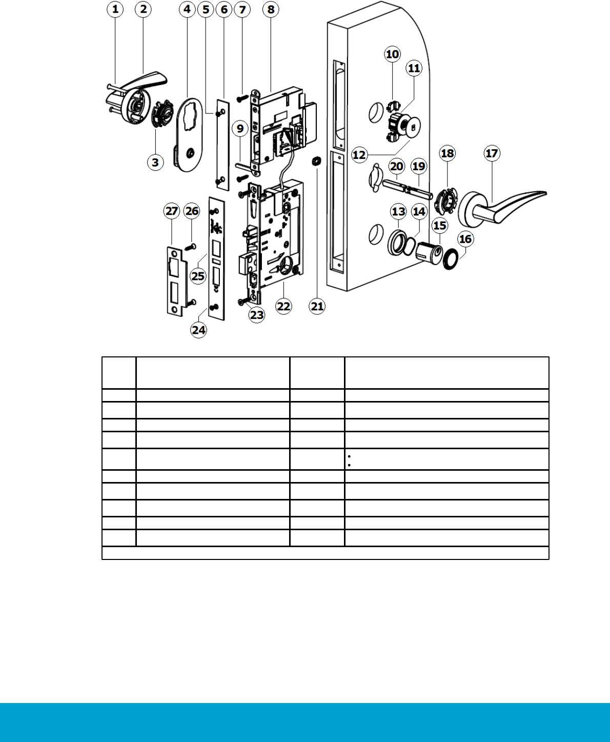
4.3.1 ANSI (DA)
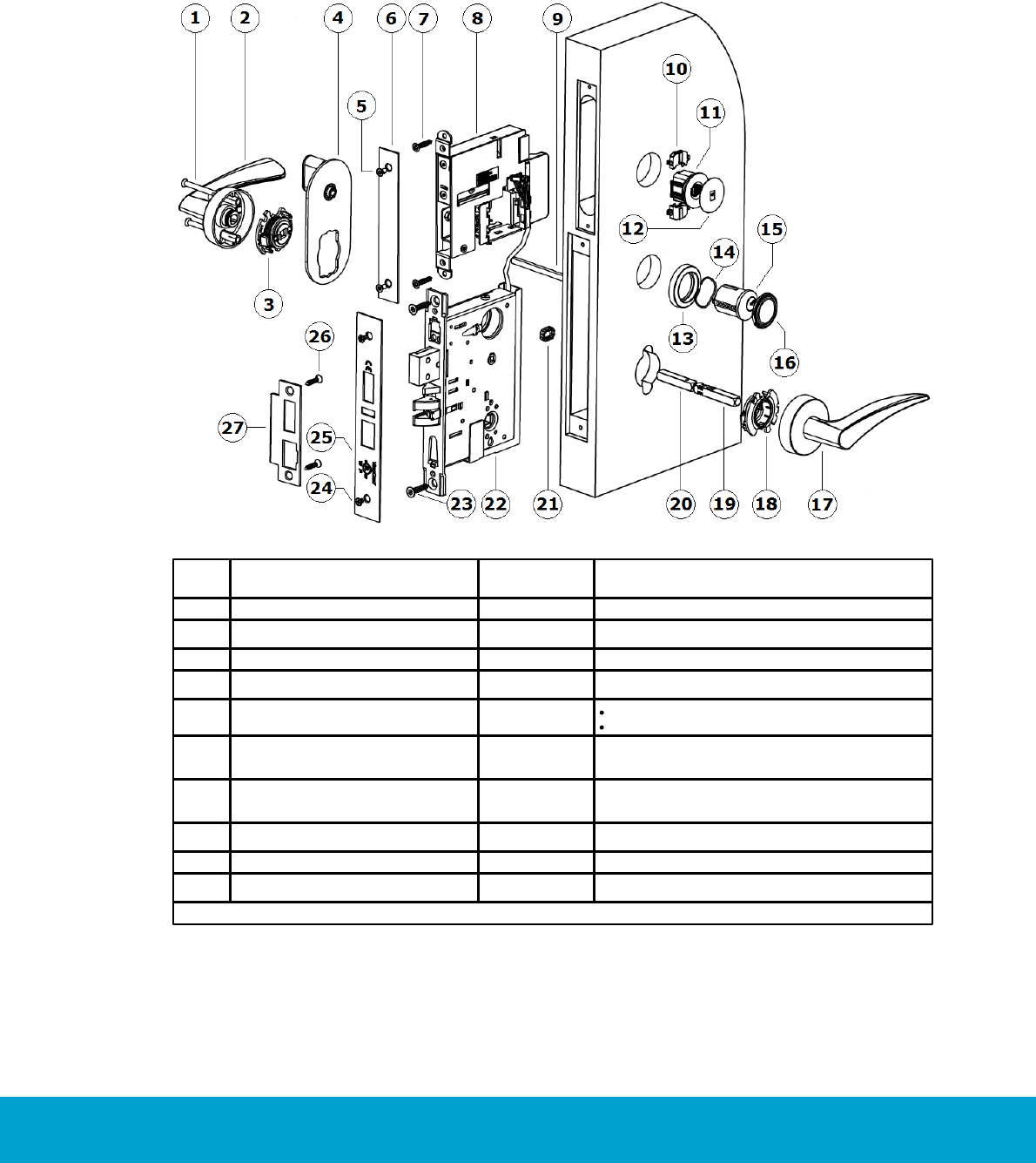
Figure 15: Components for a VingCard Essence (v2) lock, ANSI (DA) variant with cylinder
Pos
Description
Available as
single item
Available as kit
1
Screw Signature M5
X
HW kit Essence/Sig 1000-series
2
Handle on inside rose Signature
X
3, 18
Handle retainer*Signature
X
HW kit Essence/Sig 1000-series
4
Escutcheon thumbturn Signature
X
5
Screw, M4x5
X
Front end kit, square, for Essence
Screw kit for ANSI lock case, brass & chrome
6
Front for Essence cassette
X
Front end kit, square, for Essence cassette
7
Screw 4,5 x 22
Front end kit, square, for Essence cassette
8
Essence cassette
X
VingCard Essence (v2) main assembly
9
Thumbturn spindle Signature
X
HW kit Essence/Sig 1000-series
10
Spacer
X
VingCard Essence (v2) main assembly
Table is continued on next page

19
ASSA ABLOY Hospitality 66 1000 023-2
Pos
Description
Available as
single item
Available as kit
11
LCU 5350
X
VingCard Essence (v2) main assembly
12
Service cover
X
VingCard Essence (v2) main assembly
13
Cylinder rose
X
Cylinder ring kit Signature
14
Spring cylinder rose Signature
X
Cylinder ring kit Signature
15
Cyl 5-lev Std thread front prof R
X
Cyl 5-lev A ADB thread front prof R
X
Cyl 5-lev E ADB thread front prof R
X
16
Cylinder sealing assy
X
Cylinder ring kit Signature [finish] XXmm w/seal
17
Handle on outside rose Signature
X
18
See 3, 18
X
HW kit Essence/Sig 1000-series
19
Spindle handle male Signature
X
Square spindle assy Signature *)
20
Spindle handle female Signature
X
Square spindle assy Signature *)
21
Spindle locking clip
X
HW kit Essence/Sig 1000-series
22
Lock case ANSI DA
X
Lock case ANSI DA ADB
X
23
Screw wood, countersunk 5X25 mm
X
Screw kit for ANSI lock case, brass & chrome
24
Screw, M4x5
X
Front end kit, square, for Essence cassette
Screw kit for ANSI lock case, brass & chrome
25
Lock front ANSI
X
Lock front ANSI ADB
X
26
Screw 5,00x12 st 4,8 Zinc color
Screw kit for ANSI lock case, brass & chrome
Screw 5,00x12 st 4,8 Yellow color
Screw kit for ANSI lock case, brass & chrome
Screw, wood, countersunk, 5x25mm,
Metal zinc color
Screw kit for ANSI lock case, brass & chrome
Screw, wood, countersunk, 5x25mm,
Metal yellow color
Screw kit for ANSI lock case, brass & chrome
27
Striker plate ANSI
X
Striker plate ANSI ADB
X
Table 5
*) 'Square spindle assy Signature’ is sold as a separate kit, but is also included in 'HW kit Essence/Sig 1000-series'.
20
ASSA ABLOY Hospitality 66 1000 023-2
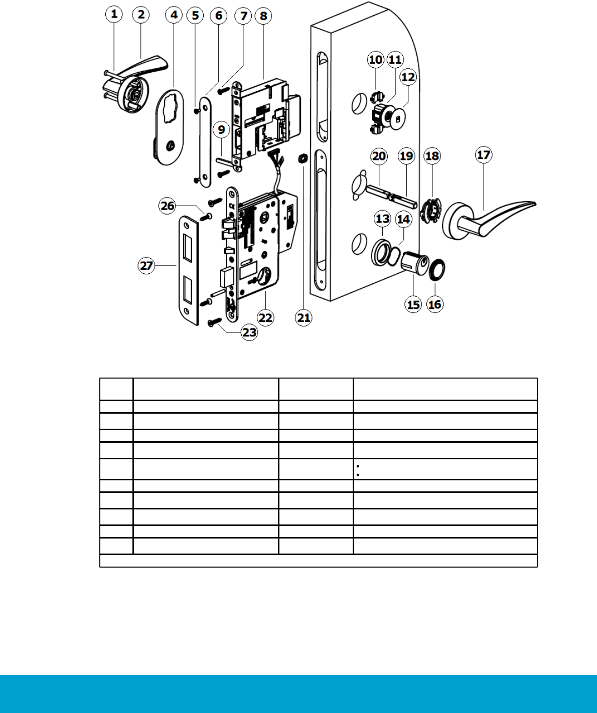
4.3.2 ANSI (DB)
Figure 16: Components for a VingCard Essence (v2) lock, ANSI (DB) variant with cylinder
Pos
Description
Available
as
single item
Available as kit
1
Screw Signature M5
X
HW kit Essence/Sig 1000-series
2
Handle on inside rose Signature
X
3, 18
Handle retainer*Signature
X
HW kit Essence/Sig 1000-series
4
Escutcheon thumbturn Signature
X
5
Screw, M4x5
X
Front end kit, square, for Essence
Screw kit for ANSI lock case, brass & chrome
6
Front for Essence cassette
X
Front end kit, square, for Essence cassette
7
Screw 4,5 x 22
Front end kit, square, for Essence cassette
8
Essence cassette
X
VingCard Essence (v2) main assembly
9
Thumbturn spindle Signature
X
HW kit Essence/Sig 1000-series
10
Spacer
X
VingCard Essence (v2) main assembly
Table is continued on next page

21
ASSA ABLOY Hospitality 66 1000 023-2
Pos
Description
Available
as
single item
Available as kit
11
LCU 5350
X
VingCard Essence (v2) main assembly
12
Service cover
X
VingCard Essence (v2) main assembly
13
Cylinder rose
X
Cylinder ring kit Signature
14
Spring cylinder rose Signature
X
Cylinder ring kit Signature
15
Cyl 5-lev Std thread front prof R
X
Cyl 5-lev A ADB thread front prof R
X
Cyl 5-lev E ADB thread front prof R
X
16
Cylinder sealing assy
X
Cylinder ring kit Signature [finish] XXmm w/seal
17
Handle on outside rose Signature
X
18
See 3, 18
X
HW kit Essence/Sig 1000-series
19
Spindle handle male Signature
X
Square spindle assy Signature *)
20
Spindle handle female Signature
X
Square spindle assy Signature *)
21
Spindle locking clip
X
HW kit Essence/Sig 1000-series
22
Lock case ANSI DB
X
Lock case ANSI DB ADB
X
23
Screw wood, countersunk 5X25 mm
X
Screw kit for ANSI lock case, brass & chrome
24
Screw, M4x5
X
Front end kit, square, for Essence cassette
Screw kit for ANSI lock case, brass & chrome
25
Lock front ANSI
X
Lock front ANSI ADB
X
26
Screw 5,00x12 st 4,8 Zinc color
Screw kit for ANSI lock case, brass & chrome
Screw 5,00x12 st 4,8 Yellow color
Screw kit for ANSI lock case, brass & chrome
Screw, wood, countersunk, 5x25mm,
Metal zinc color
Screw kit for ANSI lock case, brass & chrome
Screw, wood, countersunk, 5x25mm,
Metal yellow color
Screw kit for ANSI lock case, brass & chrome
27
Striker plate ANSI
X
Striker plate ANSI ADB
X
Table 6
*) 'Square spindle assy Signature’ is sold as a separate kit, but is also included in 'HW kit Essence/Sig 1000-series'.
22
ASSA ABLOY Hospitality 66 1000 023-2
4.3.3 EURO
Figure 17: Components for a VingCard Essence (v2) lock, EURO variant with cylinder
Pos
Description
Available as
single item
Available as kit
1
Screw Signature M5
X
HW kit Essence/Sig 1000-series
2
Handle on inside rose Signature
X
3, 18
Handle retainer*Signature
X
HW kit Essence/Sig 1000-series
4
Escutcheon thumbturn Signature
X
5
Screw, M4x5
X
Front end kit, square, for Essence
Screw kit for ANSI lock case, brass & chrome
6
Front for Essence cassette
X
Front end kit, square, for Essence cassette
7
Screw 4,5 x 22
Front end kit, square, for Essence cassette
8
Essence cassette
X
VingCard Essence (v2) main assembly
9
Thumbturn spindle Signature
X
HW kit Essence/Sig 1000-series
10
Spacer
X
VingCard Essence (v2) main assembly
Table is continued on next page

23
ASSA ABLOY Hospitality 66 1000 023-2
Pos
Description
Available as
single item
Available as kit
11
LCU 5350
X
VingCard Essence (v2) main assembly
12
Service cover
X
VingCard Essence (v2) main assembly
13
Cylinder rose
X
Cylinder ring kit Signature
14
Spring cylinder rose Signature
X
Cylinder ring kit Signature
15
Cyl 5-lev Std thread front prof R
X
Cyl 5-lev A ADB thread front prof R
X
Cyl 5-lev E ADB thread front prof R
X
16
Cylinder sealing assy
X
Cylinder ring kit Signature [finish] XXmm w/seal
17
Handle on outside rose Signature
X
18
See 3, 18
X
HW kit Essence/Sig 1000-series
19
Spindle handle male Signature
X
Square spindle assy Signature *)
20
Spindle handle female Signature
X
Square spindle assy Signature *)
21
Spindle locking clip
X
HW kit Essence/Sig 1000-series
22
Lock case EURO
X
Lock case EURO ADB
X
23
Screw wood, countersunk 5X25 mm
X
Screw kit for ANSI lock case, brass & chrome
24
Not applicable for EURO
25
Not applicable for EURO
26
Screw 5,00x12 st 4,8 Zinc color
Screw kit for ANSI lock case, brass & chrome
Screw 5,00x12 st 4,8 Yellow color
Screw kit for ANSI lock case, brass & chrome
Screw, wood, countersunk, 5x25mm,
Metal zinc color
Screw kit for ANSI lock case, brass & chrome
Screw, wood, countersunk, 5x25mm,
Metal yellow color
Screw kit for ANSI lock case, brass & chrome
27
Striker plate EURO
X
Table 7
*) 'Square spindle assy Signature’ is sold as a separate kit, but is also included in 'HW kit Essence/Sig 1000-series'.
24
ASSA ABLOY Hospitality 66 1000 023-2
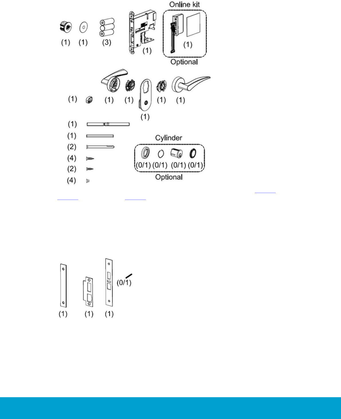
4.4 Parts included for a complete lock
Figure 18: Parts included for a complete Essence lock; see details in Table 6 (ANSI DA),
Table 7 (ANSI DB) and Table 8 (EURO). The online kit and cylinder kit are purchased
separately, when applicable.
4.4.1 ANSI specific parts
The below parts are specific for ANSI (DA) and ANSI (DB); the striker plate is
however turned the other way for ANSI (DB).
Figure 19, from the left: front for Essence cassette, striker plate ANSI,
lock front ANSI and cylinder set screw for cylinders ex threaded ANSI ADB.
25
ASSA ABLOY Hospitality 66 1000 023-2
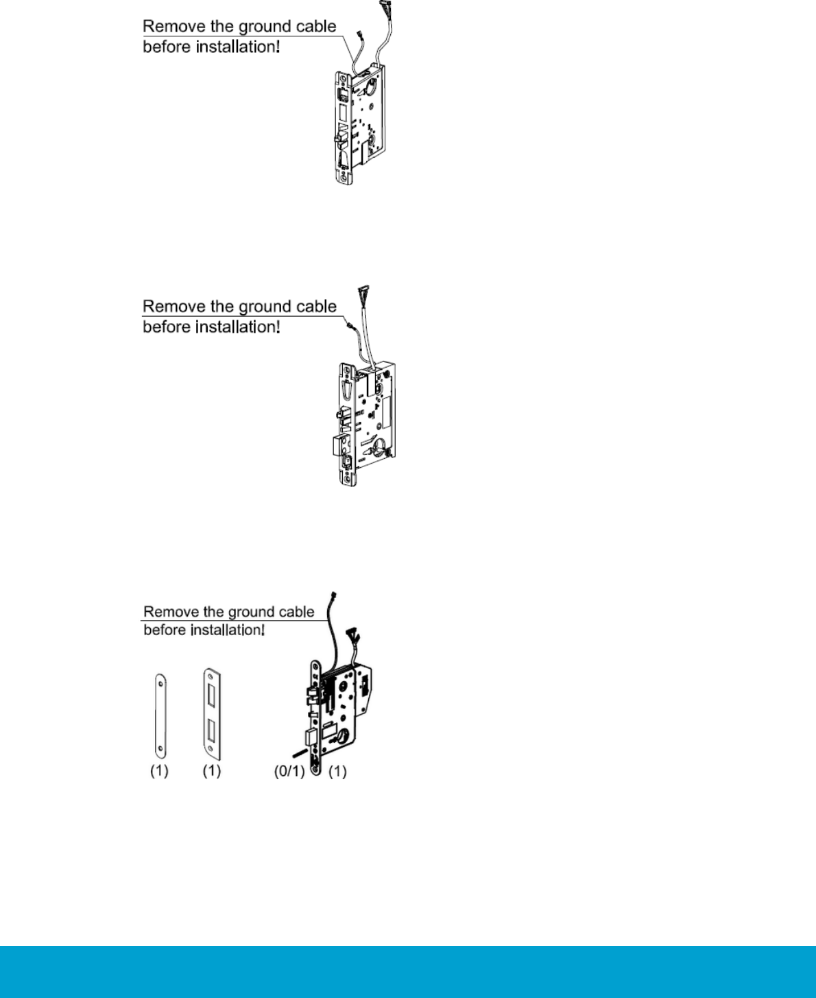
4.4.1.1 ANSI (DA) specific part
Figure 20: The lock case is the only part which is specific for ANSI (DA).
4.4.1.2 ANSI (DB) specific part
Figure 21: The lock case is the only part which is specific for ANSI (DB).
4.4.2 EURO specific parts
Figure 22, from the left: front cover rounded, striker plate EURO 5994 steel,
cylinder set screw for cylinders ex threaded ANSI ADB and lock case EURO.
26
ASSA ABLOY Hospitality 66 1000 023-2
4.5 Installation
Figure 23
Figure 24
Figure 25
Note: For information about online
related parts of the installations,
see Appendix D.
Note: The position numbers in bold refer
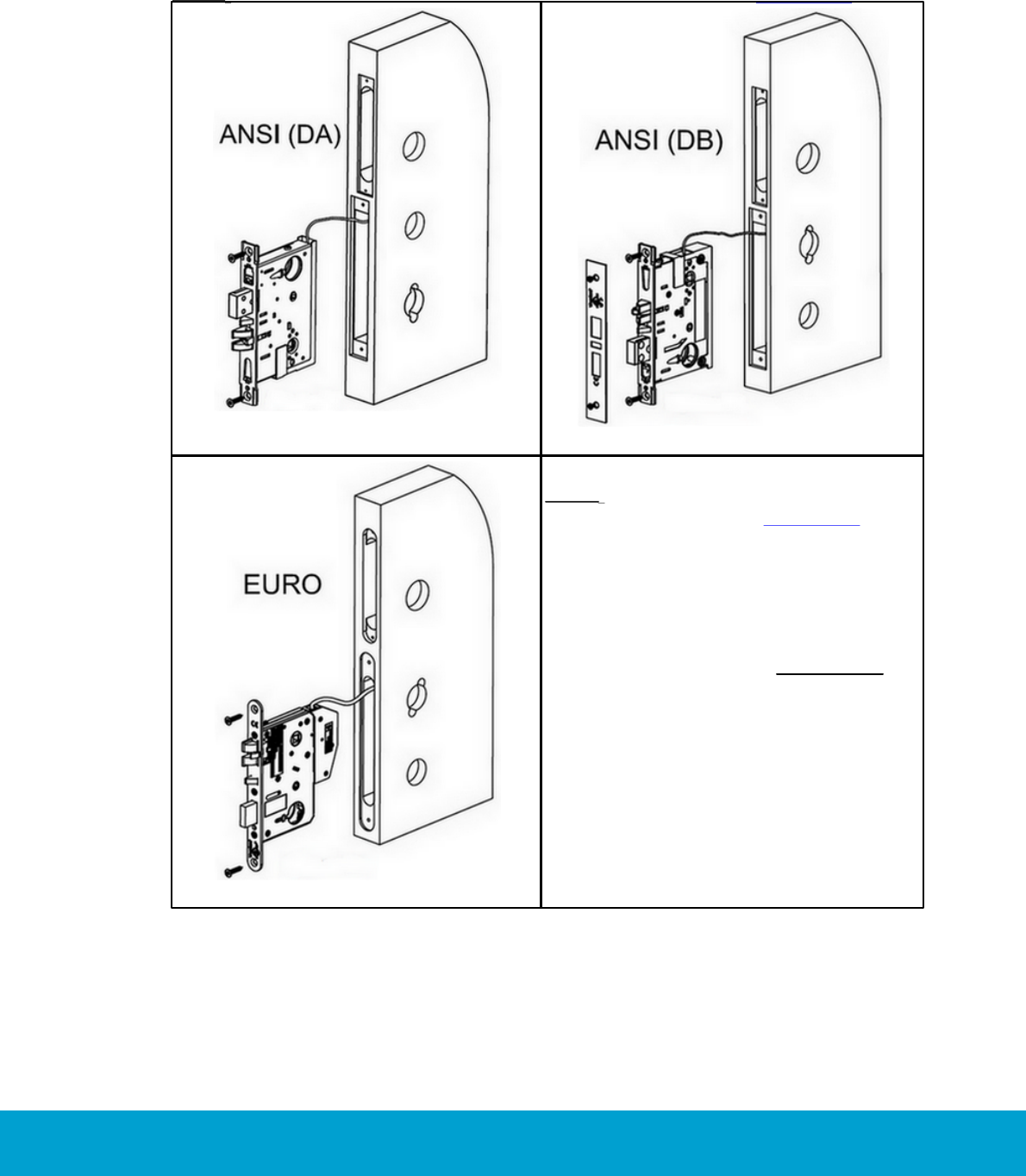
to the exploded views in section 4.3.
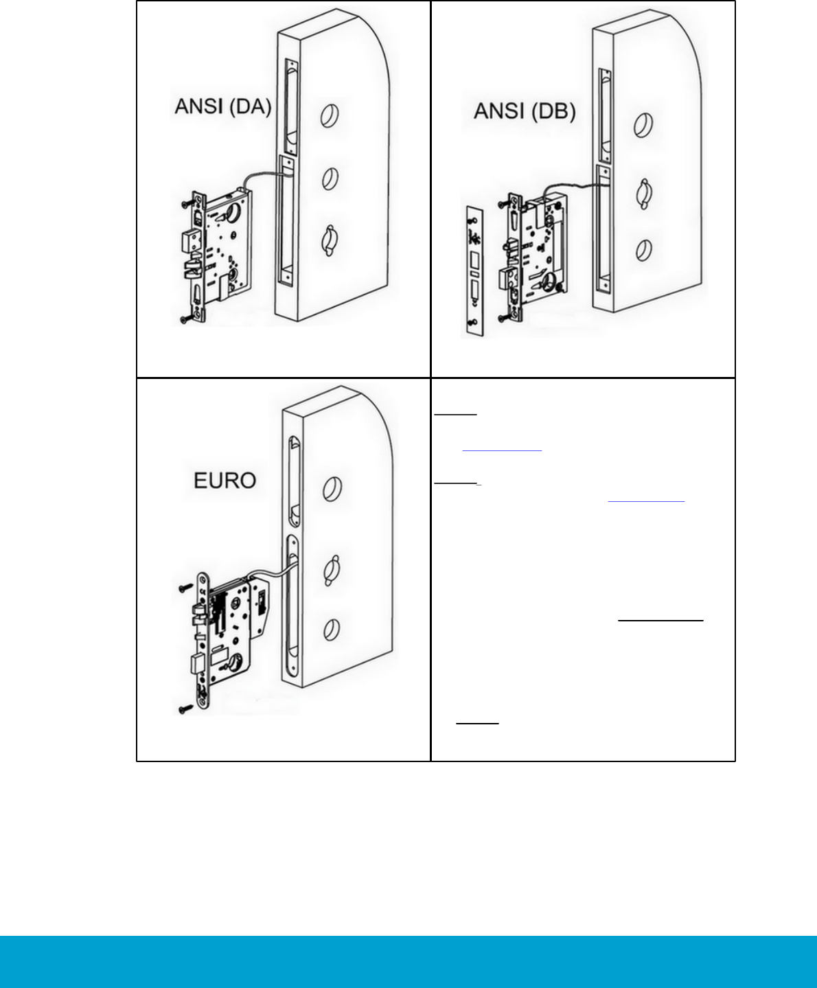
1. Position the cables into the door
before inserting the lock case (22).
The connector on the cable must be
bent before being threaded into the
hole through the door. Important:
Do not lubricate the lock case.
2. Position the lock case into the edge
of the door and fasten it with two
screws wood, countersunk 5X25 mm
(23).
Note: If applicable, do not forget to
install the cylinder fastening clip
before inserting the lock case.
27
ASSA ABLOY Hospitality 66 1000 023-2
Figure 26
Figure 27
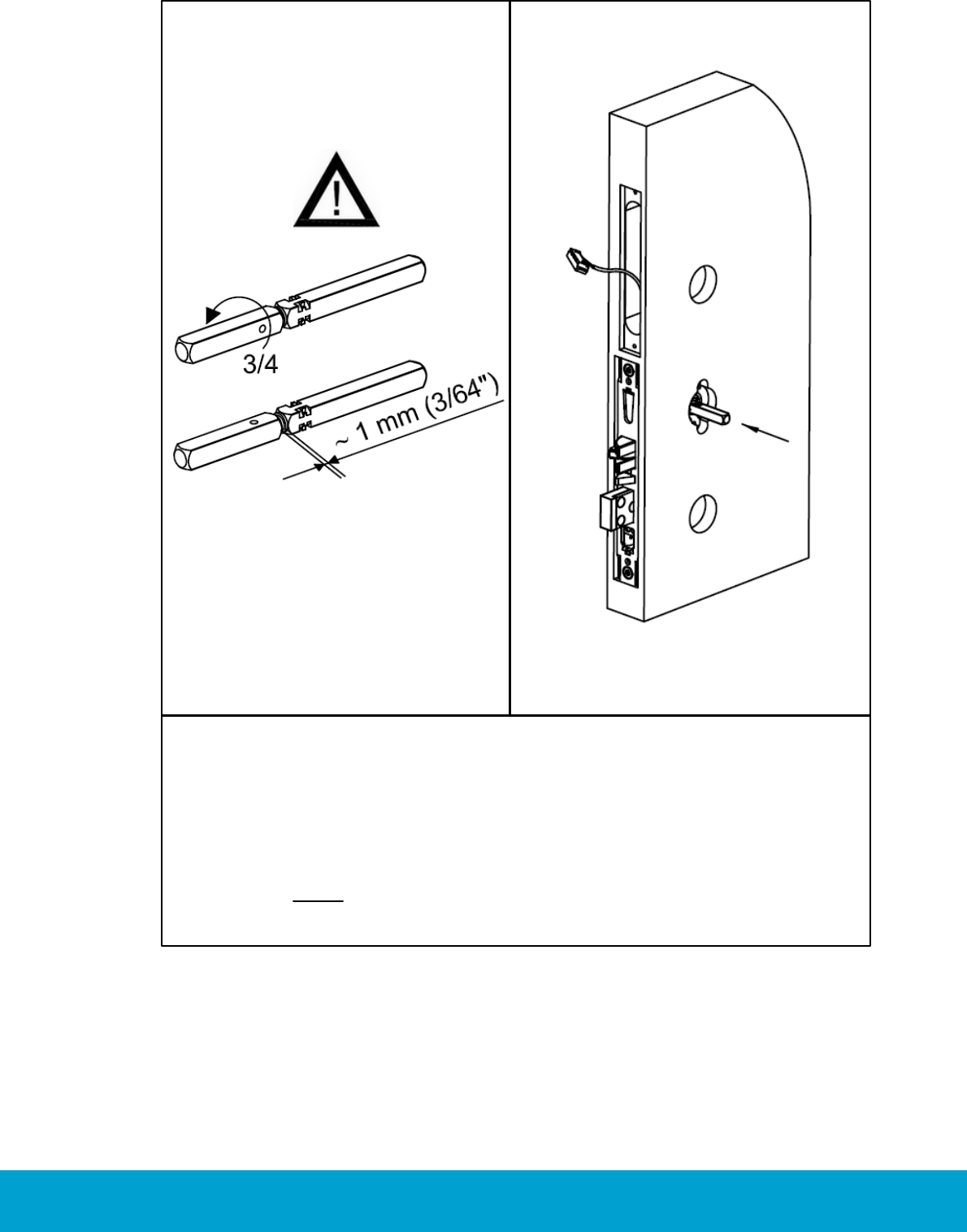
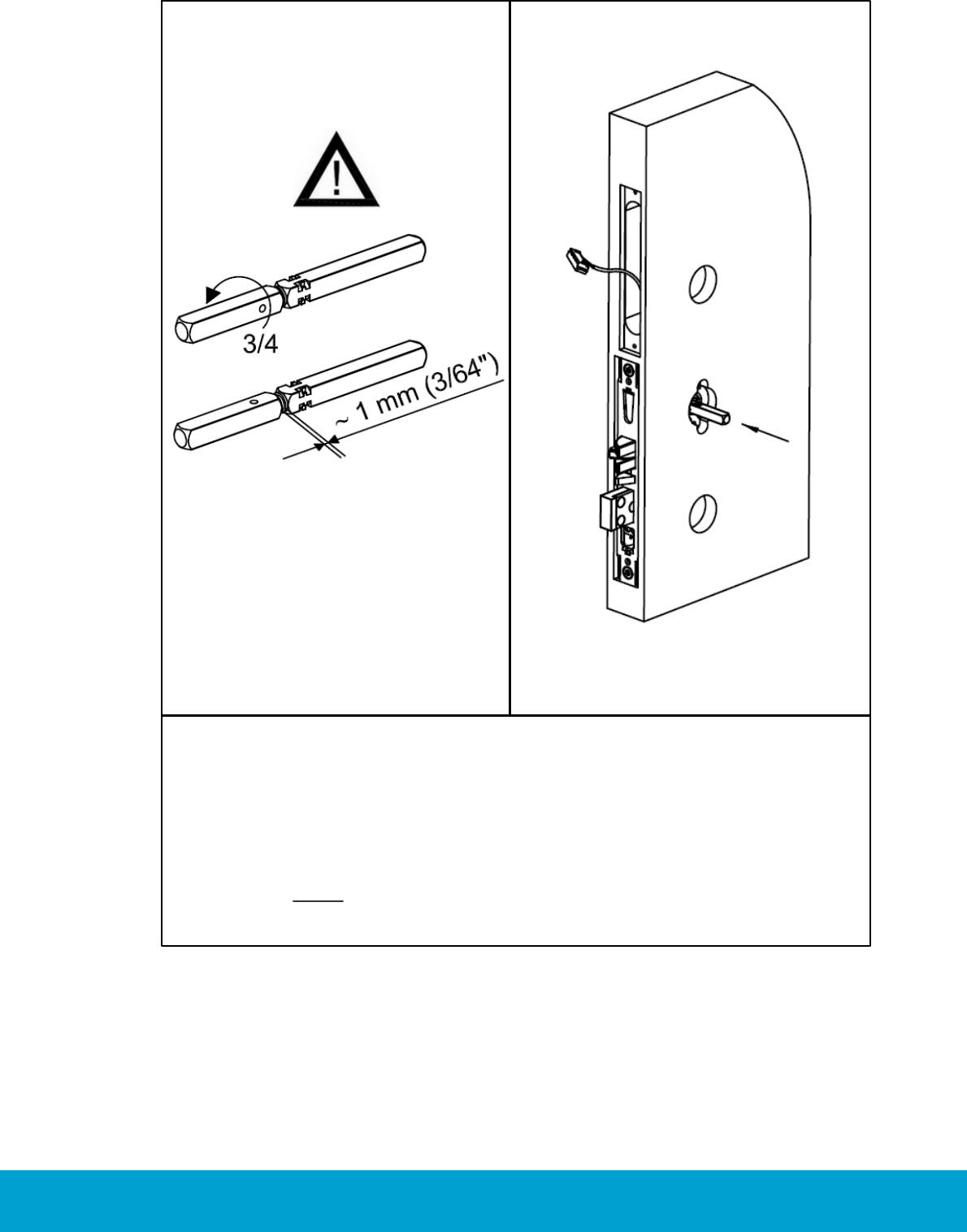
3. Before inserting the spindle handle female Signature (20) and the spindle
handle male Signature (19) into the lock case, check that the spindle threads
are lubricated with grease.
4. Screw the spindle handle female Signature onto the spindle handle male Signature
and then reverse it (3/4 turn).
5. Insert the spindle handles into the lock case from the outside of the door so that
the hole that goes through the spindle handle is visible on the inside (room side)
of the door. Note: The spindle handle marked 'EXT' must be on the outside of
the door.
28
ASSA ABLOY Hospitality 66 1000 023-2
Figure 28
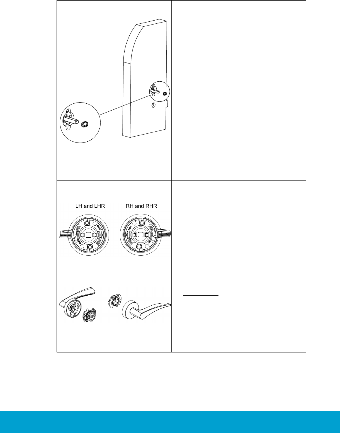
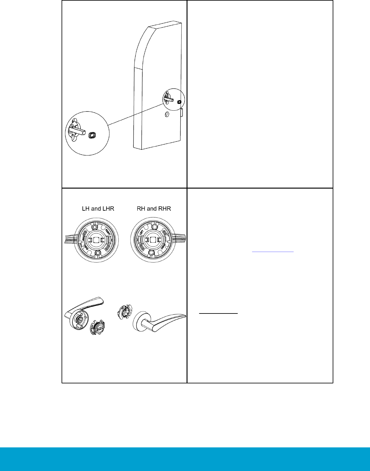
6. Thread the spindle locking clip (21) onto
the spindle handle female Signature (20;
on the inside of the door) by squeezing
hard on the spindle locking clip. Make
sure that the clip clicks onto the hole
in the spindle handle.
Figure 29
Figure 30
7. At delivery, the handle retainers*
Signature (3 and 18) are not mounted
into the handle on inside rose Signature
(2) and handle on outside rose Signature
(17), and they must be prepared
according to the door handing. If the
handle on inside rose Signature is a
left handle (i.e. pointing to the left),
the white retainer should be mounted
on the inside handle. If the handle on
inside rose Signature is a right handle,
the black retainer should be mounted
on the inside handle.
Important: For both left handles
and right handles, make sure that
the handle retainer*Signature is in
the "click" position within the groove
on the shank of the handle.

29
ASSA ABLOY Hospitality 66 1000 023-2
Figure 31
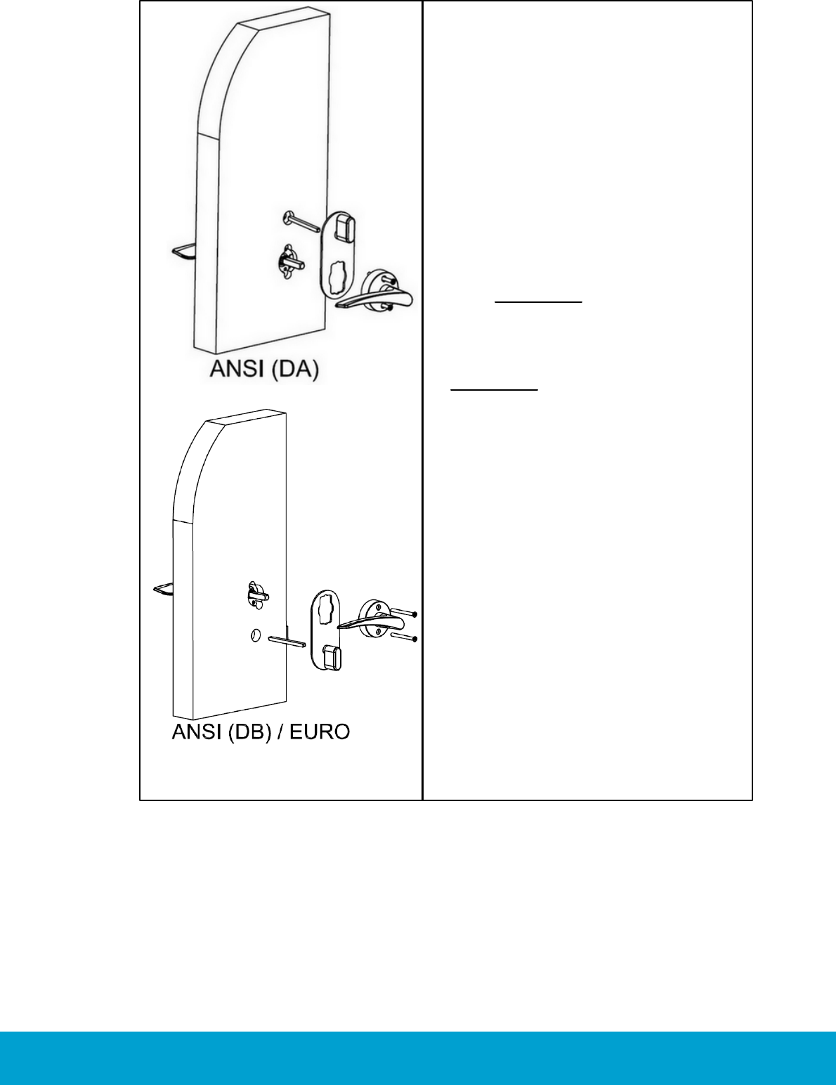
8. Insert the thumbturn spindle Signature
(9) into the lock case from the inside.
The marked end on the spindle handle
must be inserted into the thumb turn
knob. Important: For ANSI (DB) and
EURO, the thumb turn knob should be
pointing downwards. Insert the inside
handle onto the spindle handle and
screw the handles together.
Important: For ANSI (DA), the thumb
turn knob should be pointing upwards.
Insert the inside handle onto the spindle
handle and screw the handles together.
9. Insert the inside handle including the
handle retainer*Signature (3) onto
the spindle handle. Fasten the handles
together using screws Signature M5 (1).
30
ASSA ABLOY Hospitality 66 1000 023-2
Figure 32
Figure 33
Figure 34
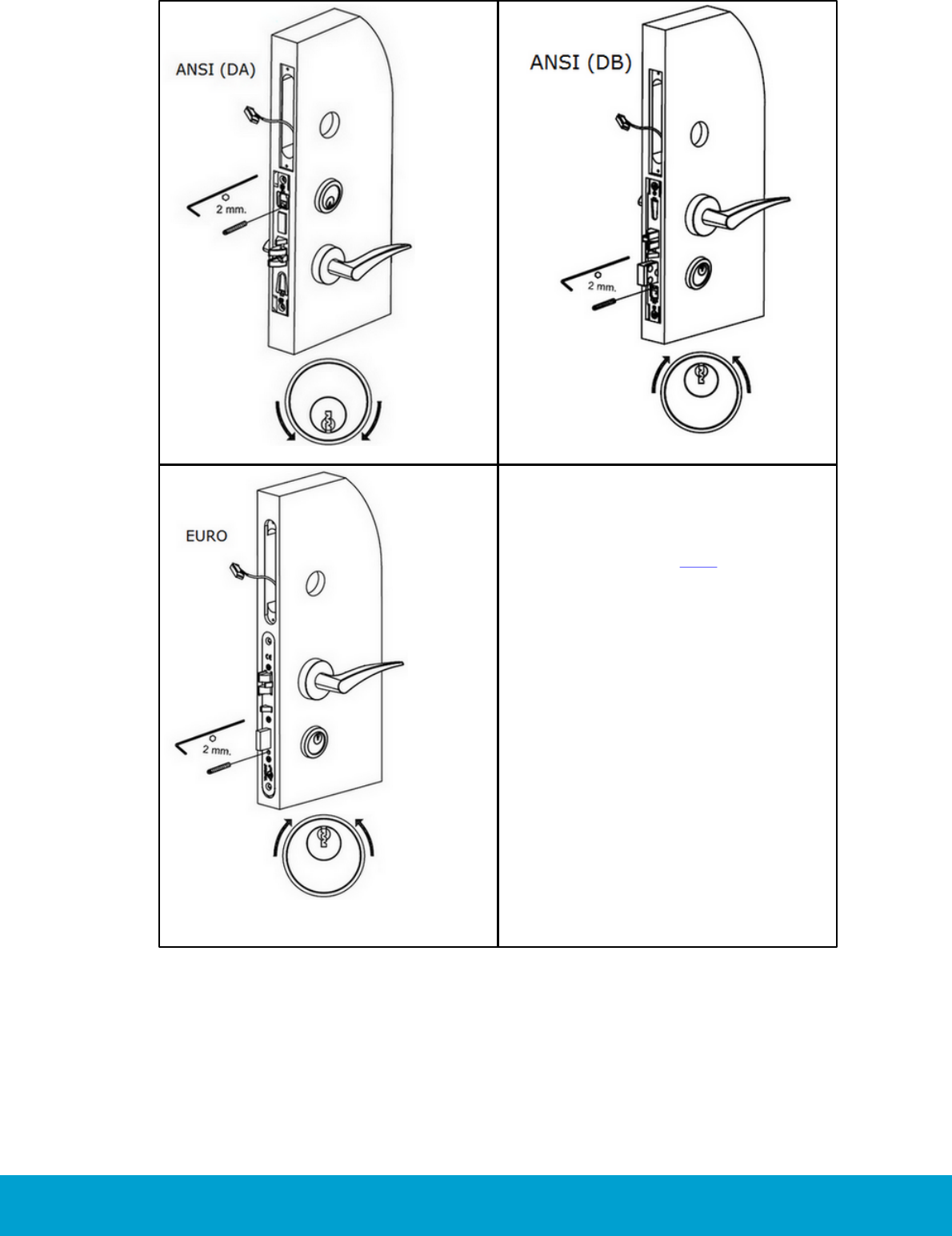
10. If cylinder is used:
- Thread the spring cylinder rose
Signature (14) onto the cylinder
(15; see full names of the
cylinder variants here) from
the cylinder-arm side.
- Insert the cylinder into the
cylinder rose.
- Use a key and screw the cylinder
into the lock case.
- Tighten the cylinder until the
cylinder rose is tight to the door.
- Fix the cylinder into the lock case.
- The keyhole should always point
towards the handle.
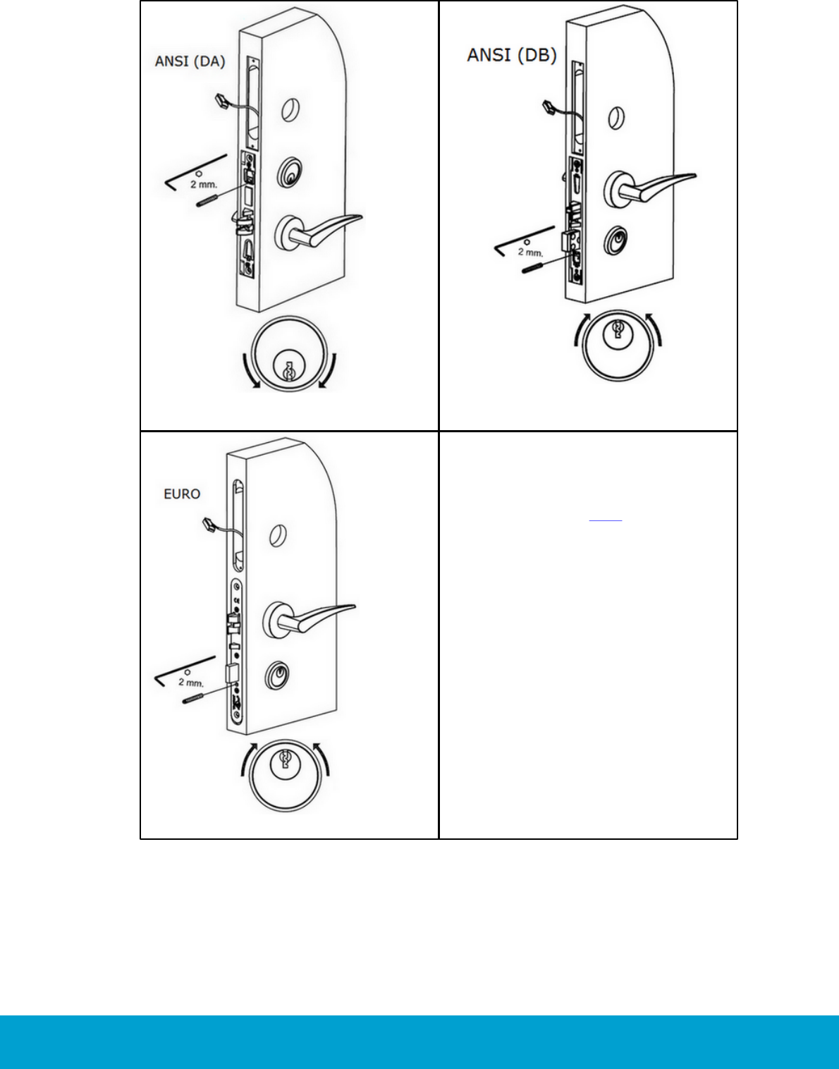
11. There are two ways for installing
the cylinder fastening screw:
- The nomal way; insert the
2 mm Unbrako into the screw,
and insert the screw in the hole
facing towards the lock front.
Tighten the cylinder in the
lock case as illustrated in
Figures 32-34.
31
ASSA ABLOY Hospitality 66 1000 023-2
Figure 35
- A more secure way; fix the cylinder in
place by using the fixing-screw tool kit.
Use the L-shaped Allen key to lock the
headless fixing screw (cylinder screw
is turned upside down) to the T-shaped
tool as illustrated in Figure 35. Using the
T-tool, screw the fixing screw in place as
shown earlier to fix the cylinder in place.
Make sure that the cylinder fixing screw
is tightened in the cylinder. Release the
T-tool from the fixing screw by holding
the T-tool rigid while turning the Allen
key counter-clockwise until the Allen key
is released from the screw; then unscrew
the T-tool.
12. After installation of the cylinder, fix for
ANSI (DA) and ANSI (DB) the face plate
to the lock case after installation of
the cylinder.
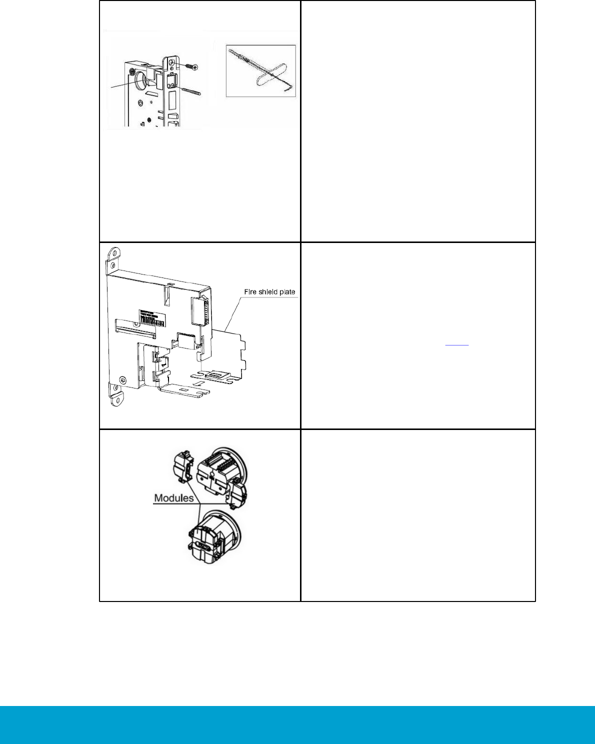
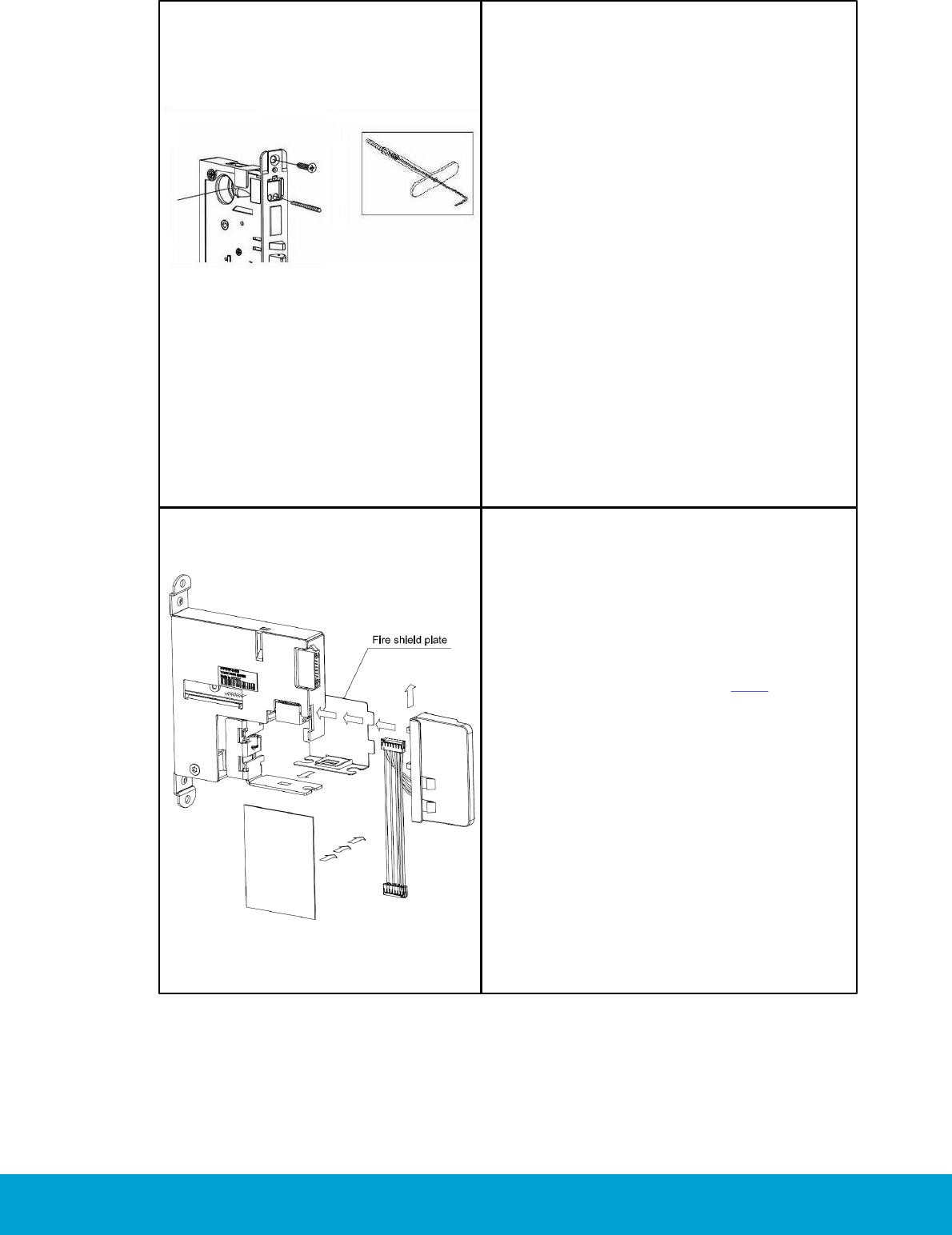
Figure 36
13. Assemble the Essence cassette (8)
before installation.
14. Depending on whether the handing is
left or right (see details here), the fire
shield plate shall be attached on the
opposite side of the LCU (the drawing
shows right handing).
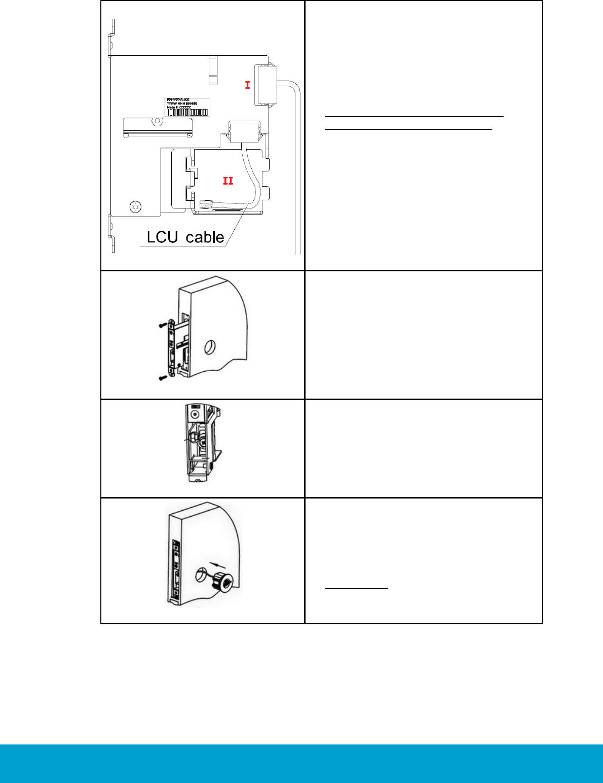
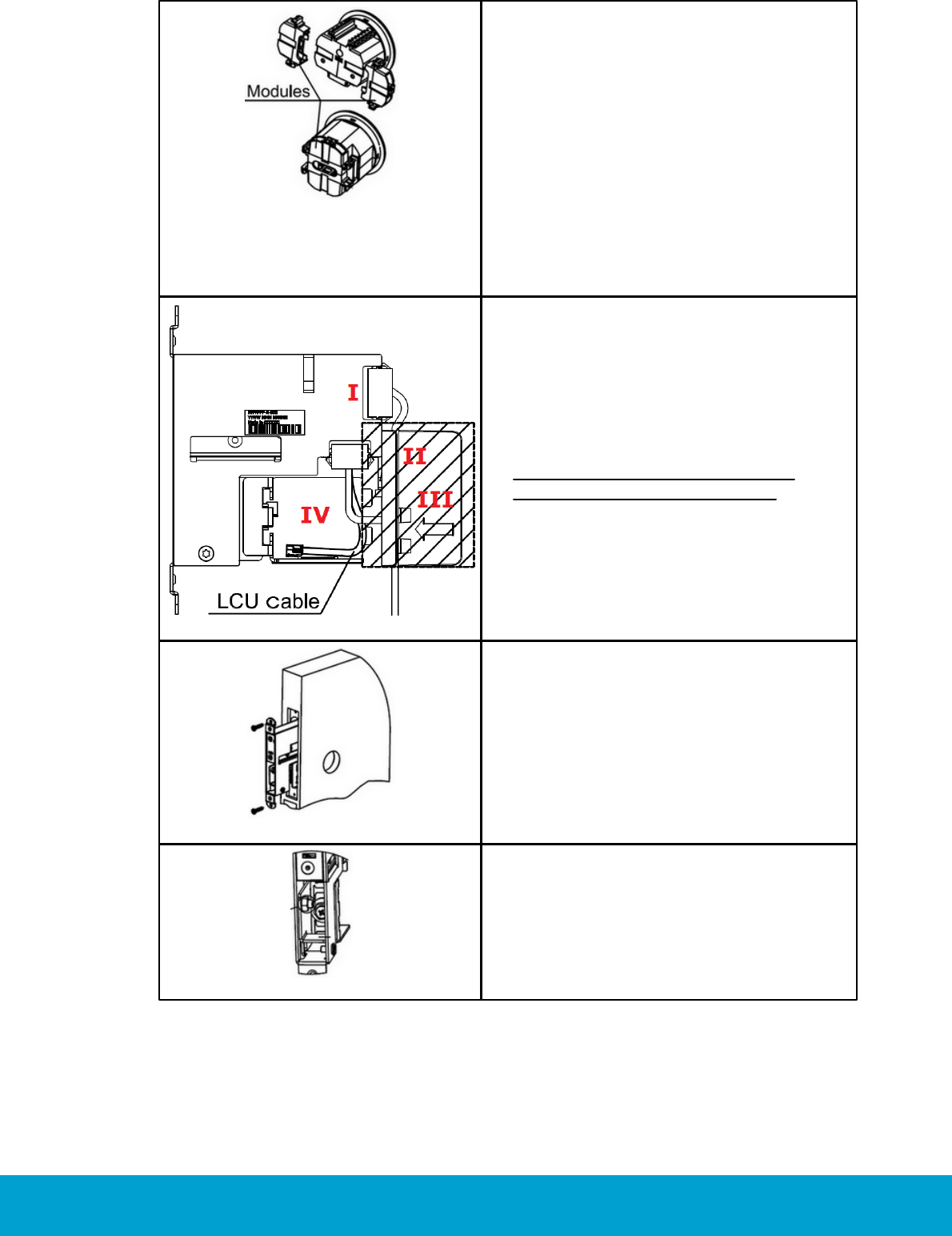
Figure 37
15.To match the B-measurement of the
door leaf, it is possible to increase the
length of the LCU in order to reach the
sprocket*) inside the Essence cassette.
This can be done by adding spacers
(expansion modules), which consist
of two halfs sliding into the slot on the
back of the LCU. The two halfs will meet
and by a “snap-lock” functionality lock
onto the LCU. Additional spacers can
be added on top of the other spacers.
*) The sprocket is only partly locking the LCU in
place after installation.
32
ASSA ABLOY Hospitality 66 1000 023-2
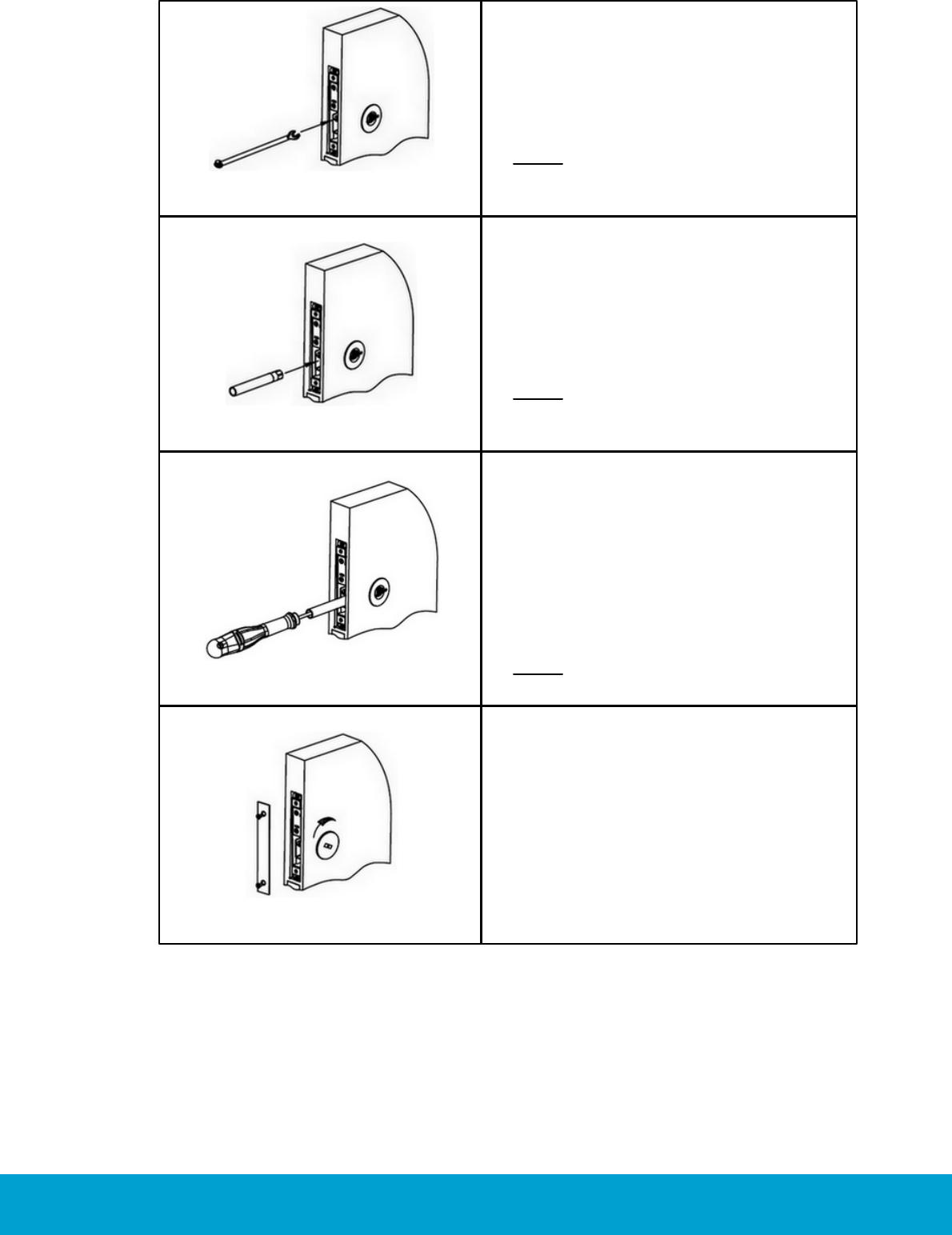
Figure 38
16.Connect the lock case cable to the
Essence cassette (I in Figure 38).
Important before mounting the
Essence cassette in the door:
Make sure that the LCU cable is well
positioned in the space marked with
II in Figure 38, to avoid pinching of
the cable.
Figure 39
17.Insert the Essence cassette into
the door.
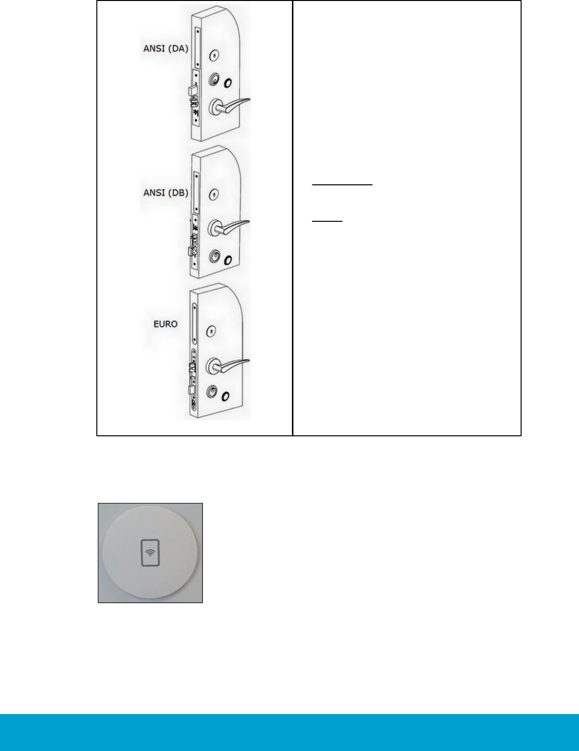
Figure 40
18.Loose the bracket with a wrench (8 mm)
until it moves freely.
Figure 41
19.Connect the LCU cable to the LCU and
adjust the bracket in order to enter the
LCU against the sprocket.
Important: Arrange the cables to
prevent pinching them.
33
ASSA ABLOY Hospitality 66 1000 023-2
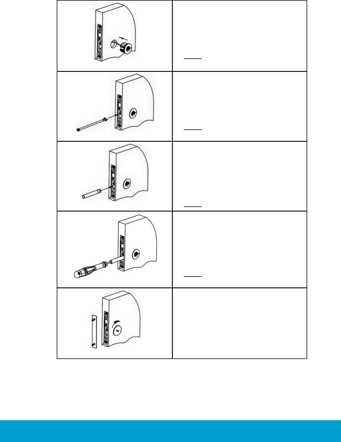
Figure 42
20.Fasten the bracket with the
wrench (8 mm).
Note: Tighten gently.
Figure 43
21.When the LCU has entered the bracket,
use the hexagon pipe to turn the
sprocket in order to pull the LCU
in place.
Note: Tighten gently.
Figure 44
22.When the LCU is pulled all the way
into the door leaf, fasten the screw
in the centre of the sprocket by using
a Pozidriv 2 screwdriver.
Note: Tighten gently.
Figure 45
23.Insert 3 AA batteries.
24.Fix the face plate of the case, upload
the firmware and attach the service cover
of the LCU. The service cover shall be
inserted 90 degrees to the left and then
be turned 90 degrees clockwise in order
to fasten.

34
ASSA ABLOY Hospitality 66 1000 023-2
Figure 46
25. To install the strike: The depth
in the frame must be sufficient
(min 25,4 mm/1'') for throwing
the deadbolt.
35
ASSA ABLOY Hospitality 66 1000 023-2
Figure 47
26. Make a full test of the lock.
Important: Do not close the door
before the lock has been tested.
Note: If cylinder with cap is used,
the installation of the cap should
be the last operation in the mounting
of the lock.
4.5.1 To access the service jack
Figure 48
When access to the service jack is needed, twist by hand
the service cover counterclockwise and lift it off. To mount
it again, twist it clockwise until the RFID card symbol looks
as in Figure 48.

36
ASSA ABLOY Hospitality 66 1000 023-2
5. To check the installation
A quick check of the installation and operation is important in order to
discover any problems related to the installation or the lock itself.
5.1 Checklist for installation and cut-out
5.1.1 Lock mortise
The lock front/face plate should be flush with the door edge.
5.1.2 Cylinder
The cylinder should be flush with the cylinder rose and properly fixed.
5.1.3 Roses/door handles
All should be aligned vertically, horizontally and firmly tightened. Make sure there
are no gaps between the door surface and the lock installation.
5.1.4 Striker plate
The depth in the frame must be sufficient for throwing the deadbolt with small
clearance (min. clearance 26.4 mm; 1.04") and releasing the latch (min. clearance
20 mm; 0.79").

37
ASSA ABLOY Hospitality 66 1000 023-2
5.2 Operational check
5.2.1 Outside and inside handle
Handles must return to a horizontal position after being depressed and slowly
released. The handle on outside rose Signature (see pos 17 in the exploded views
of section 4.3) can only be depressed when the lock is in an unlocked position.
5.2.2 Latch
The latch must release freely into the striker plate. When the latch is released
into the striker plate there should be minimal door movement.
5.2.3 Thumbturn
The escutcheon thumbturn Signature (pos 4 in the exploded views of section 4.3)
must throw and retract the deadbolt freely, also when thrown into the striker plate.
5.2.4 Cylinder
When using an emergency key (mechanical), the latch and the deadbolt must
throw and retract freely.
5.2.5 Latch, auxiliary latch and deadbolt
When the deadbolt has been retracted by the escutcheon thumbturn Signature
(pos 4 in the exploded views of section 4.3) - or the handle on inside rose Signature
(pos 2 in the exploded views of section 4.3) - and the handle on inside rose Signature
is fully depressed, the latch, auxiliary latch and deadbolt should be flush with the
lock front.

38
ASSA ABLOY Hospitality 66 1000 023-2
5.3 Security function check
5.3.1 Auxiliary latch function
When depressing the auxiliary latch, the latch should be blocked. Make sure the
latch is not snagged by the striker plate when the door is closed. According to
the ANSI standard, the latch shall be blocked when depressing the auxiliary latch
0-9.5 mm (0-0.37") measured from lock front. For EURO locks, the requirement
is 0-3 mm (0-0.118"); the actual dimension is typically 0-6 mm (0-0.236").
5.3.2 Panic release function
When the door is closed and the deadbolt is thrown, depress the inside handle.
The deadbolt and the latch must be retracted.
5.4 Electronic check
Always check that the electronics works before closing the door.
To check the privacy function you need to have a card without deadbolt override,
use a staff card issued when the Visionline system setup has been performed.
If the deadbolt is thrown, you should get three very short yellow flashes.
The outside door handle should still be blocked. If the deadbolt is not thrown,
you should get a green light. The outside door handle can easily be depressed.

39
ASSA ABLOY Hospitality 66 1000 023-2
6. Maintenance
For a reliable operation of the lock, a certain level of maintenance is required.
6.1 Lubrication
All parts that need lubrication are already lubricated by ASSA ABLOY Hospitality.
No parts should therefore need any further lubrication.
Caution: The use of lubricants containing solvents or graphite will void the warranty
on the lock.
6.2 Loose screws and functional test
Check for loose screws, especially the door handle fastening screws, at scheduled
times. Also, perform a functional test (see chapter 5) at scheduled times; at least
once per year is recommended.
6.3 To replace the batteries
The LCU 5350 (pos 11 in the exploded views of section 4.3) checks the battery
voltage when a staff card is used. The check is performed when the lock motor is
activated. If the battery voltage is below the acceptable, the LCU 5350 signals with
four short yellow flashes. The door will still unlock as long as the battery voltage is
high enough to operate the lock motor; this gives a green flash. If there is no green
flash at the end, the battery voltage is below next critical level and will not operate
the lock motor.
Important: Battery check and/or replacement should be performed at
scheduled intervals.
Important: It is recommended to always make a read-out of the time in the lock
after a battery exchange to make sure that it is correct. Use a service cable and a
service PC with the software Lock Service 3G; see Quick reference guide Lock Service
3G for details. If the time is not correct, a soft reset has occurred; see details on how
to proceed in step 9 below.
To replace the batteries:
1. Important: Make sure to have fresh batteries ready since the battery holder
4.5V with new batteries must be connected as quickly as possible after the
old batteries have been disconnected, else a soft reset may take place.
Do not present any card during the battery exchange. If other batteries than
those provided by ASSA ABLOY Hospitality are used, make sure that they

40
ASSA ABLOY Hospitality 66 1000 023-2
are alkaline or long life batteries.
2. Remove the front end by loosening the two screws.
3. Drag out the battery holder 4.5V.
4. Exchange the batteries in the battery holder 4.5V with fresh ones.
Important: The old batteries should be treated in accordance with local
regulations regarding recycling.
5. Reinstall the battery holder 4.5V.
Important: If a short green flash is seen when the battery is connected,
a soft reset has been done since the lock has been without power too long.
Be observant on the green flash; it can be hard to see due to surrounding light.
See in step 9 below how to proceed if a soft reset has taken place.
6. Mount the front end with the two screws.
7. Make a read-out of the time in the lock with Lock Service 3G to make sure
that the time is correct. If it is not, use Lock Service 3G to set the time. If stand
open and/or privacy are applicable, these parameters must by set in the lock
again; if the Online option is applicable in Visionline, they are sent online,
but not instantly. These parameters can also be set with a stand open card
and privacy card respectively; see User manual Visionline for details.
6.4 To troubleshoot the mechanical operation
If a lock does not work properly when a card is used, you must determine whether
the malfunction is due to a card error or to a mechanical error. Many mechanical
malfunctions can be detected by a visual inspection. If a lock cannot be operated
when a card is used – even though the reader displays a green LED – or if the lock
is difficult to operate, check the items stated in the following sections.
6.4.1 Latch retraction
Depress the latch with your thumb. If it does not depress easily, either the lock case
is in binding lock case components are malfunctioning. Remove the lock case from
the door and depress the latch. If the latch depresses easily when the lock case is
removed from the door, reinstall the lock case carefully testing at each stage of
assembly. After installation of a lock, check for full extension of the latch. If the
latch does not extend completely, binding between the lock case and the mortise
pocket or other lock parts may be interfering with operation.
6.4.2 Handle return
If the handle on outside rose Signature (pos 17 in the exploded views of section 4.3)
does not return to a horizontal position after the door has been operated, the handle
return spring (which is located inside the handle on outside rose Signature) may
be broken or displaced. Remove the door handle roses to check the handle
return spring.

41
ASSA ABLOY Hospitality 66 1000 023-2
If the handle on inside rose Signature (pos 2 in the exploded views of section 4.3) sags,
door alignment may be causing binding. In this case, loosen the door handle screws and
depress the handle. If the handle returns freely with the screws Signature M5 (pos 1 in
the exploded views of section 4.3) loosened, align the lock so that the handle continues
to return after the screws are tightened. The handle may also sag because the hub
spring, in the lock case, is broken or weak.
6.4.3 Lock operation
If it is difficult to depress the handles, loosen the door handle screws and try again.
If the lock is still difficult to operate, loosen the lock case screws. This procedure may
help detect binding. Sometimes binding is caused by improperly drilled holes for the
door handle screws. Be careful if enlarging the screw holes to reduce the binding.
The door handle roses may not cover enlarged screw holes, and the enlarged holes
could cause recurring alignment problems.
6.4.4 Thumbturn
The escutcheon thumbturn Signature (pos 4 in the exploded views of section 4.3)
should extend and retract the deadbolt easily. Difficulty in turning usually results from
poor striker plate alignment. Operate the escutcheon thumbturn Signature with the door
open. If the escutcheon thumbturn Signature operates easily with the door open but is
difficult to operate with the door closed, the striker plate is not well aligned. Reduce or
add door silencing pads to avoid re-positioning the striker plate. Sometimes filing the
striker plate slightly can alleviate striker plate binding. Adjusting the striker plate may
be a good solution.
Loosening the door handle screws and re-tightening may correct the alignment.
However, escutcheon thumbturn Signature difficulty can indicate more serious lock
case malfunction. If the deadbolt is difficult to operate, even when the lock case is
removed from the door, replace the lock case.
6.4.5 Auxiliary latch
Press and hold the auxiliary latch and then try to press the latch. You should not be
able to depress the latch bolt when the auxiliary latch is engaged. If the auxiliary bolt
never disengages (the latch bolt cannot be retracted), check for binding. If the mortise
pocket is not wide enough, the auxiliary latch cannot move correctly.
6.5 To power open the lock
It is possible to power open the LCU 5350 (pos 11 in the exploded views of section
4.3) with a service cable and a service PC with the Lock Service 3G software; see
Quick reference guide Lock Service 3G for detailed information.

42
ASSA ABLOY Hospitality 66 1000 023-2
6.6 Lock repair and part replacement
6.6.1 To replace the lock case
In order to replace the lock case, refer to the Installation section, but do everything
in the reverse order. Everything except the striker plate must be removed from
the door.
Tip: Use a long set of pliers to remove the spindle locking clip.
6.6.2 To replace an LCU Essence RFID assy (3G) or LCA
To replace an LCU Essence RFID assy (3G) or LCA, see the Installation section.
43
ASSA ABLOY Hospitality 66 1000 023-2
Appendix A: Part dimensions table for
Signature/Essence
Figure A1
44
ASSA ABLOY Hospitality 66 1000 023-2
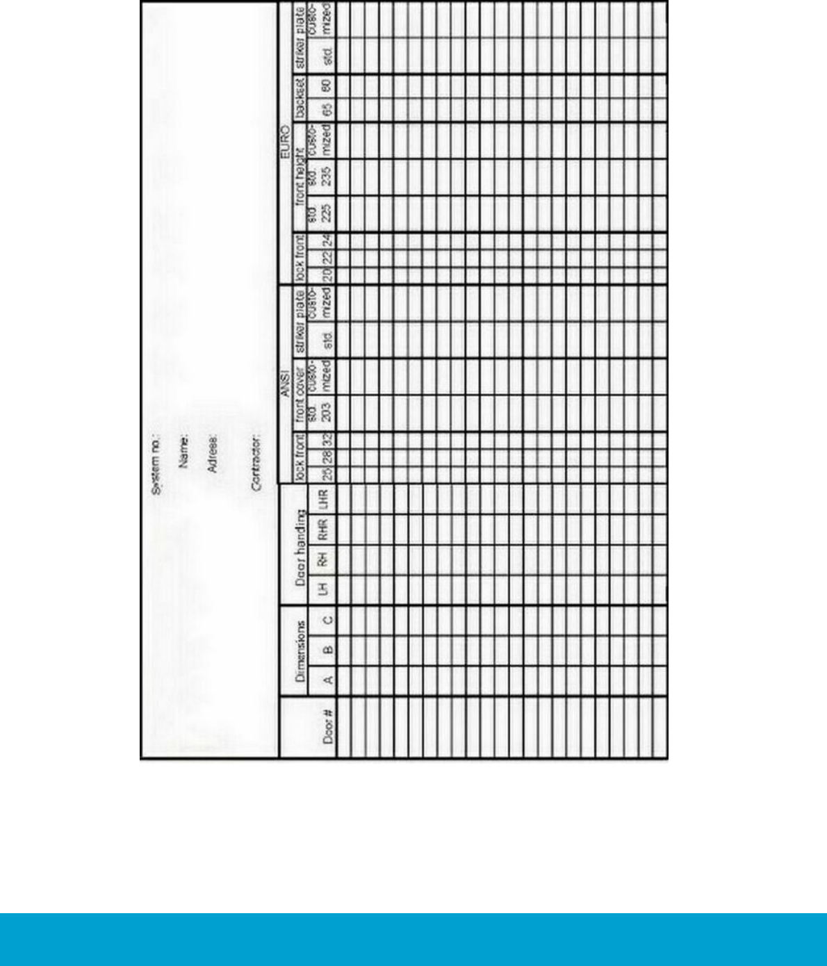
Appendix B: Site survey form
Figure B1
45
ASSA ABLOY Hospitality 66 1000 023-2
Appendix C: To install ADB
This appendix contains drawings needed for an installation or upgrade of
ANSI (DA) ADB, striker plate
ANSI (DA) ADB, mortise
ANSI (DB) ADB, striker plate
ANSI (DB) ADB, mortise
EURO ADB lock case
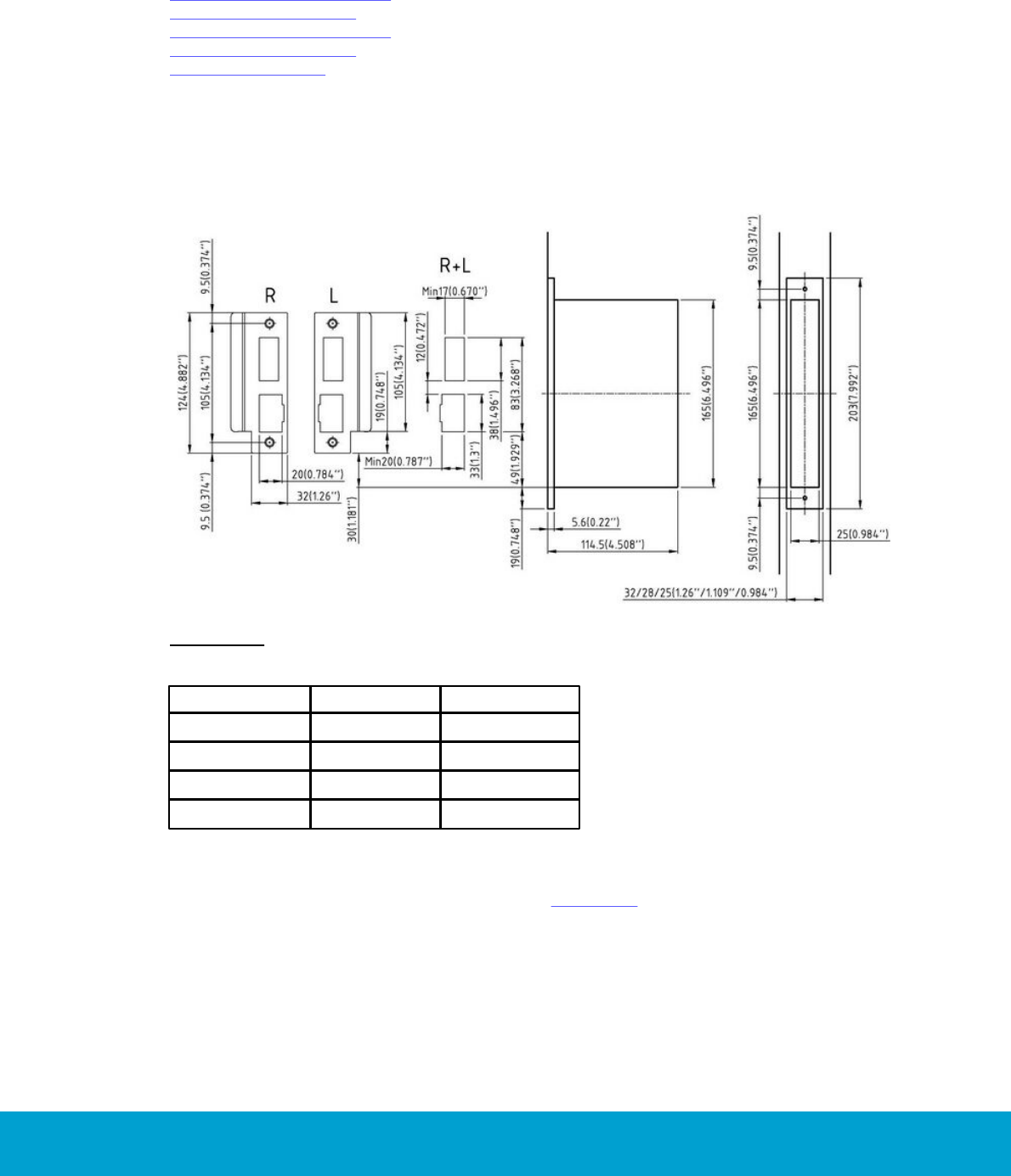
ANSI (DA) ADB, striker plate
When installing or upgrade to ANSI DA ADB lock case, the external striker plate must be
installed as shown in Figure C1; dimensions in mm (inches).
Figure C1: Striker plate and cut-out
Important: When installing an ADB lock case, the ADB striker plate with
curved lip must always be used (hands of door L and R).
Door handing
Striker plate L
Striker plate R
LH (Rx)
X
RHR (Ro)
X
RH (Lx)
X
LHR (Lo)
X
Table C1: Striker plates for different door handings
All frames (wooden and steel frames)
1. Install the lock in the door according to the Installation section.
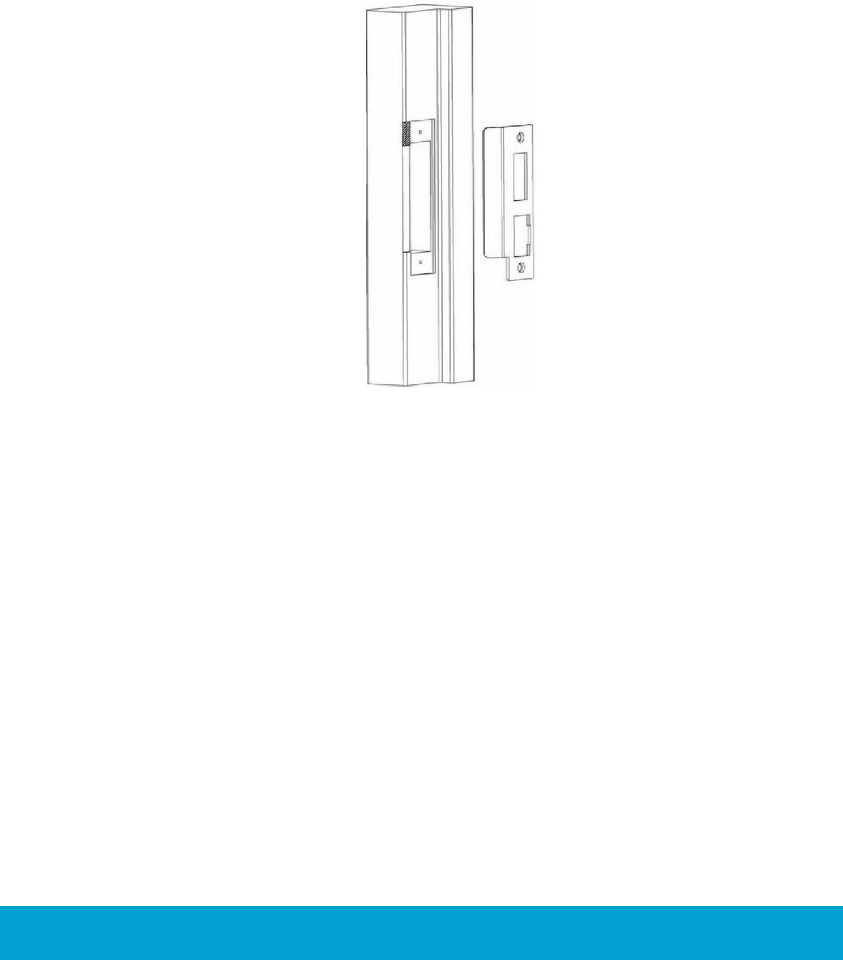
2. Place the ADB striker plate in the frame as shown in Figure C1, 49 mm
(1 30/32") above the bottom of the lock front (30mm + 19mm, i.e. 3/4"+1 3/16").
46
ASSA ABLOY Hospitality 66 1000 023-2
Appendix C: To install ADB
ANSI (DA) ADB, mortise
If the frame is mortised for a standard ANSI striker plate, the frame must be modified
as shown in Figure C2.
Figure C2: Remove the
hatched area
47
ASSA ABLOY Hospitality 66 1000 023-2
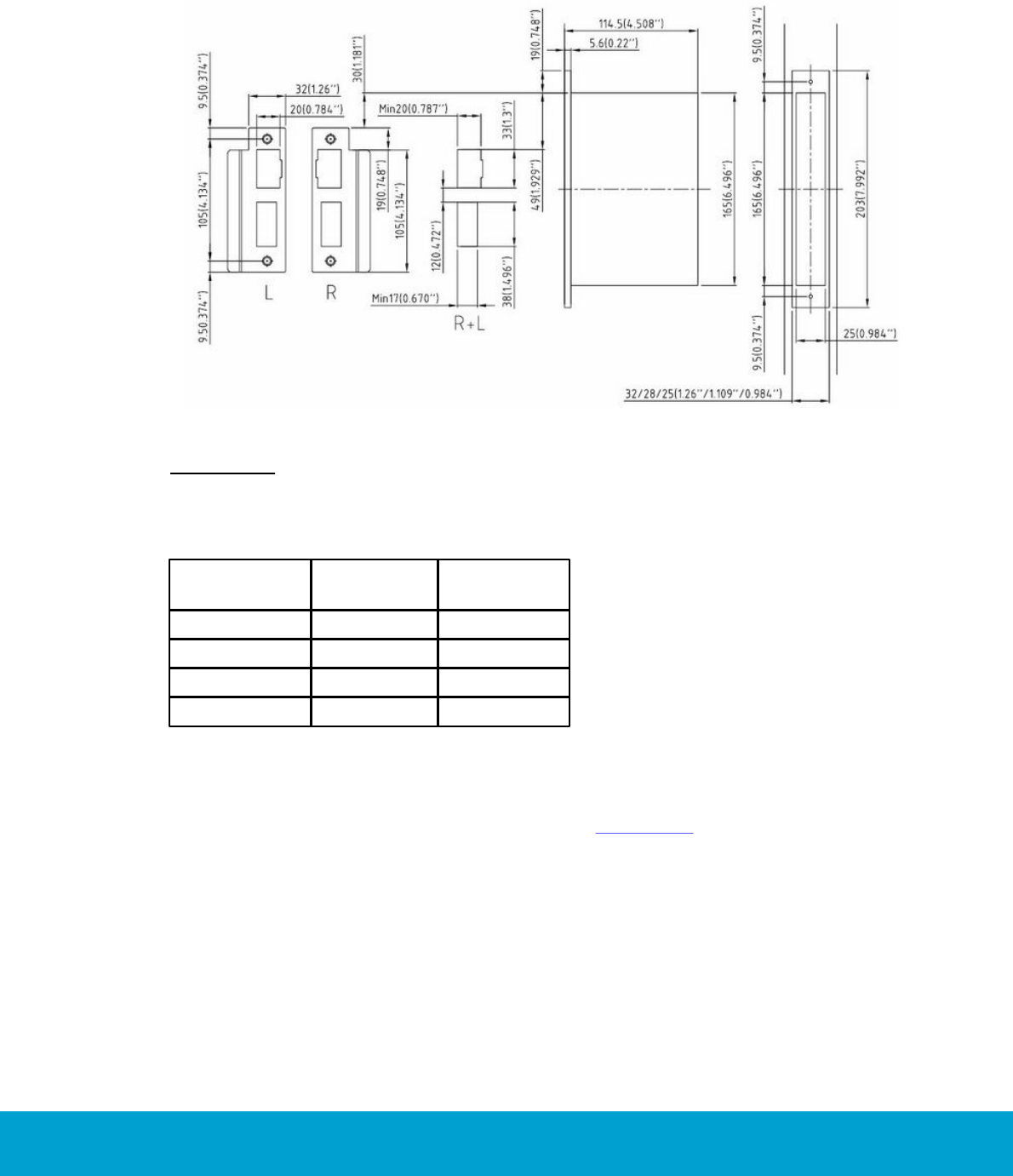
ANSI (DB) ADB, striker plate
When installing or upgrade to ANSI DB ADB lock case, the external striker plate must
be installed as shown in Figure C3; dimensions in mm (inches).
Figure C3: Striker plate and cut-out
Important: When installing an ADB lock case, the ADB striker plate with curved lip
must always be used (hands of door L and R).
Door handing
Striker plate
L
Striker plate
R
LH (Rx)
X
RHR (Ro)
X
RH (Lx)
X
LHR (Lo)
X
Table C2: Striker plates for different door handings
All frames (wooden and steel frames)
1. Install the lock in the door according to the Installation section.
2. Place the ADB striker plate in the frame as shown in Figure C3, 49 mm
(1 30/32") below the top of the lock front (30mm + 19mm, i.e. 3/4"+1 3/16").
48
ASSA ABLOY Hospitality 66 1000 023-2
Appendix C: To install ADB
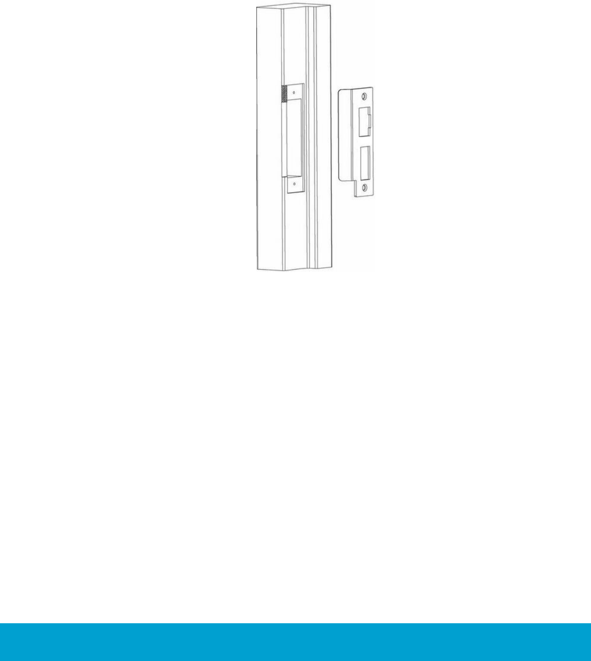
ANSI (DB) ADB, mortise
If the frame is mortised for a standard ANSI striker plate, the frame must be modified
as shown in Figure C4.
Figure C4: Remove the
hatched area
49
ASSA ABLOY Hospitality 66 1000 023-2
Appendix C: To install ADB
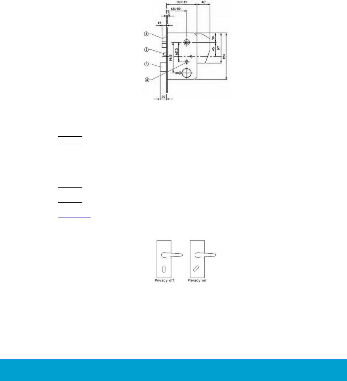
ADB lock case, EURO
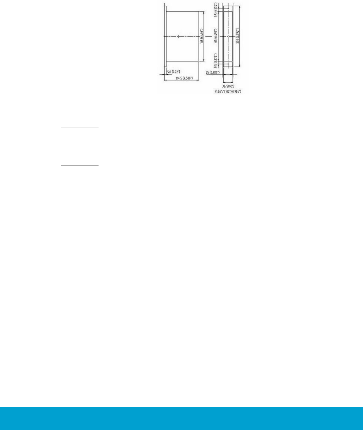
When installing or upgrade to EURO lock case, the external striker plate must be
installed as shown in Figure C5; dimensions in mm.
Figure C5: EURO ADB lock case
The notes below refer to Figure C5.
Note 1: Latch - same function as standard ASSA ABLOY Hospitality EURO lock.
Note 2: Auxiliary latch/deadbolt trigger - when the door is closed and the auxiliary
latch hits the striker plate/frame, the automatic deadbolt will be thrown and the latch
will be blocked. Always install a striker plate before installing the lock case in the
door. If the door with lock case is closed without a striker plate, the auxiliary latch
will be jammed in the frame cut-out. The dimension from the front of the lock case
to the striker plate must not exceed 4mm to obtain automatic deadbolt function.
Note 3: Automatic deadbolt - the deadbolt throws automatically when the door
is closed.
Note 4: Privacy hub - with the thumbturn, the privacy hub can be rotated 45°.
When the escutcheon thumbturn Signature (pos 4 in the exploded views of
section 4.3) is pointing downwards, the privacy function is off. When the escutcheon
thumbturn Signature is rotated 45°, the privacy function is on. The deadbolt cannot
be retracted with the thumbturn.
Figure C6: Thumb turn position at
'privacy off’ and ’privacy on'

50
ASSA ABLOY Hospitality 66 1000 023-2
Appendix D: Online
Introduction
This appendix contains information about the online variant of Essence.
For general information about Essence, see earlier in this manual. There is
also an easy 4-page quick reference, covering both online and offline version.
For full online functionality, Essence is used with an ANSI 4-switch lock case.
If full online functionality is not needed, Essence can be used with lock cases
that are not 4-switch.
A battery holder 4.5V with 3AA batteries is used.
Technical specification
Power
4.5V - 3AA batteries
Reader option
RFID
Online type
RF
Lock case options
(all 4.5V)
ANSI (DA) with
2 switches
70 (2 3/4'') 25/28/32 (63/64'' 1 7/64'' 1 17/64'')
ANSI (DA) with ADB
70 (2 3/4'') 25/28/32 (63/64'' 1 7/64'' 1 17/64'')
ANSI (DA) with
4 switches
70 (2 3/4'') 25/28/32 (63/64'' 1 7/64'' 1 17/64'')
ANSI (DB) with
2 switches
70 (2 3/4'') 25/28/32 (63/64'' 1 7/64'' 1 17/64'')
ANSI (DB) with ADB
70 (2 3/4'') 25/28/32 (63/64'' 1 7/64'' 1 17/64'')
ANSI (DB) with
4 switches
70 (2 3/4'') 25/28/32 (63/64'' 1 7/64'' 1 17/64'')
ANSI AUS
70 (2 3/4'') 25/28/32 (63/64'' 1 7/64'' 1 17/64'')
ANSI JPN
70 (2 3/4'') 25/28/32 (63/64'' 1 7/64'' 1 17/64'')
EURO with 2 switches
65/80 20/22/24
EURO with ADB
65 20/22/24
Audit trail
2000 events
Cylinder option
Yes
System compatibility
Visionline
Table D1
51
ASSA ABLOY Hospitality 66 1000 023-2
Appendix D: Online
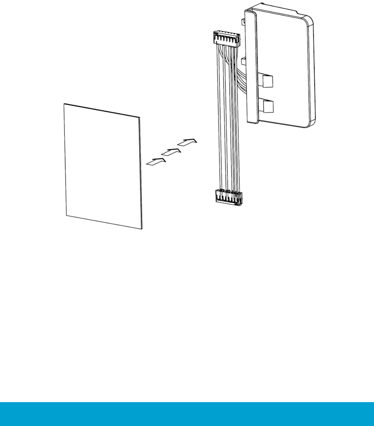
Online kit
Figure D1: The online kit is purchased separately and
contains ZigBee endnode, plastic cover, Y-cable and cooling material.
52
ASSA ABLOY Hospitality 66 1000 023-2
Appendix D: Online
To install an online lock
Note: The position numbers in bold refer to the exploded views in section 4.3.
Figure D2
Figure D3
Figure D4
Note: The position numbers in bold refer
to the exploded views in section 4.3.
1. Position the cables into the door
before inserting the lock case (22).
The connector on the cable must be
bent before being threaded into the
hole through the door. Important:
Do not lubricate the lock case.
2. Position the lock case into the edge of
the door and fasten it with two screws
wood, countersunk 5X25 mm (23).
If applicable, do not forget to install
the cylinder fastening clip before
inserting the lock case.
53
ASSA ABLOY Hospitality 66 1000 023-2
Figure D5
Figure D6
3. Before inserting the spindle handle female Signature (20) and the spindle
handle male Signature (19) into the lock case, check that the spindle threads
are lubricated with grease.
4. Screw the spindle handle female Signature onto the spindle handle male Signature
and then reverse it (3/4 turn).
5. Insert the spindle handles into the lock case from the outside of the door so that
the hole that goes through the spindle handle is visible on the inside (room side)
of the door. Note: The spindle handle marked 'EXT' must be on the outside of
the door.
54
ASSA ABLOY Hospitality 66 1000 023-2
Figure D7
6. Thread the spindle locking clip (21) onto
the spindle handle female Signature (20;
on the inside of the door) by squeezing
hard on the spindle locking clip. Make
sure that the clip clicks onto the hole
in the spindle handle.
Figure D8
Figure D9
7. At delivery, the handle retainers*
Signature (3 and 18) are not mounted
into the handle on inside rose Signature
(2) and handle on outside rose Signature
(17), and they must be prepared
according to the door handing. If the
handle on inside rose Signature is a
left handle (i.e. pointing to the left),
the white retainer should be mounted
on the inside handle. If the handle on
inside rose Signature is a right handle,
the black retainer should be mounted
on the inside handle.
Important: For both left handles
and right handles, make sure that
the handle retainer*Signature is in
the "click" position within the groove
on the shank of the handle.
55
ASSA ABLOY Hospitality 66 1000 023-2
Figure D10
8. Insert the thumbturn spindle Signature
(9) into the lock case from the inside.
The marked end on the spindle handle
must be inserted into the thumb turn
knob. Important: For ANSI (DB) and
EURO, the thumb turn knob should be
pointing downwards. Insert the inside
handle onto the spindle handle and
screw the handles together.
Important: For ANSI (DA), the thumb
turn knob should be pointing upwards.
Insert the inside handle onto the spindle
handle and screw the handles together.
9. Insert the inside handle including the
handle retainer*Signature (3) onto
the spindle handle. Fasten the handles
together using screws Signature M5 (1).
56
ASSA ABLOY Hospitality 66 1000 023-2
Figure D11
Figure D12
Figure D13
10. If cylinder is used:
- Thread the spring cylinder rose
Signature (14) onto the cylinder
(15; see full names of the
cylinder variants here) from
the cylinder-arm side.
- Insert the cylinder into the
cylinder rose.
- Use a key and screw the cylinder
into the lock case.
- Tighten the cylinder until the
cylinder rose is tight to the door.
- Fix the cylinder into the lock case.
- The keyhole should always point
towards the handle.
11.There are two ways for installing
the cylinder fastening screw:
- The nomal way; insert the 2 mm
Unbrako into the screw, and insert
the screw in the hole facing towards
the lock front. Tighten the cylinder in
the lock case as illustrated in Figures
D11-D13.
57
ASSA ABLOY Hospitality 66 1000 023-2
Figure D14
- A more secure way; fix the cylinder in
place by using the fixing-screw tool kit.
Use the L-shaped Allen key to lock the
headless fixing screw (cylinder screw is
turned upside down) to the T-shaped tool
as illustrated in Figure D14. Using the
T-tool, screw the fixing screw in place as
shown earlier to fix the cylinder in place.
Make sure that the cylinder fixing screw
is tightened in the cylinder. Release the
T-tool from the fixing screw by holding
the T-tool rigid while turning the Allen
key counter-clockwise until the Allen
key is released from the screw; then
unscrew the T-tool.
12. After installation of the cylinder, fix for
ANSI (DA) and ANSI (DB) the face plate
to the lock case after installation of
the cylinder.
Figure D15
13. Assemble the Essence cassette (8)
before installation.
14. Depending on whether the handing
is left or right (see details here),
the fire shield plate shall be attached
on the opposite side of the LCU (the
drawing shows right handing).
15. Connect the Y-cable to the endnode
and LCU and also to the 7-pin connector
at the LCA.
16. Snap the plastic cover with ZigBee
endnode inside onto the Essence cassette
until the locking mechanism locks.
17. When the lock case cable has been
connected, fasten the cooling material
on the Essence cassette.
58
ASSA ABLOY Hospitality 66 1000 023-2
Figure D16
18.To match the B-measurement of the
door leaf, it is possible to increase the
length of the LCU in order to reach the
sprocket*) inside the Essence cassette.
This can be done by adding spacers
(expansion modules), which consist
of two halfs sliding into the slot on
the back of the LCU. The two halfs will
meet and by a “snap-lock” functionality
lock onto the LCU. Additional spacers
can be added on top of the other
spacers.
*) The sprocket is only partly locking the LCU in
place after installation.
Figure D17
19.Connect the lock case cable to the
Essence cassette (I in Figure D17).
20.Snap the lock case cable into the cable
gateway in the endnode housing
(II in Figure D17).
21.Fasten the cooling material in the area
marked with III in Figure D17.
Important before mounting the
Essence cassette in the door:
Make sure that the LCU cable is well
positioned in the space marked with
IV in Figure D17, to avoid pinching
of the cable.
Figure D18
22.Insert the Essence cassette into
the door.
Figure D19
23.Loose the bracket with a wrench (8 mm)
until it moves freely.
59
ASSA ABLOY Hospitality 66 1000 023-2
Figure D20
24.Connect the LCU cable to the LCU and
adjust the bracket in order to enter the
LCU against the sprocket.
Note: Arrange the cables to prevent
pinching them.
Figure D21
25.Fasten the bracket with the
wrench (8 mm).
Note: Tighten gently.
Figure D22
26.When the LCU has entered the bracket,
use the hexagon pipe to turn the
sprocket in order to pull the LCU
in place.
Note: Tighten gently.
Figure D23
27.When the LCU is pulled all the way
into the door leaf, fasten the screw
in the centre of the sprocket by using
a Pozidriv #2 screwdriver.
Note: Tighten gently.
Figure D24
28.Insert 3 AA batteries.
29.Fix the face plate of the case, upload
the firmware and attach the service cover
of the LCU. The service cover shall be
inserted 90 degrees to the left and then
be turned 90 degrees clockwise in order
to fasten.
60
ASSA ABLOY Hospitality 66 1000 023-2
Figure D25
30. To install the strike: The depth
in the frame must be sufficient
(min 25,4 mm/1'') for throwing
the deadbolt.
61
ASSA ABLOY Hospitality 66 1000 023-2
Figure D26
31. Make a full test of the lock.
Important: Do not close the door
before the lock has been tested.
Note: If cylinder with cap is used, the
installation of
the cap should be the last operation in
the mounting of the lock.
Battery maintenance
The procedure to replace batteries is the same for online locks as for offline locks;
see section 6.3.

62
ASSA ABLOY Hospitality 66 1000 023-2
Appendix E: Firmware change in LCU 5350
If a lock needs to have its firmware upgraded due to new firmware features etc,
follow the steps below:
1. Choose Upload firmware in the Lock Service 3G software 1).
2. Mark the applicable lock firmware (and if you have touchpad, move the cursor
to be over the Upload button).
3. Connect the service cable to the lock; after a few seconds, the lock LED will
be green. Step 4 below must be performed directly after this 2).
4. Click Upload; a progress bar will show how the upgrade proceeds. When the
upgrade is complete, a message will be shown.
1) Always make sure that the lock firmware which is already included in Lock Service
3G is the latest version. If it is not, see the appendix about firmware upgrade in
Setup manual Visionline for information on how to prepare for lock firmware upgrade,
then choose Download firmware in Lock Service 3G to download the firmware
from the Visionline server to Lock Service 3G. It is also possible to browse to the
firmware file directly from the Upload firmware dialog, but it is recommended
to go via Visionline.
2) If Upload is not clicked within 4 seconds, there will be a timeout and the
service cable must be disconnected and then connected again.

63
ASSA ABLOY Hospitality 66 1000 023-2
Appendix F: Summary of notes
Below is a summary of the important notes etc in this manual. It therefore gives
a condensed overview of what to think of in different phases for the Essence lock,
such as site survey and lock installation. Some tips appear in more than one manual
section; they are then only mentioned once in this appendix. Some tips have been
slightly rewritten to be understandable outside their original context.
1. Introduction
Important: VingCard Essence (v2) can only be installed in non-metallic doors.
2. Site survey
Note: Always make sure to have the correct handing for all doors.
Note: See section 3.1 for an overview of available cut-outs.
Important: The hole for the cylinder is optional and is only to be cut out for locks
equipped with cylinders and only from the outside of the door to the center of the
lock case; i.e., not through the entire door.
Important: If you are going to install the security cylinder Hydra, remember to
make space for the cylinder fastening clip when making the cut-out for the lock case.
Note: Be aware if there is any door gasket.
3. To mortise the door
Important: The lock front can be delivered with a width of 32mm (1.26"), 28mm
(1.102") or 25 mm (0.984"). Make sure that you mortise the door to the correct
dimensions for your lock dimensions. Check the dimensions of the lock before you
start cutting.
Note: Be aware of the dimension 30 mm (1.181'') from the edge of the lock case to
the edge of the striker plate.
Caution: If the cut-out for the deadbolt is less than 25.4 mm (1") deep, the deadbolt
may not be retracted by use of a metal key in case of an emergency when the door is
double locked. (ANSI AUS = 0, ANSI JPN = 21).
Caution: Be aware if there is any door gasket. If so, compensation must be made by
adjusting the horizontal positioning of the striker plate.
Important: If the striker plate is not used (example: steel frame), it is important
that the distance between the latch (lower) cut-out and the deadbolt cut-out must
be 12 mm (0,47") in order for the auxiliary latch to work.

64
ASSA ABLOY Hospitality 66 1000 023-2
4. To install the lock
Note: The online kit and cylinder kit are purchased separately, when applicable.
Important: Do not lubricate the lock case.
Note: If applicable, do not forget to install the cylinder fastening clip before
inserting the lock case.
Note: The spindle handle marked 'EXT' must be on the outside of the door.
Important: For both left handles and right handles, make sure that the handle
retainer*Signature is in the "click" position within the groove on the shank of
the handle.
Important: For ANSI (DB) and EURO, the thumbturn knob should be pointing
downwards. Insert the inside handle onto the spindle and screw the handles together.
Important: For ANSI (DA), the thumbturn knob should be pointing upwards.
Insert the inside handle onto the spindle and screw the handles together.
Important before mounting the Essence cassette in the door:
Make sure that the LCU cable is well positioned in the space marked with II in Figure
38, to avoid pinching of the cable.
Important: Arrange the cables to prevent pinching them.
Note: Tighten gently when fastening the bracket, when turning the sprocket in order
to pull the LCU in place and when fastening the screw in the centre of the sprocket.
Important: Do not close the door before the lock has been tested. This warning is even
more important if the lock is without cylinder.
Note: If cylinder with cap is used, the installation of the cap should be the last operation
in the mounting of the lock.
6. Maintenance
Caution: The use of lubricants containing solvents or graphite will void the warranty
on the lock.
Important: Battery check and/or replacement should be performed at scheduled
intervals.
Important: It is recommended to always make a read-out of the time in the lock after
a battery exchange to make sure that it is correct. Use a service cable and a service PC
with the software Lock Service 3G; see Quick reference guide Lock Service 3G for details.
If the time is not correct, a soft reset has occurred.

65
ASSA ABLOY Hospitality 66 1000 023-2
Important: Make sure to have fresh batteries ready since the battery holder 4.5V
with new batteries must be connected as quickly as possible after the old batteries
have been disconnected, else a soft reset may take place. Do not insert any card during
the battery exchange. If other batteries than those provided by ASSA ABLOY Hospitality
are used, make sure that they are alkaline or long life batteries.
Important: The old batteries shall be treated in accordance with local regulations
regarding recycling.
Important note: If a short green flash is seen when the battery is connected, a soft
reset has been done since the lock has been without power too long. Be observant on
the green flash; it can be hard to see due to surrounding light. If a soft reset has
occurred, the following measures must be taken:
- the time must be reprogrammed into the lock
- if any of the functions stand open (set by card) and/or privacy were used,
they must be set in the lock again.
Tip: Use a long set of pliers to remove the spindle locking clip.
Appendix C: To install ADB
Important: When installing an ADB lock case, the ADB striker plate plate with
curved lip must always be used (hands of door L and R).
Note: Latch - same function as standard ASSA ABLOY Hospitality EURO lock.
Note: Auxiliary latch/deadbolt trigger - when the door is closed and the auxiliary
latch hits the striker plate/frame, the automatic deadbolt will be thrown and the
latch will be blocked. Always install a striker plate before installing the lock case
in the door. If the door with lock case is closed without a striker plate, the auxiliary
latch will be jammed in the frame cut-out. The dimension from the front of the
lock case to the striker plate must not exceed 4mm to obtain automatic
deadbolt function.
Note: Automatic deadbolt - the deadbolt throws automatically when the door
is closed.
Note: Privacy hub - with the thumbturn, the privacy hub can be rotated 45°.
When the escutcheon thumbturn Signature is pointing downwards, the privacy
function is off. When the escutcheon thumbturn Signature is rotated 45°,
the privacy function is on. The deadbolt cannot be retracted with the thumbturn.
Appendix D: Online
See notes for chapter 4: To install the lock.

66
ASSA ABLOY Hospitality 66 1000 023-2
Revision history
Date
Change
By
October 11, 2016
Initial version
KG
Janaury 5, 2017
Added cooling material to online kit
KG

67
ASSA ABLOY Hospitality 66 1000 023-2
E-mail: apac.hospitality@assaabloy.com
ASSA ABLOY Hospitality APAC
Phone: +65 6305 7670
ASSA ABLOY Hospitality EMEA
ASSA ABLOY Hospitality North America
Phone: +47 69 24 50 00
E-mail: emea.hospitality@assaabloy.com
E-mail: lam.hospitality@assaabloy.com
Phone: +1 972 907 2273
ASSA ABLOY Hospitality Latin America
E-mail: northam.hospitality@assaabloy.com
Phone: +52 55 36 40 12 00
www.assaabloyhospitality.com