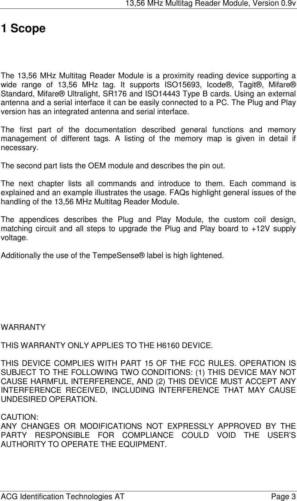
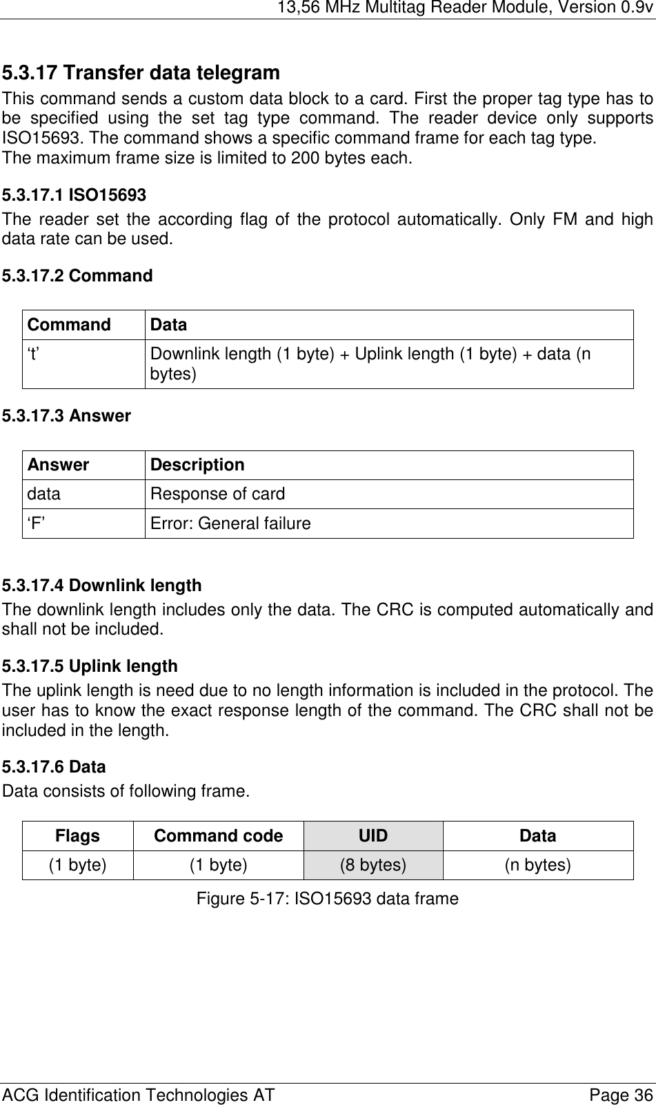
ASSALOY Identification Technologies H102022RFPCHR PCMCIA Compact Flash Card Reader (RF-ID) User Manual Part 1
ASSA ABLOY Identification Technologies GmbH PCMCIA Compact Flash Card Reader (RF-ID) Users Manual Part 1
Contents
- 1. Users Manual Part 1
- 2. Users Manual Part 2
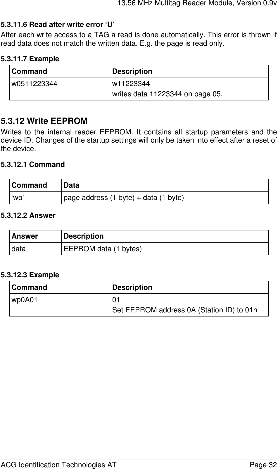
Users Manual Part 1

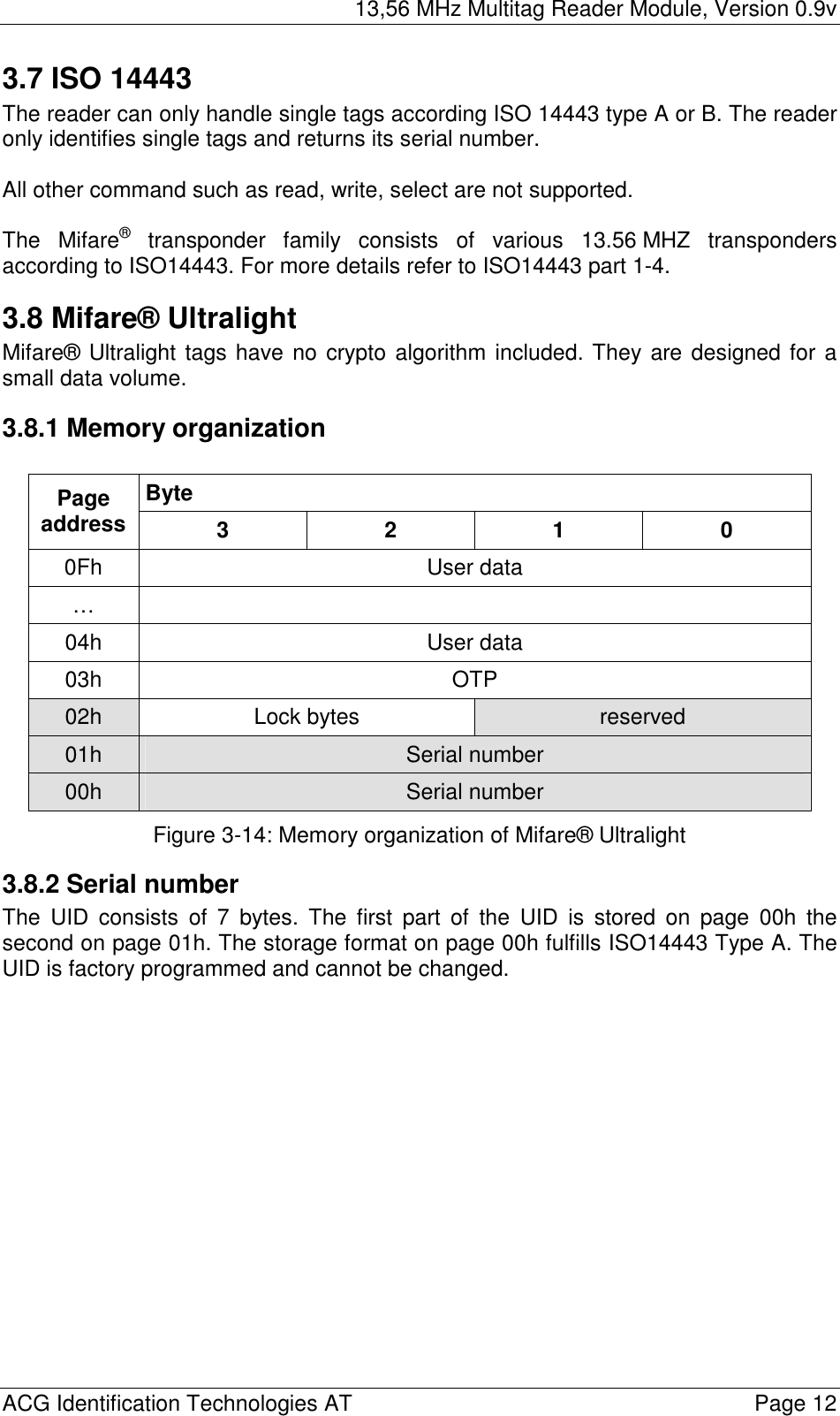
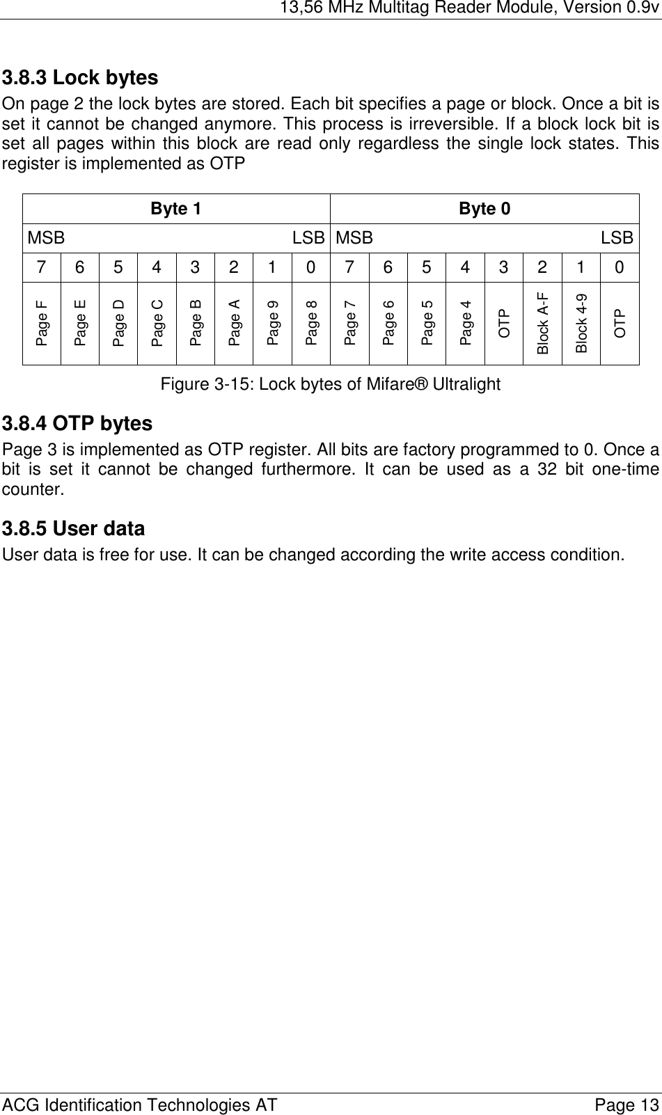
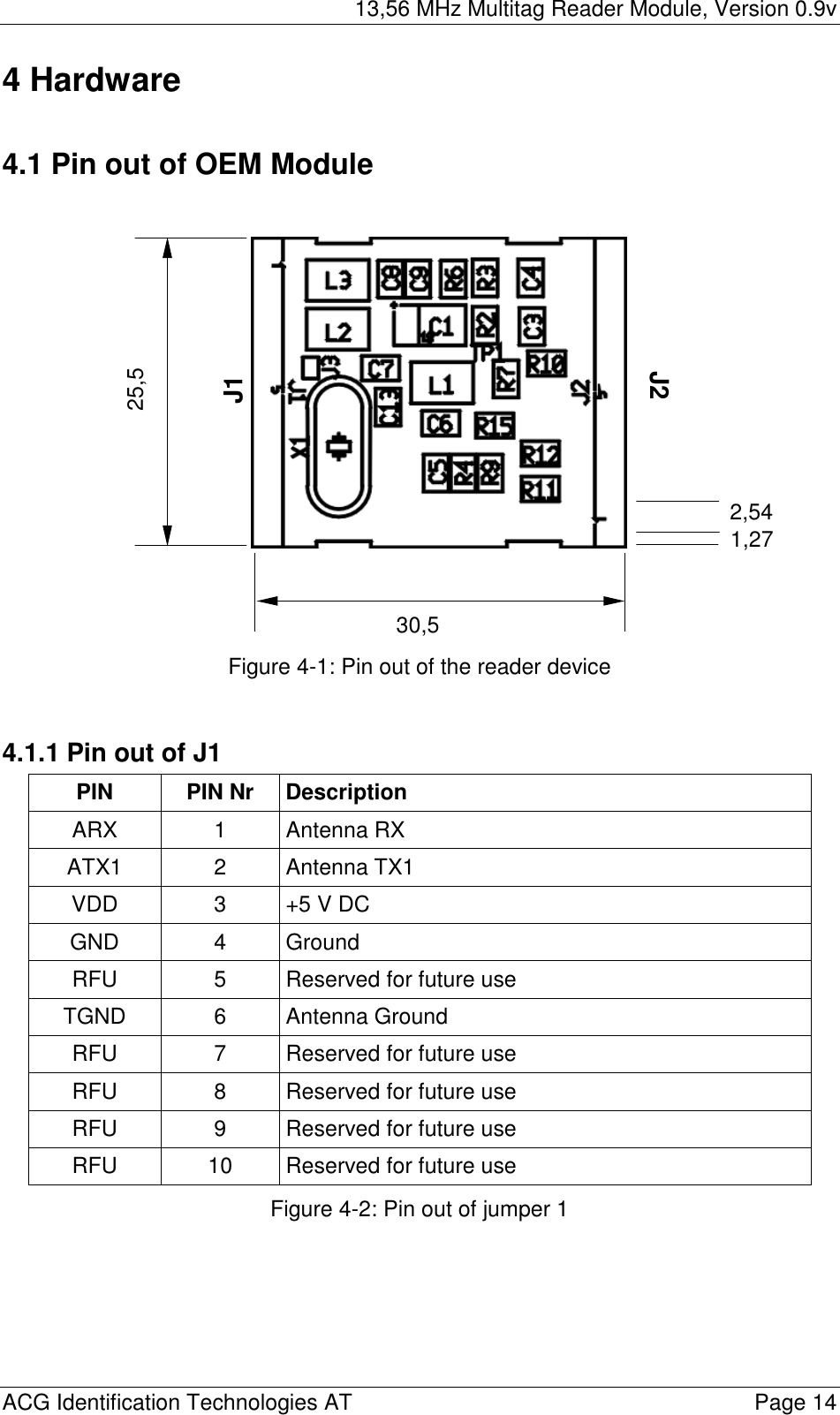
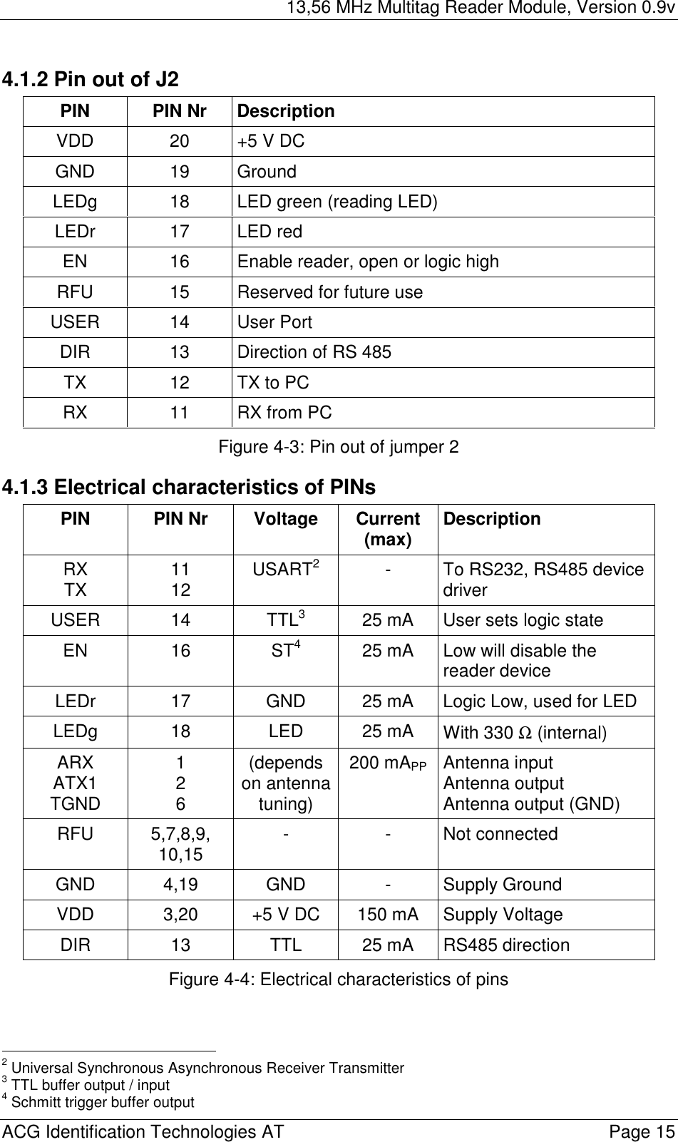
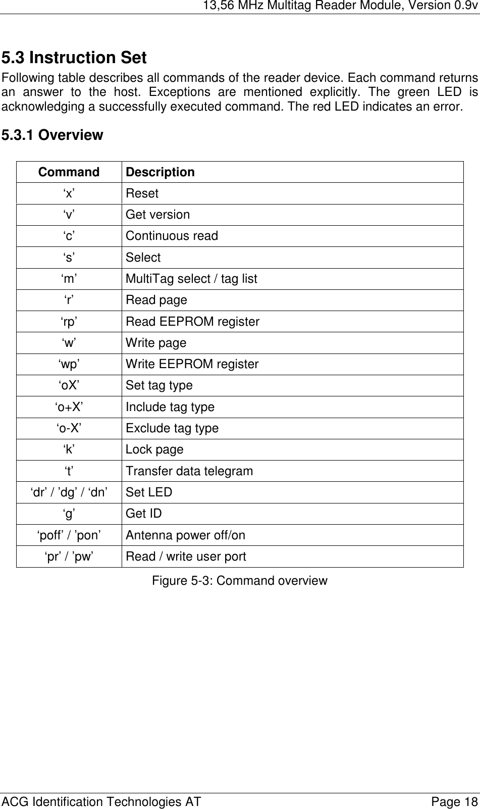
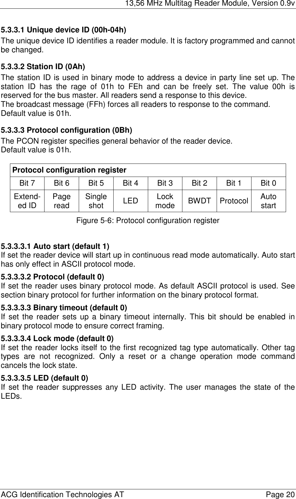
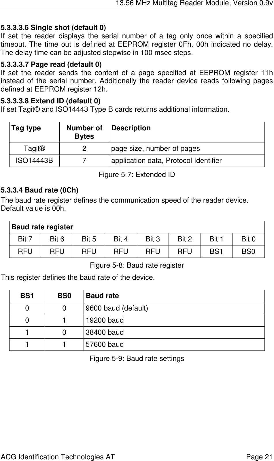
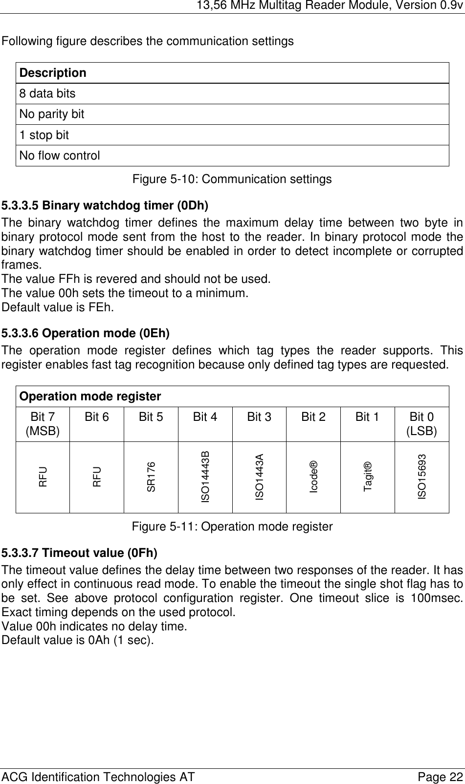
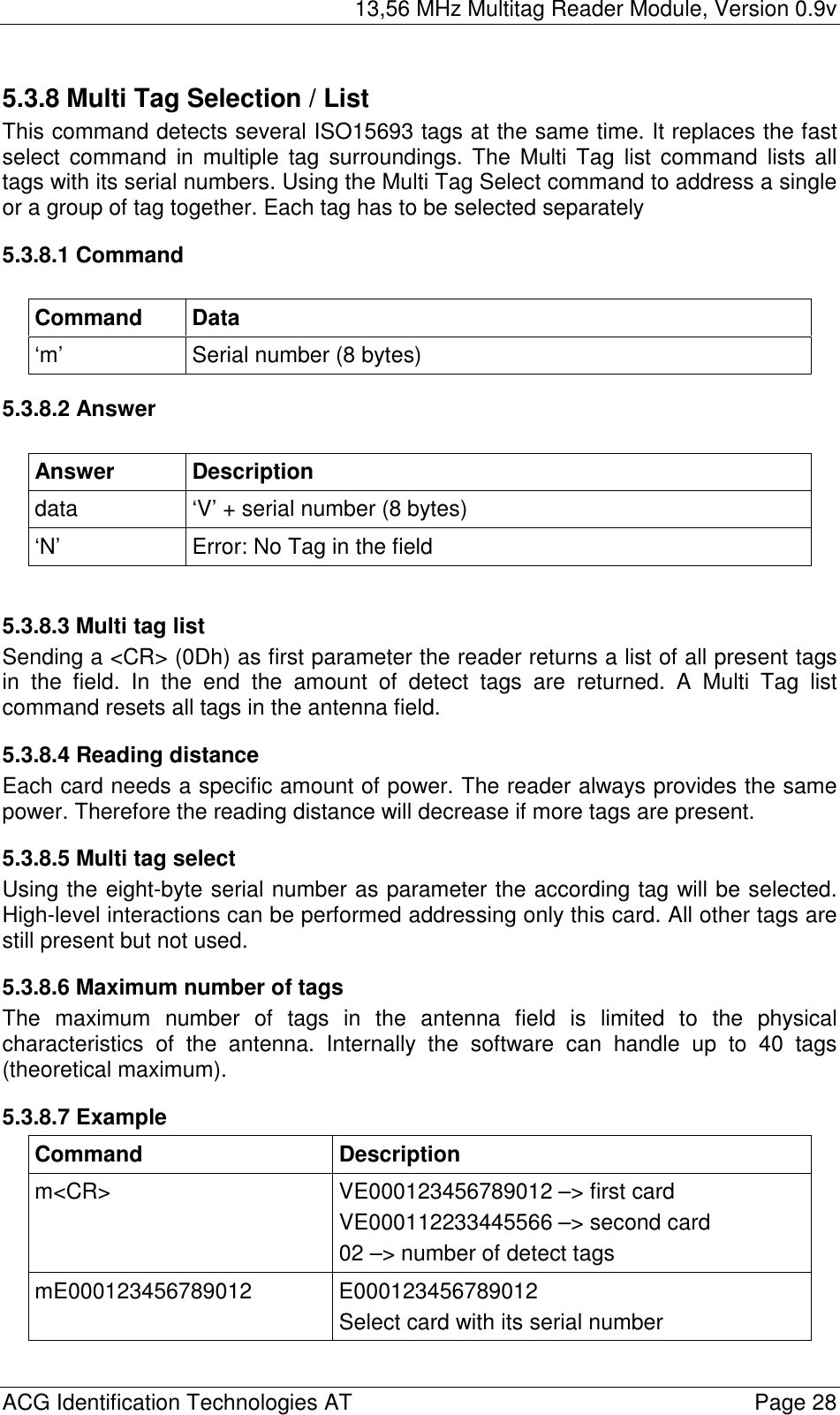
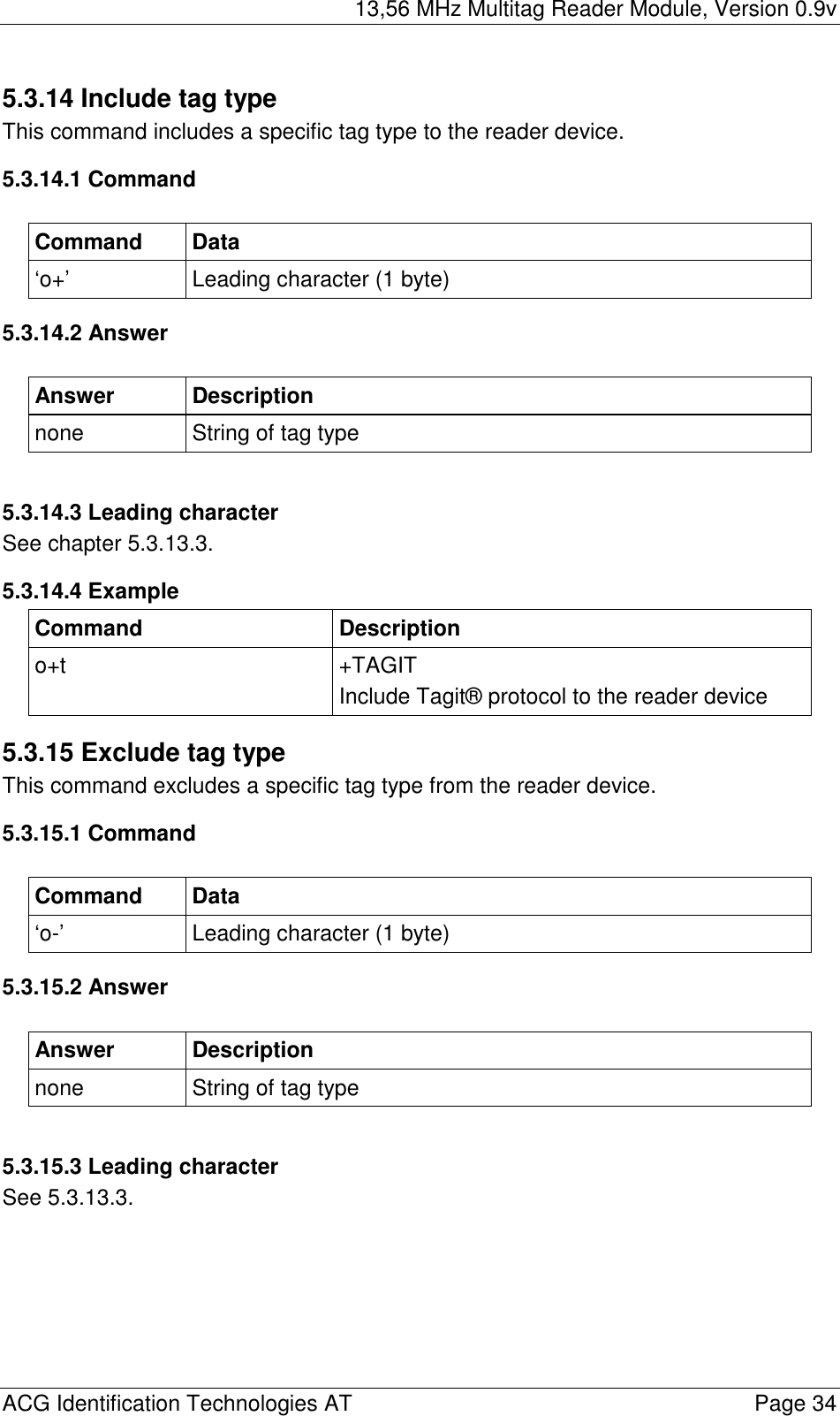
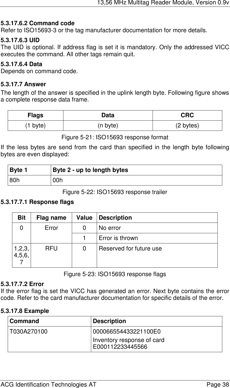
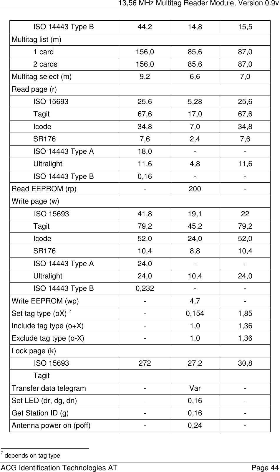
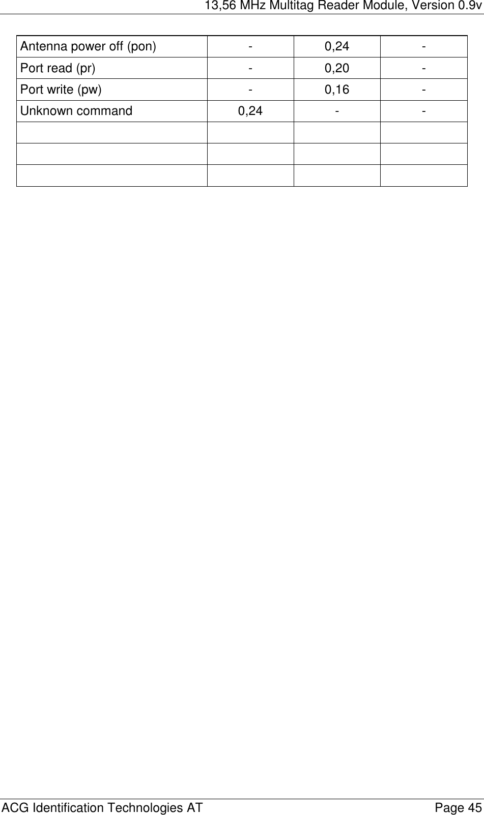
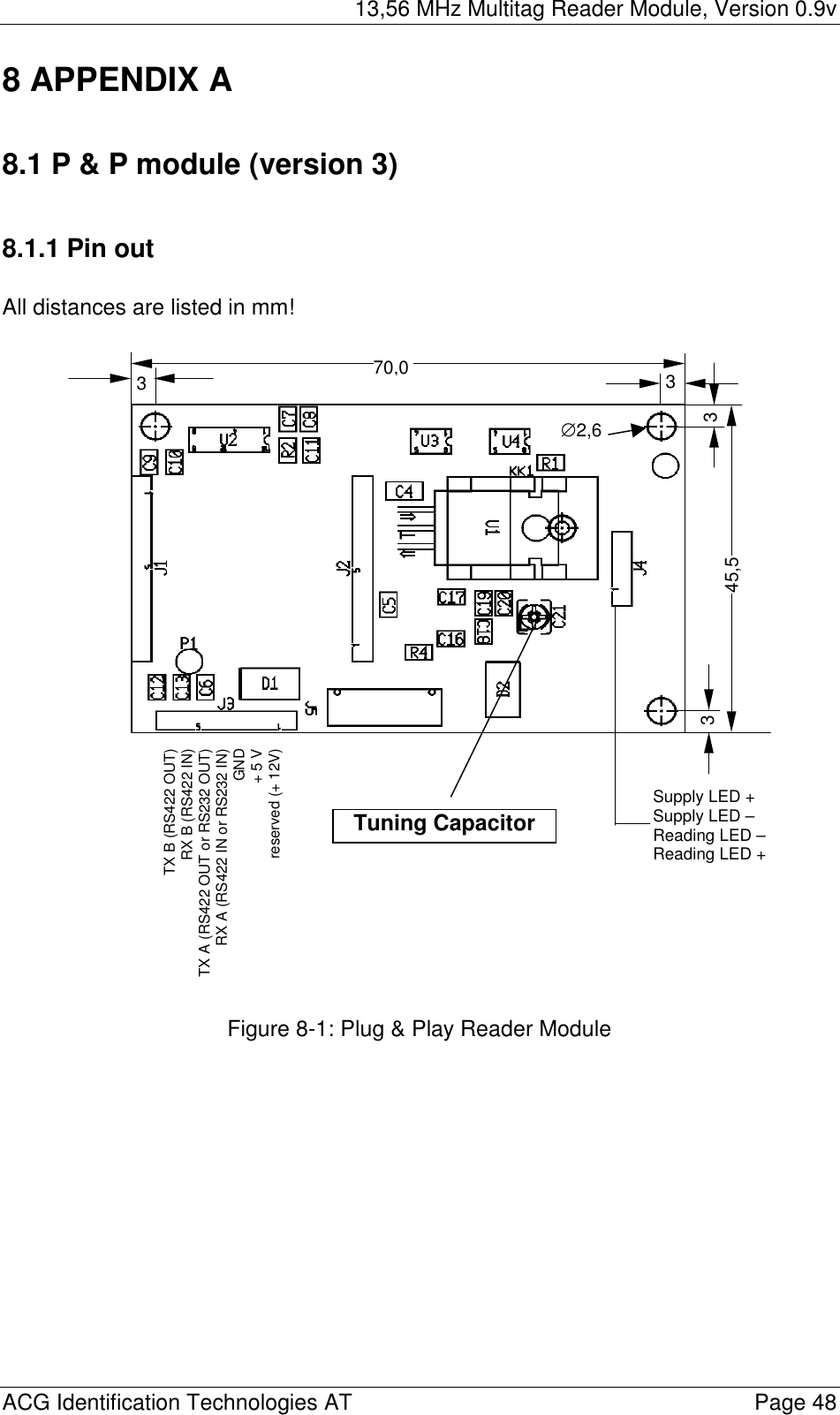
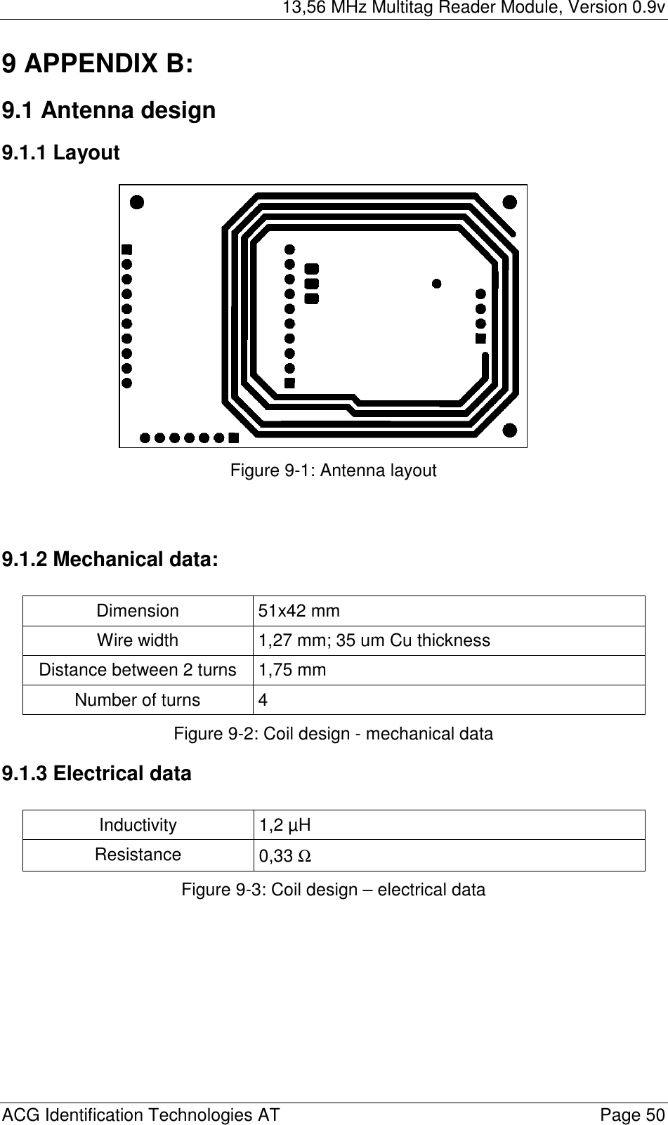
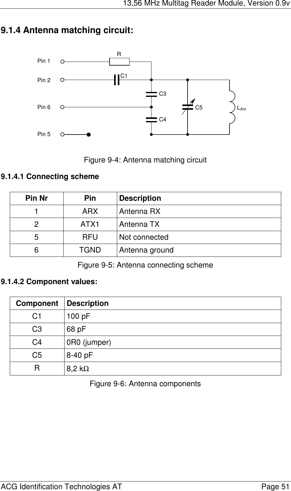
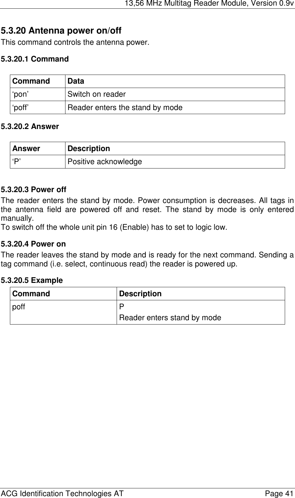
![13,56 MHz Multitag Reader Module, Version 0.9v ACG Identification Technologies AT Page 40 5.3.19.2.1 ASCII mode The station ID has only effect in binary mode. 5.3.19.3 Time slotted answer In party line mode more than one reader can be used simultaneously. The time slotted answer allows a separation of all connected devices. The station ID is used to determine the correct time slot. The reader supports up to 254 unique time slots. Following formula allows calculating the needed time of one time slot. Only one baud rate on the same party line is supported. 6*10][0BaudratesT = Figure 5-25: Time slot formula Following figure shows a timing diagram of time slotted answers. timeslot 0 1 2 3 4 5 252 253 254 T0 T1 T2 T3 T4 T5 T253 T254 T255 HOST ‘g’ → reader (01) ← 01 reader (03) ← 03 reader (04) ← 04 reader (254) ← 254 Figure 5-26: Timing diagram of time slotted answers](https://usermanual.wiki/ASSALOY-Identification-Technologies/H102022RFPCHR.Users-Manual-Part-1/User-Guide-367116-Page-41.png)
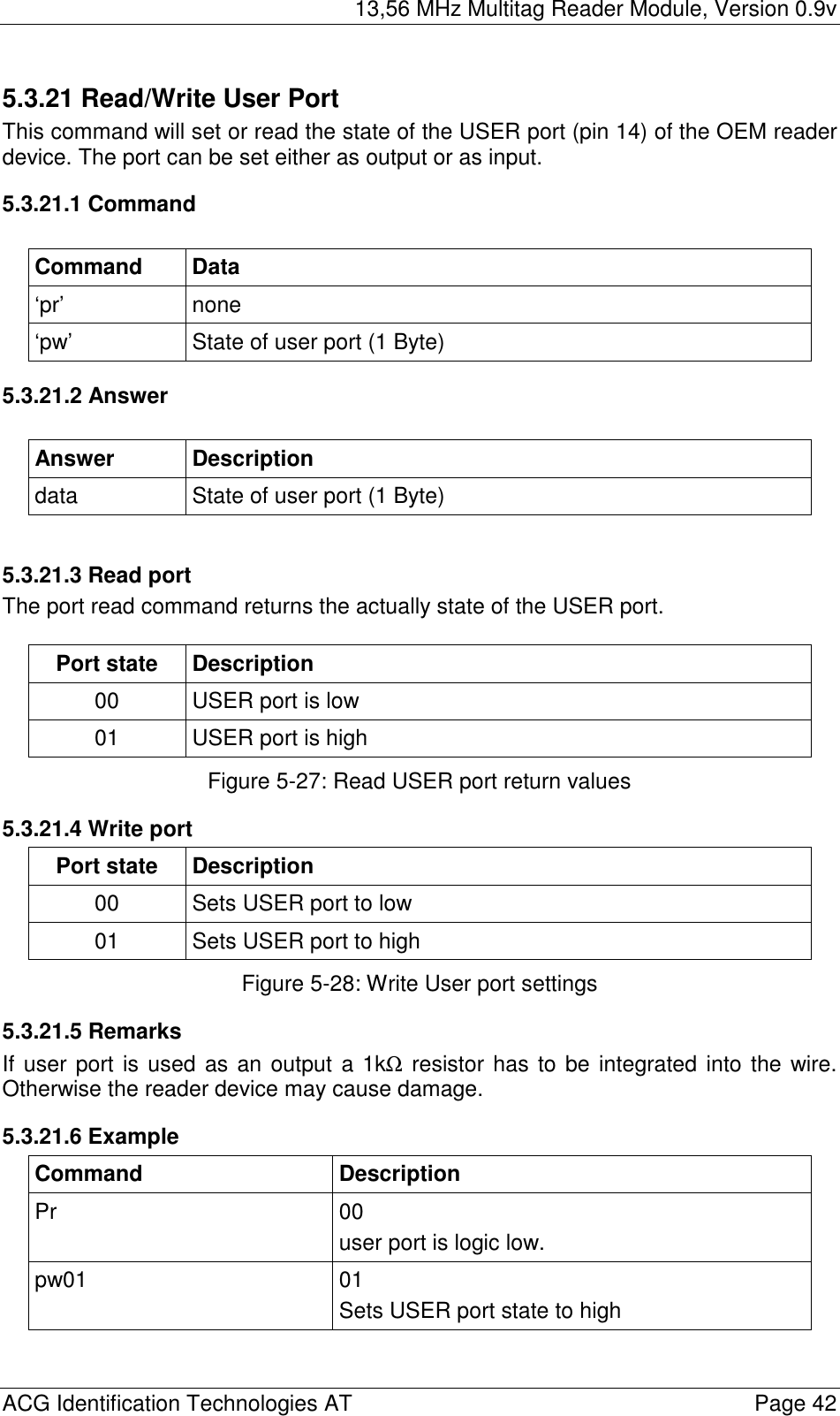
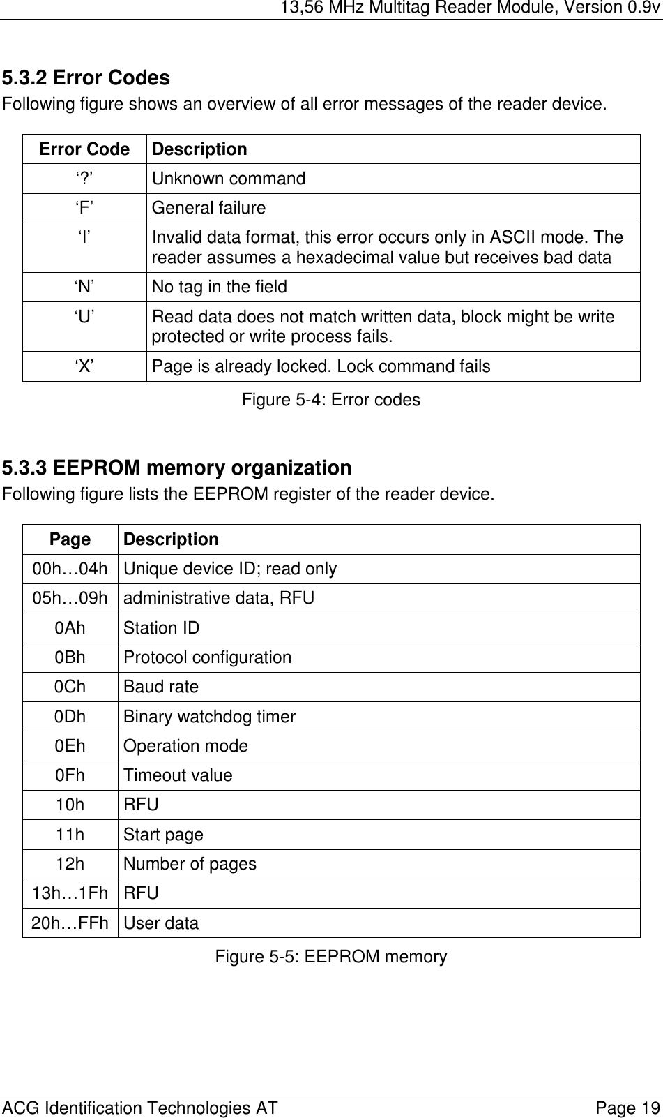
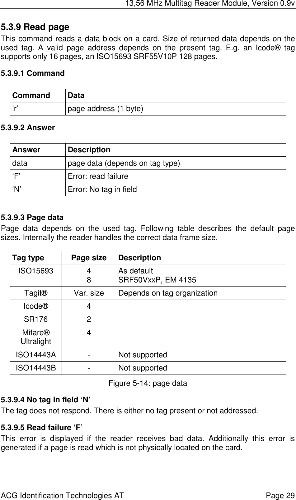
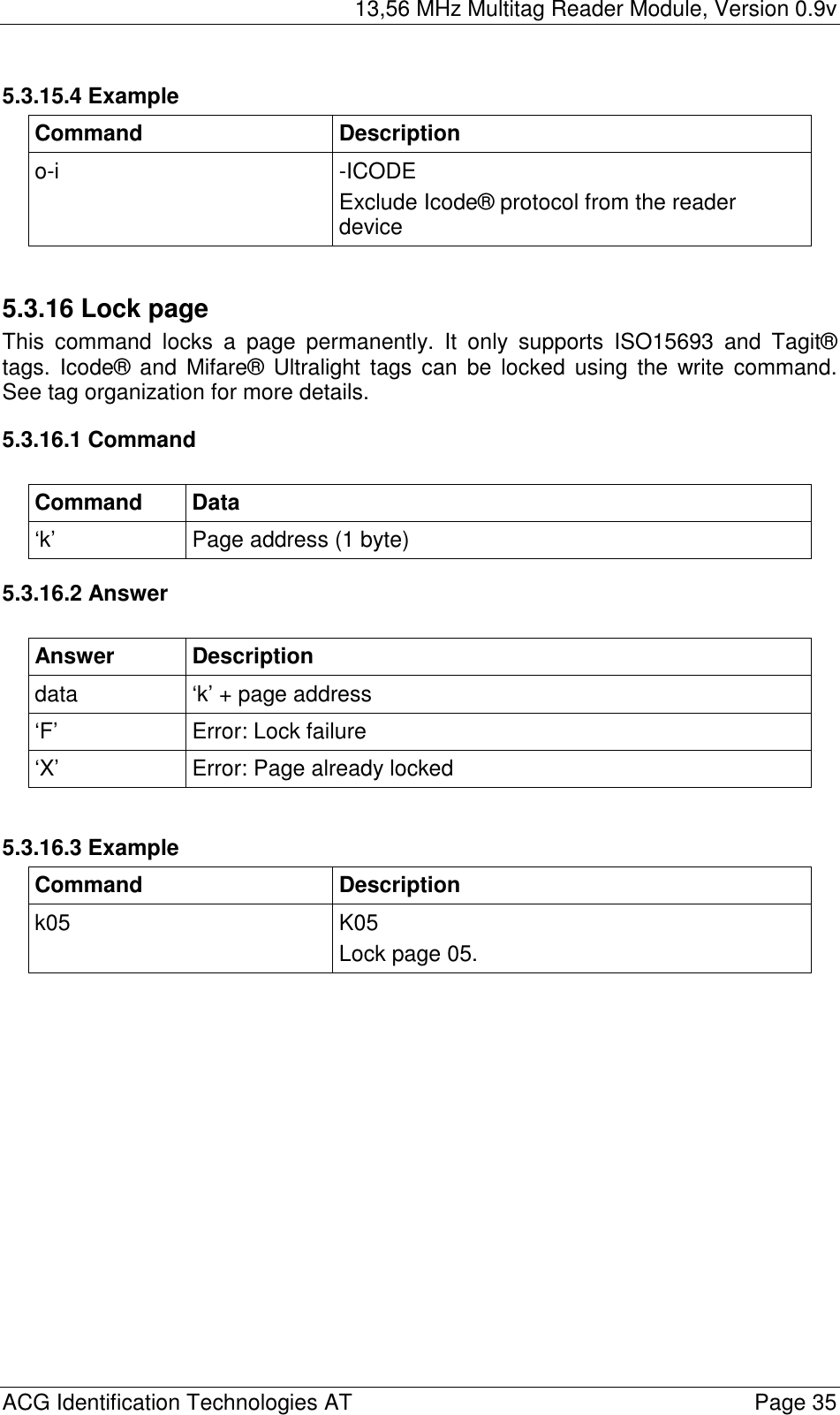
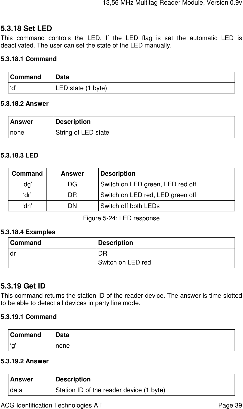
![13,56 MHz Multitag Reader Module, Version 0.9v ACG Identification Technologies AT Page 43 6 Timing The timing is measured between request and response of the reader. Additionally to the process timing the protocol timing must be included. It depends on protocol mode as well as on the baud rate. TimeFail TimeTyp TimeMax Command [ms] [ms] [ms] Reset 5 Power up - 80,0 85,0 Software (x) - 2,98 3,06 Get version (v) - 0,206 - Continuous read (c) 6 All - 13,6 164,0 ISO 15693 - 13,6 14,1 Tagit - 20,4 21,0 Icode - 31,0 32,0 SR176 - 26,4 54,0 ISO 14443 Type A - 18,0 19,0 Ultralight - 26,0 27,0 ISO 14443 Type B - 14,8 15,5 Page read (start up option) All - 22,4 105,0 ISO 15693 - 22,4 23,6 Tagit - 37,6 38,0 Icode - 37,2 38,0 Select (s) All 392,0 20,5 392,0 ISO 15693 50,8 20,5 21,0 Tagit 81,6 20,4 21,0 Icode 116,0 31,0 32,0 SR176 54,8 26,4 54,0 ISO 14443 Type A 43,8 18,0 19,0 Ultralight 43,8 26,0 27,0 5 Reset will cause an error if reader IC Initialization fails 6 Continuous read will only return successful readings](https://usermanual.wiki/ASSALOY-Identification-Technologies/H102022RFPCHR.Users-Manual-Part-1/User-Guide-367116-Page-44.png)