ASSALOY Identification Technologies H102022RFPCHR PCMCIA Compact Flash Card Reader (RF-ID) User Manual Part 2
ASSA ABLOY Identification Technologies GmbH PCMCIA Compact Flash Card Reader (RF-ID) Users Manual Part 2
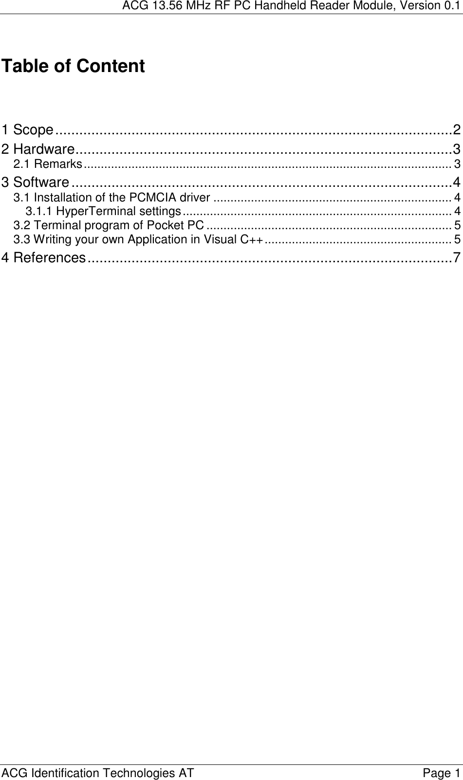
Contents
- 1. Users Manual Part 1
- 2. Users Manual Part 2
Users Manual Part 2
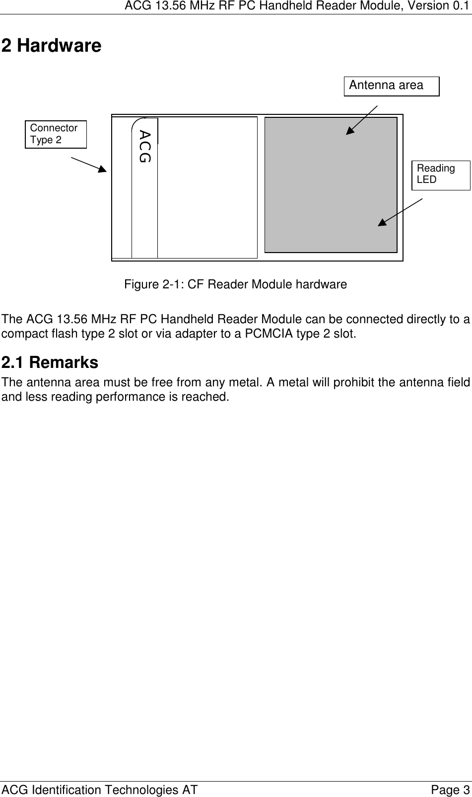
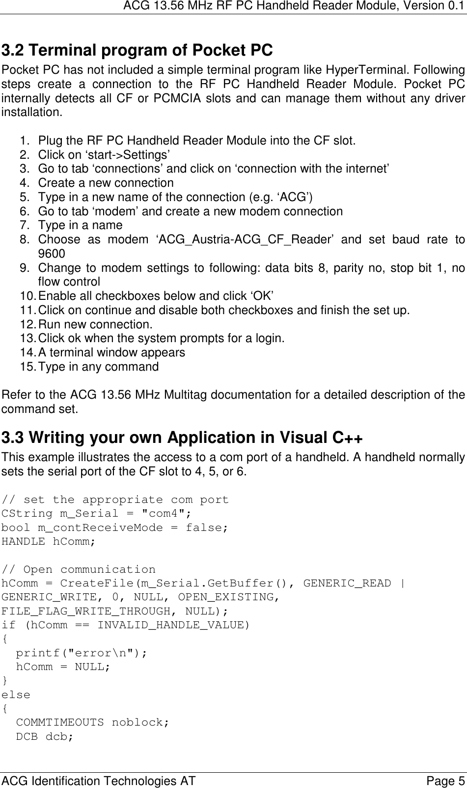
![ACG 13.56 MHz RF PC Handheld Reader Module, Version 0.1 ACG Identification Technologies AT Page 4 3 Software The CF reader module is compatible to the ACG 13.56 MHz Multitag Reader Module. Please refer to the document ACG 13.56 MHz Multitag Reader Module, H102022 [1] for more details of the command set. 3.1 Installation of the PCMCIA driver The RF PC Handheld Reader Module can be connected to a laptop or a PC using an adapter of PCMCIA type 2. 1. First time the module is plugged into the slot the user will be prompt to install a driver. 2. Follow the instructions on the screen. 3. Click on ‘Have Disk…’ to define the driver location manually. 4. Using Windows 98 or Me go to folder ‘ACG CFReader\Win9x’ and double-click on ‘ACGCFR.inf’. 5. Using Windows 2000, NT4 Service Pack4 or XP go to folder ‘ACG CFReader\WINNT’ and double-click on ‘ACGCFR.inf’ 6. Finish the installation The system has loaded all necessary drivers of the ACG 13.56 MHz CF Reader Module. Using a terminal program (e.g. HyperTerminal) the module can be accessed simply. 3.1.1 HyperTerminal settings First you have to connect to the correct COM port. Normally the system sets up COM 4 or COM 5 for the PCMCIA slots. The baud rate depends on the startup settings of the reader device. Default is 9600 baud. Description 8 data bits No parity bit 1 stop bit No flow control Figure 3-1: Communication settings](https://usermanual.wiki/ASSALOY-Identification-Technologies/H102022RFPCHR.Users-Manual-Part-2/User-Guide-367117-Page-5.png)
![ACG 13.56 MHz RF PC Handheld Reader Module, Version 0.1 ACG Identification Technologies AT Page 7 4 References [1] ACG 13.56 MHz Multitag Reader Module Documentation, H102022](https://usermanual.wiki/ASSALOY-Identification-Technologies/H102022RFPCHR.Users-Manual-Part-2/User-Guide-367117-Page-8.png)