ASSALOY Identification Technologies H102022RFPCHR PCMCIA Compact Flash Card Reader (RF-ID) User Manual Part 2
ASSA ABLOY Identification Technologies GmbH PCMCIA Compact Flash Card Reader (RF-ID) Users Manual Part 2
Contents
- 1. Users Manual Part 1
- 2. Users Manual Part 2
Users Manual Part 2

Firmware: 0.1 7/24/2003
ACG Identification Technologies GmbH
Dantestrasse 4-6
65189 Wiesbaden
Germany
Fon +49 (611) 1739.0
Fax +49 (611) 1739.198
www.acg.de rfid@acg-id.net
ACG 13.56 MHz RF PC Handheld
Reader Module
H102022 RF PC Handheld Reader

ACG 13.56 MHz RF PC Handheld Reader Module, Version 0.1
ACG Identification Technologies AT Page 1
Table of Content
1 Scope...................................................................................................2
2 Hardware..............................................................................................3
2.1 Remarks............................................................................................................ 3
3 Software...............................................................................................4
3.1 Installation of the PCMCIA driver ...................................................................... 4
3.1.1 HyperTerminal settings............................................................................... 4
3.2 Terminal program of Pocket PC ........................................................................ 5
3.3 Writing your own Application in Visual C++....................................................... 5
4 References...........................................................................................7

ACG 13.56 MHz RF PC Handheld Reader Module, Version 0.1
ACG Identification Technologies AT Page 2
1 Scope
The ACG 13.56 MHz RF PC Handheld Reader Module is a read write device that
supports a broad range of transponders. It is designed to communicate with
ISO15693, Tagit®, Icode®, SR176, Mifare® Ultralight, ISO14443 Type A and B and
FELICA transponders. With its integrated antenna and compact flash type 2
connector it is ready to use and easily connect into a handheld, laptop or tablet PC.
Using a PCMCIA adapter it can be connected into a PCMCIA slot type 2. The unit
includes a device driver for Windows 98, Me, 2000, NT Service Pack 4 and XP.
This document describes the installation of the device driver and an easy access to
the RF PC Handheld Reader Module. The command set is described in detail in the
document ACG 13.56 MHz Multitag Reader Module and is not listed here.
ACG 13.56 MHz RF PC Handheld Reader Module, Version 0.1
ACG Identification Technologies AT Page 3
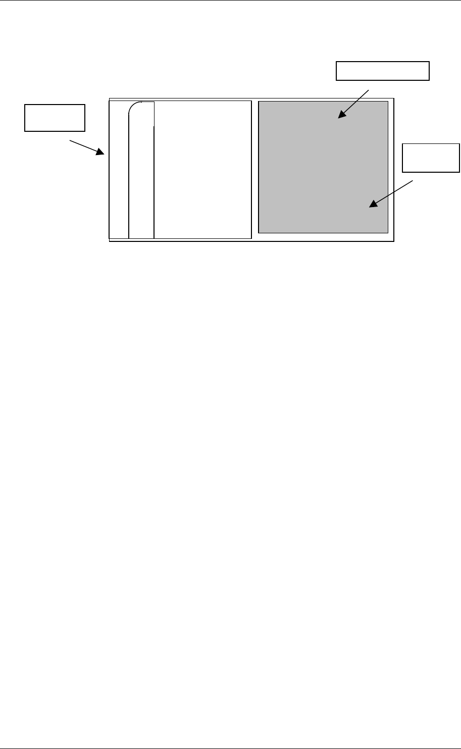
2 Hardware
Figure 2-1: CF Reader Module hardware
The ACG 13.56 MHz RF PC Handheld Reader Module can be connected directly to a
compact flash type 2 slot or via adapter to a PCMCIA type 2 slot.
2.1 Remarks
The antenna area must be free from any metal. A metal will prohibit the antenna field
and less reading performance is reached.
ACG
Connector
Type 2
Reading
LED
A
ntenna area

ACG 13.56 MHz RF PC Handheld Reader Module, Version 0.1
ACG Identification Technologies AT Page 4
3 Software
The CF reader module is compatible to the ACG 13.56 MHz Multitag Reader Module.
Please refer to the document ACG 13.56 MHz Multitag Reader Module, H102022 [1]
for more details of the command set.
3.1 Installation of the PCMCIA driver
The RF PC Handheld Reader Module can be connected to a laptop or a PC using an
adapter of PCMCIA type 2.
1. First time the module is plugged into the slot the user will be prompt to install a
driver.
2. Follow the instructions on the screen.
3. Click on ‘Have Disk…’ to define the driver location manually.
4. Using Windows 98 or Me go to folder ‘ACG CFReader\Win9x’ and double-click
on ‘ACGCFR.inf’.
5. Using Windows 2000, NT4 Service Pack4 or XP go to folder ‘ACG
CFReader\WINNT’ and double-click on ‘ACGCFR.inf’
6. Finish the installation
The system has loaded all necessary drivers of the ACG 13.56 MHz CF Reader
Module. Using a terminal program (e.g. HyperTerminal) the module can be accessed
simply.
3.1.1 HyperTerminal settings
First you have to connect to the correct COM port. Normally the system sets up COM
4 or COM 5 for the PCMCIA slots. The baud rate depends on the startup settings of
the reader device. Default is 9600 baud.
Description
8 data bits
No parity bit
1 stop bit
No flow control
Figure 3-1: Communication settings

ACG 13.56 MHz RF PC Handheld Reader Module, Version 0.1
ACG Identification Technologies AT Page 5
3.2 Terminal program of Pocket PC
Pocket PC has not included a simple terminal program like HyperTerminal. Following
steps create a connection to the RF PC Handheld Reader Module. Pocket PC
internally detects all CF or PCMCIA slots and can manage them without any driver
installation.
1. Plug the RF PC Handheld Reader Module into the CF slot.
2. Click on ‘start->Settings’
3. Go to tab ‘connections’ and click on ‘connection with the internet’
4. Create a new connection
5. Type in a new name of the connection (e.g. ‘ACG’)
6. Go to tab ‘modem’ and create a new modem connection
7. Type in a name
8. Choose as modem ‘ACG_Austria-ACG_CF_Reader’ and set baud rate to
9600
9. Change to modem settings to following: data bits 8, parity no, stop bit 1, no
flow control
10. Enable all checkboxes below and click ‘OK’
11. Click on continue and disable both checkboxes and finish the set up.
12. Run new connection.
13. Click ok when the system prompts for a login.
14. A terminal window appears
15. Type in any command
Refer to the ACG 13.56 MHz Multitag documentation for a detailed description of the
command set.
3.3 Writing your own Application in Visual C++
This example illustrates the access to a com port of a handheld. A handheld normally
sets the serial port of the CF slot to 4, 5, or 6.
// set the appropriate com port
CString m_Serial = "com4";
bool m_contReceiveMode = false;
HANDLE hComm;
// Open communication
hComm = CreateFile(m_Serial.GetBuffer(), GENERIC_READ |
GENERIC_WRITE, 0, NULL, OPEN_EXISTING,
FILE_FLAG_WRITE_THROUGH, NULL);
if (hComm == INVALID_HANDLE_VALUE)
{
printf("error\n");
hComm = NULL;
}
else
{
COMMTIMEOUTS noblock;
DCB dcb;

ACG 13.56 MHz RF PC Handheld Reader Module, Version 0.1
ACG Identification Technologies AT Page 6
// set communication timeout
GetCommTimeouts(hComm, &noblock); // get communication
timeouts
if (m_contReceiveMode == false)
{
// get answer (ReadFile waits for answer until timeout)
// use timeouts, because it is easier to handle
noblock.ReadTotalTimeoutConstant = 2000; // 2 seconds
timeout
noblock.ReadTotalTimeoutMultiplier = MAXDWORD;
noblock.ReadIntervalTimeout = MAXDWORD;
}
else
{
// get answer for polling (immediate return from ReadFile)
noblock.ReadTotalTimeoutConstant = 0;
noblock.ReadTotalTimeoutMultiplier = 0;
noblock.ReadIntervalTimeout = MAXDWORD;
}
if (SetCommTimeouts(hComm, &noblock) == 0) // set
communication timeouts
printf("error\n");
// set communication state
GetCommState(hComm, & dcb);
dcb.BaudRate = 9600;
dcb.ByteSize = 8;
dcb.fParity = FALSE;
dcb.StopBits = ONESTOPBIT;
dcb.fDtrControl = DTR_CONTROL_ENABLE;
dcb.fRtsControl = RTS_CONTROL_DISABLE;
if (SetCommState(hComm, &dcb) == 0)
printf("error\n");
}
/* type in your application here*/
// close communication and free handle
CloseHandle(hComm);
Figure 3-2: Source code of com settings

ACG 13.56 MHz RF PC Handheld Reader Module, Version 0.1
ACG Identification Technologies AT Page 7
4 References
[1] ACG 13.56 MHz Multitag Reader Module Documentation, H102022