User Manual rev1.pdf
A8027G
06/17
Copyright © 2017, Sargent Manufacturing Company, an ASSA ABLOY Group company.
All rights reserved. Reproduction in whole or in part without the express written
permission of Sargent Manufacturing Company is prohibited.
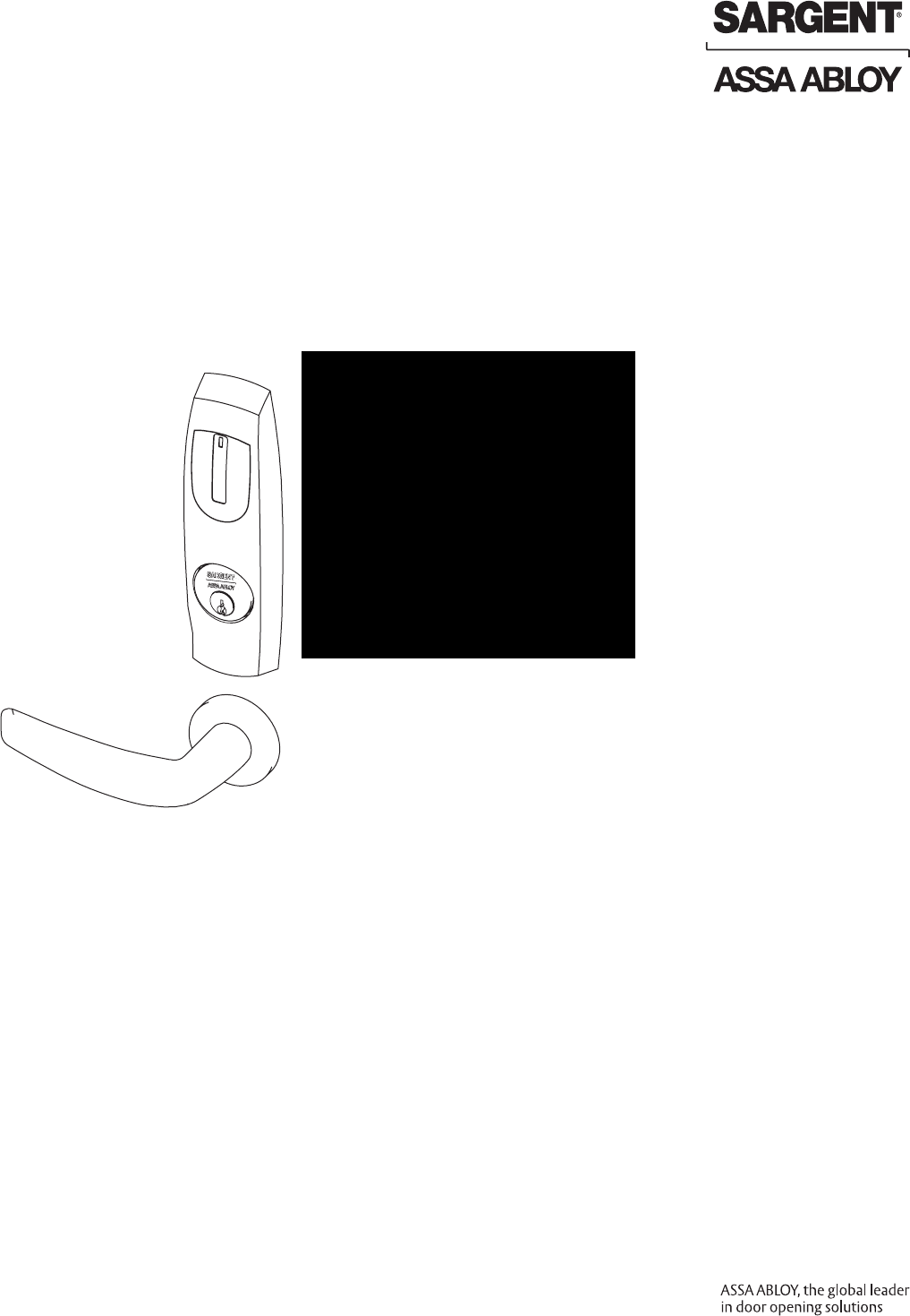
Harmony Series
Mortise Lock
Installation Instructions
H2
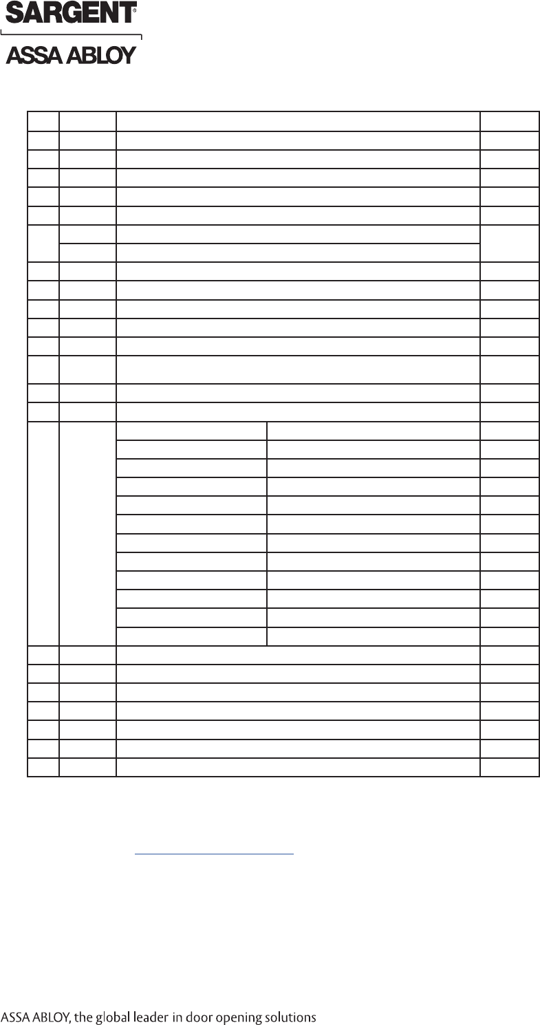
Table of Contents
Warning ...................................................................................2
General Description .................................................................3
Technical Specifications .........................................................3
Regulatory Specifications .......................................................3
Parts Breakdown .....................................................................4
Installation Instructions ..........................................................8
Wiring Diagrams ....................................................................16
Mechanical Operational Check .............................................18
Electrical Operational Check .................................................18
A8027G • 800-810-WIRE (9473) • www.sargentlock.com 2
1
2
3
4
5
6
7
8
9
Changes or modifications to this unit not expressly approved by the party
responsible for compliance could void the user’s authority to operate the equipment.
This device complies with Part 15 of the FCC Rules. Operation is subject to the following two conditions: (1) this device
may not cause harmful interference, and (2) this device must accept any interference received, including interference
that may cause undesired operation.
Note: This equipment has been tested and found to comply with the limits for a Class B digital device, pursuant to
Part 15 of the FCC Rules. These limits are designed to provide reasonable protection against harmful interference in
a residential installation.
This equipment generates, uses and can radiate radio frequency energy and if not installed and used in accordance
with the instructions, may cause harmful interference to radio communications. However, there is no guarantee that the
interference will not occur in a particular installation. If this equipment does cause harmful interference to radio or
television reception, which can be determined by turning the equipment off and on, the user is encouraged to try to
correct the interference by one or more of the following measures:
• Reorient or relocate the receiving antenna
• Increase the separation between the equipment and receiver
• Connect the equipment into an outlet on a circuit different from that to which the receiver is connected
• Consult the dealer or an experienced technician for help
Contains FCC ID: U4A-SCSEHF
Contains IC: 6982A-SCSEHF
The term “IC:” before the radio certification number only signifies that Industry Canada technical specifications were
met. This Class B digital apparatus meets all requirements of the Canadian Interference Causing Equipment Regulations.
Operation is subject to the following two conditions: (1) this device may not cause harmful interference, and (2)
this device must accept any interference received, including interference that may cause undesired operation.
Cet appareillage numérique de la classe B répond à toutes les exigences de l’interférence canadienne causant des
règlements d’équipement. L’opération est sujette aux deux conditions suivantes: (1) ce dispositif peut ne pas causer
l’interférence nocive, et (2) ce dispositif doit accepter n’importe quelle interférence reçue, y compris l’interférence qui
peut causer l’opération peu désirée.
Any retrofit or other field modification to a fire rated opening can potentially impact the fire rating of the opening, and
SARGENT Manufacturing makes no representations or warranties concerning what such impact may be in any specific
situation. When retrofitting any portion of an existing fire rated opening, or specifying and installing a new fire-rated
opening, please consult with a code specialist or local code official (Authority Having Jurisdiction) to ensure compliance
with all applicable codes and ratings.
Warning
1
Observe precautions for handling electrostatic sensitive devices.
!
Copyright © 2017, Sargent Manufacturing Company, an ASSA ABLOY Group company. All rights reserved.
Reproductions in whole or in part without express written permission of Sargent Manufacturing Company is prohibited.
03/31/17
Harmony Series H2 Mortise Lock
A8027G • 800-810-WIRE (9473) • www.sargentlock.com3
The SARGENT Harmony Series H2 mortise lock is designed to interface with existing Wiegand Electronic
Access Control (EAC) panels. The reader requires 12 or 24VDC for power and is compatible with HID®
iCLASS® 13.56MHz technology. Harmony Series technology is backed by SARGENT’s Grade 1 hardware.
The mortise lock comes with Request to Exit (RX) monitoring within the lock body and operates from
12-24VDC. The Harmony H2 iCLASS reader provides visual (LED) and audible indicators of lock position
(locked/unlocked). Gasket required for exterior door applications.
• Latch: Stainless steel, 3⁄4” projection, one-piece
• Deadbolt: One-piece hardened stainless steel
• Guardbolt: Stainless steel, non-handed
• Handed: Easily field reversible without opening case
• Case: 12 gauge heavy duty wrought steel
• Outside lever controlled by any 13.56MHz HID
iCLASS Wiegand credential
• Field-selectable to Fail Safe or Fail Secure
General Description
2
Technical Specifications
3
• Lock to be configured* as Fail Safe or
Fail Secure per AHJ compliance as part of
initial lock configuration
• Locks furnished for 1-3/4” doors. Other door
thicknesses require confirmation with factory.
• UL 294 Access Control Performance Ratings: Destructive Attack Level I
Line Security Level I
Endurance Level IV
Standby Power Level I
• ANSI/BHMA A156.25 Listed Grade 1 Compliant
• UL and CUL listed for use on Fire Doors
• This product meets the requirements of CAN/ULC-S319-05 Equipment Class I
Regulatory Specifications
4
Wiring methods shall be in accordance with the National Electrical Code (ANSI/NFPA70), CSA 22.1, Canadian Electrical
Code (CEC), Part I, Safety Standard for Electrical Installations, local codes, and the authorities having jurisdiction.
• Door position switch within lock body
• Inside lever provides RX signal and retracts
latch and deadbolt
• Reader Draw = 150mA @12VDC / 24VDC
• Actuator Draw = 400mA inrush / 15mA continuous @12VDC / 24VDC
• Solenoid Draw = 250mA @12VDC
500mA @24VDC
03/31/17 Copyright © 2017, Sargent Manufacturing Company, an ASSA ABLOY Group company. All rights reserved.
Reproductions in whole or in part without express written permission of Sargent Manufacturing Company is prohibited.
Harmony Series H2 Mortise Lock
A8027G • 800-810-WIRE (9473) • www.sargentlock.com 4
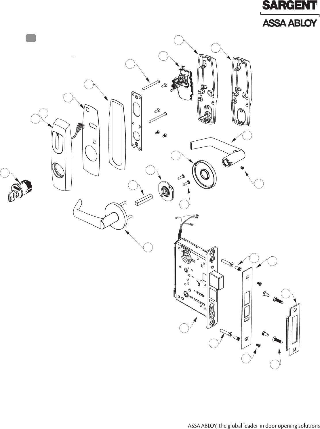
Tools Required:
• Phillips Screw Driver (Standard size)
• Slotted Screw Driver (Standard size)
• 1/8" Allen Wrench
Parts Breakdown
5
15
12
13
1
1A
2
3
5
8
6
9
10
6
6
10
10
16
14*
6
10
7B
7A
7
Copyright © 2017, Sargent Manufacturing Company, an ASSA ABLOY Group company. All rights reserved.
Reproductions in whole or in part without express written permission of Sargent Manufacturing Company is prohibited.
03/31/17
Harmony Series H2 Mortise Lock
A8027G • 800-810-WIRE (9473) • www.sargentlock.com5
Item Part # Description Req.
1 52-4039 Outside Harmony Escutcheon With Cylinder Prep 1
1A 52-4040 Outside Harmony Escutcheon Without Cylinder Prep 1
2 52-0796 Outside Weather Gasket 1
3 52-0795 Inside Weather Gasket 1
5 52-5236 Screw Pack (5A; 5B; 5C; 5D) 1
6 82-4355 Trim Pack - Standard levers 1
79-2162 Trim Pack - Deco levers (shown)
7 52-4517 H2-IA-02 Controller Assembly 1
7A 52-5196 Inside Escutcheon w/ Turn Assembly 1
7B 82-0706 Inside Escutcheon w/out Turn Prep 1
8 -- Reference Harmony Series Catalog For Available Lever Styles 1
9 -- Reference Harmony Series Catalog For Available Rose Styles 1
10 77-4236 Mortise screw pack - specify finish
(includes: wood & metal lock body screws, faceplate screws & strike screws)
12 -- Reference Harmony Series Catalog For Available Lever Styles 1
13 -- Reference Harmony Series Catalog For Available Cylinders (Size 43) 1
14* Lock Body†H2-82270-12/24 VDC x Finish w/out Deadbolt, Fail Safe** 1
H2-82271-12/24 VDC x Finish w/out Deadbolt, Fail Secure** 1
H2-82272-12/24 VDC x Finish w/out Deadbolt, Fail Safe, Both Levers Lock** 1
H2-82273-12/24 VDC x Finish w/out Deadbolt, Fail Secure, Both Levers Lock** 1
H2-82274-12/24 VDC x Finish w/out Deadbolt, Fail Safe** 1
H2-82275-12/24 VDC x Finish w/out Deadbolt, Fail Secure** 1
H2-82280-12/24 VDC x Finish w/ Deadbolt, Fail Safe** 1
H2-82281-12/24 VDC x Finish w/ Deadbolt, Fail Secure** 1
H2-82282-12/24 VDC x Finish w/ Deadbolt, Fail Safe, Both Levers Lock** 1
H2-82283-12/24 VDC x Finish” w/ Deadbolt, Fail Secure, Both Levers Lock** 1
H2-82284-12/24 VDC x Finish w/ Deadbolt, Fail Safe** 1
H2-82285-12/24 VDC x Finish w/ Deadbolt, Fail Secure** 1
15 82-0579 Electrical Outside Faceplate w/ Deadbolt 1
15A 82-0578 Electrical Outside Faceplate w/out Deadbolt 1
16 82-0110 Strike Plate 1
17 01-2299 #12 X 1 1/4" Phillips Flat Head Wood Screw 2
21 A7944 Field Prep Template (Not Shown) 1
22 4590 Door Manufacturer Template (Not Shown) 1
23 A8027 Installation Instructions (Not Shown) 1
Parts Breakdown (Continued)
*Patent Pending - www.assaabloydss.com/patents
**CAUTION: Not recommended for use on any door used for Life Safety Egress
†For End-of-Line Resistor and PHR locks, please consult factory
03/31/17 Copyright © 2017, Sargent Manufacturing Company, an ASSA ABLOY Group company. All rights reserved.
Reproductions in whole or in part without express written permission of Sargent Manufacturing Company is prohibited.
Harmony Series H2 Mortise Lock
A8027G • 800-810-WIRE (9473) • www.sargentlock.com 6
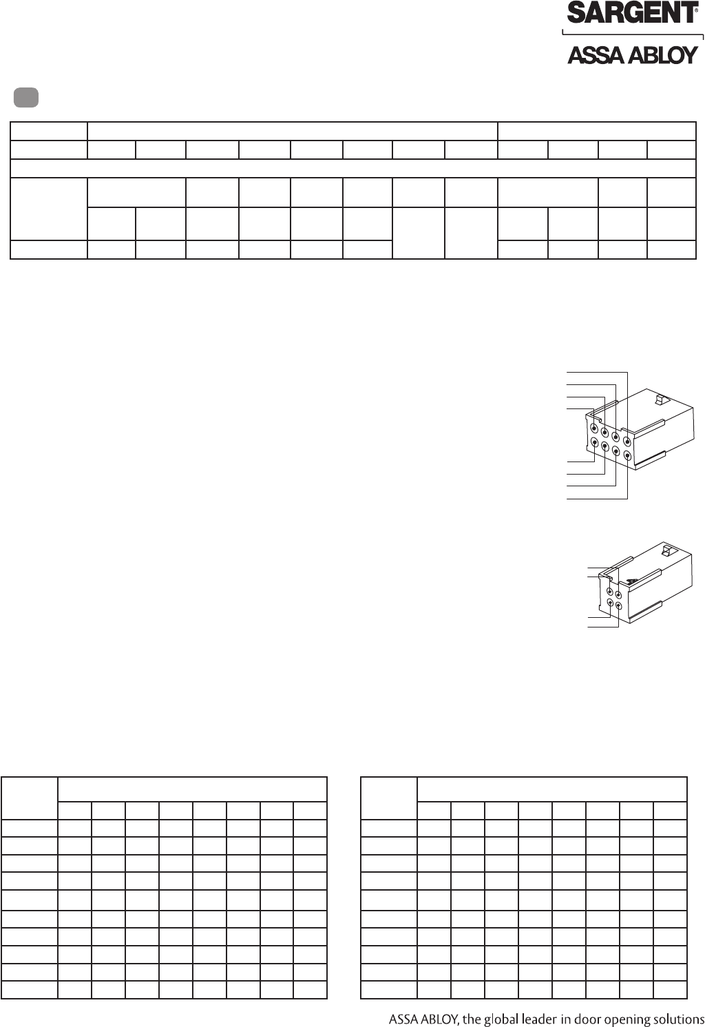
Wiring Diagrams
6
Product 8 PIN CONNECTOR 4 PIN CONNECTOR
1-Black 2-Red 3-White 4-Green 5-Orange 6-Blue 7-Brown 8-Yellow 1-Violet 2-Gray 3-Pink 4-Tan
ACCESS CONTROL DEVICES: Harmony H2 Mortise, ElectroLynx wire Color / Function assignments
SARGENT -
HARMONY
SERIES
H2 Mortise
12/24VDC
(Reader)
WIE-
GAND
WIE-
GAND
RX RX EGND LED 12/24 VDC
(LOCK RELAY)
DPS
(NC)
DPS
(COM)
NEG POS DATA_1 DATA_0 NO/NC COM REF.
*DIA-
GRAMS
REF.
*DIA-
GRAMS
NEG POS DPS DPS
Bored/Exits NEG POS DATA_1 DATA_0 ?? COM NEG POS NC NC
Reader LED Configuration
The Harmony Series reader can be configured for (3) modes of LED
operation. HID Programming cards are also supported to configure
the behavior for LED color activity. Call 1-800-810-WIRE for details.
Mode 1:
• Red LED ‘ON’ when powered.
• Presenting a valid credential causes LED to ‘FLICKER’
green and return to red state.
Mode 2:
• Green LED “ON” when powered.
• No Flicker after presenting valid valid credential.
PIN 8 (Yellow – LED)
PIN 6 (Blue – RX COM)
PIN 4 (Green – Data 0)
PIN 2 (Red – Reader POS)
PIN 1 (Black – Reader NEG)
PIN 3 (White – Data 1)
PIN 5 (Orange – RX NO/NC)
PIN 7 (Brown-EGND)
PIN 4 (Tan – DPS COM)
PIN 2 (Gray – Lock POS)
PIN 1 (Violet – Lock NEG)
PIN 3 (Pink – DPS NC)
Mode 3:
• EAC Panel controls LED operation.
Note: Control of LED is a function of the EAC panel equipment (i.e. relay) to toggle between
green and red.
Note: When LED wire is tied directly into EAC panel relay, no AC signals should be applied on
wire or door reader performance will be impacted.
*Diagram on following page
If your lock is configured with End of Line Resistors, reference instruction sheet A8191 for the wiring of
RX & DPS outputs.
Note: LED wire must be connected to circuit GROUND of
the system’s power supply.
Total
One-Way
Length of
Wire Run (ft)
Load Current @ 12VDC
1/4A 1/2A 3/4A 1A 1-1/4A 1-1/2A 2A 3A
100 20 18 16 14 14 12 12 10
150 18 16 14 12 12 12 10 —
200 16 14 12 12 10 10 — —
250 16 14 12 10 10 10 — —
300 16 12 12 10 10 — — —
400 14 12 10 — — — — —
500 14 10 10 — — — — —
7501210——————
1,000 10 — — — — — — —
1,500 10 — — — — — — —
Wire Gauge Charts
Total
One-Way
Length of
Wire Run (ft)
Load Current @ 24VDC
1/4A 1/2A 3/4A 1A 1-1/4A 1-1/2A 2A 3A
100 24 20 18 18 16 16 14 12
150 22 18 16 16 14 14 12 10
200 20 18 16 14 14 12 12 10
250 18 16 14 14 12 12 12 10
300 18 16 14 12 12 12 10 —
400 18 14 12 12 10 10 — —
500 16 14 12 10 10 — — —
750 14 12 10 10 — — — —
1,000 14 10 10 — — — — —
1,500 12 10 — — — — — —
Wire from EAC panel to door must be shielded with drain terminated at EAC panel controller
Copyright © 2017, Sargent Manufacturing Company, an ASSA ABLOY Group company. All rights reserved.
Reproductions in whole or in part without express written permission of Sargent Manufacturing Company is prohibited.
03/31/17
Harmony Series H2 Mortise Lock
A8027G • 800-810-WIRE (9473) • www.sargentlock.com7
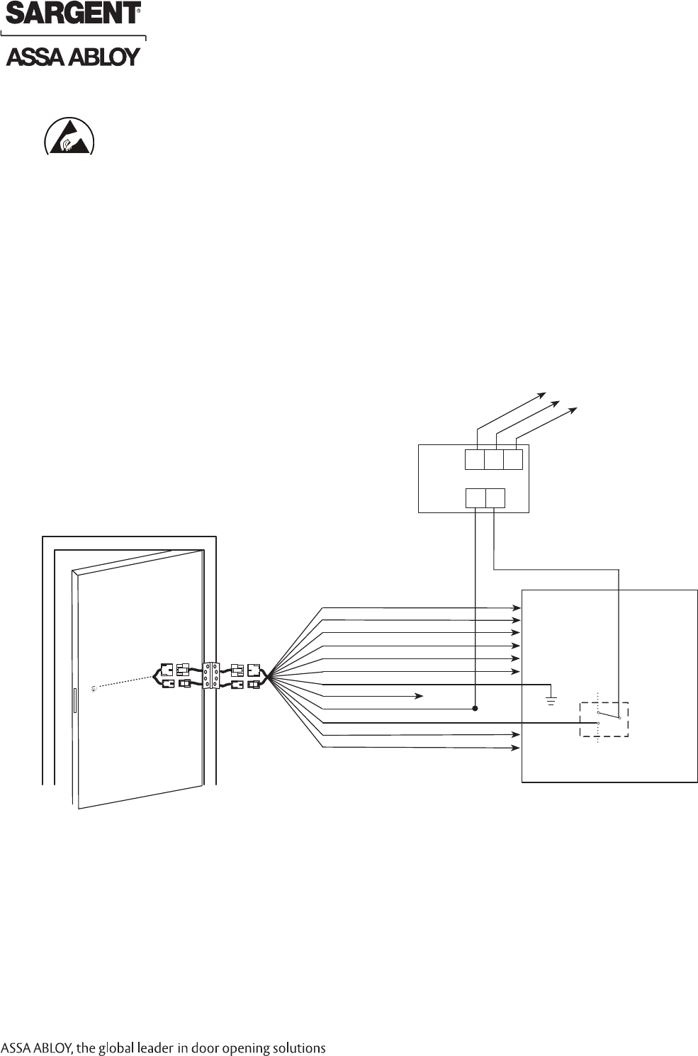
Typical Harmony Mortise Lock Application Diagram (12/24VDC System)
12 Conductor
ElectroLynx Harness
From McKinney
Harmony Series H2
Standard Application Shown - For Alternative Applications Contact 1-800-810-WIRE (9473)
Harmony Series H2
Requires 12 or 24VDC
UL294 Listed Power
Supply (or UL603)
120 VAC
Input 12/24VDC
H N G
- +
Black (Hot)
White (Neutral)
Green (Gnd)
(-)
12/24VDC
(+)
DATA 1
DATA 0
RX
RX
Electronic
Access
Control
Panel
(By Others)
Use (NC) for
Fail Safe
Operation
Lock Relay
(NO) Fail
Secure
Operation
DPS
DPS
Not Used
READER NEG - Black, 1
READER POS - Red, 2
DATA 1 - White, 3
DATA 0 - Green, 4
RX (NO/NC) - Orange, 5
RX (COM) - Blue, 6
*EGND- Brown, 7
LED - Yellow, 8
LOCK NEG - Violet, 9
LOCK POS - Gray, 10
DPS (NC) - Pink, 11
DPS (COM) - Tan, 12
QC12 Electric
Hinge From
McKinney
Lock body
Power Supply
(By Others)
Reader Electronics Require 12 or 24VDC UL294 Listed Power Supply (or UL603)
This product is polarity sensitive; if the lock
does not operate, check the polarity of the
input and reverse if necessary.
12/24VDC System
• Reader Draw = 150mA @12 or 24VDC
• Actuator Draw = 15mA continuous
NOTE:
If your lock is configured with End of Line Resistors,
reference instruction sheet A8191 for the wiring of
RX & DPS outputs.
Harmony Series H2
UL294 Listed EAC
Product
*IMPORTANT: Pin 7 must be tied to earth ground in the access control panel.
Failure to follow proper ESD safe grounding procedures could lead to equipment failure.
03/31/17 Copyright © 2017, Sargent Manufacturing Company, an ASSA ABLOY Group company. All rights reserved.
Reproductions in whole or in part without express written permission of Sargent Manufacturing Company is prohibited.
Harmony Series H2 Mortise Lock
A8027G • 800-810-WIRE (9473) • www.sargentlock.com 8
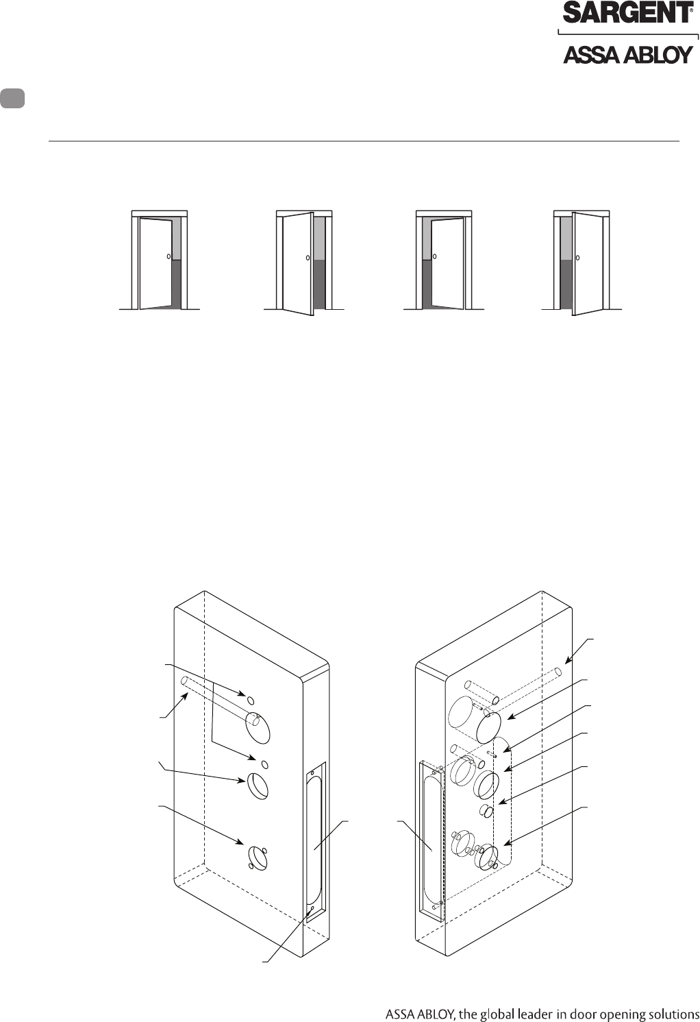
Left Hand
Hinges Left.
Open Inward.
“LH”
Left Hand
Reverse Bevel
Hinges Left.
Open Outward.
“LHRB”
Right Hand
Hinges Right.
Open Inward.
“RH”
Right Hand
Reverse Bevel
Hinges Right.
Open Outward.
“RHRB”
Stand on outside of locked door when determining door hand.
Prepare door according to appropriate template. If necessary, refer to website:
www.intelligentopenings.com.
• Prior to installation, make sure all holes are free of burrs, debris, and sharp edges.
• If doors are not properly reinforced per ANSI 115.2, commercially available reinforcements
should be installed.
• Templates:
• Field prep: A7944 template ships with product.
• Manufacturer: 4590 wood and metal door template.
Outside of Door Inside of Door
Raceway for 12 Conductor
Network/Power Cable
(ElectroLynx) from McKinney
Hole for Cable from
Reader to Controller Board
Pre-drilled and/or
Tapped Holes (2 places)
Inside Cylinder Hole
Through-bolt Holes
(2 places)
Outside Cylinder Hole
(70/71, 80/81
functions only)
Lever Handle Hole
Thumb Turn Hole
Lever Handle Hole
Mortise
Area
Pre-drilled and/or
Tapped Holes (2 Places)
Fig. 1A
Fig. 1B
A. Verify Hand and Bevel of Door
Installation Instructions
6
1 Door Preparation
B. Door Preparation
Wood Door
Raceway for 12 Conductor
Network/Power Cable
(ElectroLynx) from McKinney
Copyright © 2017, Sargent Manufacturing Company, an ASSA ABLOY Group company. All rights reserved.
Reproductions in whole or in part without express written permission of Sargent Manufacturing Company is prohibited.
03/31/17
Harmony Series H2 Mortise Lock
A8027G • 800-810-WIRE (9473) • www.sargentlock.com9
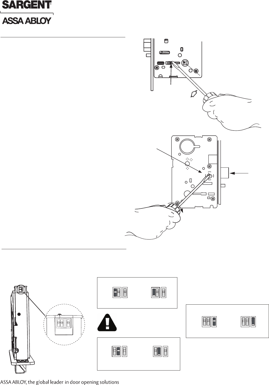
Red surface of locking piece must face the
outside/locked side of door. To rotate locking
piece (Fig. 2A):
1. Position lock body with red surface of
locking piece visible.
2. Insert blade type screwdriver into locking
piece slot to rotate locking piece toward
back of lock body.
3. Rotate the locking piece 180° until RED
surface is on opposite side.
Note: Red indicates locked side (outside).
Beveled surface of latch must face strike (Fig. 2B).
The deadlatch is self adjusting.
To change hand of latchbolt:
1. Insert screwdriver into the spade-
shaped (triangular) slot.
2. Rotate screwdriver 90º to push latch out
until back of latch clears lock front; then
rotate latch 180º.
Latch will then re-enter lock body.
Note: Latch cannot be unscrewed.
Fig. 2A
Locking Guide Slot:
Red color indicates
locked side.
Push In
Right Hand
Lock Shown
2 How to Change Hand of Lock body
A. Reverse Lock Hand
B. Reverse Latch Hand
Triangular Slot
Latchbolt
Fig. 2B
3 Configure the DIP Switch Settings
DIP Switch
1 2 3
Handing
RH & RHR
LH & LHR
Actuator Operation
Fail Safe Fail Secure
RX Output
Normally
Open
Normally
Closed
Check Polarity:
Verify + (red wire)
IMPORTANT: This product is built and factory tested to the
configuration specified. Any change to the 3-position DIP-switch
settings located at the bottom of the mortise lock body must be
made prior to lock installation.
03/31/17 Copyright © 2017, Sargent Manufacturing Company, an ASSA ABLOY Group company. All rights reserved.
Reproductions in whole or in part without express written permission of Sargent Manufacturing Company is prohibited.
Harmony Series H2 Mortise Lock
A8027G • 800-810-WIRE (9473) • www.sargentlock.com 10
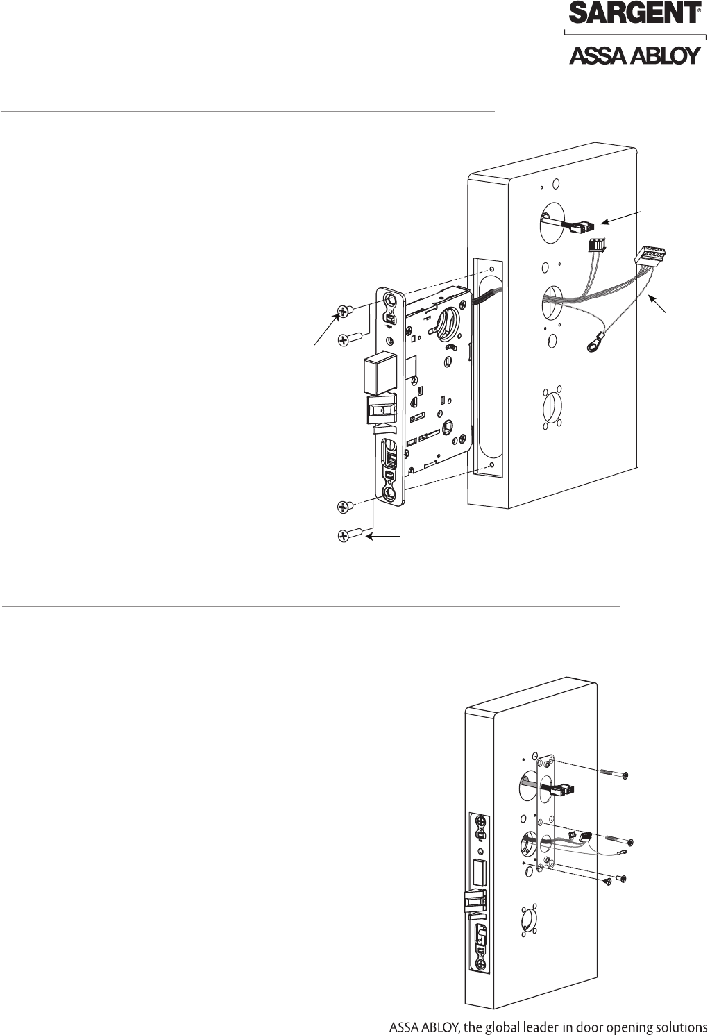
1. Wires and connectors go into the mortised area and out of the
inside cylinder hole.
2. Insert mortise lock body into mortise door preparation.
3. Carefully feed wires from mortise lock through the non-cylinder
side hole of the door preparation.
4. Install appropriate hardware lock body screws.
NOTE: Do not tighten screws completely at this time.
Cylinder should be installed prior to tightening.
Inside of
Door
(2)#12 x 1-1/4” Long Flat Head Wood
Screws (Wood Doors)
Fig. 4
(2) #12-24 x 1/2” Long Flat
Head Philips Screws (Metal Doors)
Feed connectors
and wires through
non-cylinder side.
4 Install Lock body
5 Outside Escutcheon and Mounting Plate Installation
NOTE: Feed mortise connectors through the corresponding hole on the mounting plate.
1. Attach the mounting plate using (2) 8-32 x 2" Phillips flat head
undercut combo screws in the upper right and middle left
positions of the mounting plate and (2) 8-32 x 3/8" Phillips flat head
screws in the bottom positions (Fig. 5A).
Fig. 5A
(2) 8-32 x 3/8” Phillips
Flat Head Undercut
Combo Screw
(2) 8-32 x 3/8”
Phillips Flat
Head Screw
Inside of
Door
12 Conductor
Network/Power
Cable
(ElectroLynx)
from McKinney
Copyright © 2017, Sargent Manufacturing Company, an ASSA ABLOY Group company. All rights reserved.
Reproductions in whole or in part without express written permission of Sargent Manufacturing Company is prohibited.
03/31/17
Harmony Series H2 Mortise Lock
A8027G • 800-810-WIRE (9473) • www.sargentlock.com11
Remember to install inside gasket when
lock is being used in an outdoor application.
1. Add gasket (if necessary):
Gasket fits snug around plate at top and sides,
leaving room for the hole at the bottom.
2. Remove (peel) backing and place gasket
on door (Fig. 6).
6 Install Inside Gasket (if necessary)
Required for exterior
door applications.
Fig. 6
Inside of Door
Fig. 5B
Gasket required
for exterior door
applications
Reader Cable
Outside of Door
2. Feed the reader cable located on the back of the outside
escutcheon through the door prep (Fig. 5B).
3. Outside gasket must be used when installing Harmony in an
outdoor application (Fig. 5B).
4. Secure the mounting plate to the outside escutcheon with
(2) #8-32 x 2” flat head machine screws (Fig. 5C).
5 Outside Escutcheon and Inside Mounting Plate Installation (Continued)
Fig. 5C
Inside of Door
03/31/17 Copyright © 2017, Sargent Manufacturing Company, an ASSA ABLOY Group company. All rights reserved.
Reproductions in whole or in part without express written permission of Sargent Manufacturing Company is prohibited.
Harmony Series H2 Mortise Lock
A8027G • 800-810-WIRE (9473) • www.sargentlock.com 12
Fig. 8B
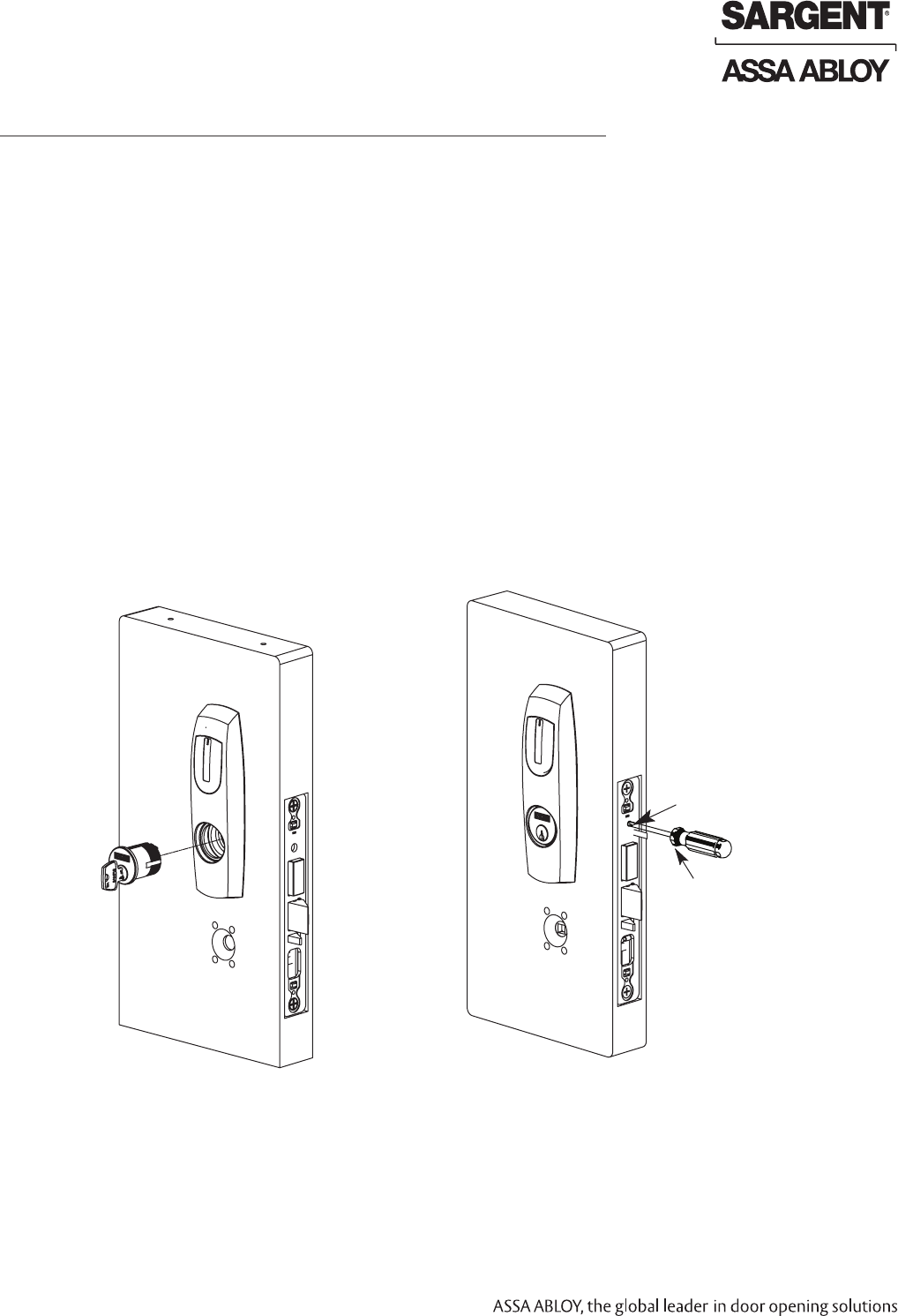
1. Verify orientation of cylinder so that SARGENT logo is right-side up (Fig. 8A).
2. Withdraw the key about 25% out of the cylinder before inserting into the escutcheon (Fig. 8B).
3. Use the key to rotate the cylinder clockwise until it is flush at the bottom and the SARGENT
logo is right-side up.
Do not attempt to tighten all the way.
4. Tighten the cylinder clamp set screw to prevent
unscrewing of the cylinder (Fig. 8C).
5. Test cylinder function:
• 70/71 Function: Key retracts latch.
• 80/81 Function: Key retracts latch
and projects/retracts deadbolt.
• Ensure smooth operation of
latchbolt and deadbolt.
NOTE: Use lever handle holes
to manipulate mortise to ease
thread engagement of cylinder.
Fig. 8C
Cylinder Set Screw
Phillips
Screwdriver
Outside of Door
7 Outside Cylinder Installation
Correct Incorrect
03/31/17 Copyright © 2017, Sargent Manufacturing Company, an ASSA ABLOY Group company. All rights reserved.
Reproductions in whole or in part without express written permission of Sargent Manufacturing Company is prohibited.
Harmony Series H2 Mortise Lock
A8027G • 800-810-WIRE (9473) • www.sargentlock.com 13
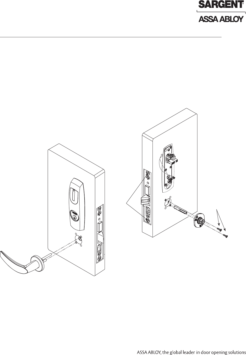
1. With outside lever horizontal, insert the mounting post through outside of door and lock body.
Make certain the lever spindle is properly engaged inside the lock body (Fig. 9A).
2. On the inside of the door, insert slotted spindle into square hole of mortise lock (Fig. 9B),
with spindle slot directed away from the lock body, and aligned with the set screw hole in the
inside adapter.
3. Slide inside adapter and plate assembly over spindle and loosely secure with (2) 8-32 X 5/8”
Phillips oval head and lock washer machine screws.
NOTE: Ensure that position of set screw hole and spinsdle slot are oriented to match location of
hole in the inside lever handle.
4. Securely tighten the lock body screws.
Fig. 9B
Fig. 9A
(2)8-32 X 5/8”
Phillips Oval
Head and
Lock Washer
Machine
Screws
Mortise
Lock body
Screws
Inside of
Door
Outside of
Door
8 Outside Lever and Inside Adapter Plate Assembly Installation
Copyright © 2017, Sargent Manufacturing Company, an ASSA ABLOY Group company. All rights reserved.
Reproductions in whole or in part without express written permission of Sargent Manufacturing Company is prohibited.
03/31/17
Harmony Series H2 Mortise Lock
A8027G • 800-810-WIRE (9473) • www.sargentlock.com14
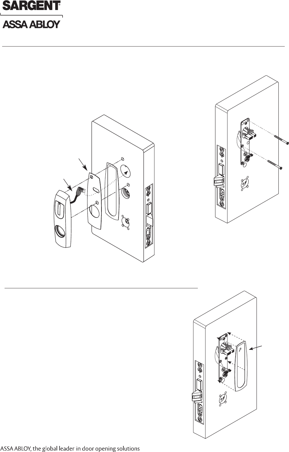
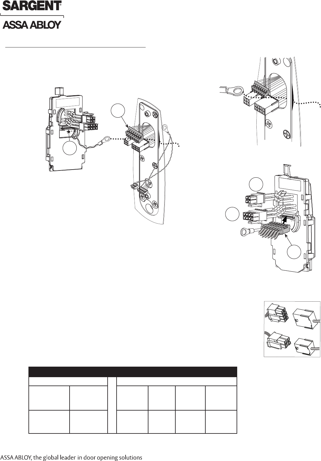
9 Installing Controller
Please follow these steps prior to installing inside escutcheon to
prevent any damage caused by pinching wires:
1. Feed controller harness earth ground into and around behind rim
of large upper hole of the mounting plate (Fig. 10A, B).
Fig. 10B
J1
J2
Earth
ground
b. Connect ElectroLynx harness (4 and 8-pin) from door harness to
ElectroLynx harness on interior PCB assembly (Fig. 10A, D).
NOTES: Neatly fold the wires into the remaining space to prevent
pinching wires when mounting escutcheon.
Do not tuck extra mortise lock body wires back
inside the lock body cylinder hole.
Connectors go on only one way.
Do not offset connector and be sure they are
completely seated.
PCB Layout - Wire Assignments - ElectroLynx Assembly (Molex)
J2 J1
1-Violet Lock Neg
Actuator (+)
Solenoid (-)
3-Pink
DPS (NC)
1- Black
PWR NEG
3-White
DATA 1
5-Orange
RX (NO/NC)
7-Brown
EGND
2-Gray Lock Pos
Actuator (+)
Solenoid (-)
4-Tan
DPS (COM)
2-Red
PWR POS
4-Green
DATA 0
6-Blue
RX (COM)
8-Yellow
LED
Connect ElectroLynx®
P5
8-pin
ElectroLynx
4-pin
ElectroLynx
J5
Fig. 10A
a. Connect P5 (7 Pin Connector) from reader board to J5 on interior
escutcheon PCB assembly (Fig. 10C).
P5
Inside of
Door
Inside of
Door
Fig. 10C
Fig. 10D
Controller PCB
03/31/17 Copyright © 2017, Sargent Manufacturing Company, an ASSA ABLOY Group company. All rights reserved.
Reproductions in whole or in part without express written permission of Sargent Manufacturing Company is prohibited.
Harmony Series H2 Mortise Lock
A8027G • 800-810-WIRE (9473) • www.sargentlock.com 15
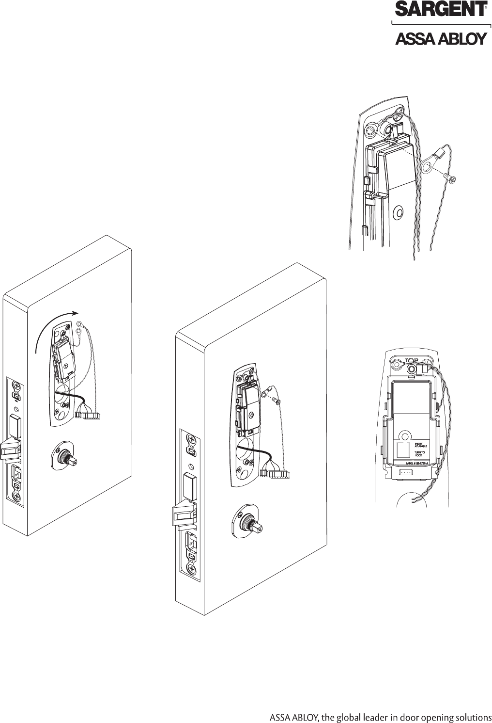
c. Position two-wire green/yellow ground wire ring terminal (from lock body)
over hole for top
left screw (Fig. 11B, C).
d. Position green/yellow reader harness earth ground on top of two-wire
ground ring and thread both with (1) 8-32 x 3/8” Phillips flat head undercut
combo screw (Fig. 11C, D).
IMPORTANT: Note orientation of ground ring terminals in Fig. 11B-D.
e. Tighten securely.
Fig. 11B
Once wires are arranged, position controller at a rotated angle against the door,
under earth ground wire.
a. Press piece against door while turning clockwise (Fig. 11A).
b. Twist into place, perpendicular with door (Fig. 11B).
Install Controller
Inside of
Door
Rotate Clockwise
Fig. 11A
(2) 8-32 x 3/8” Phillips
Flat Head Undercut
Combo Screw
Fig. 11C
Fig. 11D
Copyright © 2017, Sargent Manufacturing Company, an ASSA ABLOY Group company. All rights reserved.
Reproductions in whole or in part without express written permission of Sargent Manufacturing Company is prohibited.
03/31/17
Harmony Series H2 Mortise Lock
A8027G • 800-810-WIRE (9473) • www.sargentlock.com16
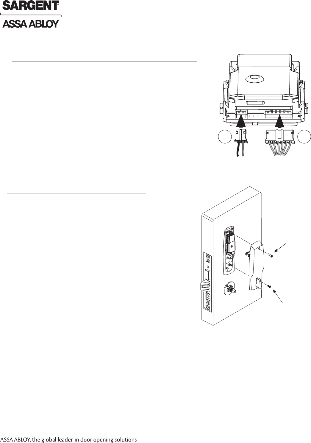
1. Connect P3 (2-pin connector) from lock body
to J3 on module (Fig. 12).
2. Connect P4 (6-pin connector) from lock body
to J4 on module (Fig. 12).
12 Connector Attachment (Exterior PCB Assembly)
13 Install Inside Escutcheon Assembly
1. Tighten the inside escutcheon securely to the
mounting plate with the Phillips flat head machine
screws provided.
Use the 8-32 x 5/8” for the top of the escutcheon
and the 8-32 x 1/4” screws for the bottom of the
escutcheon located under the turn lever (Fig. 13).
NOTE: The inside gasket (not shown) must be used
when installing Harmony in an outdoor application
(refer to previous Step 6).
2. Be sure the turn assembly is functional
and the deadbolt functions properly.
Fig. 13
8-32 X 1/4” Phillips
Flat Head Undercut
Machine Screw
8-32 X 5/8” Phillips
Flat Head Undercut
Machine Screw
Inside of Door
P4 P3
Copyright © 2017, Sargent Manufacturing Company, an ASSA ABLOY Group company. All rights reserved.
Reproductions in whole or in part without express written permission of Sargent Manufacturing Company is prohibited.
03/31/17
Harmony Series H2 Mortise Lock
A8027G • 800-810-WIRE (9473) • www.sargentlock.com17
Fig. 14A Fig. 14B
Set Screw
Inside Lever
Spindle
Inside of Door
Rose
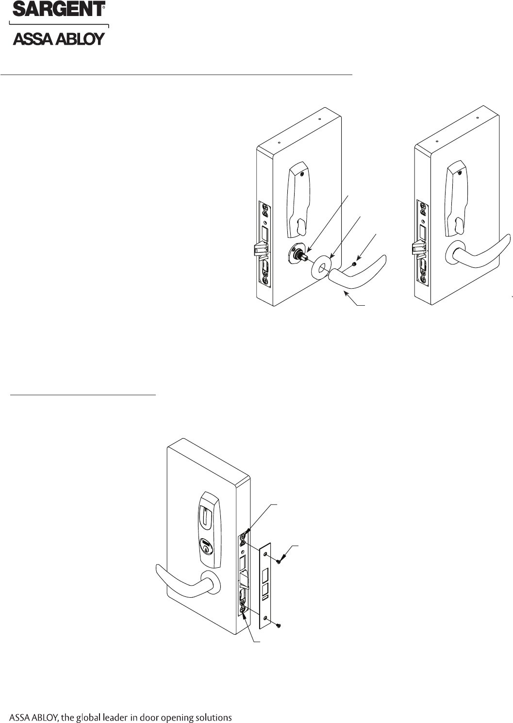
14 Inside Rose and Inside Lever Assembly Instructions
1. Attach front plate with (2) 8-32x1/4” flat head screws
and tighten securely.
Fig. 15
(2) 8-32x1/4”
Flat Head Screws
Lock Body Screw
Lock Body Screw
Outside of Door
15 Attach Front Plate
1. Rotate the inside rose - first counter clock
wise to seat the threads and then, clockwise
to securely tighten.
2. Slide lever handle onto spindle until fully
seated. Be sure handle is horizontal and
facing the hinge side of the door. Push lever
onto spindle so minimum gap is visible.
3. Tighten the set screw securely with
a 1/8” hex wrench.
4. Before closing the door, test that
lever is functional and ensure
smooth operation of the
latchbolt and deadbolt.
03/31/17 Copyright © 2017, Sargent Manufacturing Company, an ASSA ABLOY Group company. All rights reserved.
Reproductions in whole or in part without express written permission of Sargent Manufacturing Company is prohibited.
Harmony Series H2 Mortise Lock
A8027G • 800-810-WIRE (9473) • www.sargentlock.com 18
For 82280-82283 & 82270-82273 Function mortise locks with cylinders:
1. Insert key into cylinder and rotate: There should be no friction against
lock case, wire harness or any other obstructions.
2. The key will retract the latch: Key should rotate freely.
3. When the deadbolt is thrown: Ensure that the key retracts both the
deadbolt and the latch.
4. Inside lever: When used, ensure it retracts both the latch
and deadbolt (if provided).
5. Close door: Ensure latch and deadbolt fully extend
and do not bind.
Note: Once electrical wiring has been successfully
completed according to proper application, follow
the following steps:
1. Turn power ON.
2. Verify LED located on reader is ON (Red or Green
depending on reader configuration (See reader LED
Configuration).
3. Present proximity credential and verify LED and
sounder activity.
4. Verify valid card read at EAC panel.
5. Verify system operation functions; i.e., present valid Prox credential
to reader and unlock door.
Mechanical Operational Check
9
Electrical Operational Check
10
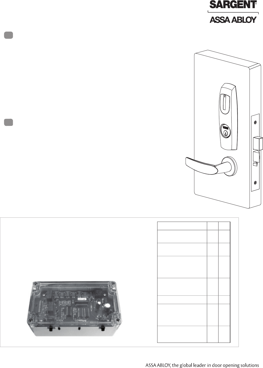
Feature WT1 WT2
12 or 24VDC solenoid
lock voltage adjustable X X
Operates as Fail Safe or
Fail Secure X X
"Learn" mode allows
testing of specific cards
without programming at
the panel level
X X
Card reader data inte-
grity is validated at test
unit
X X
Works with SE LP10 X X
Displays detailed
Wiegand data, including
hexadecimal string and
total bits received
X
Displays measured end-
of-line resistor values
(if applicable)
X
The ASSA ABLOY Wiegand Test Unit verifies your installation in
the field. The test unit checks for proper wiring, card reader data
integrity, lock functionality including lock/unlock, door position
status, and request-to-exit (REX) status.
In addition, this tool provides product demonstration abilities to
highlight the product’s features and capabilities.
Wiegand Test Unit

A8027G-06/17
SARGENT Manufacturing
100 Sargent Drive
New Haven, CT 06511 USA
800-727-5477 • www.sargentlock.com
Founded in the early 1800s, SARGENT® is a market leader in locksets, cylinders, door closers, exit devices,
electro-mechanical products and access control systems for new construction, renovation, and replacement applications.
The company’s customer base includes commercial construction, institutional, and industrial markets.
Copyright © 2017, Sargent Manufacturing Company, an ASSA ABLOY Group company. All rights reserved.
Reproduction in whole or in part without the express written permission of Sargent Manufacturing Company is prohibited.
Sargent Manufacturing Company (New Haven, CT). 2017. Patent pending and/or patent - www.assaabloydss.com/patents.
HID, iCLASS, and Edge are trademarks or registered trademarks of HID Global Corporation.
ASSA ABLOY is the global leader in door opening solutions, dedicated to
satisfying end-user needs for security, safety and convenience.