ASSALOY SCYICLS2 Microprocessor Controlled Networked Locks User Manual XX XXXX Exhibit Cover
ASSA ABLOY Inc. Microprocessor Controlled Networked Locks XX XXXX Exhibit Cover
ASSALOY >
Contents
- 1. P1 Manual
- 2. P2 Manual
- 3. TCP Manual
TCP Manual

5015 B.U. Bowman Drive Buford, GA 30518 USA Voice: 770-831-8048 Fax: 770-831-8598
Certification Exhibit
FCC ID: U4A-SCYICLS2
IC: 6982A-SCYICLS2
FCC Rule Part: 15.225
IC Radio Standards Specification: RSS-210
ACS Report Number: 11-0071.W06.11.A
Manufacturer: Assa Abloy, Inc.
Model: TCPIP-M819/M820,TCPWI-M819/M820
Manual
700™
Installation Instructions
ML20700 TCPWI1 & TCPIP1Series
Mortise Lockset FM324 04/11
Please read these instructions carefully to prevent missing important steps.
Please Note: Improper installations may result in damage to the lock and void the factory warranty.
Important: The accuracy of the door preparation is critical for proper functioning and security of this lock.
Misalignment can cause premature wear and a lessening of security.
For Technical Assistance call Corbin Russwin at 1-800-810-WIRE (9473)
Copyright © 2011 Corbin Russwin, Inc., an ASSA ABLOY Group company.
All rights reserved. Reproduction in whole or in part without the
express written permission of Corbin Russwin, Inc. is prohibited.
Attention Installer
TCPWI1/TCPIP1
PRELIMINARY

ML20700 PWI/PIP Series Mortise Lock
2
Copyright © 2011 Corbin Russwin, Inc., an ASSA ABLOY Group company.
All rights reserved. Reproduction in whole or in part without the
express written permission of Corbin Russwin, Inc. is prohibited.
1) Warning
Table of Contents
1) Warning ................................................................................2
2) General Description .............................................................3
3) Specifications / Features ....................................................3
4) Product Illustration .............................................................4
5) Installation Instructions ......................................................5
6) TCPIP (PoE) Wiring Instructions........................................19
7) Operational Check .............................................................22
Warning: Changes or modifications to this unit not expressly approved by the party
responsible for compliance could void the user’s authority to operate the equipment.
!
TCPWI1 FCC NOTE: This equipment has been tested and found to comply with the limits for a Class B digital device, pursuant to Part
15 of the FCC Rules. These limits are designed to provide reasonable protection against harmful interference in a residential installation.
This equipment generates, uses, and can radiate radio frequency energy and, if not installed and used in accordance with the instruc-
tions, may cause harmful interference to radio communications. However, there is no guarantee that interference will not occur in a par-
ticular installation. If this equipment does cause harmful interference to radio or television reception, which can be determined by turning
the equipment off and on, the user is encouraged to try to correct the interference by one or more of the following measures:
• Reorient or relocate the receiving antenna.
• Increase the separation between the equipment and receiver.
• Connect the equipment into an outlet on a circuit different from that to which the receiver is connected.
• Consult the dealer or an experienced radio/TV technician for help.
Statement: The term “IC:” before the radio certification number only signifies that Industry Canada
technical specifications were met.
This Class B digital apparatus meets all requirements of the Canadian Interference Causing Equipment Regulations. Operation is subject
to the following two conditions: (1) this device may not cause harmful interference, and (2) this device must accept any interference
received, including interference that may cause undesired operation.
Cet appareillage numérique de la classe B répond à toutes les exigences de l’interférence canadienne
causant des règlements d’équipement. L’opération est sujette aux deux conditions suivantes: (1) ce
dispositif peut ne pas causer l’interférence nocive, et (2) ce dispositif doit accepter n’importe quelle
interférence reçue, y compris l’interférence qui peut causer l’opération peu désirée.
TCPIP1 FCC NOTE: This equipment has been tested and found to comply with the limits for a Class A digital device, pursuant to part
15 of the FCC rules. These limits are designed to provide reasonable protection against harmful interference when the equipment is
operated in a commercial environment. This equipment generates, uses, and can radiate radio frequency energy and, if not installed and
used in accordance with the instruction manual, may cause harmful interference to radio communications. Operation of this equipment
in a residential area is likely to cause harmful interference in which case the user will be required to correct the interference at his own
expense.
Industry Canada: The term “IC:” before the radio certification number only signifies that Industry Canada technical specifications were
met.
This Class A digital apparatus meets all requirements of the Canadian Interference Causing Equipment Regulations. Operation is subject
to the following two conditions: (1) this device may not cause harmful interference, and (2) this device must accept any interference
received, including interference that may cause undesired operation.
Cet appareillage numérique de la classe A répond à toutes les exigences de l’interférence canadienne causant des règlements
d’équipement. L’opération est sujette aux deux conditions suivantes: (1) ce dispositif peut ne pas causer l’interférence nocive, et (2) ce
dispositif doit accepter n’importe quelle interférence reçue, y compris l’interférence qui peut causer l’opération peu désirée.
PRELIMINARY

ML20700 PWI/PIP Series Mortise Lock
3
Copyright © 2011 Corbin Russwin, Inc., an ASSA ABLOY Group company.
All rights reserved. Reproduction in whole or in part without the
express written permission of Corbin Russwin, Inc. is prohibited.
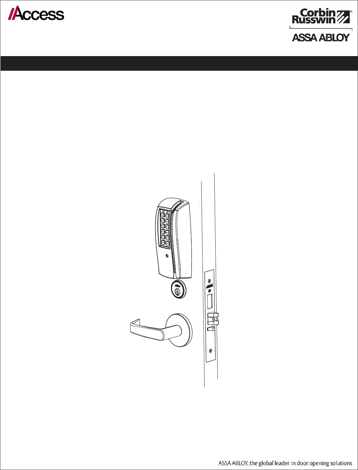
Designed specifically for the campus market, the Corbin Russwin Access 700 series mortise Locks are available
in WiFi (PWI) and PoE (PIP) configurations. Coupled with third party software the PWI and PIP offers a complete,
integrated access control system. The Access 700 may be used for both indoor and outdoor applications (weath-
er-protective gasket supplied).
HID and iCLASS are registered trademarks of HID Global Corporation.
2) General Description
3) Specifications / Features
Hardware Specifications
• Latch – Stainless Steel (Easily field reversible without disassembling lockbody)
• Deadbolt – Stainless Steel
• Door Thickness – 1-3/4” Standard; can be furnished for other door thicknesses upon request. Consult factory.
• Case – 12 gauge heavy duty wrought steel
• Outside lever controlled by any combination of keypad, magnetic swipe, iCLASS reader, or mechanical key.
• Inside lever retracts latch
• BHMA Grade 1; UL Fire Listed
• Outside lever for iCLASS controlled by HID iCLASS crendtial or other 13.56 MHz credential (such as CSN,
Chip Serial Number, read only supported, including MiFare, DesFire, and FeliCa.
Electrical Specifications:
• 2400 users per lock; 10,000 event audit trail
• Multiple time zone and holiday access scheduling
• First-In unlock configuration, either by time or by valid time or by user (selectable)
• Use existing magstripe ID cards (high or low coercivity)
• Card Coercivity: HiCo (400 Oersted) or LoCo (300 Oersted)
• Supports 13.56 MHz iCLASS credentials (26-39 bit); supports CSN reads for other common 13.56 MHZ
including MiFare, DesFire, and FeliCa.
TCPWI - Wireless
WiFi 802.11 b/g
DC9V, 1.5A (6 AA Alkaline Batteries or Electrical Power)
TCPIP - PoE
Class 1 Device, as defined by IEEE 802.3af, requires up to 4 watts over structured cabling
To comply with “Fire Listed” doors, the batteries must be replaced with alkaline batteries only.
Observe precautions for handling electrostatic sensitive devices.
!
PRELIMINARY
ML20700 PWI/PIP Series Mortise Lock
4
Copyright © 2011 Corbin Russwin, Inc., an ASSA ABLOY Group company.
All rights reserved. Reproduction in whole or in part without the
express written permission of Corbin Russwin, Inc. is prohibited.
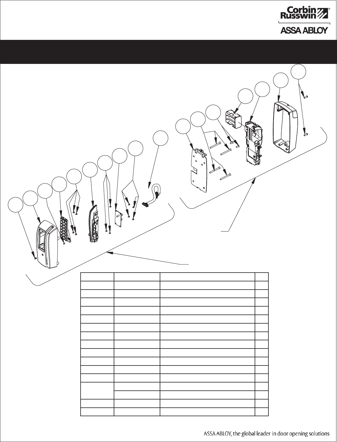
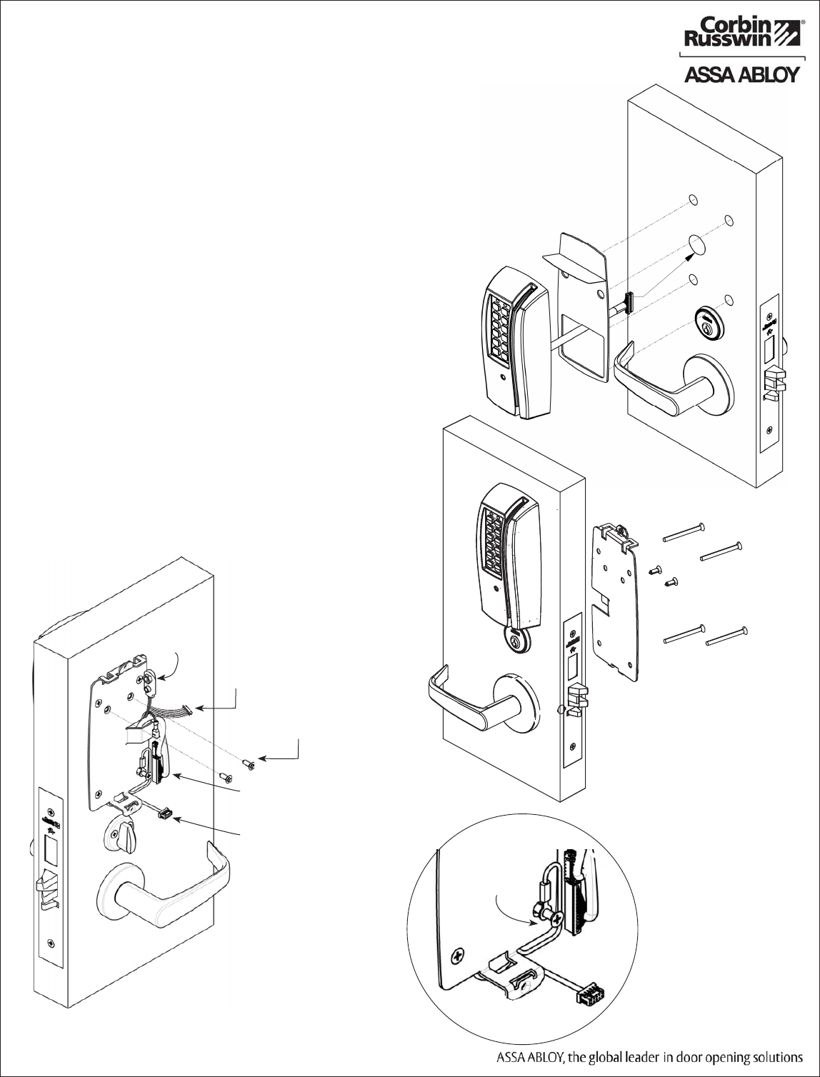
4) Product Illustration-
PoE Lock with Magnetic Card Swipe, 125 kHz Prox and Keypad
9
11
12
13
14
1
2
4
6
7
3
5
5
10
11
5
8
Inside
Outside
ITEM No. PART No. DESCRIPTION QTY
1 795F069 Light Pipe Lens 1
2 795F145 FIN Escutcheon, O/S, PWI With Keypad 1
2 795F135 FIN Escutcheon, O/S, PWI Without Keypad 1
3 795F059 Light Pipe 1
4 795F039 Keypad Assy 1
5 795F318 Screw #4-40x1/4 11
6 795F849 Swipe Reader 1
7 795F859 Onine Interface PCB 1
8 795F079 Online Harness 1
9 795F088 Mounting Plate 1
10 323F818 Screw, #8-32 x 2 4
11 743F768 Screw, #8 x 3/8 2
12 795F839 Electronics, Access 700PWI 1
795F829 Electronics, Access 700PIP 1
13 795F105 FIN Escutcheon, I/S 1
14 795F197 Screw, #8-32 x 1/2” Torx-Pin 2
PRELIMINARY
ML20700 PWI/PIP Series Mortise Lock
5
Copyright © 2011 Corbin Russwin, Inc., an ASSA ABLOY Group company.
All rights reserved. Reproduction in whole or in part without the
express written permission of Corbin Russwin, Inc. is prohibited.
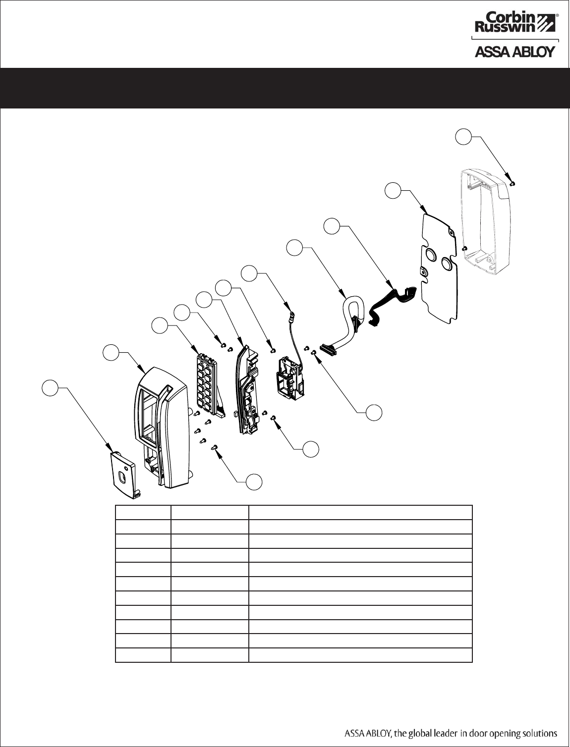
4) Product Illustration-
Magnetic Card Swipe With 13.56 MHz iCLASS and Keypad (M820)
ITEM No. PART No. DESCRIPTION
1 741F579 Outside Mask Assembly
2 741F555 x FIN Outside Escutcheon - iCLASS
3 795F039 Slim Style Keypad Assembly
4 795F318 #4-40 x 3/16” Machine Screw
5 741F599 Swipe Reader Assembly
6 741F549 iCLASS Module Assembly
7 795F079 Harness Assembly
8 741F589 iCLASS Harness
9 741F568 Back Plate
10 795F328 #4-32 x 5/16” Plastite Screw
1
2
3
4
5
10
4
4
4
9
8
7
6
4
PRELIMINARY
ML20700 PWI/PIP Series Mortise Lock
6
Copyright © 2011 Corbin Russwin, Inc., an ASSA ABLOY Group company.
All rights reserved. Reproduction in whole or in part without the
express written permission of Corbin Russwin, Inc. is prohibited.
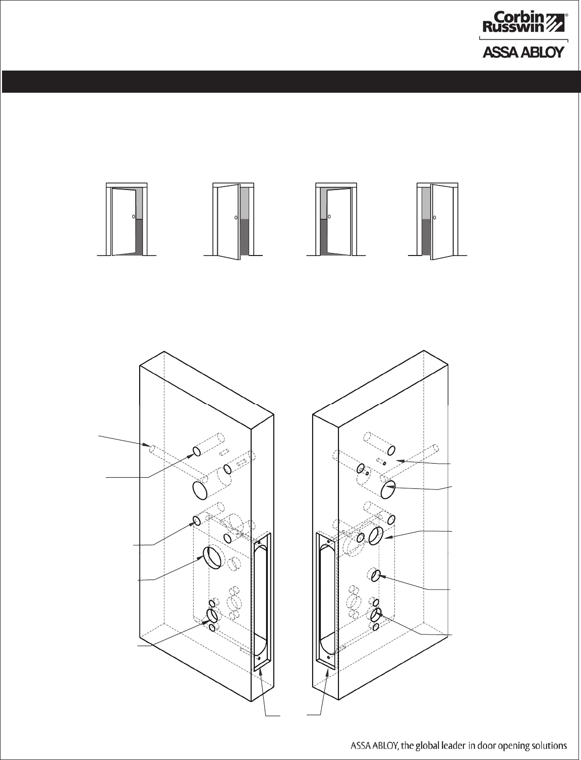
1. Verify Hand and Bevel of door:
Illustrations shown are as viewed from the outside or secure side of opening.
5) Installation Instructions
2. Prep door according to door template T31167 : visit www.corbinrusswin.com.
Left Hand
Hinges Left.
Open Inward.
“LH”
Left Hand
Reverse Bevel
Hinges Left.
Open Outward
“LHRB”
Right Hand
Hinges Right.
Open Inward.
“RH”
Right Hand
Reverse Bevel
Hinges Right.
Open Outward
“RHRB”
Outside of Door
Backplate Mount Holes
Lock Harness Hole
Mortise
Pocket
Keypad Cable Holes
Thumb Turn Hole
Lever Handle Holes
Inside of Door
Lever Handle Holes
Through Bolt Holes
Through Bolt Holes
Cylinder Hole
Remote Power and POE
Raceway
PRELIMINARY
ML20700 PWI/PIP Series Mortise Lock
7
Copyright © 2011 Corbin Russwin, Inc., an ASSA ABLOY Group company.
All rights reserved. Reproduction in whole or in part without the
express written permission of Corbin Russwin, Inc. is prohibited.
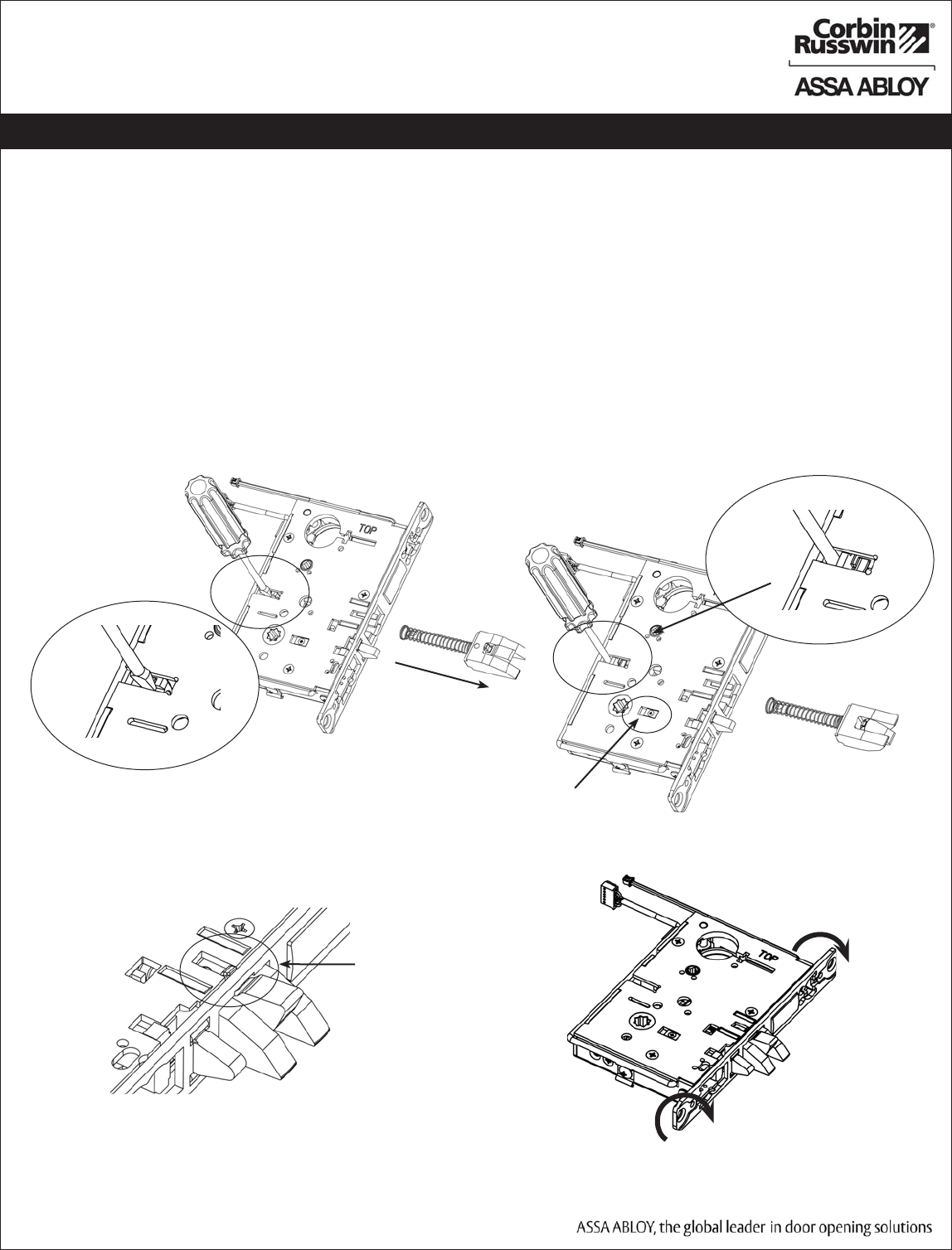
5) Installation Instructions (Continued)
3. Handing of Lock Body:
If necessary re-hand latch and move RED locking screw to side of lockbody to side of lock
body to be locked:
a. Push in latch while gently pushing on catch plate with screwdriver (Fig. 3a).
b. Release latch and remove from lock body.
c. Turn over latch and re-install in lock body; Be sure anti-friction latch tail hooks into front (Fig. 3c).
d. Hold screwdriver behind tail socket while pushing in latch. Push latch until ‘click’ is heard (Fig. 3b).
Note: Pull on latch to make sure it is secure.
e. Rotate lock front to match bevel of door by inserting screwdriver into lock mounting holes
and twisting (Fig. 3d).
Fig. 3a Fig. 3b
Move the RED-HEADED screw to
the Locking Side of the door
Fig. 3c
Anti-friction Latch 0Tail
Fig. 3d
Lock Front
PRELIMINARY
ML20700 PWI/PIP Series Mortise Lock
8
Copyright © 2011 Corbin Russwin, Inc., an ASSA ABLOY Group company.
All rights reserved. Reproduction in whole or in part without the
express written permission of Corbin Russwin, Inc. is prohibited.
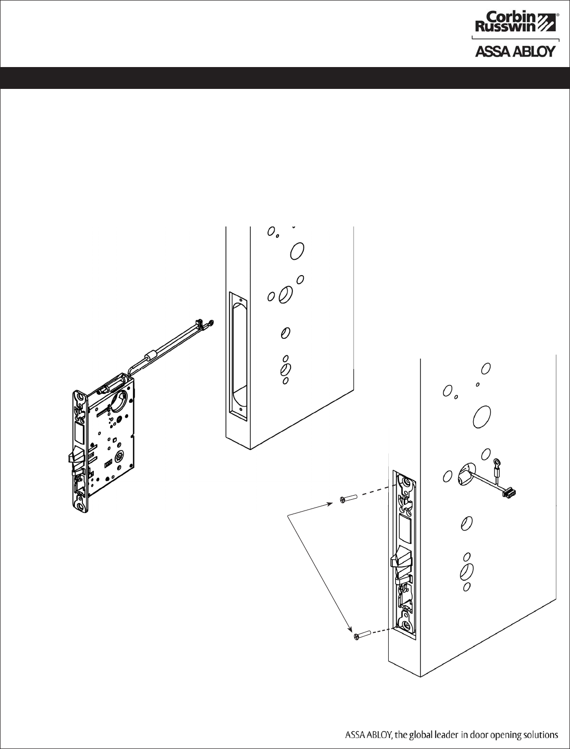
Fig. 4a
5) Installation Instructions (Continued)
4. Install Lock Body into Door:
a. Feed wires through hole on INSIDE of door while installing lock body (Fig. 4a).
b. Pull wires through hole while inserting lockbody (Fig. 4b).
DO NOT push wires back into cylinder hole.
IMPORTANT: Door must remain open during installation. Use door stop.
c. Install, but do not tighten two #12 x 1” combination screws through lock body (Fig. 4b).
(2) #12 Comination Screws
Inside Face of Door
Fig. 4b
PRELIMINARY
ML20700 PWI/PIP Series Mortise Lock
9
Copyright © 2011 Corbin Russwin, Inc., an ASSA ABLOY Group company.
All rights reserved. Reproduction in whole or in part without the
express written permission of Corbin Russwin, Inc. is prohibited.
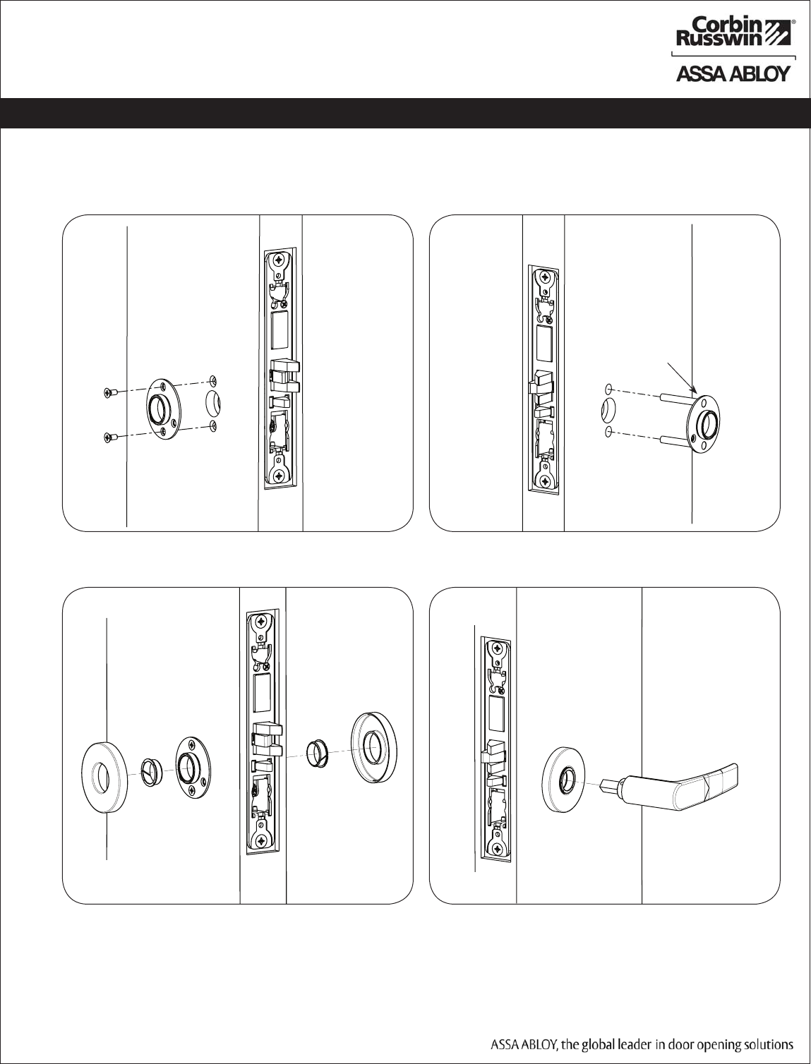
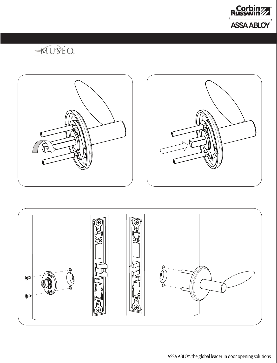
5) Installation Instructions (Continued)
5. Install Standard Lever Trim Instructions:
Step 2 Step 3
Step 1a Step 1b
Inside Face of Door Outside Face of Door
Outsode Face of Door
Outsdide Adapter Plate
Inside Face of Door
PRELIMINARY
ML20700 PWI/PIP Series Mortise Lock
10
Copyright © 2011 Corbin Russwin, Inc., an ASSA ABLOY Group company.
All rights reserved. Reproduction in whole or in part without the
express written permission of Corbin Russwin, Inc. is prohibited.
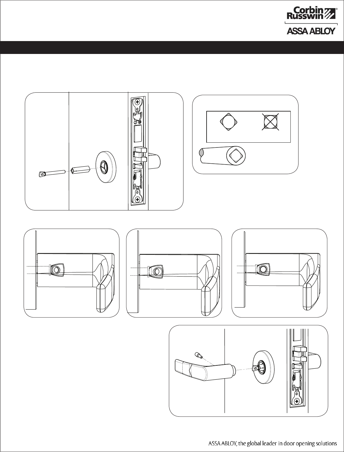
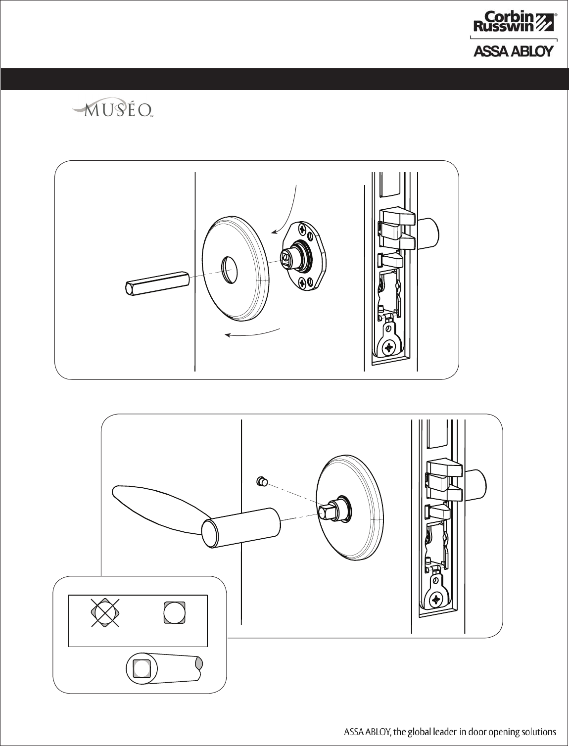
5) Installation Instructions (Continued)
Inside Face of Door
Step 4A
Step 5 - Align adjustment bolt with threaded hole in lever
Adjustment bolt needs
to be threaded in farther.
Adjustment bolt needs
to be unthreaded.
Adjustment bolt
fully aligned.
Notes:
• Unthread Adjustment Bolt approximately four turns
for a good starting point (After being fully tightened)
• Make sure O/S lever is fully inserted into adapter
plate before aligning adjustment bolt.
Step 6
STANDARD MUSÉO
Use Correct Spindle Orientation
Good Bad
Lever
5. Install Standard Lever Trim Instructions (continued):
Step 4B
Inside Face of Door
PRELIMINARY
ML20700 PWI/PIP Series Mortise Lock
11
Copyright © 2011 Corbin Russwin, Inc., an ASSA ABLOY Group company.
All rights reserved. Reproduction in whole or in part without the
express written permission of Corbin Russwin, Inc. is prohibited.
Step 1
Step 2
Inside Face of Door
Outside Face of Door
Thread hub into
lever using spindle
until snug
Unthread hub 1/2
turn then push
spindle into lever
6. Install Lever Trim:
5) Installation Instructions (Continued)
PRELIMINARY
ML20700 PWI/PIP Series Mortise Lock
12
Copyright © 2011 Corbin Russwin, Inc., an ASSA ABLOY Group company.
All rights reserved. Reproduction in whole or in part without the
express written permission of Corbin Russwin, Inc. is prohibited.
Outside Face of Door
14b. Install Trim:
5) Installation Instructions (Continued)
STANDARD MUSÉO
Lever
Use the Correct Spindle Orientation
Bad Good
Lever
Step 3
6. Install Trim (continued):
Inside Face of Door
Set screw in hub faces
away from door edge
Step 4
PRELIMINARY
ML20700 PWI/PIP Series Mortise Lock
13
Copyright © 2011 Corbin Russwin, Inc., an ASSA ABLOY Group company.
All rights reserved. Reproduction in whole or in part without the
express written permission of Corbin Russwin, Inc. is prohibited.
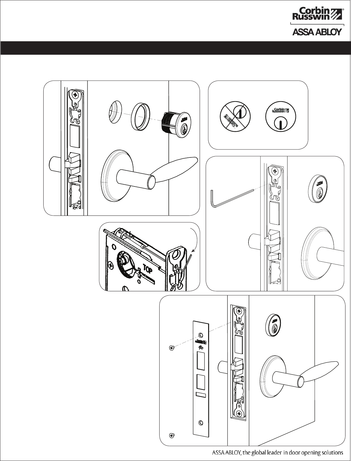
Outside Face of Door
7/64" Allen Wrench
Key and cylinder
must be rotated.
Incorrect Correct
Step 1
14b. Install Trim:
5) Installation Instructions (Continued)
Step 2
Step 3
7. Install Cylinder and Scalp:
PRELIMINARY
ML20700 PWI/PIP Series Mortise Lock
14
Copyright © 2011 Corbin Russwin, Inc., an ASSA ABLOY Group company.
All rights reserved. Reproduction in whole or in part without the
express written permission of Corbin Russwin, Inc. is prohibited.
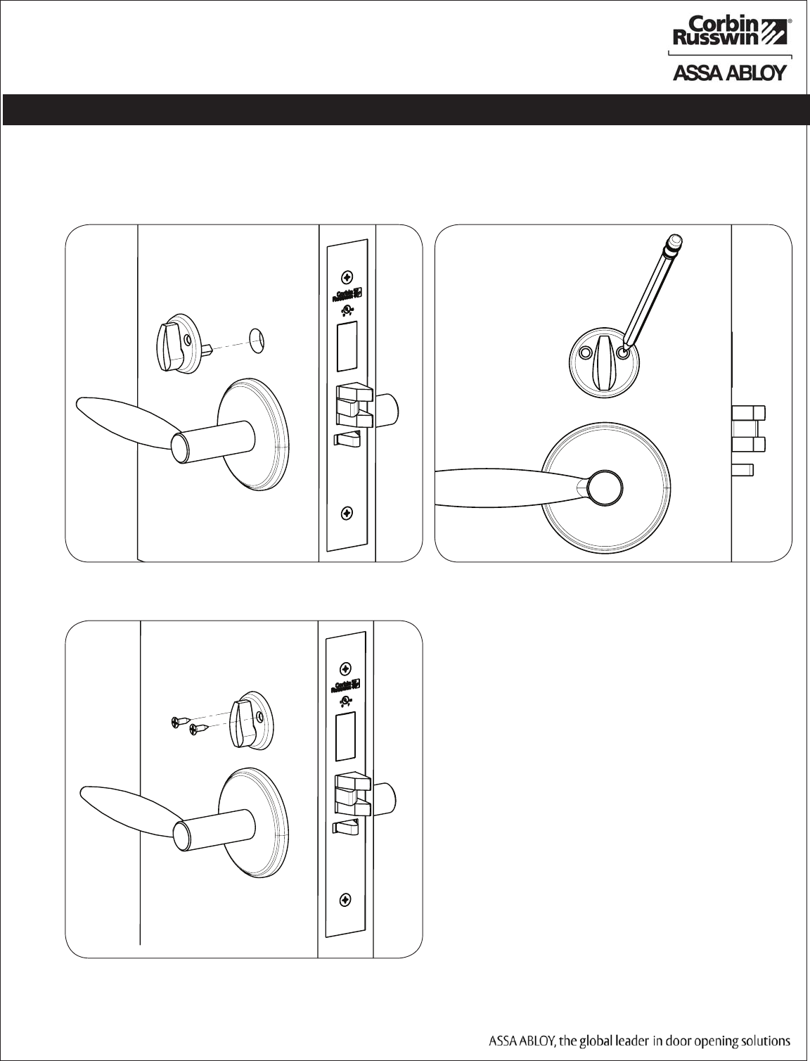
Step 1
8. Install Turn Piece:
5) Installation Instructions (Continued)
Step 2
Step 3
PRELIMINARY
ML20700 PWI/PIP Series Mortise Lock
15
Copyright © 2011 Corbin Russwin, Inc., an ASSA ABLOY Group company.
All rights reserved. Reproduction in whole or in part without the
express written permission of Corbin Russwin, Inc. is prohibited.
9. Install (optional) Weatherseal Gasket:
For non-fire rated door applications, an optional gasket may be
used as a weatherseal between the escutcheon and the
outside door surface.
Peel off the adhesive backing on the gasket and
install the gasket along the edge of the outside
escutcheon assembly (Fig. 9a).
10. Install Inside Mounting Plate:
Install face plate using four
#8-32 machine screws.
IMPORTANT: For fire rated doors,
also use two #8 surface
mount screws. Correctly position
the lock body harness and ground
wire.
(2) #8 Surface Mount Screws
Required for Fire Rated Doors
(4) #8-32
Machine Scews
Outside Face of Door
Fig. 10a
Surface
Mount
Screws
Ground Wire
With Ring Terminal
TCPWI
Only
Weatherseal Gasket
Outside Escutcheon
Fig. 9a
Reader Cable
M820- iCLASS
only
Surface
Mount
Screws
Lock Cable
PRELIMINARY
ML20700 PWI/PIP Series Mortise Lock
16
Copyright © 2011 Corbin Russwin, Inc., an ASSA ABLOY Group company.
All rights reserved. Reproduction in whole or in part without the
express written permission of Corbin Russwin, Inc. is prohibited.
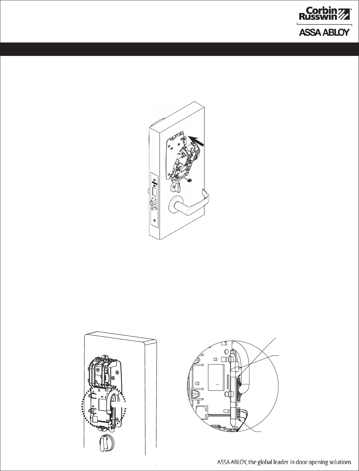
5) Installation Instructions (Continued)
13. Attach PWI Connectors (For PIP skip to Step 15):
Secure the following connectors to the circuit board as shown (Fig. 13a and 13b Detail).
a. Secure the mortise lock body assembly connector (10-pin).
b. Secure the mortise keypad/card reader connector (24-pin).
Note: Connectors go on only one way. Do not force and do not offset connector.
Be sure they are seated (completely flush).
c. Secure the 9-pin reader cable (M820- iCLASS only).
IMPORTANT: Door must remain open duing installation. Use door stop.
Fig. 13b Detail
From
Outside
Trim
From
Lockbody
Detail 13b
Fig. 13a
Fig. 12a
12. Install Electronics Module:
a. Insert the single tab on the electronics module into the single tab at the bottom of the mounting plate.
b. Tilt the module upward and secure the top two tabs into the mounting plate (Fig. 12a).
9-pin Reader Cable
(iCLASS Only)
PRELIMINARY
ML20700 PWI/PIP Series Mortise Lock
17
Copyright © 2011 Corbin Russwin, Inc., an ASSA ABLOY Group company.
All rights reserved. Reproduction in whole or in part without the
express written permission of Corbin Russwin, Inc. is prohibited.
5) Installation Instructions (Continued)
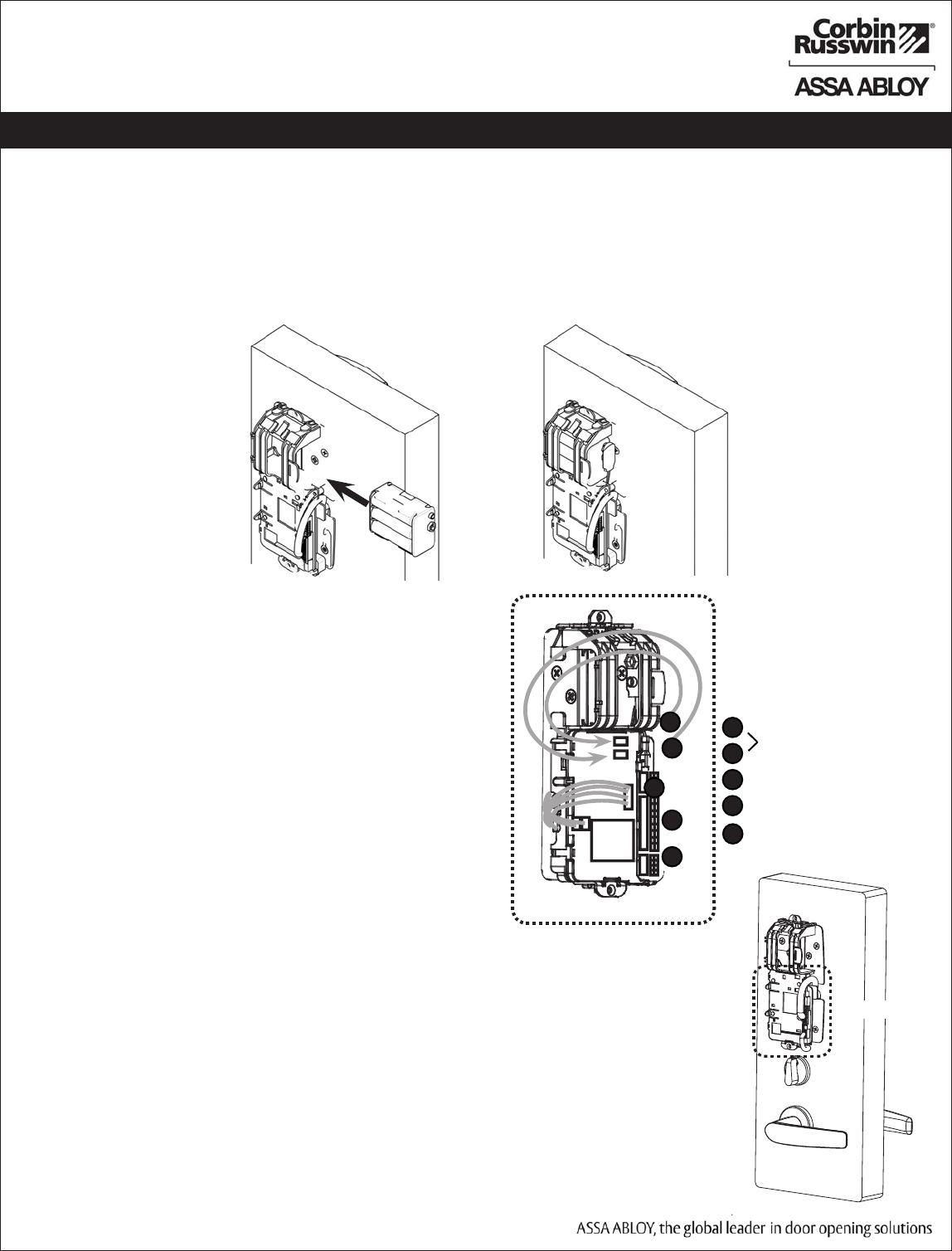
14. PWI Battery/ Battery Pack Installation (For PIP skip to Step 15):
a. Place (6) “AA” batteries into the compartment being careful to align polarity (- & +) according to case
markings (Fig. 13a).
b. Insert battery pack and click into place, making sure polarity terminals on the battery pack are oriented
upward (Fig. 13b).
Fig. 14a Fig. 14b
15. Attach PIP Connectors:
Secure the following connectors onto the circuit board
(Fig. 15A and 15B):
1. Secure the 10-pin lock body assembly connector (e).
2. Secure the 24-pin keypad/card reader connector (d).
3. Secure two 4-pin PoE connectors (b and c).
4. Secure 9-pin reader cable (M820- iCLASS only).
Route wires from behind backplate through battery
compartment.
Notes:
• Connectors go on only one way.
• Do not force and do not offset connectors.
• Be sure they are completely seated (flush).
Detail 15B
Fig. 15b Detail
Fig. 15a
(2) 4-Pin PoE
connectors
e
d
b
c
24-pin from reader
10-pin from lock body
e
d
c
b
f9-pin reader cable (iCLASS
only)
f
PRELIMINARY
ML20700 PWI/PIP Series Mortise Lock
18
Copyright © 2011 Corbin Russwin, Inc., an ASSA ABLOY Group company.
All rights reserved. Reproduction in whole or in part without the
express written permission of Corbin Russwin, Inc. is prohibited.
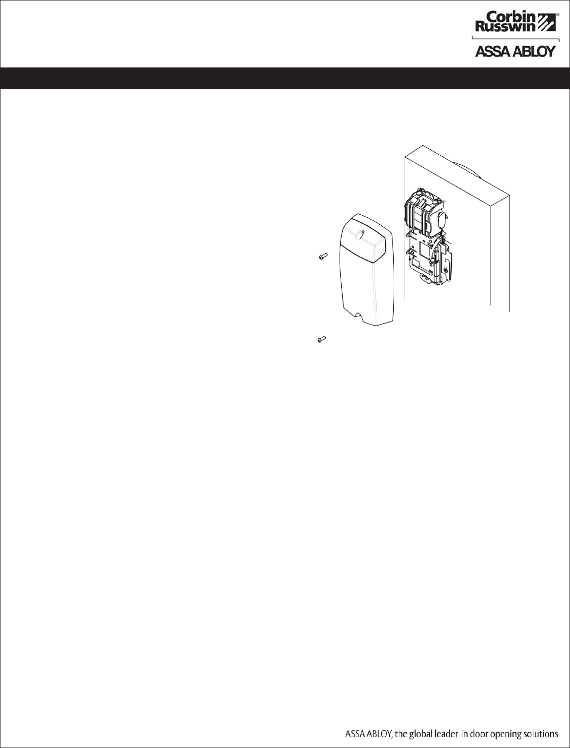
Fig. 16a
16. Install Inside Escutcheon:
Install escutcheon using two #8-32 T20 Security
Torx Screws.
Be careful not to pinch wires under escutcheon.
5) Installation Instructions (Continued)
PRELIMINARY

ML20700 PWI/PIP Series Mortise Lock
19
Copyright © 2011 Corbin Russwin, Inc., an ASSA ABLOY Group company.
All rights reserved. Reproduction in whole or in part without the
express written permission of Corbin Russwin, Inc. is prohibited.
Important Note: Wiring Installation
If you are installing PIP (PoE) please go to Page 19 PIP Installation Wiring
If you are installing PWI please go to Page 21 Operational Check
Continue With Installation...
PRELIMINARY
ML20700 PWI/PIP Series Mortise Lock
20
Copyright © 2011 Corbin Russwin, Inc., an ASSA ABLOY Group company.
All rights reserved. Reproduction in whole or in part without the
express written permission of Corbin Russwin, Inc. is prohibited.
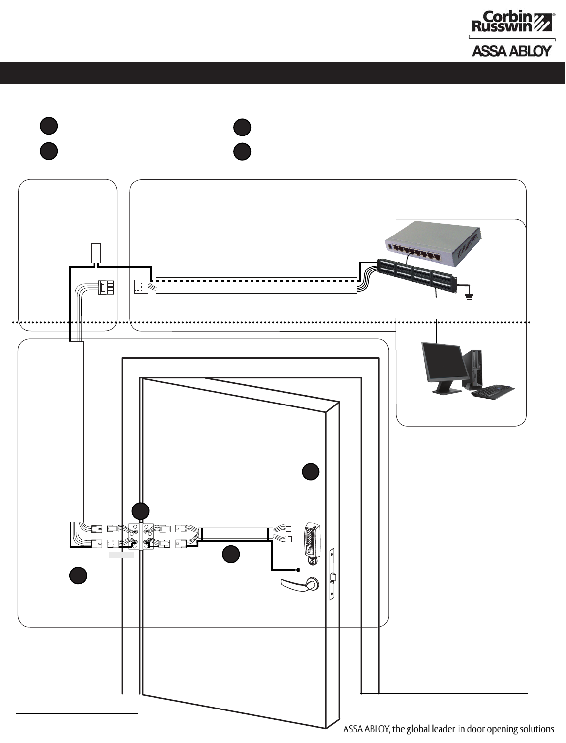
Cable: CAT 5e or higher
24 AWG shielded with drain wire
JST
4-Pin
Molex-F Molex-F Molex-M
Cable: CAT 5e,
26 AWG stranded,
shielded, 100ohm
TIA/EIB-568-B Standard Wiring
RJ45-M
Molex-M
RJ45-F Jack
Cable: CAT 5e or higher
24 AWG shielded, 100ohm
Approved Software
B-Splice
Crimp Connector
Certified Integrator (CI) supplies and terminates
the B-Splice connector and the
Male RJ45 connector from harness to
end user provided facility cable
Supplied by End User
PoE Switch
PoE
Lock
Ceiling
Supplied by CI
C
B
A
PoE Patch Panel
Drain Wire Terminated on Rack
D
Ground
Ring Terminal
Secured to Lock
Mounting Plate
Drain Wire PoE Switch
Rack is
Terminated to
Earth Ground
Patch Cable:
PoE Panel to
PoE Switch
4-Pin
Molex
A. PoE Frame harness assembly
(From McKinney)
B. PoE data hinge (Patent Pending)
(From McKinney)
C. PoE Door harness*
(From McKinney)
D. Access 700 PIP (PoE Lock)
* Order of installation may vary.
Refer to appropriate sections for instructions.
Frame-Side
Harness
Assembly
(15' length)
24AWG
Stranded
Drain
Wire for
Earth
Ground in
15' Frame
Harness
Cable drain
wire con-
cealed in
shrink tubing
6) PIP (PoE) Installation Wiring
17. PIP (PoE) Installation Wiring:
A
B
C
D
PRELIMINARY
ML20700 PWI/PIP Series Mortise Lock
21
Copyright © 2011 Corbin Russwin, Inc., an ASSA ABLOY Group company.
All rights reserved. Reproduction in whole or in part without the
express written permission of Corbin Russwin, Inc. is prohibited.
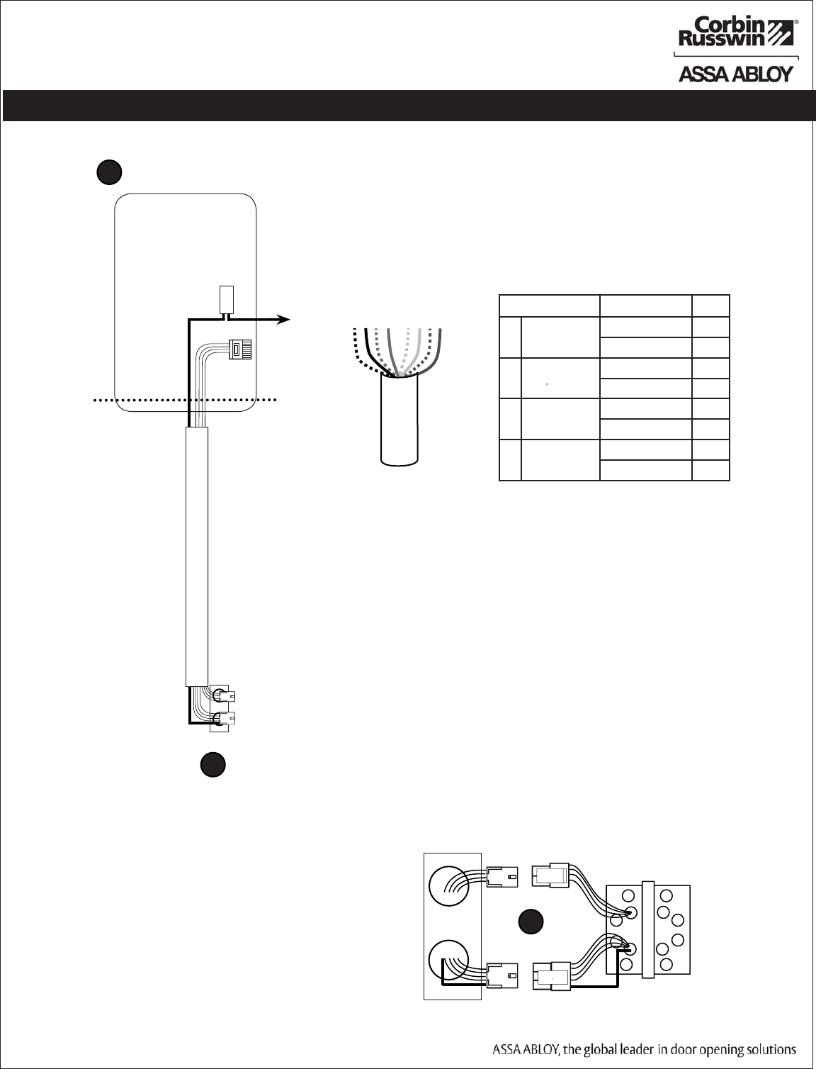
A Frame Harness Installation
Components and wire harness supplied by McKinney: Suggested installation.
RJ45-M
Molex-M
Cable: CAT 5e or higher
24 AWG shielded, 100ohm
B-Splice
Crimp Connector
Ceiling
Supplied by CI
Each of the hinge-side harness connectors should end up threaded
through a different access hole and matched to the same size pin con-
nector from the door harness:
• 4-pin male Molex connector.
• 6-pin male Molex connector with ground wire.
Notes:
• Connectors only go on one way. They cannot be plugged to
incorrect position.
• Do not force and do not offset connectors.
• Be sure they are completely seated (flush).
Cut end / ceiling-side PoE harness:
TIA/EIB-568-B Standard Wiring
1
2
3
4
5
6
7
8
Pair Number Wire PIN
1 White/Blue White/Blue 5
Blue 4
2 White/Orange White/Orange 1
Orange 2
3 White/Green White/Green 3
Green 6
4 White/Brown White/Brown 7
Brown 8
Do not confuse pair numbers with pin numbers. A pair number is
used for reference only (eg: 10BaseT Ethernet uses pairs 2 & 3). The
pin numbers indicate actual physical locations on the plug and jack.
1. Feed cut end of harness into hole on hinge-side through single access
hole.
2. Push one of the connectors back through hole and feed into separate
access hole.
Hinge side of PoE harness:
B
6-pin F
4-pin M
6-pin M
4-pin F
B
Drain Wire
Frame PoE Hinge (Patent Pending)
Frame-Side
Harness
Assembly
(15' length)
24AWG
Stranded
Drain
Wire for
Earth
Ground in
15' Frame
Harness
Cable drain wire
concealed in
shrink tubing
6) PIP (PoE) Installation Wiring (Continued)
Hinge-side harness connectors:
• 4-pin male molex connector
• 6-pin male molex connector with ground wire
Lock-side harness connectors:
• Ring terminal
• (2) 4-pin connectors
PRELIMINARY
ML20700 PWI/PIP Series Mortise Lock
22
Copyright © 2011 Corbin Russwin, Inc., an ASSA ABLOY Group company.
All rights reserved. Reproduction in whole or in part without the
express written permission of Corbin Russwin, Inc. is prohibited.
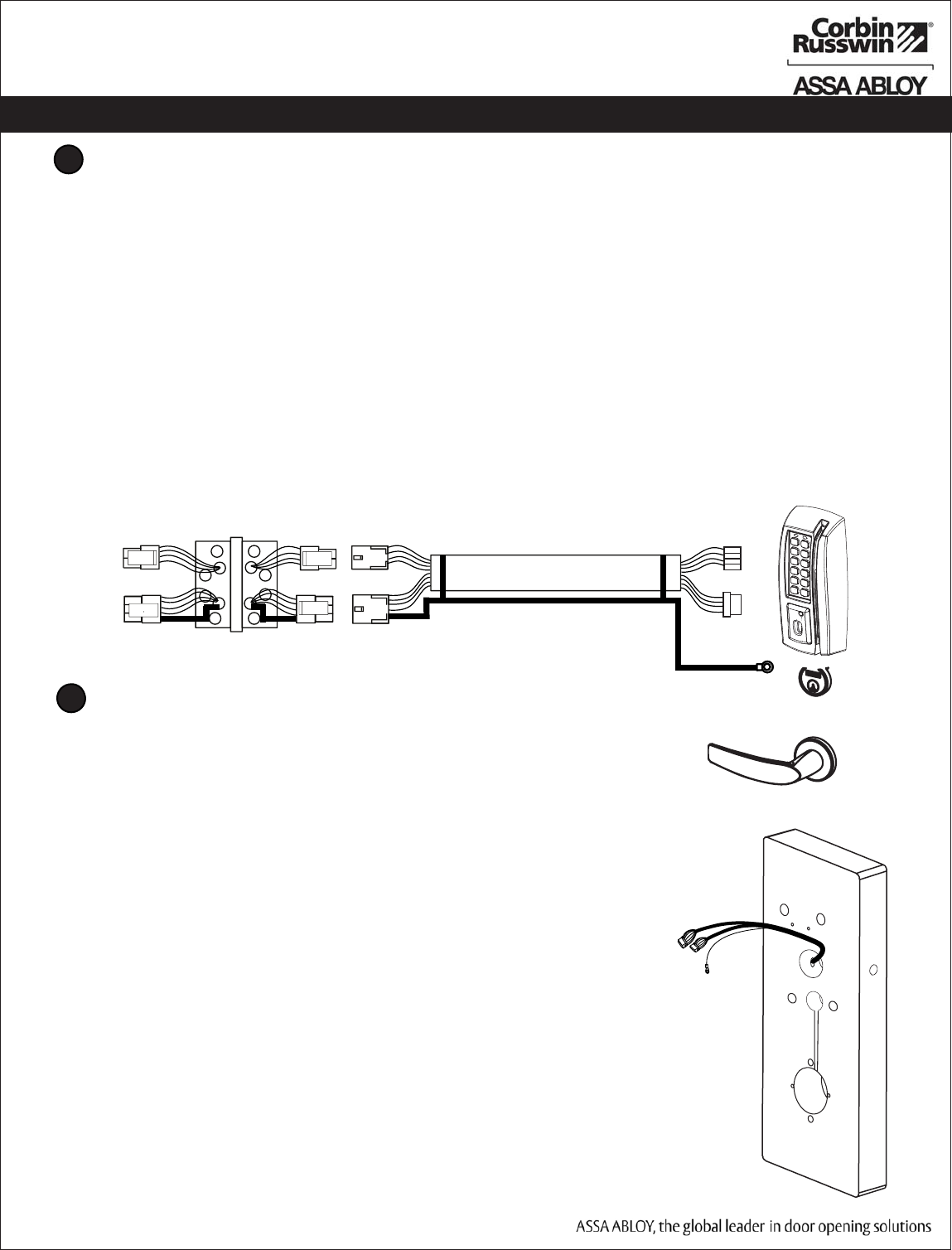
Hinge Installation
Order of installation may vary. Refer to appropriate sections for instructions.
Hinge-side harness connectors:
• 4-pin male Molex connector
• 6-pin male Molex connector with ground wire
Lock-side harness connectors:
• Ring terminal
• (2) 4-pin connectors:
• 4-pin Molex connector
• 4-pin connector
Notes:
• Connectors go on only one way. They cannot be plugged to incorrect position.
• Do not force and do not offset connectors.
• Be sure they are completely seated (flush).
C
Door Harness Installation
Order of installation may vary. Refer to appropriate sections for in-
structions.
1. Prop door open.
2. Tape the two lock-side 4-pin connectors to the ring terminal.
3. Using the ring terminal, carefully fish the assembly through the
door channel to the lock.
4. Remove tape from ring terminal and door harness connectors.
Hinge-side harness connectors:
• 4-pin male Molex connector
• 6-pin male Molex connector with ground wire
Lock-side harness connectors:
• Ring terminal
• (2) 4-pin connectors:
• 4-pin Molex connector
• 4-pin connector
Notes:
• Connectors go on only one way. They cannot be plugged to
incorrect position.
• Do not force and do not offset connectors.
• Be sure they are completely seated (flush).
D
JST
4-Pin
6-pin F 6-pin F 6-pin M
Cable: CAT 5e,
26 AWG stranded,
shielded, 100ohm
4-pin M 4-pin F4-pin F
Drain Wire
PoE Hinge (Patent Pending)
Ring Terminal Secured
to Lock Mounting Plate
Ground
4-Pin
Molex
6) PIP (PoE) Installation Wiring (Continued)
PRELIMINARY
Copyright © 2011 Corbin Russwin, Inc., an ASSA ABLOY Group company.
All rights reserved. Reproduction in whole or in part without the
express written permission of Corbin Russwin, Inc. is prohibited.
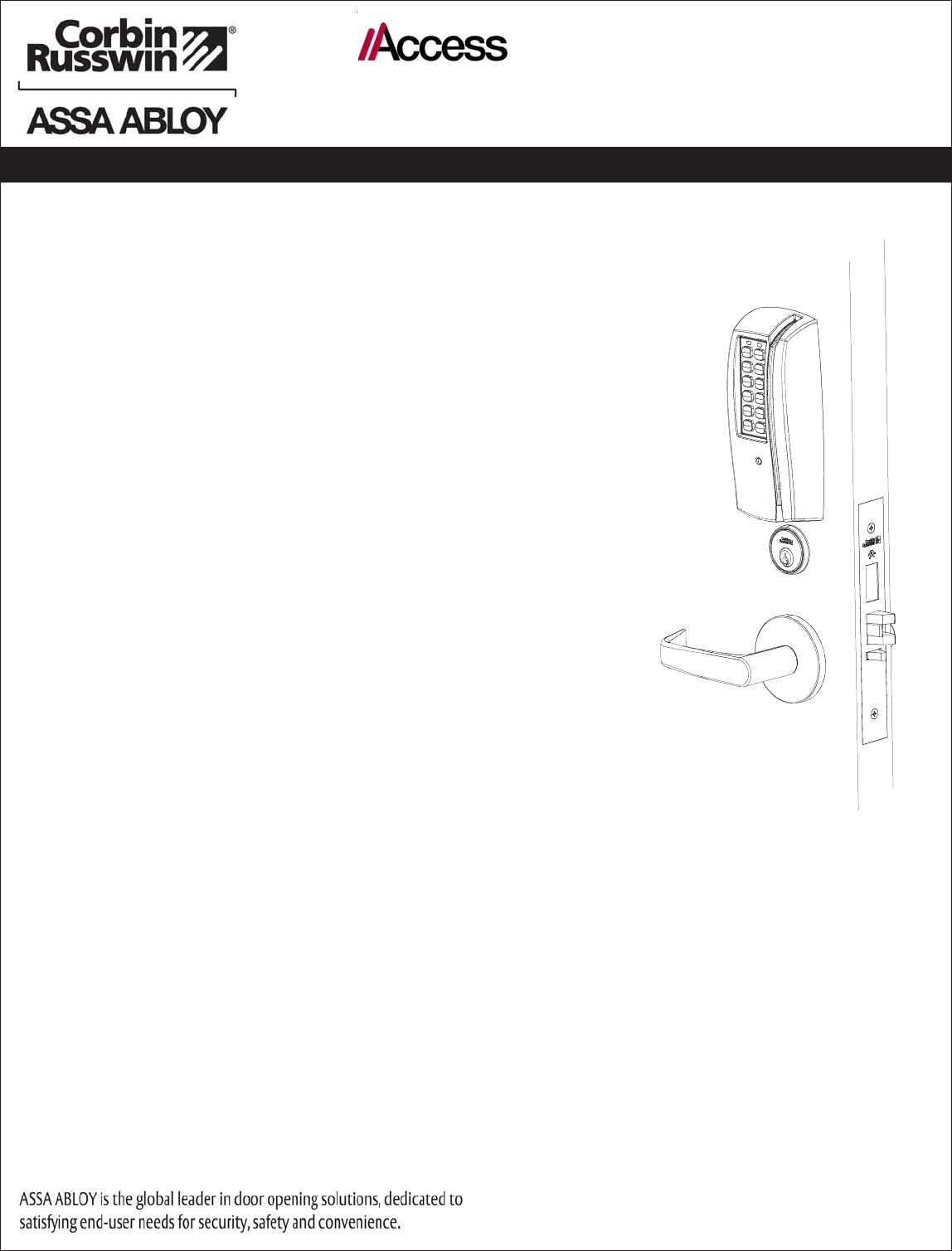
700
™
TCPWI1/TPIP
7) Operational Check
IMPORTANT: Be sure to test functions prior to closing door.
In all cases, perform the following checks:
1. Ensure that inside lever retracts latch (and deadbolt for
deadbolt functions).
• For units with cylinders, the following checks apply:
Insert key into cylinder and rotate
a. There should be no friction against lock case,
wire harness, or any other obstructions. If friction
or binding occurs, readjust cylinder and wiring
harness to eliminate issues.
b. The key should retract the latch and the key
should rotate freely.
c. The key should extend and retract the deadbolt.
• For units without a keypad, add card using LCT
software and test.
• For units with a keypad, add pin and card using LCT
software and test.
2. LED signalling:
• After using a valid credential, a green flash followed
by three fast amber flashes indicates a low power
condition.
Check the input voltage.
If the input voltage is low, disconnect the lock from
the power source and check the power source
voltage. If the power source voltage is correct,
inspect the lock wiring for a possible short.
• If the lock loses power, it will flash rapid amber
for approximately one minute.
After that, the lock will no longer be functional.
3. When you have completed the tests, close the door to
ensure latchbolt and deadbolt fully extend into strike
plate without binding.
PRELIMINARY