ASSALOY SCYMCA1 Aperio V3 iN100 RF Module User Manual FM403 IN100 Mortise Instr

ASSA ABLOY Inc. Aperio V3 iN100 RF Module FM403 IN100 Mortise Instr

User Manual - FM403 IN100 Mortise Instr
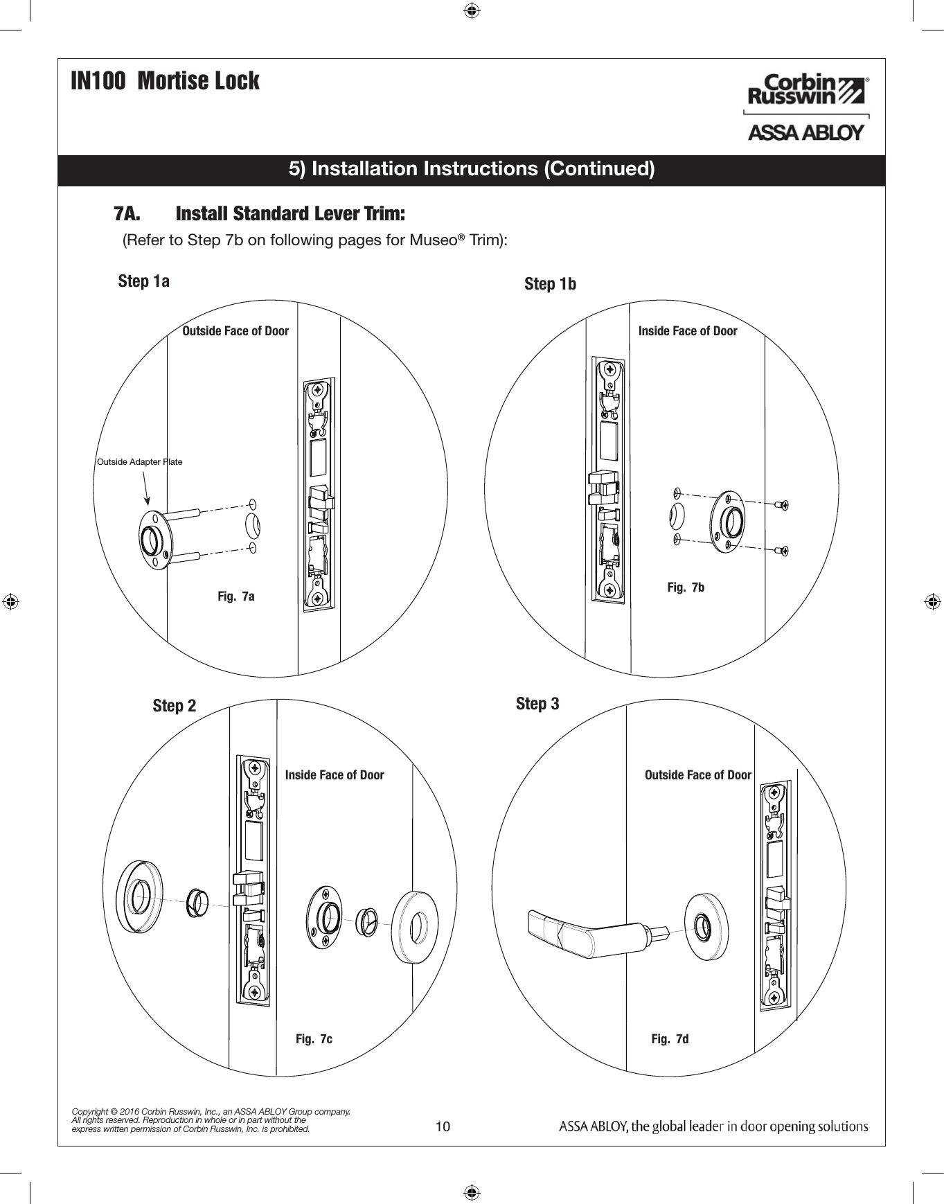
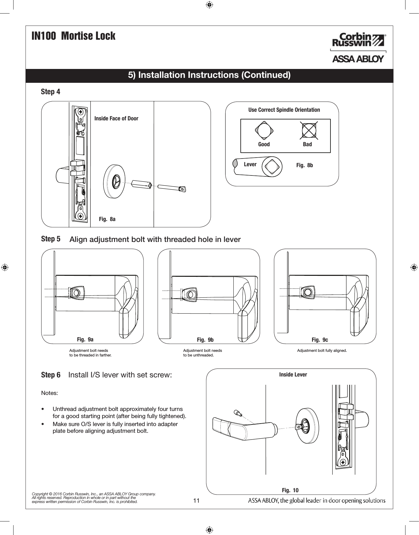
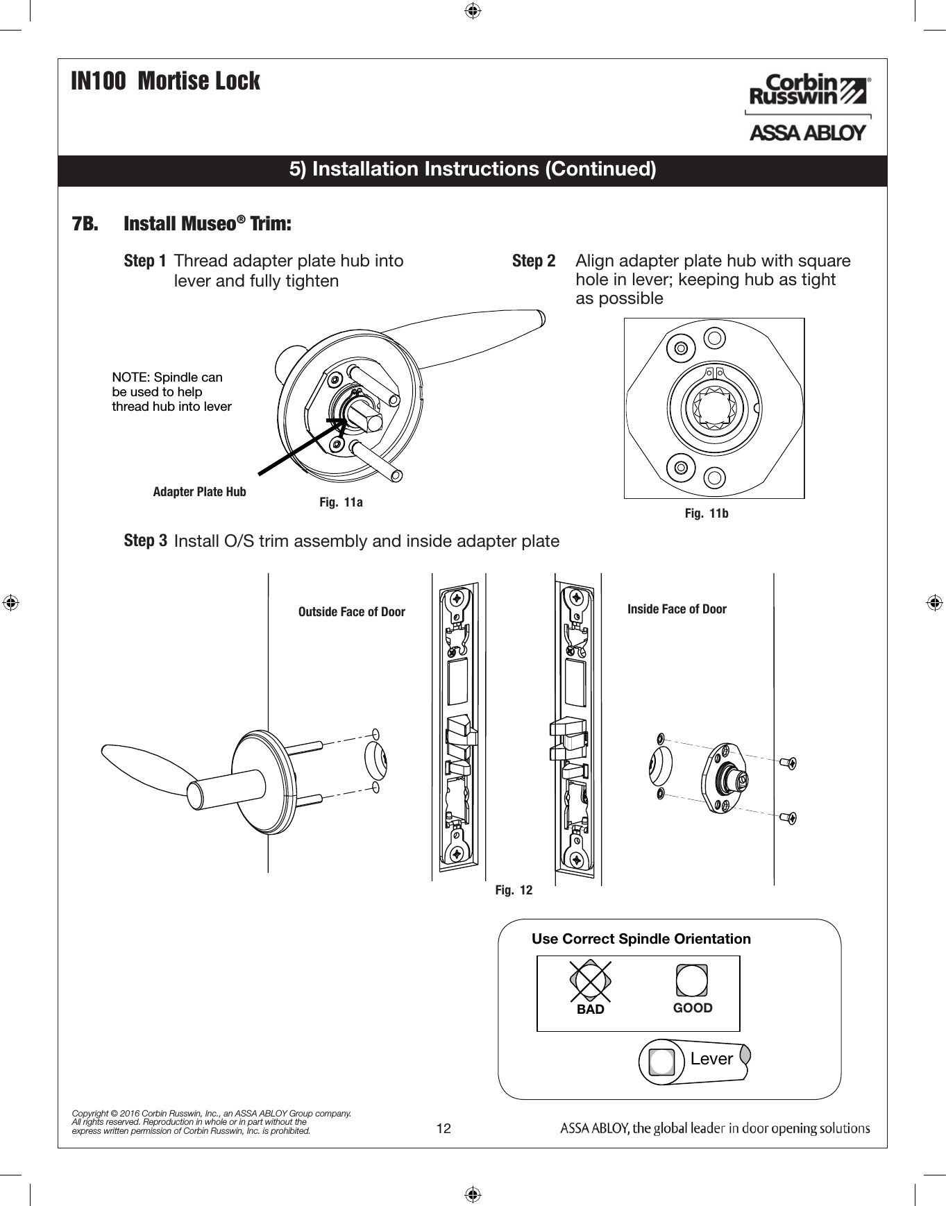
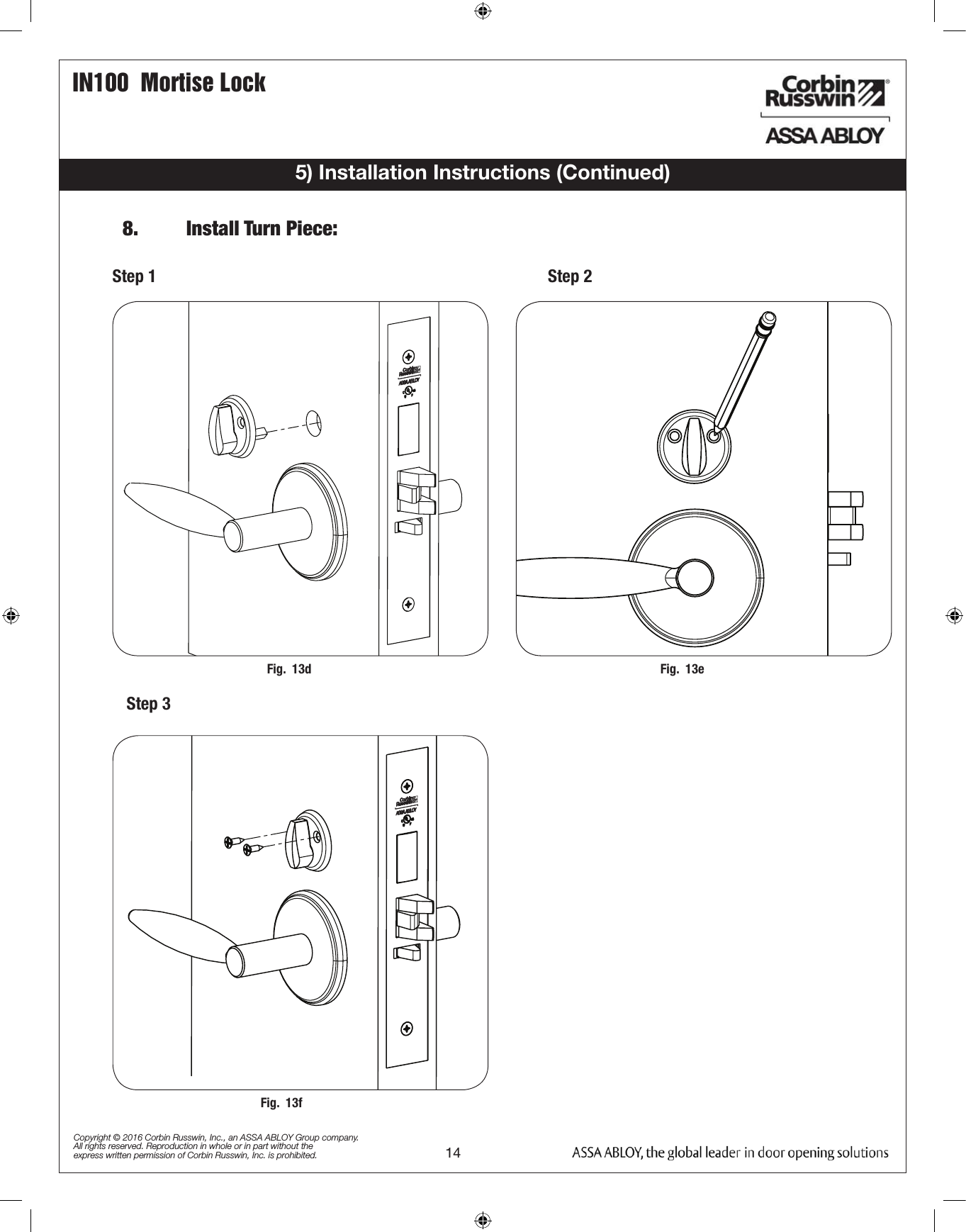
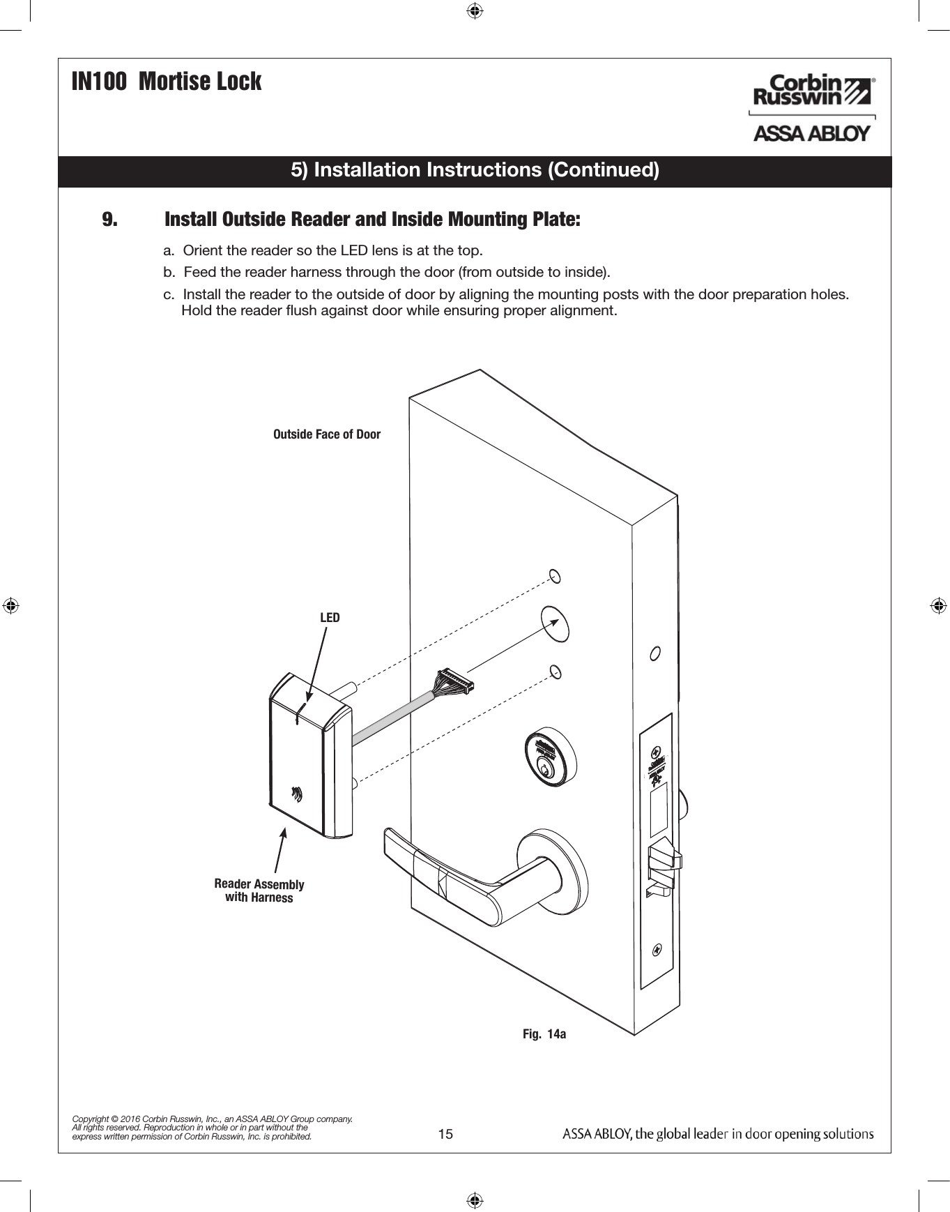
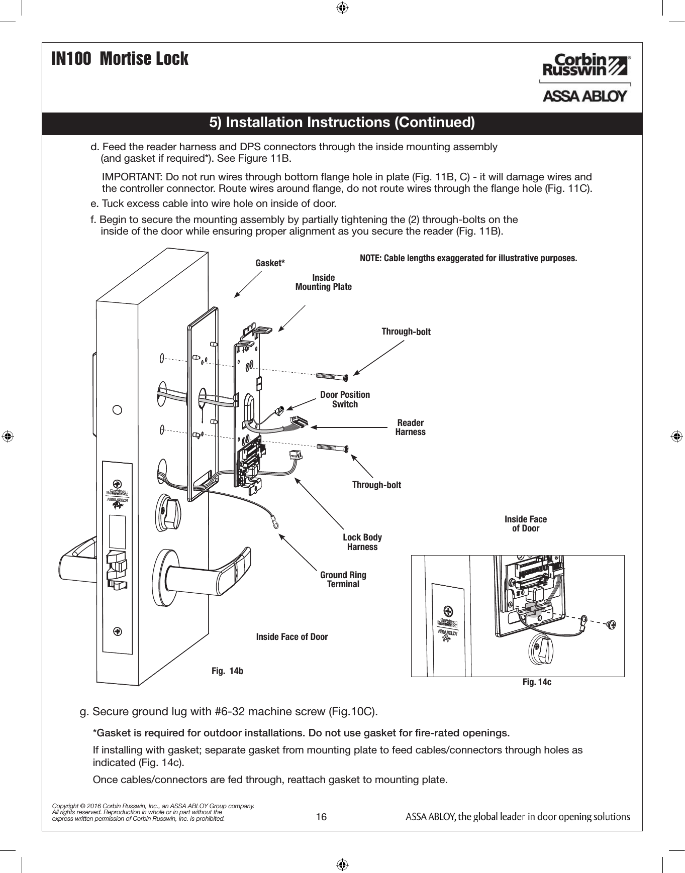
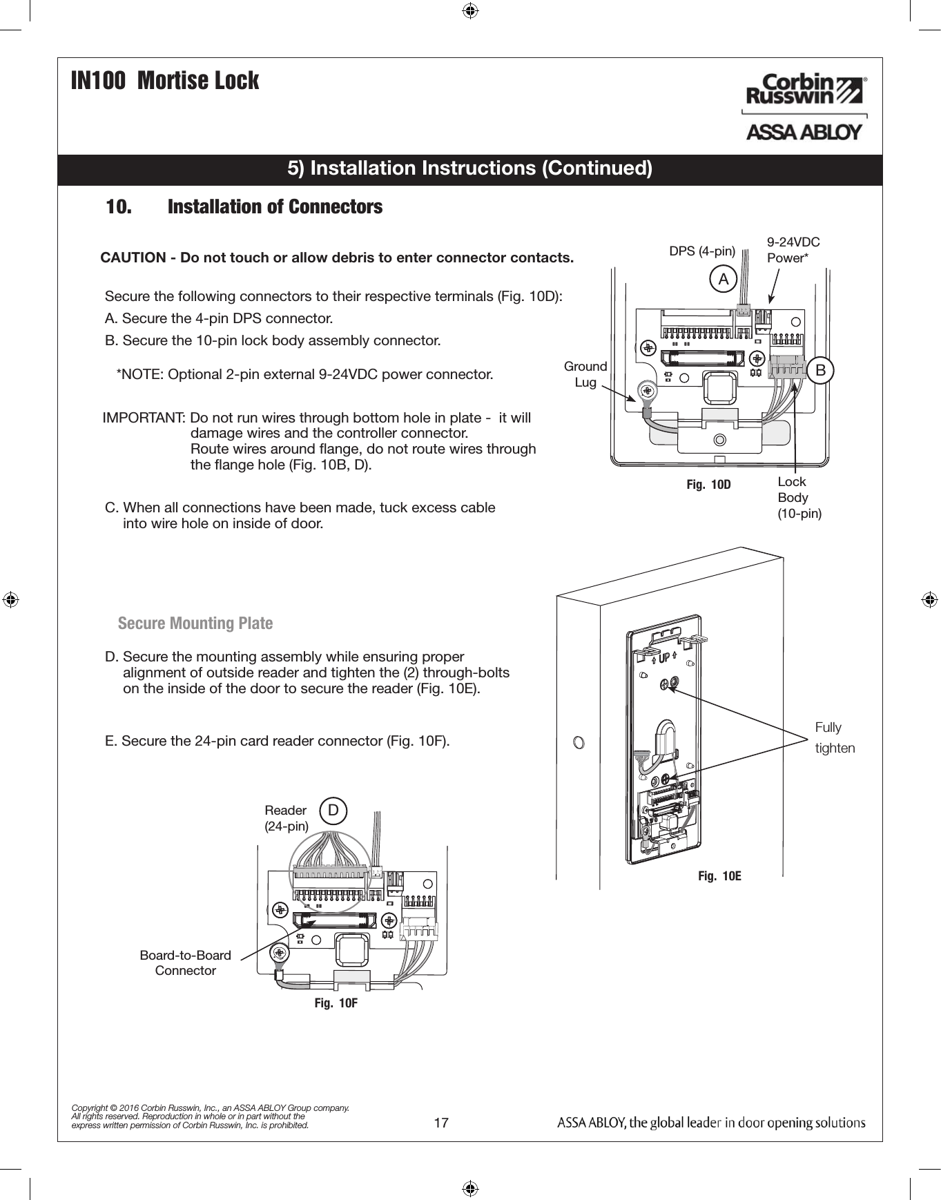
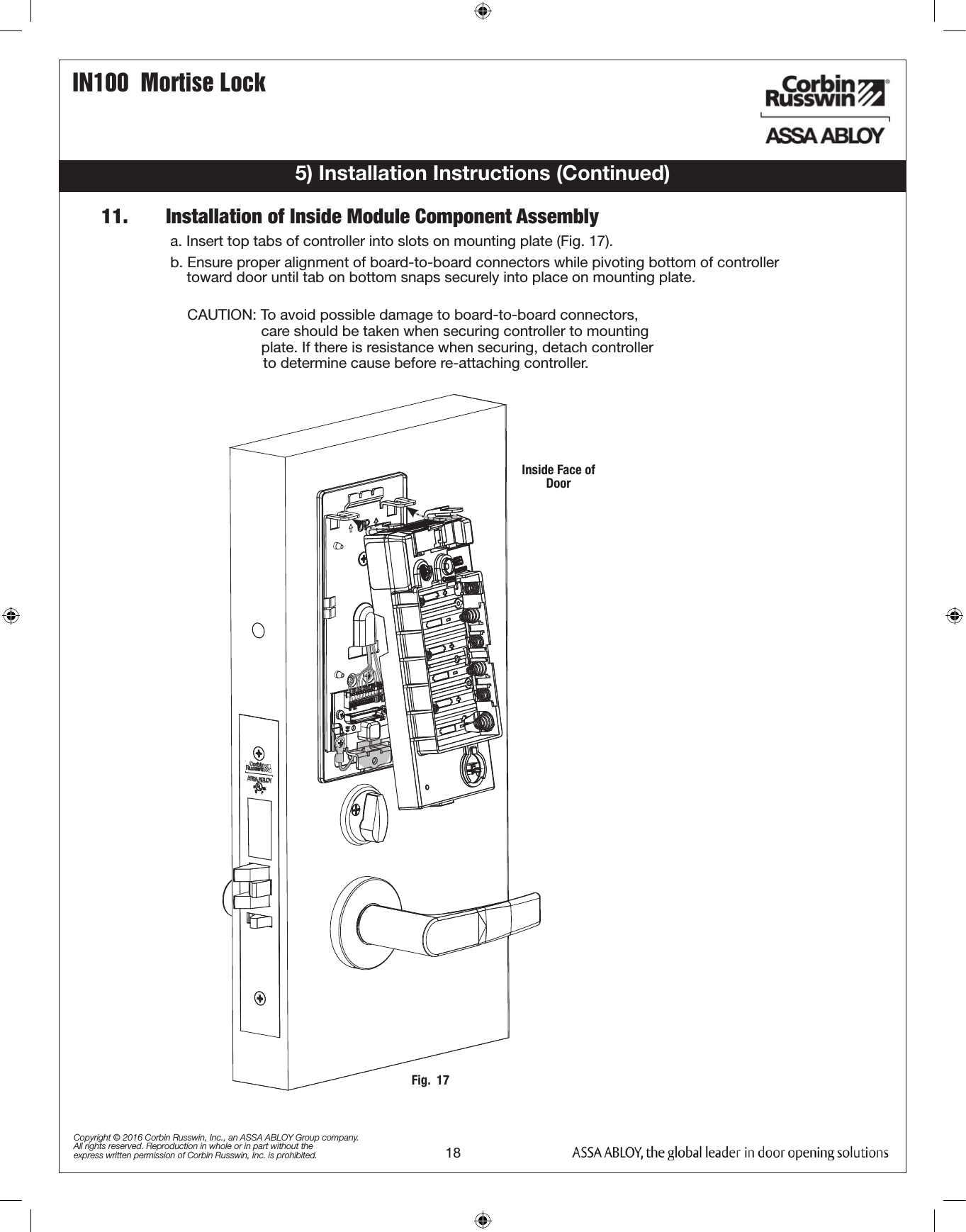
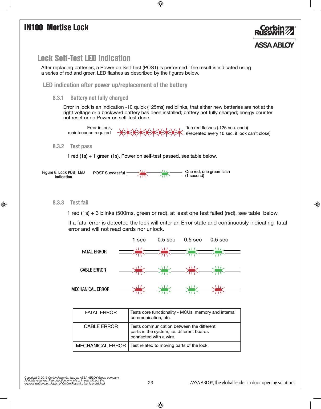
FM403 07/16 Please read these instructions carefully to prevent missing important steps.Please Note: Improper installations may result in damage to the lock and void the factory warranty.Important: The accuracy of the door preparation is critical for proper functioning and security of this lock.                  Misalignment can cause premature wear and a lessening of security.For Technical Assistance call Corbin Russwin at 1-800-810-WIRE (9473)Copyright © 2016 Corbin Russwin, Inc., an ASSA ABLOY Group company. All rights reserved. Reproduction in whole or in part without the express written permission of Corbin Russwin, Inc. is prohibited.Attention InstallerMortise Lockset IN100 WiFi  Installation Instructions
IN100 Mortise Lock1) WarningTable of Contents21) Warning ................................................................................22) General Description .............................................................33) Specifications / Features ....................................................34) Product Illustrations ............................................................45) Installation Instructions ......................................................66) Operational Check .............................................................207) LED Indications .................................................................21!Copyright © 2016 Corbin Russwin, Inc., an ASSA ABLOY Group company. All rights reserved. Reproduction in whole or in part without the express written permission of Corbin Russwin, Inc. is prohibited.This device complies with Part 15 of the FCC Rules. Operation is subject to the following two conditions: (1) this device may not cause harmful interference, and (2) this device must accept any interference received, including interference that may cause undesired operation.Note: This equipment has been tested and found to comply with the limits for a Class B digital device, pursuant to Part 15 of the FCC Rules. These limits are designed to provide reasonable protection against harmful interference in a residential installation.This equipment generates, uses and can radiate radio frequency energy and if not installed and used in accordance with the instructions, may cause harmful interference to radio communications. However, there is no guarantee that the interference will not occur in a particular installation. If this equipment does cause harmful interference to radio or television reception, which can be determined by turning the equip-ment off and on, the user is encouraged to try to correct the interference by one or more of the following measures:• Reorient or relocate the receiving antenna• Increase the separation between the equipment and receiver• Connect the equipment into an outlet on a circuit different from that to which the receiver is connected• Consult the dealer or an experienced technician for helpThe term “IC:” before the radio certification number only signifies that Industry Canada technical specifications were met. This Class B digital apparatus meets all requirements of the Canadian Interference Causing Equipment Regulations. Operation is subject to the following two conditions: (1) this device may not cause harmful interference, and (2) this device must accept any interference received, including interfer-ence that may cause undesired operation. Cet appareillage numérique de la classe B répond à toutes les exigences de l’interférence canadienne causant des règlements d’équipement. L’opération est sujette aux deux conditions suivantes: (1) ce dispositif peut ne pas causer l’interférence nocive, et (2) ce dis-positif doit accepter n’importe quelle interférence reçue, y compris l’interférence qui peut causer l’opération peu désirée.Warning: Changes or modifications to this unit not expressly approved by the party  responsible for compliance could void the user’s authority to operate the equipment.!To comply with “Fire Listed” doors, the batteries must be replaced with alkaline batteries only.!To avoid possible damage from electrostatic discharge (ESD), some basic precautions should be used when handling electronic components:• Minimize build-up of static by touching and/or maintaining contact with unpainted metal surfaces such as door hinges,     latches, and mounting plates especially when mounting electronic components such as readers and controllers onto          the door.• Leave components (reader and controller) protected in their respective anti-static bags until ready for installation• Do not touch pins, leads or solder connections on the circuit boards
IN100  Mortise Lock3Copyright © 2016 Corbin Russwin, Inc., an ASSA ABLOY Group company. All rights reserved. Reproduction in whole or in part without the express written permission of Corbin Russwin, Inc. is prohibited.To comply with “Fire Listed” doors, the batteries must be replaced with alkaline batteries only.• Latch – Stainless Steel (Easily field reversible       without disassembling lock body)• Deadbolt – Stainless Steel• Auxiliary Latch – Stainless steel, non-handed• Door Thickness – 1-3/4” Standard; can be    furnished for other door thicknesses upon    request. Consult factory.• Case – 12 gauge heavy duty wrought steel2) General Description3) Specifications / FeaturesThe Corbin Russwin® IN100 mortise lock with Aperio™ Technology makes it easy and cost-effective to bring access control to more doors. It uses local wireless communication between the lock and an Aperio hub to connect to an access control system, eliminating the greatest cost and inconvenience of traditional access control – the wiring at the door. The IN100 utilizes HID® 125 kHz prox or 13.56 MHz iCLASS® smart card  technology, and all technology features are supported by the physical security of Corbin Russwin            ANSI/BHMA Grade 1 hardware.This product is operated by six (6) “AA” alkaline batteries. Corbin Russwin mortise locks are designed with quality components to provide high security, performance and durability.Electronic Specifications**For specific security information, please contact your local ASSA ABLOY Door Security Solutions sales consultant or call 800-810-WIRE.•  Input Power: DC 9V, 1.5A (6 AA alkaline batteries)•  Optional hard-power 12VDC to 24VDC•  HID® multiCLASS SE® technology offers support for the following credentials:•  High Frequency (13.56 MHz):•  HID iCLASS®•  HID iCLASS SE® (SIO-enabled)•  HID iCLASS® Seos™•  HID MIFARE® SE•  HID DESfire® EV1 SE•  MIFARE Classic•  DESfire EV1•  Low Frequency (125 kHz):•  HID Prox® •  NFC-enabled Mobile Phones•  Uses low-rate wireless personal area networks (IEEE 802.14.4)•  Multiple time zone and holiday access scheduling•  First-in unlock or automatic unlock configuration, based on specified time schedule•  Uses AES 128-bit wireless encryption**•  Privacy button• Outside lever controlled by reader or key      retracts latch• Inside Lever produces REX (request to exit) signal        and retracts latch and deadbolt*• UL fire listed• May be used for both indoor and exterior applications• A weather-protective gasket is required for     exterior applications Hardware Specifications
IN100  Mortise Lock4Copyright © 2016 Corbin Russwin, Inc., an ASSA ABLOY Group company. All rights reserved. Reproduction in whole or in part without the express written permission of Corbin Russwin, Inc. is prohibited.4) Product Illustrations** Specify finishITEM PART NUMBER/ORDER STRING DESCRIPTION COLOR/TRIM QTY1 IN-100-EM01[locktype]*-IP-B HID iCLASS®, HID iCLASS SE® (SIO-enabled), HID iCLASS® Seos™, HID MIFARE® SE, HID DESfire® EV1 SE, HID Prox®, NFC-enabled mobile phones Black 1IN-100-EM01[locktype]*-IP-W HID iCLASS®, HID iCLASS SE® (SIO-enabled), HID iCLASS® Seos™, HID MIFARE® SE, HID DESfire® EV1 SE, HID Prox®, NFC-enabled mobile phonesWhite 1IN-100-EM01[locktype]*-IP-MB-[finish]** HID iCLASS®, HID iCLASS SE® (SIO-enabled), HID iCLASS® Seos™, HID MIFARE® SE, HID DESfire® EV1 SE, HID Prox®, NFC-enabled mobile phonesBlack with metal trim 1IN-100-EM01[locktype]*-IP-MW-[finish]** HID iCLASS®, HID iCLASS SE® (SIO-enabled), HID iCLASS® Seos™, HID MIFARE® SE, HID DESfire® EV1 SE, HID Prox®, NFC-enabled mobile phonesWhite with metal trim 1IN-100-EM01[locktype]*-IPS-B All credentials supported by the IP option plus MIFARE Classic and DESfire EV1 Black 1IN-100-EM01[locktype]*-IPS-W All credentials supported by the IP option plus MIFARE Classic and DESfire EV1 White 1IN-100-EM01[locktype]-IPS-MB-[finish]** All credentials supported by the IP option plus MIFARE Classic and DESfire EV1 Black with metal trim 1IN-100-EM01[locktype]-IPS-MW-[finish]** All credentials supported by the IP option plus MIFARE Classic and DESfire EV1 White with metal trim 12 782F718 Inside Mounting Kit (mounting plate & hardware) 13 N/A AA battery 64 820F489 Inside Escutcheon Black 1820F499 Inside Escutcheon White820F525 FIN* Inside Escutcheon Black with metal trim820F535 FIN* Inside Escutcheon White with metal trim5 FM355 Field prep template (not shown) 16 T31202 Door manufacturers template (not shown) 1-- FM403 Instructions (this manual) 115412* ML20133/36 (example: IN-100-EM01ML20136-IP-B)
IN100  Mortise Lock5Copyright © 2016 Corbin Russwin, Inc., an ASSA ABLOY Group company. All rights reserved. Reproduction in whole or in part without the express written permission of Corbin Russwin, Inc. is prohibited.Tools Required:• Phillips Screw Driver #2, #3• Flat Blade Screw Driver (Standard size)• 1/8” Security Allen Wrench (supplied• 7/64” Allen Wrench (supplied)4) Product Illustrations (Continued)1 784F848[handing]*26D ML20133/ML20134 Lock Case (No Deadbolt)** 1784F858[handing]*26D ML20135/ML20136 Lock Case (With Deadbolt)**2 783F619 DPS (Door Position Switch) Kit 1*Replace with handing (L, LR, R, RR)1*2For parts not listed, refer to ML2000 Parts and Service Manual**Escape return functionality is not available with the IN100 ML201xx mortise lock.820F609
IN100  Mortise Lock6Copyright © 2016 Corbin Russwin, Inc., an ASSA ABLOY Group company. All rights reserved. Reproduction in whole or in part without the express written permission of Corbin Russwin, Inc. is prohibited.5) Installation InstructionsLeft HandHinges Left.Open Inward.“LH”Left HandReverse BevelHinges Left.Open Outward“LHRB”Right HandHinges Right.Open Inward.“RH”Right HandReverse BevelHinges Right.Open Outward“RHRB”Illustrations shown are as viewed from the outside or secure side of opening.2.   Door PreparationOutside Face of DoorInside Face of Door1.   Verify Hand and Bevel of doorPrep door according to supplied door marker (FM355). For door manufacturer templates  visit www.corbinrusswin.com and reference template # T31202.Fig.  1Fig.  2Through-bolt HoleOutside Cylinder Hole(only with cylinder installation)Lever Handle HoleExternal DPS HoleCable Hole Through-bolt HoleInside of Lock body Wire HoleThumb Turn Lever HoleLever Handle HoleLever Post HolesMortisePocketRaceway for Optional Remote Power Raceway for Optional Remote PowerWood Door shown
IN100  Mortise Lock7Copyright © 2016 Corbin Russwin, Inc., an ASSA ABLOY Group company. All rights reserved. Reproduction in whole or in part without the express written permission of Corbin Russwin, Inc. is prohibited.Illustrations shown are as viewed from the outside or secure side of opening.a.  Push wires through raceway toward lock prep.b.  Push DPS firmly into place by hand.      Note: DO NOT TAP SWITCH WITH ANY TOOL.c.  Install magnet into door frame. Push firmly into place by hand.       See instruction A7983. 3.   Install Door Position Switch (DPS)CAUTION: if DPS is not installed or is installed improperly, door status monitoring features will not function.5) Installation Instructions (Continued)Collar is used onlywith metal doors Door Status Switch Inside of DoorFig. 3*Only required on the ML201xx lock body (ML202xx has an integrated DPS)
IN100  Mortise Lock8Copyright © 2016 Corbin Russwin, Inc., an ASSA ABLOY Group company. All rights reserved. Reproduction in whole or in part without the express written permission of Corbin Russwin, Inc. is prohibited.RED Locking Screw  d. Push in latch while holding  screw driver      behind latch tail (Fig. 3)      Note:  Push in latch until catch plate is no                   longer depressed (Fig. 4) e.  Rotate lock front to match  bevel of door       as shown (Fig. 5)  Catch Plate  MAKE SURE CATCH PLATE IS  EVEN W/ TOP SURFACE  WARNING:   LOCK-IN CAN    OCCUR IF LATCH  IS NOT PROPERLY  INSTALLED  5) Installation Instructions (Continued)4.   Lock Handing Instructionsa.  Move the Red locking screw to  side of lock-body               being locked (Fig. 4a) b.  Push in latch then depress catch  plate with screw              driver (Fig. 4a) c. Pull latch out of lock-body  and turn latch over (Fig. 4b)  Fig. 4aFig. 4bFig. 4dFig. 4cFig. 4e
IN100  Mortise Lock9Copyright © 2016 Corbin Russwin, Inc., an ASSA ABLOY Group company. All rights reserved. Reproduction in whole or in part without the express written permission of Corbin Russwin, Inc. is prohibited.5) Installation Instructions (Continued)a. Feed wires through 1-5/16” diameter hole on INSIDE of door while installing lock body (Fig. 5a).b. Pull wires through hole while inserting lock body. DO NOT push wires back into cylinder hole (Fig. 5b).Important: Door must remain open during installation. Use door stop. c. Install, but do not tighten two #12 x 1” combination screws through lock body (Fig. 5a). Fig.  5aFig.  5bOutside Face of Door(2) #12 x 1” Do not tightenInside Face of DoorFrom Lock Body6.         Install Cylinder:Position cylinder so that the logo is right-side up.Correct           IncorrectFig. 6a1Fig. 6a Fig.  6b7/64" Allen WrenchDPS5.   Install Lock Body in Door:a. Slide cylinder through collar. Thread cylinder into lock body (Fig. 6a).Note: Make sure cylinder is oriented correctly (Fig. 6a1).b. Tighten cylinder clamp using 7/64” allen wrench (Fig. 6b). c. Turn the key to make sure that lock functions correctly  (latch, deadbolt, and key).
IN100  Mortise Lock10Copyright © 2016 Corbin Russwin, Inc., an ASSA ABLOY Group company. All rights reserved. Reproduction in whole or in part without the express written permission of Corbin Russwin, Inc. is prohibited.7A.   Install Standard Lever Trim:   (Refer to Step 7b on following pages for Museo® Trim): Step 2  Step 3 Fig.  7cInside Face of DoorFig.  7aInside Face of DoorFig.  7bOutside Face of DoorOutside Adapter PlateFig.  7dOutside Face of DoorStep 1a  Step 1b 5) Installation Instructions (Continued)
IN100  Mortise Lock11Copyright © 2016 Corbin Russwin, Inc., an ASSA ABLOY Group company. All rights reserved. Reproduction in whole or in part without the express written permission of Corbin Russwin, Inc. is prohibited.Fig.  8aInside Face of DoorStep 4 Step 5  Align adjustment bolt with threaded hole in leverAdjustment bolt needsto be threaded in farther.Adjustment bolt needsto be unthreaded.Adjustment bolt fully aligned. Notes:•  Unthread adjustment bolt approximately four turns  for a good starting point (after being fully tightened).•  Make sure O/S lever is fully inserted into adapter plate before aligning adjustment bolt.STANDARD MUSÉOkƒ„ƒ·Use Correct Spindle OrientationGood                                                Bad                           Lever           Fig.  8b5) Installation Instructions (Continued)Inside LeverFig.  9a Fig.  9b Fig.  9cFig.  10Step 6   Install I/S lever with set screw:
IN100  Mortise Lock12Copyright © 2016 Corbin Russwin, Inc., an ASSA ABLOY Group company. All rights reserved. Reproduction in whole or in part without the express written permission of Corbin Russwin, Inc. is prohibited.NOTE: Spindle can be used to help thread hub into lever  Adapter Plate Hub  Step 1   Thread adapter plate hub into  lever and fully tighten Step 2Install O/S trim assembly and inside adapter plate Step 37B.   Install Museo® Trim:5) Installation Instructions (Continued)Use Correct Spindle Orientation  BAD GOOD  Lever  Outside Face of DoorAlign adapter plate hub with square  hole in lever; keeping hub as tight      as possible  Inside Face of DoorFig.  11a Fig.  11bFig.  12
IN100  Mortise Lock13Copyright © 2016 Corbin Russwin, Inc., an ASSA ABLOY Group company. All rights reserved. Reproduction in whole or in part without the express written permission of Corbin Russwin, Inc. is prohibited.5) Installation Instructions (Continued)   Install Armored Front:a. Tighten (2) screws through lock body.b. Attach armored front with two #8 x ¼” screws (Fig. 13c).   Install Spindle and Rose:a. Align studs on rose with bushings in adapter plate.   Install I/S lever with set screw:Step 4Step 5Step 6Outside Face of DoorFig.  13aFig.  13bFig.  13c
IN100  Mortise Lock14Copyright © 2016 Corbin Russwin, Inc., an ASSA ABLOY Group company. All rights reserved. Reproduction in whole or in part without the express written permission of Corbin Russwin, Inc. is prohibited.5) Installation Instructions (Continued)Step 18.   Install Turn Piece:Step 2Step 3Fig.  13d Fig.  13eFig.  13f
IN100  Mortise Lock15Copyright © 2016 Corbin Russwin, Inc., an ASSA ABLOY Group company. All rights reserved. Reproduction in whole or in part without the express written permission of Corbin Russwin, Inc. is prohibited.9.   Install Outside Reader and Inside Mounting Plate:Fig.  14aOutside Face of DoorReader Assembly with HarnessLED5) Installation Instructions (Continued)a.  Orient the reader so the LED lens is at the top.b.  Feed the reader harness through the door (from outside to inside).c.  Install the reader to the outside of door by aligning the mounting posts with the door preparation holes.                 Hold the reader flush against door while ensuring proper alignment.
IN100  Mortise Lock16Copyright © 2016 Corbin Russwin, Inc., an ASSA ABLOY Group company. All rights reserved. Reproduction in whole or in part without the express written permission of Corbin Russwin, Inc. is prohibited.5) Installation Instructions (Continued)Fig.  14bGround Ring TerminalLock Body          HarnessThrough-boltReader HarnessThrough-boltInside        Mounting Plate Gasket*Door Position Switch*Gasket is required for outdoor installations. Do not use gasket for fire-rated openings. If installing with gasket; separate gasket from mounting plate to feed cables/connectors through holes as indicated (Fig. 14c). Once cables/connectors are fed through, reattach gasket to mounting plate.NOTE: Cable lengths exaggerated for illustrative purposes.Inside Face of DoorInside Face of DoorFig. 14cg. Secure ground lug with #6-32 machine screw (Fig.10C).d. Feed the reader harness and DPS connectors through the inside mounting assembly                                              (and gasket if required*). See Figure 11B.IMPORTANT: Do not run wires through bottom flange hole in plate (Fig. 11B, C) - it will damage wires and the controller connector. Route wires around flange, do not route wires through the flange hole (Fig. 11C).e. Tuck excess cable into wire hole on inside of door.f. Begin to secure the mounting assembly by partially tightening the (2) through-bolts on the            inside of the door while ensuring proper alignment as you secure the reader (Fig. 11B).
IN100  Mortise Lock17Copyright © 2016 Corbin Russwin, Inc., an ASSA ABLOY Group company. All rights reserved. Reproduction in whole or in part without the express written permission of Corbin Russwin, Inc. is prohibited.5) Installation Instructions (Continued)Secure the following connectors to their respective terminals (Fig. 10D):A. Secure the 4-pin DPS connector.B. Secure the 10-pin lock body assembly connector.CAUTION - Do not touch or allow debris to enter connector contacts. IMPORTANT: Do not run wires through bottom hole in plate -  it will                       damage wires and the controller connector.                        Route wires around flange, do not route wires through                        the flange hole (Fig. 10B, D).E. Secure the 24-pin card reader connector (Fig. 10F).Ground  LugDPS (4-pin)ALock Body (10-pin)Fig.  10DBReader (24-pin)Board-to-Board ConnectorFig.  10FDD. Secure the mounting assembly while ensuring proper             alignment of outside reader and tighten the (2) through-bolts            on the inside of the door to secure the reader (Fig. 10E).Secure Mounting Plate*NOTE: Optional 2-pin external 9-24VDC power connector.9-24VDC Power*C. When all connections have been made, tuck excess cable             into wire hole on inside of door.Fig.  10EFully tighten10.   Installation of Connectors
IN100  Mortise Lock18Copyright © 2016 Corbin Russwin, Inc., an ASSA ABLOY Group company. All rights reserved. Reproduction in whole or in part without the express written permission of Corbin Russwin, Inc. is prohibited.5) Installation Instructions (Continued)11.       Installation of Inside Module Component Assemblya. Insert top tabs of controller into slots on mounting plate (Fig. 17).b. Ensure proper alignment of board-to-board connectors while pivoting bottom of controller            toward door until tab on bottom snaps securely into place on mounting plate.  CAUTION: To avoid possible damage to board-to-board connectors,                    care should be taken when securing controller to mounting                    plate. If there is resistance when securing, detach controller                  to determine cause before re-attaching controller.Fig.  17Inside Face of Door
IN100  Mortise Lock19Copyright © 2016 Corbin Russwin, Inc., an ASSA ABLOY Group company. All rights reserved. Reproduction in whole or in part without the express written permission of Corbin Russwin, Inc. is prohibited.Fig.  195) Installation Instructions (Continued)a. Assemble cover by hooking top edge on inside          mounting plate.b. Carefully press bottom of cover toward door with      out pinching or damaging any wires.c. Fully secure cover by tightening the security screw      at bottom of cover (Fig.19), utilizing a security           allen wrench.12.       Installing Batteries13.       Inside Cover InstallationFig.  18a.  Place (6) “AA” alkaline batteries in the compartment, being            careful to align polarity properly (Fig. 18).b.  After batteries are installed, there is a slight delay; then red and       green flash, audible “beep” and lock motor will cycle.
IN100  Mortise Lock20Copyright © 2016 Corbin Russwin, Inc., an ASSA ABLOY Group company. All rights reserved. Reproduction in whole or in part without the express written permission of Corbin Russwin, Inc. is prohibited.6) Operational CheckNote: The credential should approach the inscription             on the reader as indicated (Fig. 20b) to ensure                         that the credential is read properly.       Do not wave credential. Fig.  20aFig.  20bWhen lock is fully installed, perform the following steps:a. Insert key into cylinder and rotate (Fig. 20a). b. There should be no friction against lock case, wire harness or          any other obstructions.c. Check that the key retracts the latch.d. The key should rotate freely.e. Try the inside lever; ensure it retracts latch.f.  Present a valid credential* (Fig. 20b) to unlock outside lever; turn       lever handle to ensure latch retracts.
IN100  Mortise Lock21Copyright © 2016 Corbin Russwin, Inc., an ASSA ABLOY Group company. All rights reserved. Reproduction in whole or in part without the express written permission of Corbin Russwin, Inc. is prohibited.Communication Hub LED indications  The communication hub has a single LED. It  supports an optical scheme of red, green and  yellow. The indication scheme is described by  the figures below:  Figure 1. Communication hub normal        operation LED indication2  sec.  Online   Green  Aperio®  lock   Green + one red flash  offline  EAC  offline  Aperio® lock and   Green + three red flashes  EAC  offline  UHF   Yellow + off, fast flash  communication  Some special LED indication schemes* are used during lock maintenance actions:  2  sec.  Figure 2. Communication hub maintenance    LED indication   Pairing  active   Yellow + green  Ethernet LED indication  The LED on the AH40 communication hub*  indicates both the status of the Ethernet link  level and ethernet communication:  2  sec.  Figure 3. AH40 Communication hub                 Ethernet LED indication   Ethernet link  connected   Green  Ethernet Green  +   communication off fast flash  Green + two red flashes  7) LED Indications*For more information, refer to Aperio Online Quick Installation Guide (Document No: ST-001322-PF Date: 2015-12-23)
IN100  Mortise Lock22Copyright © 2016 Corbin Russwin, Inc., an ASSA ABLOY Group company. All rights reserved. Reproduction in whole or in part without the express written permission of Corbin Russwin, Inc. is prohibited.1)  Lock LED indications  The lock has three LEDs. They support an optical  scheme with red, yellow and green. The  indication scheme is described by the figures  below:  Figure 4. Lock normal  operation LED indication  One yellow flash after card, two flashes before PIN (.125 second)   Card + PIN access (configurable)  Access granted,   One green flash (1 sec.)  EAC offline or online  Access denied,   One red flash (1 sec.)  EAC online  Force closed in remote   Five yellow flashes and  open/office mode   one red flash (.25 second)  Busy blink, com hub busy with other locks  Continuous yellow flashes (.25 seconds every second)  Access denied,   Three red flashes (.5 second each)  EAC offline  Lock mechanism is   Continuous red flashes  blocked when closing  (.125 seconds every 1 sec.)  Error in lock,   Ten red flashes (.125 sec. each)  maintenance required (Repeated every 10 sec. if lock can’t close)  Ten red flashes (.125 sec. each) repeated every 10 sec.  Tamper  Time to replace   Continuous yellow flashes (.25 seconds every 5 sec.)  the battery  Battery reached end of life, lock disabled  Continuous red flashes (.25 seconds every 5 sec.)  1) When the lock mechanism is blocked (lock jammed) the lever must be turned to       release the lock mechanism.  Some special LED indication schemes are used during lock maintenance actions:  Figure 5. Lock hub  normal operation LED  indication   Enter  configuration   Five yellow flashes  (.125 second each)  mode  One yellow flash (.25 second)   Card access (configurable)  Enter PIN  EAC response time V3 USB cable detection action  occurred  Five yellow flashes  (.25 second each)
IN100  Mortise Lock23Copyright © 2016 Corbin Russwin, Inc., an ASSA ABLOY Group company. All rights reserved. Reproduction in whole or in part without the express written permission of Corbin Russwin, Inc. is prohibited.Lock Self-Test LED indication  After replacing batteries, a Power on Self Test (POST) is performed. The result is indicated using a series of red and green LED flashes as described by the figures below. 8.3.1   Battery not fully charged   8.3.2   Test pass   1 red (1s) + 1 green (1s), Power on self-test passed, see table below.  Error in lock,   Ten red flashes (.125 sec. each)  maintenance required (Repeated every 10 sec. if lock can’t close)  LED indication after power up/replacement of the battery Figure 6. Lock POST LED  indication  8.3.3   Test fail   1 red (1s) + 3 blinks (500ms, green or red), at least one test failed (red), see table  below.    FATAL ERRORCABLE ERRORMECHANICAL ERRORFATAL ERROR Tests core functionality - MCUs, memory and internal communication, etc.CABLE ERROR Tests communication between the different  parts in the system, i.e. different boards  connected with a wire.  MECHANICAL ERROR Test related to moving parts of the lock.1 sec 0.5 sec 0.5 sec 0.5 secOne red, one green flash  POST  Successful   (1 second)  If a fatal error is detected the lock will enter an Error state and continuously indicating  fatal error and will not read cards nor unlock. Error in lock is an indication -10 quick (125ms) red blinks, that either new batteries are not at the right voltage or a backward battery has been installed; battery not fully charged; energy counter not reset or no Power on self-test done.
Copyright © 2016 Corbin Russwin, Inc., an ASSA ABLOY Group company. All rights reserved. Reproduction in whole or in part without the express written permission of Corbin Russwin, Inc. is prohibited.

Navigation menu