ASSALOY SCYMCA1 Aperio V3 iN100 RF Module User Manual A8190B IN100 V3 Mortise
ASSA ABLOY Inc. Aperio V3 iN100 RF Module A8190B IN100 V3 Mortise
ASSALOY >
Contents
- 1. User Manual - A8190B IN100 (V3) Bored
- 2. User Manual - A8190B IN100 (V3) Mortise
- 3. User Manual - FM403 IN100 Mortise Instr
- 4. User Manual - FM404 IN100 Bored Instr
- 5. MANUAL
- 6. MANUAL - MODULE INTEGRATION
User Manual - A8190B IN100 (V3) Mortise

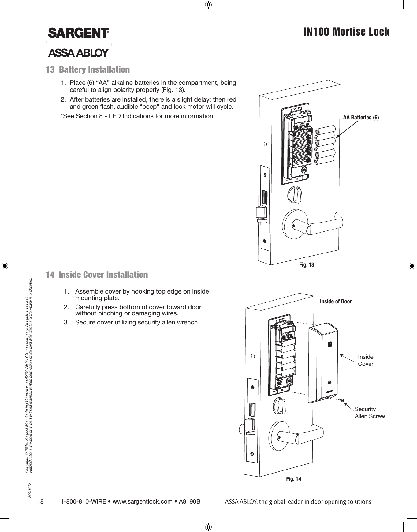
![4 1-800-810-WIRE • www.sargentlock.com • A8190B Copyright © 2016, Sargent Manufacturing Company, an ASSA ABLOY Group company. All rights reserved. Reproductions in whole or in part without express written permission of Sargent Manufacturing Company is prohibited.07/31/16IN100 Mortise Lock !To comply with “Fire Listed” doors, the batteries must be replaced with alkaline batteries only.General Description2The SARGENT® IN100 mortise lock with Aperio™ Technology makes it easy and cost-effective to bring access control to more doors. It uses local wireless communication between the lock and an Aperio hub to connect to an access control system, eliminating the greatest cost and inconvenience of traditional access control – the wiring at the door. The IN100 utilizes HID® multiCLASS SE® technology, it supports heightened identity security and multiple credentials, including mobile access. All technology features are supported by the physical security of SARGENT ANSI/BHMA Grade 1 hardware - quality components that provide high security, performance and durability.Hardware Specifications3• Complete lockset with on-board memory• ADA compliant• Easily retrofits existing door preps (mortise)• Latch - Stainless steel• Optional deadbolt - Hardened steel• Guardbolt - Stainless steel, non handed• Handing (RH/RHR/LH/LHR) must be specified, but is easily field-reversible without opening the lock case• Case - 12 gauge heavy duty wrought steel• Cylinder retracts latchbolt (and deadbolt)• Inside lever retracts latch and deadbolt simultaneously• Lock furnished for 1-3/4” doors. For other thicknesses, consult factory.• UL Listed (3 hr.)• Outside lever controlled by any combination of contactless reader or mechanical cylinder Electronic Specifications4*For specific security information, please contact your local ASSA ABLOY Door Security Solutions sales consultant or call 800-810-WIRE.• Input Power: DC 9V, 1.5A (6 AA alkaline batteries)• Optional hard-power 12VDC to 24VDC• HID® multiCLASS SE® technology offers support for the following credentials:• High Frequency (13.56 MHz):• HID iCLASS®• HID iCLASS SE® (SIO-enabled)• HID iCLASS® Seos™• HID MIFARE® SE• HID DESfire® EV1 SE• MIFARE Classic• DESfire EV1• Low Frequency (125 kHz):• HID Prox® • NFC-enabled Mobile PhonesNote: A weather-protective gasket is required for exterior applications.• Uses low-rate wireless personal area networks (IEEE 802.14.4)• Multiple time zone and holiday access scheduling• First-in unlock or automatic unlock configuration, based on specified time schedule• Uses AES 128-bit wireless encryption*• Privacy buttonWarning: SARGENT Mfg. Co. IN100 locksets utilizing a door position switch (DPS) are not rated for, or intended for use in life safety applications.ITEM PART NUMBER/ORDER STRING DESCRIPTION COLOR/TRIM QTY1 IN-100-EM01[locktype]*-IP-B HID iCLASS®, HID iCLASS SE® (SIO-enabled), HID iCLASS® Seos™, HID MIFARE® SE, HID DESfire® EV1 SE, HID Prox®Black 1IN-100-EM01[locktype]*-IP-W HID iCLASS®, HID iCLASS SE® (SIO-enabled), HID iCLASS® Seos™, HID MIFARE® SE, HID DESfire® EV1 SE, HID Prox®White 1IN-100-EM01[locktype]*-IP-MB-[xxx]* HID iCLASS®, HID iCLASS SE® (SIO-enabled), HID iCLASS® Seos™, HID MIFARE® SE, HID DESfire® EV1 SE, HID Prox®Black with metal trim 1IN-100-EM01[locktype]*-IP-MW-[xxx]* HID iCLASS®, HID iCLASS SE® (SIO-enabled), HID iCLASS® Seos™, HID MIFARE® SE, HID DESfire® EV1 SE, HID Prox®White with metal trim 1IN-100-EM01[locktype]*-IPS-B All credentials supported by IP option plus MIFARE Classic and DESfire EV1 Black 1IN-100-EM01[locktype]*-IPS-W All credentials supported by IP option plus MIFARE Classic and DESfire EV1 White 1IN-100-EM01[locktype]*-IPS-MB-[xxx]* All credentials supported by IP option plus MIFARE Classic and DESfire EV1 Black with metal trim 1IN-100-EM01[locktype]*-IPS-MW-[xxx]* All credentials supported by IP option plus MIFARE Classic and DESfire EV1 White with metal trim 12 IN-EM04 Mounting plate assembly 13 N/A AA battery 64 IN-100-EM02-B Inside Escutcheon Assembly with Privacy Button - Black Plastic Black 1IN-100-EM02-W Inside Escutcheon Assembly with Privacy Button - White Plastic WhiteIN-100-EM02-MB-xxx** Inside Escutcheon Assembly with Privacy Button - Black Plastic & Metal Trim Black with metal trimIN-100-EM02-MW-xxx** Inside Escutcheon Assembly with Privacy Button - White Plastic & Metal Trim White with metal trim](https://usermanual.wiki/ASSALOY/SCYMCA1.User-Manual-A8190B-IN100-V3-Mortise/User-Guide-3061068-Page-4.png)
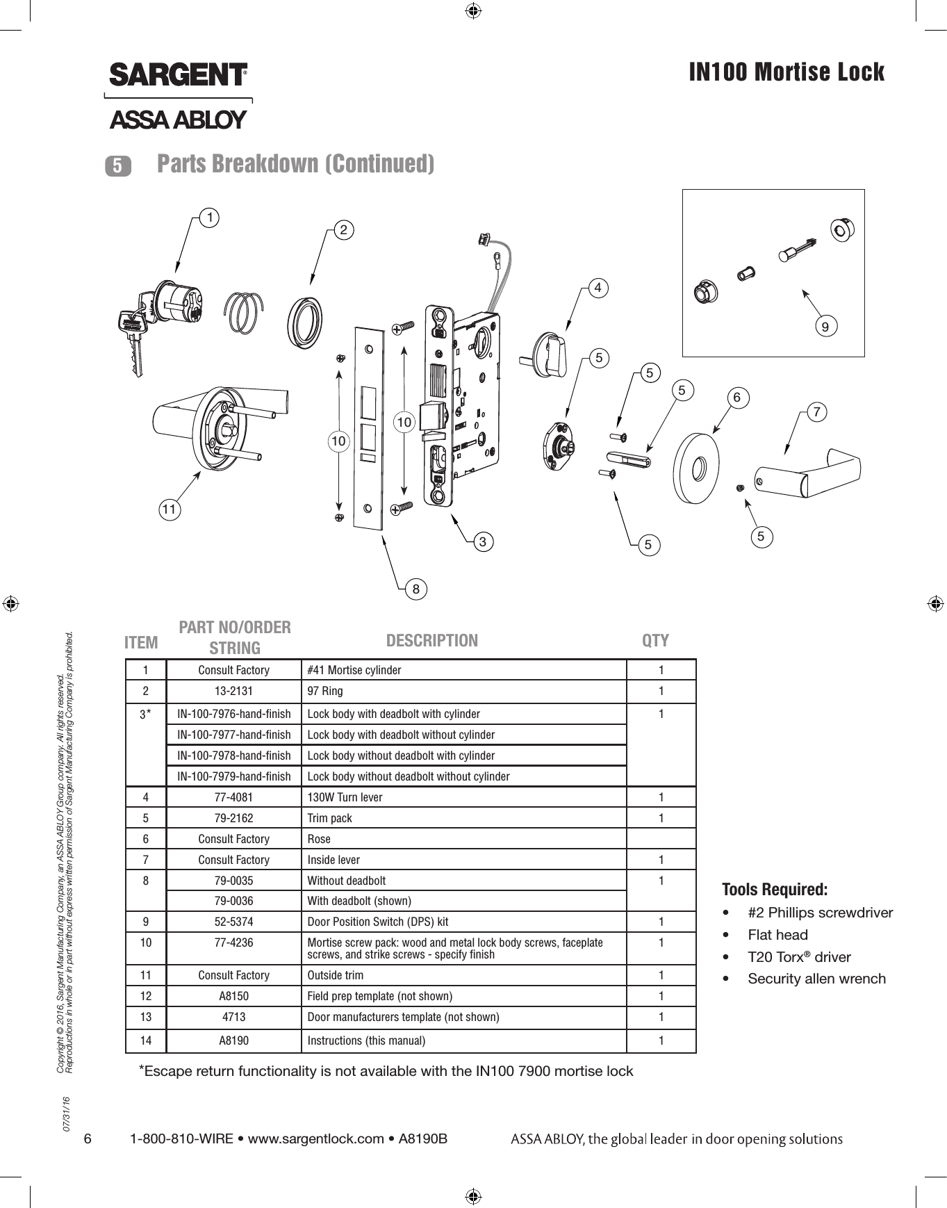
![07/31/161-800-810-WIRE • www.sargentlock.com • A8190B 5Copyright © 2016, Sargent Manufacturing Company, an ASSA ABLOY Group company. All rights reserved. Reproductions in whole or in part without express written permission of Sargent Manufacturing Company is prohibited.IN100 Mortise Lock Warning: SARGENT Mfg. Co. IN100 locksets utilizing a door position switch (DPS) are not rated for, or intended for use in life safety applications.51*4312** Specify finishParts BreakdownITEM PART NUMBER/ORDER STRING DESCRIPTION COLOR/TRIM QTY1 IN-100-EM01[locktype]*-IP-B HID iCLASS®, HID iCLASS SE® (SIO-enabled), HID iCLASS® Seos™, HID MIFARE® SE, HID DESfire® EV1 SE, HID Prox®Black 1IN-100-EM01[locktype]*-IP-W HID iCLASS®, HID iCLASS SE® (SIO-enabled), HID iCLASS® Seos™, HID MIFARE® SE, HID DESfire® EV1 SE, HID Prox®White 1IN-100-EM01[locktype]*-IP-MB-[xxx]* HID iCLASS®, HID iCLASS SE® (SIO-enabled), HID iCLASS® Seos™, HID MIFARE® SE, HID DESfire® EV1 SE, HID Prox®Black with metal trim 1IN-100-EM01[locktype]*-IP-MW-[xxx]* HID iCLASS®, HID iCLASS SE® (SIO-enabled), HID iCLASS® Seos™, HID MIFARE® SE, HID DESfire® EV1 SE, HID Prox®White with metal trim 1IN-100-EM01[locktype]*-IPS-B All credentials supported by IP option plus MIFARE Classic and DESfire EV1 Black 1IN-100-EM01[locktype]*-IPS-W All credentials supported by IP option plus MIFARE Classic and DESfire EV1 White 1IN-100-EM01[locktype]*-IPS-MB-[xxx]* All credentials supported by IP option plus MIFARE Classic and DESfire EV1 Black with metal trim 1IN-100-EM01[locktype]*-IPS-MW-[xxx]* All credentials supported by IP option plus MIFARE Classic and DESfire EV1 White with metal trim 12 IN-EM04 Mounting plate assembly 13 N/A AA battery 64 IN-100-EM02-B Inside Escutcheon Assembly with Privacy Button - Black Plastic Black 1IN-100-EM02-W Inside Escutcheon Assembly with Privacy Button - White Plastic WhiteIN-100-EM02-MB-xxx** Inside Escutcheon Assembly with Privacy Button - Black Plastic & Metal Trim Black with metal trimIN-100-EM02-MW-xxx** Inside Escutcheon Assembly with Privacy Button - White Plastic & Metal Trim White with metal trim*7976 / 7977 / 7978 / 7979 (example: IN-100-EM017976-IP-B)](https://usermanual.wiki/ASSALOY/SCYMCA1.User-Manual-A8190B-IN100-V3-Mortise/User-Guide-3061068-Page-5.png)