ASSALOY SCYMCA1 Aperio V3 iN100 RF Module User Manual A8190B IN100 V3 Bored
ASSA ABLOY Inc. Aperio V3 iN100 RF Module A8190B IN100 V3 Bored
UserManual.wiki
>
ASSALOY
>
SCYMCA1 User Manual
>
User Manual - A8190B IN100 (V3) Bored
Contents
1.
User Manual - A8190B IN100 (V3) Bored
2.
User Manual - A8190B IN100 (V3) Mortise
3.
User Manual - FM403 IN100 Mortise Instr
4.
User Manual - FM404 IN100 Bored Instr
5.
MANUAL
6.
MANUAL - MODULE INTEGRATION
User Manual - A8190B IN100 (V3) Bored
Navigation menu
Upload a User Manual
Namespaces
Wiki Guide
HTML
PDF
Info
Views
User Manual
Discussion / Help
Navigation

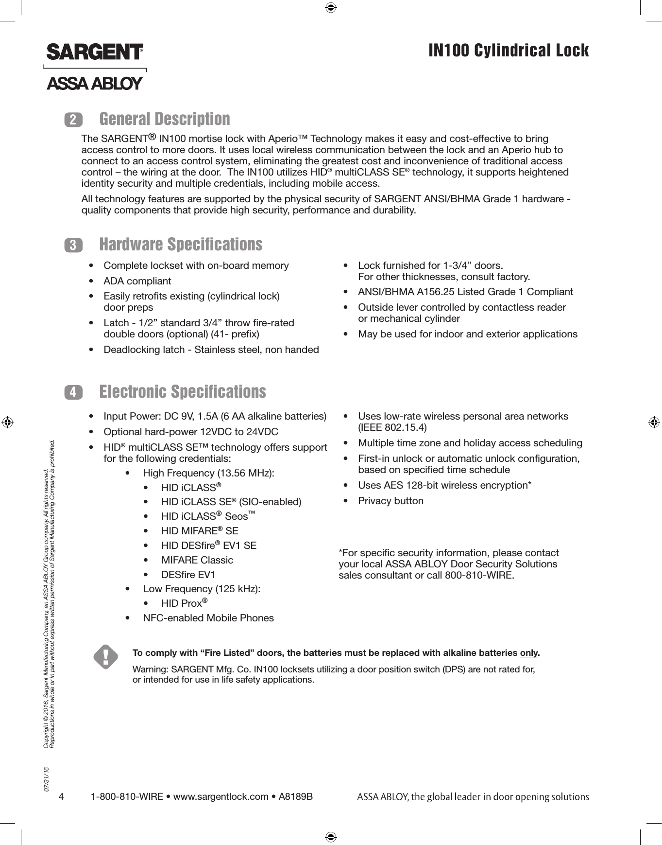
![07/31/161-800-810-WIRE • www.sargentlock.com • A8189B 5Copyright © 2016, Sargent Manufacturing Company, an ASSA ABLOY Group company. All rights reserved. Reproductions in whole or in part without express written permission of Sargent Manufacturing Company is prohibited.IN100 Cylindrical Lock 5Parts Breakdown* Specify finish14312ITEM PART NUMBER/ORDER STRING DESCRIPTION COLOR/TRIM QTY1 IN-100-EM0110G77-IP-B HID iCLASS®, HID iCLASS SE® (SIO-enabled), HID iCLASS® Seos™, HID MIFARE® SE, HID DESfire® EV1 SE, HID Prox®, NFC-enabled mobile phones Black 1IN-100-EM0110G77-IP-W HID iCLASS®, HID iCLASS SE® (SIO-enabled), HID iCLASS® Seos™, HID MIFARE® SE, HID DESfire® EV1 SE, HID Prox®, NFC-enabled mobile phonesWhite 1IN-100-EM0110G77-IP-MB-[xxx]* HID iCLASS®, HID iCLASS SE® (SIO-enabled), HID iCLASS® Seos™, HID MIFARE® SE, HID DESfire® EV1 SE, HID Prox®, NFC-enabled mobile phonesBlack with metal trim 1IN-100-EM0110G77-IP-MW-[xxx]* HID iCLASS®, HID iCLASS SE® (SIO-enabled), HID iCLASS® Seos™, HID MIFARE® SE, HID DESfire® EV1 SE, HID Prox®, NFC-enabled mobile phonesWhite with metal trim 1IN-100-EM0110G77-IPS-B All credentials supported by the IP option plus MIFARE Classic and DESfire EV1 Black 1IN-100-EM0110G77-IPS-W All credentials supported by the IP option plus MIFARE Classic and DESfire EV1 White 1IN-100-EM0110G77-IPS-MB-[xxx]* All credentials supported by the IP option plus MIFARE Classic and DESfire EV1 Black with metal trim 1IN-100-EM0110G77-IPS-MW-[xxx]* All credentials supported by the IP option plus MIFARE Classic and DESfire EV1 White with metal trim 12 IN-EM04 Mounting plate assembly 13 N/A AA battery (alkaline only) 64 IN-EM02-B Inside Escutcheon Assembly with Privacy Button - Black Plastic Black 1IN-EM02-W Inside Escutcheon Assembly with Privacy Button - White Plastic WhiteIN-EM02-MB-xxx* Inside Escutcheon Assembly with Privacy Button - Black Plastic & Metal Trim Black with metal trimIN-EM02-MW-xxx* Inside Escutcheon Assembly with Privacy Button - White Plastic & Metal Trim White with metal trim](https://usermanual.wiki/ASSALOY/SCYMCA1.User-Manual-A8190B-IN100-V3-Bored/User-Guide-3061067-Page-5.png)