ASSALOY SCYMCA1 Aperio V3 iN100 RF Module User Manual A8190B IN100 V3 Bored
ASSA ABLOY Inc. Aperio V3 iN100 RF Module A8190B IN100 V3 Bored
ASSALOY >
Contents
User Manual - A8190B IN100 (V3) Bored
A8189B
07/16
Copyright 2016, Sargent Manufacturing Company, an ASSA ABLOY Group company.
All rights reserved. Reproduction in whole or in part without the express written
permission of Sargent Manufacturing Company is prohibited.
with Aperio™
Technology
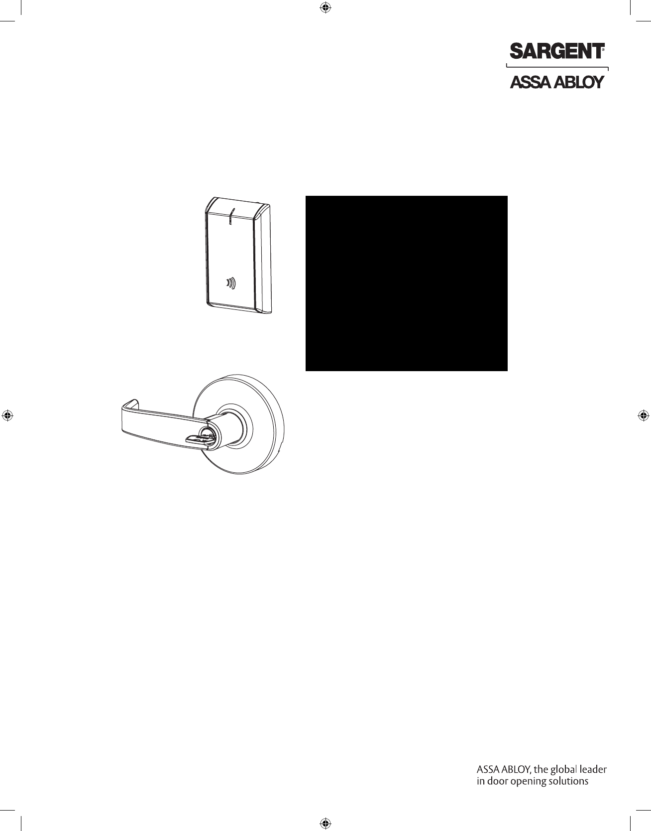
Cylindrical Lock
Installation Instructions
IN100

1-800-810-WIRE • www.sargentlock.com • A8189B
Copyright © 2016, Sargent Manufacturing Company, an ASSA ABLOY Group company. All rights reserved.
Reproductions in whole or in part without express written permission of Sargent Manufacturing Company is prohibited.
07/31/16
1
2
3
4
5
6
7
Table of Contents
Warning ...................................................................................3
General Description .................................................................4
Hardware Specifications .........................................................4
Electronic Specifications .........................................................4
Parts Breakdown .....................................................................5
Lock Installation ......................................................................7
Operational Check ................................................................19
Lock LED Indications ............................................................20
Changes or modifications to this device not expressly approved by ASSA ABLOY
could void the user’s authority to operate the equipment.
Warning
1
FCC:
This equipment has been tested and found to comply with the limits for a Class B digital device, pursuant to Part 15 of the
FCC Rules. These limits are designed to provide reasonable protection against harmful interference in a residential installation.
This equipment generates, uses, and can radiate radio frequency energy and, if not installed and used in accordance with the
instructions, may cause harmful interference to radio communications. However, there is no guarantee that interference will not
occur in a particular installation. If this equipment does cause harmful interference to radio or television reception, which can be
determined by turning the equipment off and on, the user is encouraged to try to correct the interference by one or more of the
following measures:
• Reorient or relocate the receiving antenna.
• Increase the separation between the equipment and receiver.
• Connect the equipment into an outlet on a circuit different from that to which the receiver is connected.
• Consult the dealer or an experienced radio/TV technician for help.
Industry Canada:
8
!
To avoid possible damage from electrostatic discharge (ESD), some basic precautions should be used when handling
electronic components:
• Minimize build-up of static by touching and/or maintaining contact with unpainted metal surfaces such as
door hinges, latches, and mounting plates especially when mounting electronic components such as readers
and controllers onto the door.
• Leave components (reader and controller) protected in their respective anti-static bags until ready for installation
• Do not touch pins, leads or solder connections on the circuit boards
This Class B digital apparatus meets all requirements of the Canadian Interference Causing Equipment Regulations. Operation is subject
to the following two conditions: (1) this device may not cause harmful interference, and (2) this device must accept any interference
received, including interference that may cause undesired operation.
Cet appareillage numérique de la classe B répond à toutes les exigences de l’interférence canadienne causant des règlements
d’équipement. L’opération est sujette aux deux conditions suivantes: (1) ce dispositif peut ne pas causer l’interférence nocive, et (2) ce
dispositif doit accepter n’importe quelle interférence reçue, y compris l’interférence qui peut causer l’opération peu désirée.
Under Industry Canada regulations, this radio transmitter may only operate using an antenna of a type and maximum (or lesser)
gain approved for the transmitter by Industry Canada. To reduce potential radio interference to other users, the antenna type
and its gain should be so chosen that the equivalent isotropically radiated power (e.i.r.p.) is not more than that necessary for
successful communication.
Conformément à la réglementation d’Industrie Canada, le présent émetteur radio peut fonctionner avec une antenne d’un type et
d’un gain maximal (ou inférieur) approuvé pour l’émetteur par Industrie Canada. Dans le but de réduire les risques de brouillage
radioélectrique à l’intention des autres utilisateurs, il faut choisir le type d’antenne et son gain de sorte que la puissance isotrope
rayonnée équivalente (p.i.r.e.) ne dépasse pas l’intensité nécessaire à l’établissement d’une communication satisfaisante.
Any retrofit or other field modification to a fire rated opening can potentially impact the fire rating of the opening, and SARGENT
Manufacturing makes no representations or warranties concerning what such impact may be in any specific situation. When retrofitting
any portion of an existing fire rated opening, or specifying and installing a new fire-rated opening, please consult with a code specialist
or local code official (Authority Having Jurisdiction) to ensure compliance with all applicable codes and ratings.
4 1-800-810-WIRE • www.sargentlock.com • A8189B
Copyright © 2016, Sargent Manufacturing Company, an ASSA ABLOY Group company. All rights reserved.
Reproductions in whole or in part without express written permission of Sargent Manufacturing Company is prohibited.
07/31/16
IN100 Cylindrical Lock
Warning: SARGENT Mfg. Co. IN100 locksets utilizing a door position switch (DPS) are not rated for,
or intended for use in life safety applications.
General Description
2
!To comply with “Fire Listed” doors, the batteries must be replaced with alkaline batteries only.
Hardware Specifications
3
Electronic Specifications
4
• Uses low-rate wireless personal area networks
(IEEE 802.15.4)
• Multiple time zone and holiday access scheduling
• First-in unlock or automatic unlock configuration,
based on specified time schedule
• Uses AES 128-bit wireless encryption*
• Privacy button
• Input Power: DC 9V, 1.5A (6 AA alkaline batteries)
• Optional hard-power 12VDC to 24VDC
• HID® multiCLASS SE™ technology offers support
for the following credentials:
• High Frequency (13.56 MHz):
• HID iCLASS®
• HID iCLASS SE® (SIO-enabled)
• HID iCLASS® Seos™
• HID MIFARE® SE
• HID DESfire® EV1 SE
• MIFARE Classic
• DESfire EV1
• Low Frequency (125 kHz):
• HID Prox®
• NFC-enabled Mobile Phones
*For specific security information, please contact
your local ASSA ABLOY Door Security Solutions
sales consultant or call 800-810-WIRE.
• Complete lockset with on-board memory
• ADA compliant
• Easily retrofits existing (cylindrical lock)
door preps
• Latch - 1/2” standard 3/4” throw fire-rated
double doors (optional) (41- prefix)
• Deadlocking latch - Stainless steel, non handed
• Lock furnished for 1-3/4” doors.
For other thicknesses, consult factory.
• ANSI/BHMA A156.25 Listed Grade 1 Compliant
• Outside lever controlled by contactless reader
or mechanical cylinder
• May be used for indoor and exterior applications
The SARGENT® IN100 mortise lock with Aperio™ Technology makes it easy and cost-effective to bring
access control to more doors. It uses local wireless communication between the lock and an Aperio hub to
connect to an access control system, eliminating the greatest cost and inconvenience of traditional access
control – the wiring at the door. The IN100 utilizes HID® multiCLASS SE® technology, it supports heightened
identity security and multiple credentials, including mobile access.
All technology features are supported by the physical security of SARGENT ANSI/BHMA Grade 1 hardware -
quality components that provide high security, performance and durability.
07/31/16
1-800-810-WIRE • www.sargentlock.com • A8189B 5
Copyright © 2016, Sargent Manufacturing Company, an ASSA ABLOY Group company. All rights reserved.
Reproductions in whole or in part without express written permission of Sargent Manufacturing Company is prohibited.
IN100 Cylindrical Lock
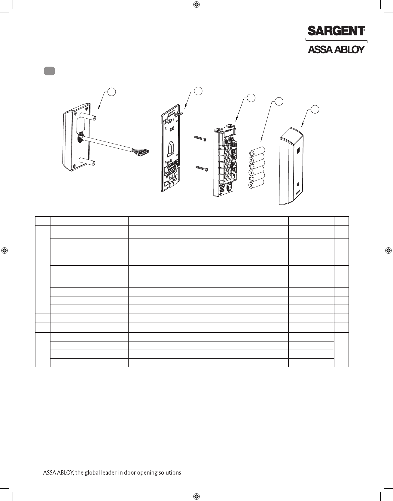
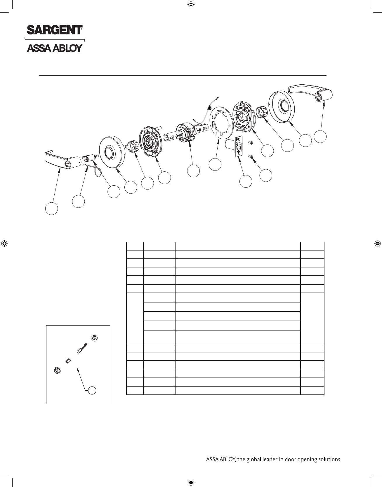
5Parts Breakdown
* Specify finish
1
4
3
1
2
ITEM PART NUMBER/ORDER STRING DESCRIPTION COLOR/TRIM QTY
1 IN-100-EM0110G77-IP-B HID iCLASS®, HID iCLASS SE® (SIO-enabled), HID iCLASS® Seos™, HID MIFARE®
SE, HID DESfire® EV1 SE, HID Prox®, NFC-enabled mobile phones
Black 1
IN-100-EM0110G77-IP-W HID iCLASS®, HID iCLASS SE® (SIO-enabled), HID iCLASS® Seos™, HID MIFARE®
SE, HID DESfire® EV1 SE, HID Prox®, NFC-enabled mobile phones
White 1
IN-100-EM0110G77-IP-MB-[xxx]* HID iCLASS®, HID iCLASS SE® (SIO-enabled), HID iCLASS® Seos™, HID MIFARE®
SE, HID DESfire® EV1 SE, HID Prox®, NFC-enabled mobile phones
Black with metal trim 1
IN-100-EM0110G77-IP-MW-[xxx]* HID iCLASS®, HID iCLASS SE® (SIO-enabled), HID iCLASS® Seos™, HID MIFARE®
SE, HID DESfire® EV1 SE, HID Prox®, NFC-enabled mobile phones
White with metal trim 1
IN-100-EM0110G77-IPS-B All credentials supported by the IP option plus MIFARE Classic and DESfire EV1 Black 1
IN-100-EM0110G77-IPS-W All credentials supported by the IP option plus MIFARE Classic and DESfire EV1 White 1
IN-100-EM0110G77-IPS-MB-[xxx]* All credentials supported by the IP option plus MIFARE Classic and DESfire EV1 Black with metal trim 1
IN-100-EM0110G77-IPS-MW-[xxx]* All credentials supported by the IP option plus MIFARE Classic and DESfire EV1 White with metal trim 1
2 IN-EM04 Mounting plate assembly 1
3 N/A AA battery (alkaline only) 6
4 IN-EM02-B Inside Escutcheon Assembly with Privacy Button - Black Plastic Black 1
IN-EM02-W Inside Escutcheon Assembly with Privacy Button - White Plastic White
IN-EM02-MB-xxx* Inside Escutcheon Assembly with Privacy Button - Black Plastic & Metal Trim Black with metal trim
IN-EM02-MW-xxx* Inside Escutcheon Assembly with Privacy Button - White Plastic & Metal Trim White with metal trim
6 1-800-810-WIRE • www.sargentlock.com • A8189B
Copyright © 2016, Sargent Manufacturing Company, an ASSA ABLOY Group company. All rights reserved.
Reproductions in whole or in part without express written permission of Sargent Manufacturing Company is prohibited.
07/31/16
IN100 Cylindrical Lock
Parts Breakdown (Continued)
*Adapter Plate/Spacer (10-0847)
is only shipped with orders
that specify 1-3/8” doors.
Tools Required:
• #2 Phillips screwdriver
• Flat head screwdriver
• Security allen wrench
ITEM
PART NO./ORDER
STRING DESCRIPTION QTY.
13
1
2
345
6
7
11
5412
9
10
8
*
1 --- Outside Lever (Reference Catalog for Available Styles) 1
2 10-0043 Lever Retainer Key (In Screw Pack 10-2052) 1
3 --- Cylinder Assembly (Reference Catalog for Available Cylinders) 1
4 --- Rose (Reference Catalog for Available Styles) 2
5 10-0792 Spacer Bushing 2
6 10-3049 Outside Rose Spring Assembly 1
7** 10-3452 Lockbody Assembly 10G77 (Standard Cylinder) 1
10-3453 Lockbody - LFIC (Removable Core)
10-3454 Lockbody - SFIC
10-3455 Lockbody - Keso
10-3456 Lockbody - Medeco Keymark LFIC & Schlage Full Size
Interchangeable Core
8 10-0847 Adapter Plate/Spacer (Only Included With 1-3/8” Thick Doors) 2
9 10-3192 Latch Assembly 1
10 10-2052 Screw Pack 2
11 10-3048 Inside Rose Spring Assembly 1
12 --- Inside Lever (Reference Catalog for Available Styles) 1
13 52-5374 Door Position Switch Kit (SPDT) 1
**The IN100 10G77 cylindrical lock supports Escape Return functionality.
07/31/16
1-800-810-WIRE • www.sargentlock.com • A8189B 7
Copyright © 2016, Sargent Manufacturing Company, an ASSA ABLOY Group company. All rights reserved.
Reproductions in whole or in part without express written permission of Sargent Manufacturing Company is prohibited.
IN100 Cylindrical Lock
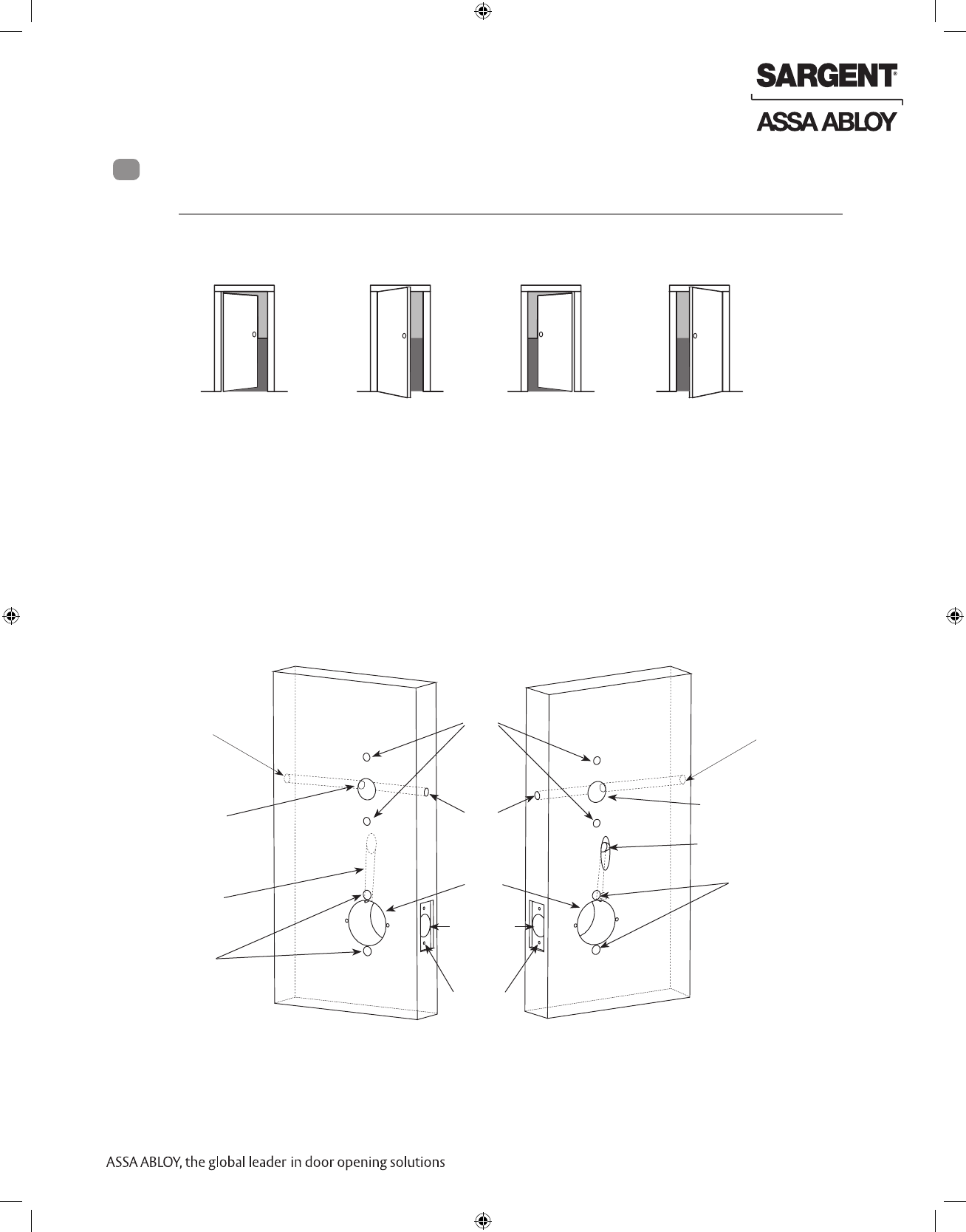
A. Verify Hand and Bevel of Door
Stand on outside of locked door when determining door hand.
Lock Installation
LH
Left Hand
Hinges Left
Open Inward
LHRB
Left Hand
Reverse Bevel
Hinges Left
Open Outward
RH
Right Hand
Hinges Right
Open Inward
RHRB
Right Hand
Reverse Bevel
Hinges Right
Open Outward
Fig. 1A
1 Prepare Door
6
B. Prepare Door
Prior to installation, all holes must be free of burrs, debris and sharp edges.
Prepare door according to appropriate template (see website www.intelligentopenings.com).
• Field Template: A8149 (ships with product)
• Door Manufacturer’s Template: 4712
Inside of DoorOutside of Door
Fig. 1B Wood Door Preparation
Cable Hole
Through-bolt
Holes
Cable Hole
Pre-drilled
Tap Holes
Cylindrical
Pocket
and
Latch
Holes
Through-bolt Holes
External
DPS
holes
Through-bolt Holes
Lever Handle
Hole
Raceway for
Lockbody
Harness
Raceway for
Lockbody
Harness
Raceway for Power
(Optional)
Raceway for Power
(Optional)
8 1-800-810-WIRE • www.sargentlock.com • A8189B
Copyright © 2016, Sargent Manufacturing Company, an ASSA ABLOY Group company. All rights reserved.
Reproductions in whole or in part without express written permission of Sargent Manufacturing Company is prohibited.
07/31/16
IN100 Cylindrical Lock
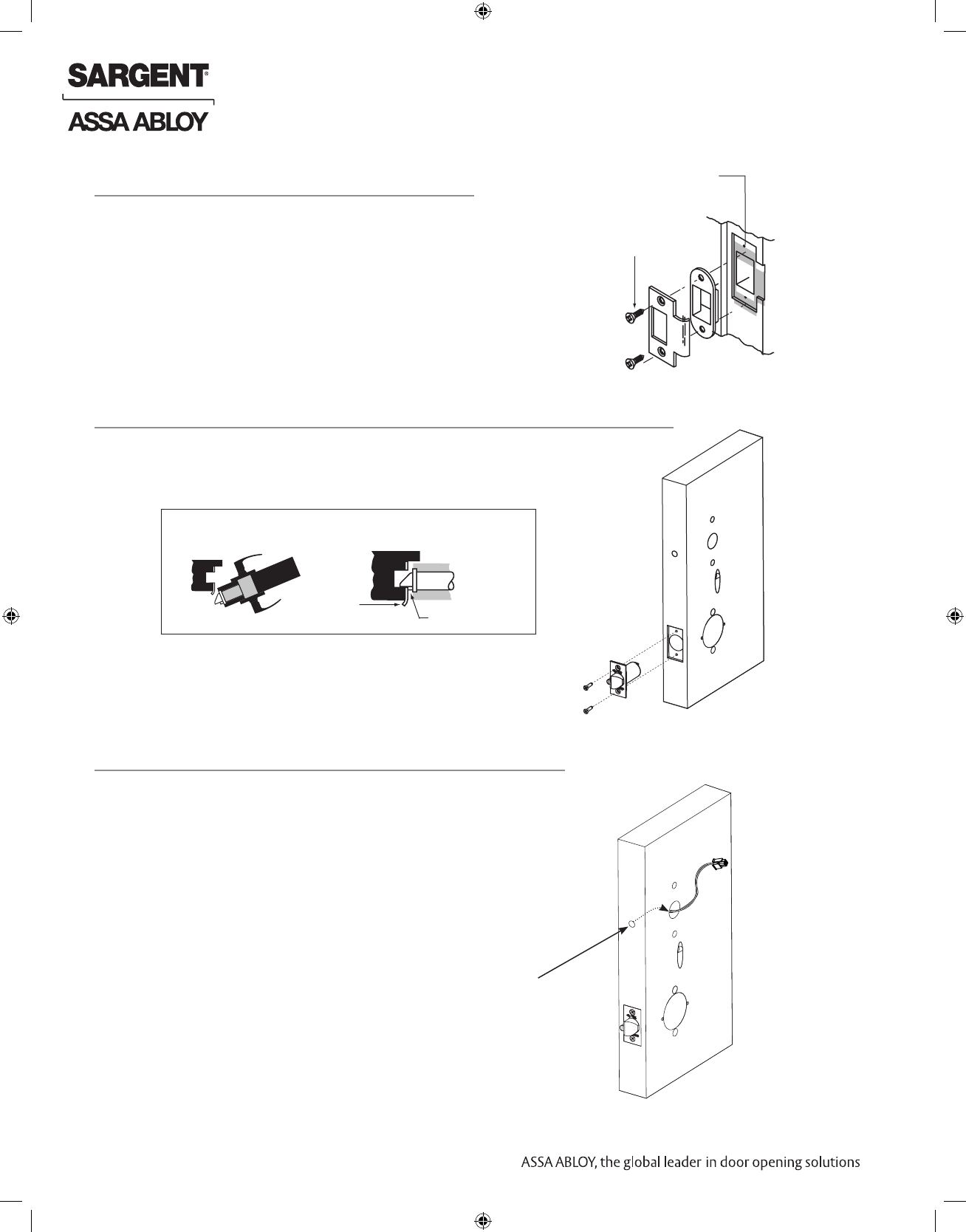
Install strike in the door frame (Fig. 2).
2 Install Strike
Fig. 2
Centerline of
Latch Front and
Strike
(2) #8-32 x 3/4"
Latch Screws
1. Install latch with beveled bolt facing the strike.
2. Attach with two screws but DO NOT tighten completely at this time.
See section 8 - Secure Lock to the Door.
3 Install Latchbolt
Fig. 3B
Strike
IMPORTANT: Latch bevel must match door bevel and
deadlocking latch must stop on strike when door is closed.
Deadlocking Latch
Inside of Door
Fig. 3A
4 Install Door Position Switch (DPS)
1. Push wires through raceway toward lock prep.
2. Push DPS firmly into place by hand.
Note: DO NOT TAP SWITCH WITH ANY TOOL.
3. Install magnet into door frame. Push firmly into place by hand.
See A7983.
4. To connect DPS to lock controller per diagram, refer to the wiring in
Step #10 (Page 15).
Fig. 4
Inside of Door
DPS
(Door Position Switch)
CAUTION: if DPS is not installed or is installed
improperly, door status monitoring features will
not function.
07/31/16
1-800-810-WIRE • www.sargentlock.com • A8189B 9
Copyright © 2016, Sargent Manufacturing Company, an ASSA ABLOY Group company. All rights reserved.
Reproductions in whole or in part without express written permission of Sargent Manufacturing Company is prohibited.
IN100 Cylindrical Lock
The lock is shipped “preset” and does not require adjustment for 1-3/4” thick doors.
5
Lock Adjustments
NOTE: Adjusting for a thicker door requires removal of the outside lever, scalp and spacer bushing;
see the following sections.
If preset lock does not require adjustment, proceed to Section 7 - Install Lock.
A. Lock Preset:
• Lockbody holes: 12 and 6 o’clock (Fig. 5).
Outside of Door
Fig. 5
Door thickness:
1-3/4” thick
Preset Lock
10 1-800-810-WIRE • www.sargentlock.com • A8189B
Copyright © 2016, Sargent Manufacturing Company, an ASSA ABLOY Group company. All rights reserved.
Reproductions in whole or in part without express written permission of Sargent Manufacturing Company is prohibited.
07/31/16
IN100 Cylindrical Lock
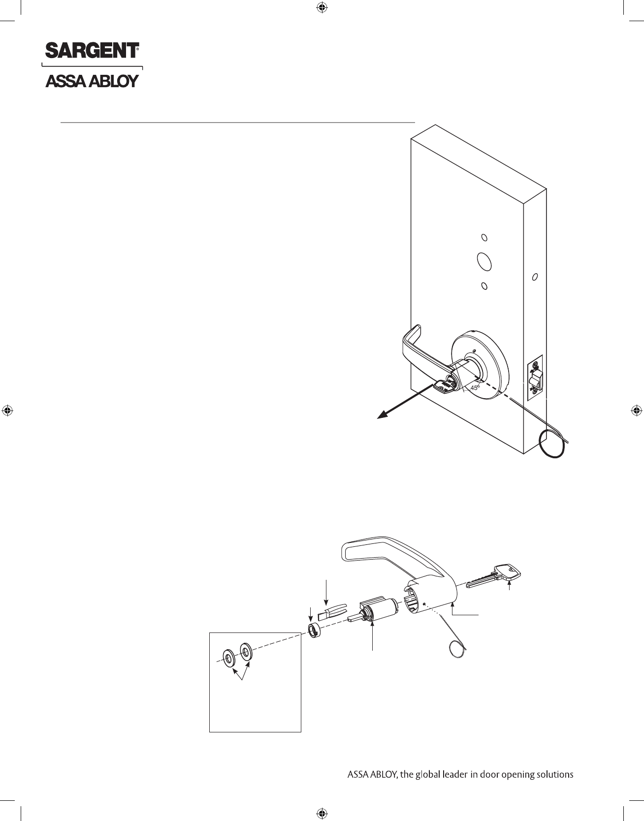
A. Remove Outside Lever
1. Insert key, rotate 45° clockwise and hold.
2. Depress lever retainer with push pin tool (provided).
3. Pull lever outward.
6 Through-Bolt and Door Thickness Adjustment (If Required)
Outside of Door
Fig. 6A
B. How To Change Cylinder (If Necessary)
1. With outside lever in hand, use standard pliers
to pull out cylinder retainer.
2. Remove key and cylinder from lever.
3. Insert new cylinder.
4. Secure by pressing cylinder retainer flush with the lever.
Cylinder
Cylinder
Retainer
Cylinder
Spacer
Outside
Lever
Key
Washers required for
30- prefix
(10 Line Lever)
to accept
Schlage cylinder
(no cylinder provided)
Fig. 6B Push Pin Tool
07/31/16
1-800-810-WIRE • www.sargentlock.com • A8189B 11
Copyright © 2016, Sargent Manufacturing Company, an ASSA ABLOY Group company. All rights reserved.
Reproductions in whole or in part without express written permission of Sargent Manufacturing Company is prohibited.
IN100 Cylindrical Lock
1. (If necessary) remove outside lever, scalp
and spacer bushing (Fig. 6C).
C. Through-Bolt and Door Thickness Adjustment
Fig. 6C
Fig. 6C Detail
1-3/4” Thick Doors
2” Thick Doors
2. Rotate mounting plate to either align with through-bolt holes in
door, or adjust for proper door thickness (Fig. 6D).
Refer to markings on through-bolt post (Fig. 6C Detail).
3. Re-install spacer bushing to align with back
of lever, scalp, and lever (Fig. 6D).
Fig. 6D
Outside Lever
Scalp
Spacer Bushing
12 1-800-810-WIRE • www.sargentlock.com • A8189B
Copyright © 2016, Sargent Manufacturing Company, an ASSA ABLOY Group company. All rights reserved.
Reproductions in whole or in part without express written permission of Sargent Manufacturing Company is prohibited.
07/31/16
IN100 Cylindrical Lock
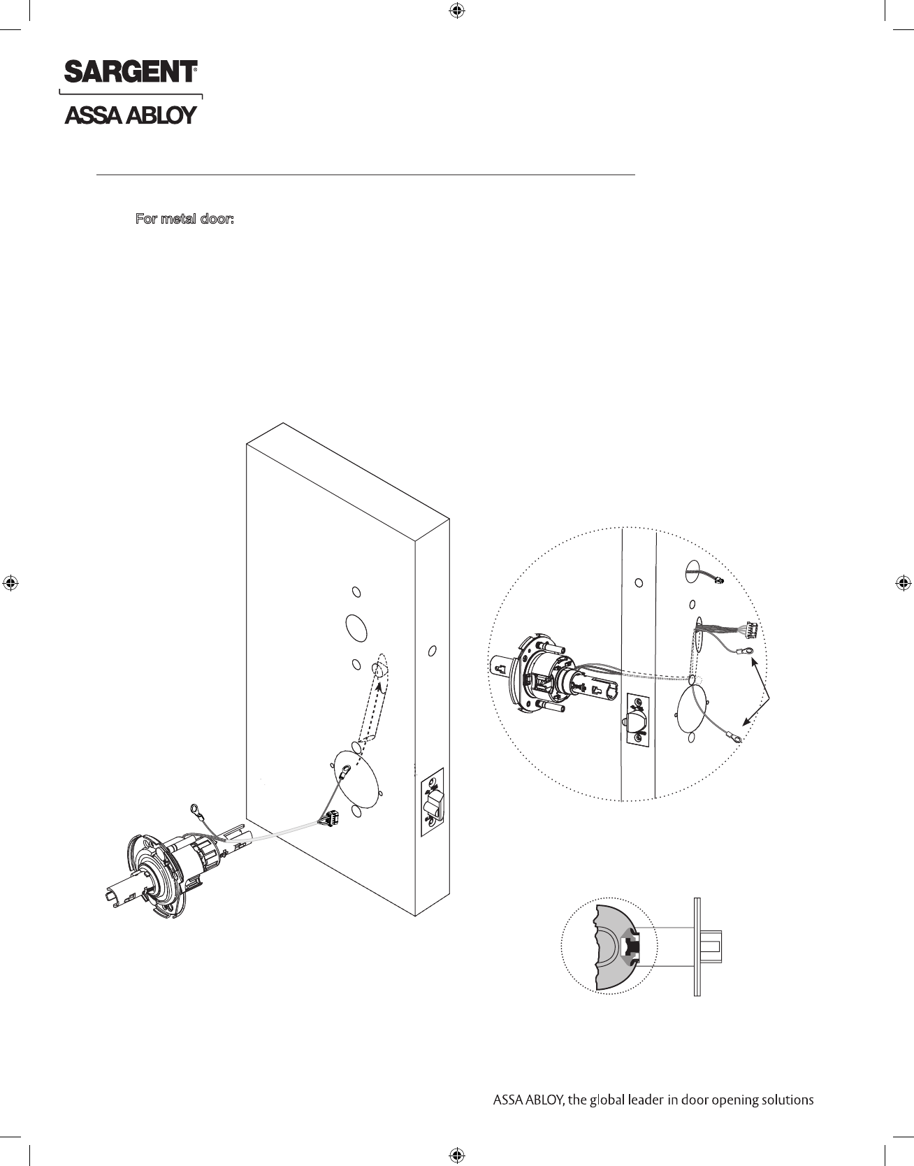
7 Install Lock
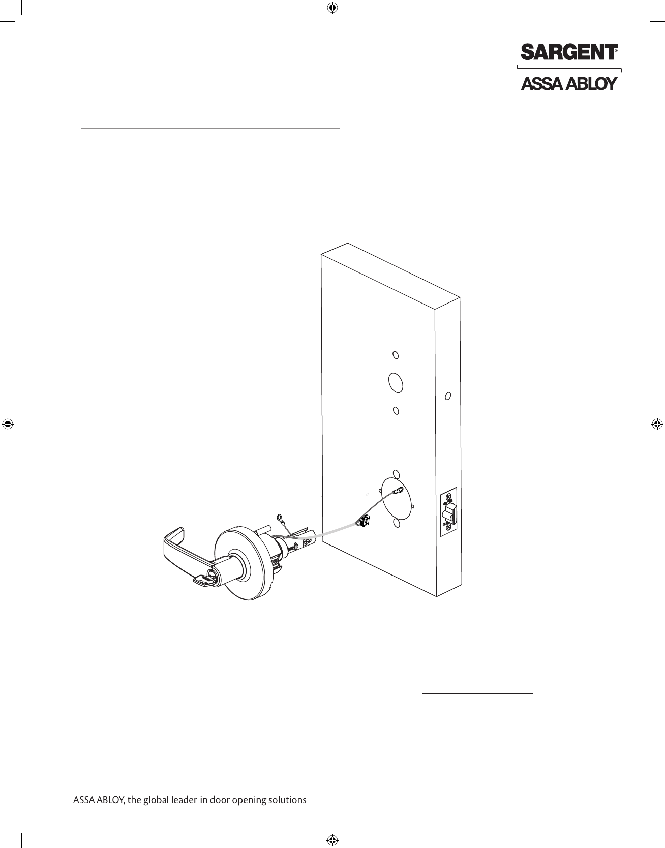
1. From outside of door feed lockbody harness into the lockbody hole (Fig. 7A).
For metal door: Feed harness through inside of door (not shown).
2. Continue to feed harness into raceway (towards top of door), exiting raceway
hole on inside of door (Fig. 7B).
3. Slide lockbody into cross-bore hole from outside of door.
4. Lockbody must engage both the latch unit prongs and tail piece (Fig. 7C).
IMPORTANT:
• Door must remain open during installation (use door stop)
• Lockbody must be centered in the door
• Tuck excess wires into raceway to avoid pinching or damaging wires
Fig. 7B Detail
Inside of Door
Outside of Door
Fig. 7A
Ground Ring
Terminals
NOTE: Cable lengths exaggerated for illustrative purposes.
Fig. 7C Detail
07/31/16
1-800-810-WIRE • www.sargentlock.com • A8189B 13
Copyright © 2016, Sargent Manufacturing Company, an ASSA ABLOY Group company. All rights reserved.
Reproductions in whole or in part without express written permission of Sargent Manufacturing Company is prohibited.
IN100 Cylindrical Lock
Inside of
Door
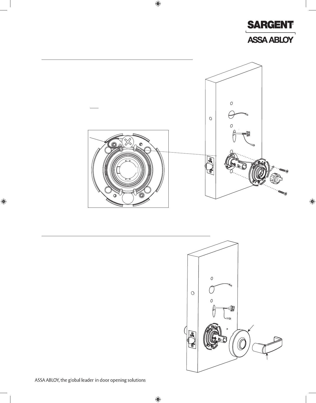
9 Assemble Inside Trim
1. Verify spacer bushing is inserted horizontally and
aligned with lever (Fig. 9).
2. Place rose over shaft of lockbody against the
surface of the door; hand-tighten, turning clockwise.
3. Attach lever. Push until engaged.
8 Secure Lock to the Door
1. Slide inside rose assembly and spacer bushing over lockbody.
2. Position ground lug between (top) #10-32x1-1/4” through-bolt
and rose assembly (Fig. 8A).
NOTE: Proper placement of ground wire (Fig. 8B) will prevent
pinching/damage to the ground wire.
3. Secure rose assembly with (2) #10-32x1-1/4” through-bolts.
4. Secure latch by fully tightening (2) #6 x 3/4” self-tapping screws
(refer to previous section 3 - Install Latchbolt).
Fig. 8A
Inside of Door
Fig. 8B Detail
Ground Wire
NOTE: Cable lengths exaggerated for illustrative purposes.
Fig. 9
Rose
Inside lever
14 1-800-810-WIRE • www.sargentlock.com • A8189B
Copyright © 2016, Sargent Manufacturing Company, an ASSA ABLOY Group company. All rights reserved.
Reproductions in whole or in part without express written permission of Sargent Manufacturing Company is prohibited.
07/31/16
IN100 Cylindrical Lock
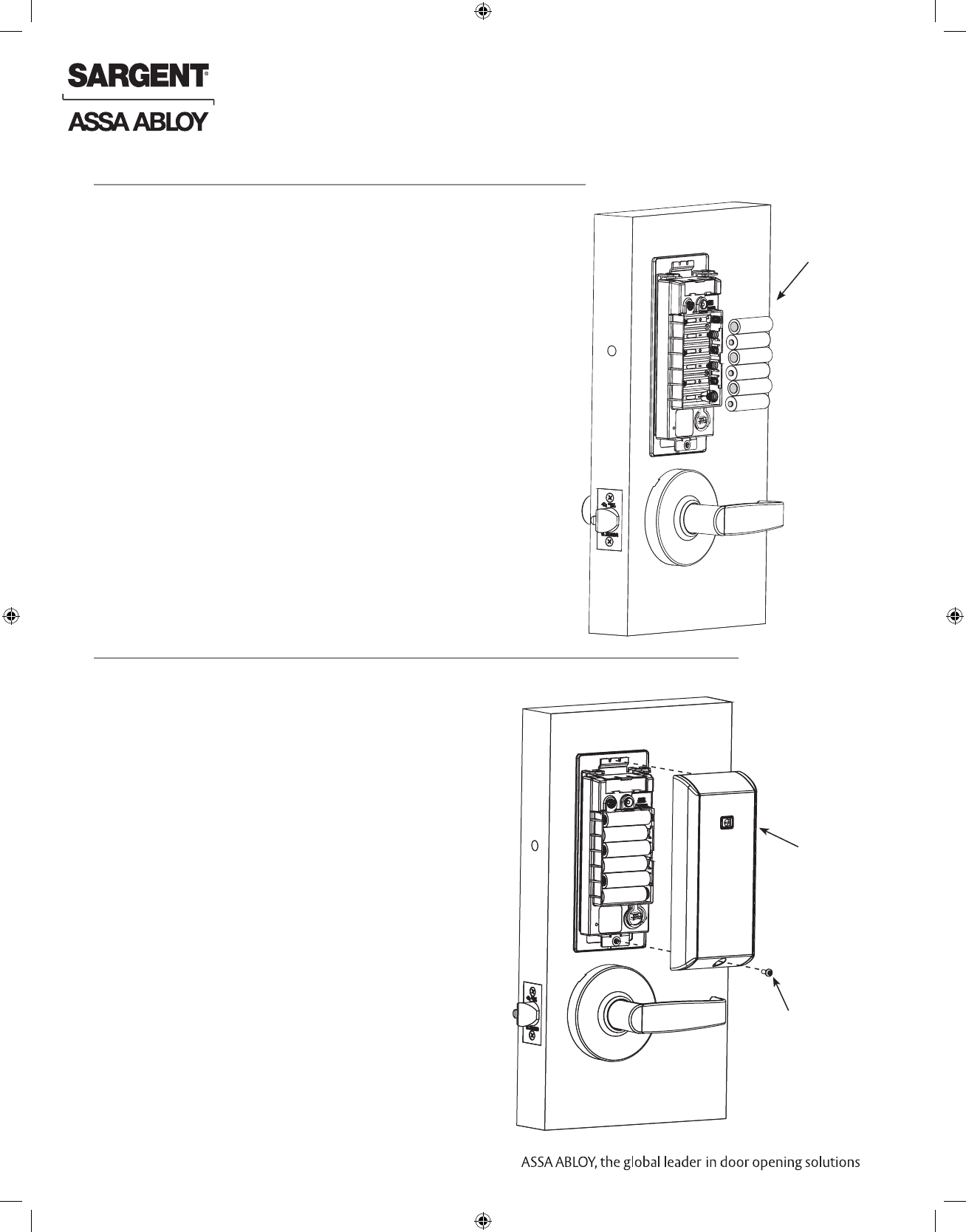
10
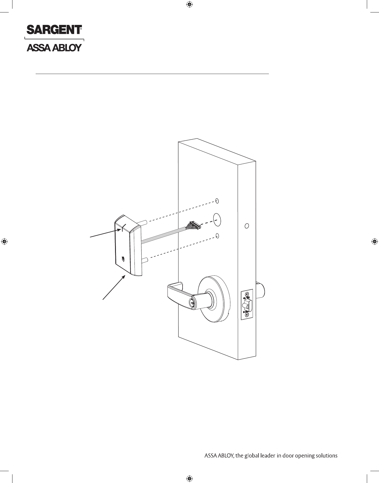
Outside Reader Installation
1. Orient the reader so the LED lens is at the top (Fig. 10A).
2. Feed the cable/connector through the door (from outside to inside).
3. Install the reader to the outside of door by aligning the mounting posts with the door
preparation holes. Hold the reader flush against door while ensuring proper alignment.
Fig. 10A
Outside of Door
LED
Reader Assembly
with Harness
NOTE: Cable lengths exaggerated for illustrative purposes.
07/31/16
1-800-810-WIRE • www.sargentlock.com • A8189B 15
Copyright © 2016, Sargent Manufacturing Company, an ASSA ABLOY Group company. All rights reserved.
Reproductions in whole or in part without express written permission of Sargent Manufacturing Company is prohibited.
IN100 Cylindrical Lock
Fig. 10B
*Gasket is required for outdoor installations. Do not use gasket for fire-rated openings.
If installing with gasket; separate gasket from mounting plate to feed cables/connectors
through holes as indicated (Fig. 10B).
Once cables/connectors are fed through, reattach gasket to mounting plate.
Lockbody
Harness
Ground Ring
Terminal
Through-bolt
NOTE: Cable lengths exaggerated for illustrative purposes
Gasket*
Mounting
Plate
Door Position
Switch
Through-bolt
Reader Harness
10
Outside Reader Installation (Continued)
Fig. 10C
6. Secure ground lug with #6-32 machine screw (Fig. 10C).
4. Feed the reader harness and DPS connectors through the inside mounting assembly
(and gasket if required*). See Figure 11B.
IMPORTANT: Do not run wires through bottom flange hole in plate (Fig. 11B, C) - it will damage wires and
the controller connector. Route wires around flange, do not route wires through the flange hole (Fig. 11C).
5. Tuck excess cable into wire hole on inside of door.
6. Begin to secure the mounting assembly by partially tightening the (2) through-bolts on the
inside of the door while ensuring proper alignment as you secure the reader (Fig. 11B).
16 1-800-810-WIRE • www.sargentlock.com • A8189B
Copyright © 2016, Sargent Manufacturing Company, an ASSA ABLOY Group company. All rights reserved.
Reproductions in whole or in part without express written permission of Sargent Manufacturing Company is prohibited.
07/31/16
IN100 Cylindrical Lock
10
Outside Reader Installation (Continued)
Secure the following connectors to their respective terminals (Fig. 11D):
A. Secure the 4-pin DPS connector.
B. Secure the 10-pin lock body assembly connector.
CAUTION - Do not touch or allow debris to enter connector contacts.
IMPORTANT: Do not run wires through bottom hole in plate - it will
damage wires and the controller connector.
Route wires around flange, do not route wires through
the flange hole (Fig. 11B, D).
E. Secure the 24-pin card reader connector (Fig. 11F).
Reader
(24-pin)
Board-to-Board
Connector
Fig. 11F
D
D. Secure the mounting assembly while ensuring proper
alignment of outside reader and tighten the (2) through-bolts
on the inside of the door to secure the reader (Fig. 11E).
Secure Mounting Plate
Installation of Connectors
*NOTE: Optional 2-pin external 9-24VDC power connector.
C. When all connections have been made, tuck excess cable
into wire hole on inside of door.
Ground
Lug
DPS (4-pin)
A
Lock
Body
(10-pin)
Fig. 11D
B
9-24VDC
Power*
Fig. 11E
Fully
tighten
07/31/16
1-800-810-WIRE • www.sargentlock.com • A8189B 17
Copyright © 2016, Sargent Manufacturing Company, an ASSA ABLOY Group company. All rights reserved.
Reproductions in whole or in part without express written permission of Sargent Manufacturing Company is prohibited.
IN100 Cylindrical Lock
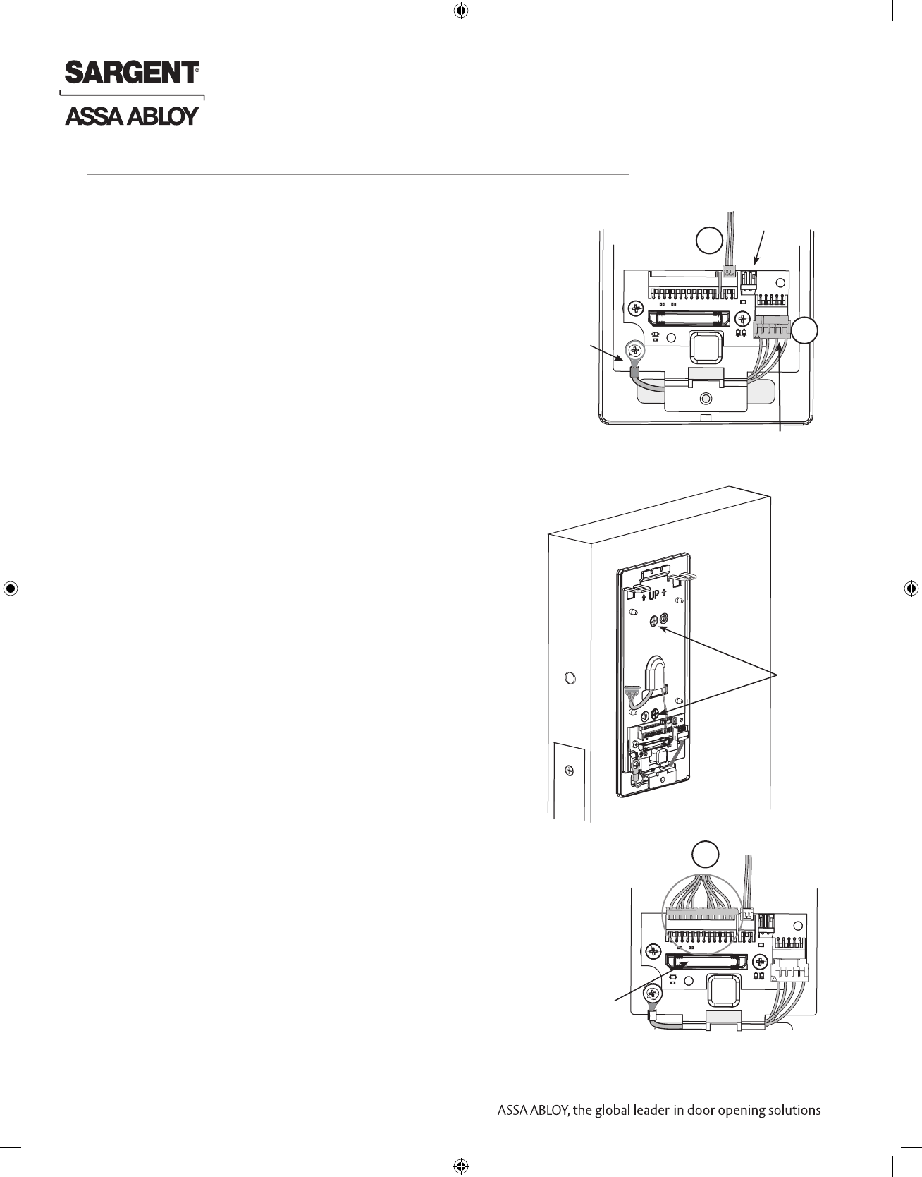
Controller
Fig. 12
11
Installation of Inside Component Assembly (Controller)
1. Insert top tabs of controller into slots on mounting plate (Fig. 12).
2. Ensure proper alignment of board-to-board connectors while pivoting bottom of controller
toward door until tab on bottom snaps securely into place on mounting plate.
CAUTION: To avoid possible damage to board-to-board connectors,
care should be taken when securing controller to mounting
plate. If there is resistance when securing, detach controller
to determine cause before re-attaching controller.
18 1-800-810-WIRE • www.sargentlock.com • A8189B
Copyright © 2016, Sargent Manufacturing Company, an ASSA ABLOY Group company. All rights reserved.
Reproductions in whole or in part without express written permission of Sargent Manufacturing Company is prohibited.
07/31/16
IN100 Cylindrical Lock
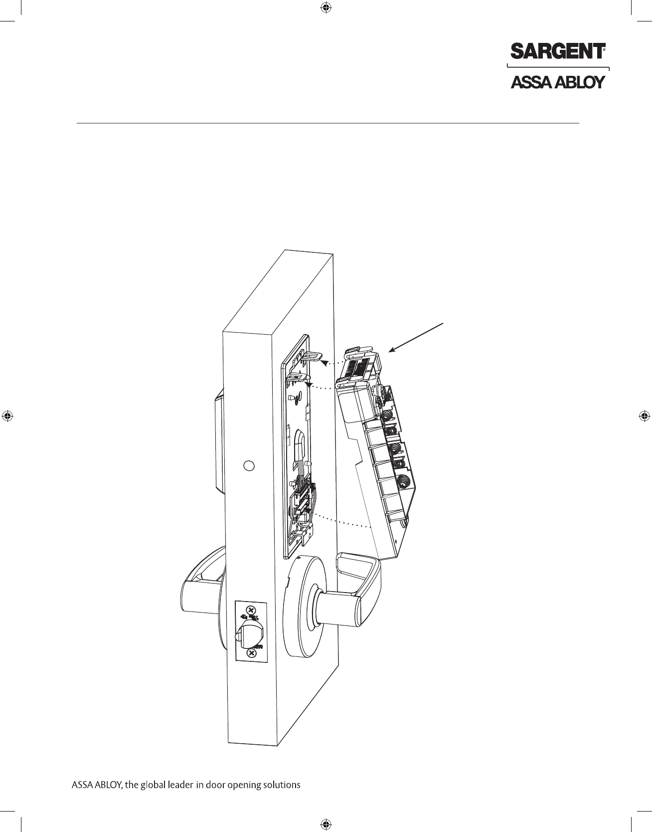
Inside
Cover
Security Allen
Screw
Fig. 12
Fig. 13
1. Assemble cover by hooking top edge on inside
mounting plate.
2. Carefully press bottom of cover toward door without
pinching or damaging wires.
3. Secure cover utilizing security allen wrench (provided).
AA Batteries (6)
13
Battery Installation
14
Inside Cover Installation
1. Place (6) “AA” alkaline batteries in the compartment, being
careful to align polarity properly (Fig. 12).
2. After batteries are installed, there is a slight delay; then red and
green flash*, audible “beep” and lock motor will cycle.
*See Section 8 - LED Indications for more information
07/31/16
1-800-810-WIRE • www.sargentlock.com • A8189B 19
Copyright © 2016, Sargent Manufacturing Company, an ASSA ABLOY Group company. All rights reserved.
Reproductions in whole or in part without express written permission of Sargent Manufacturing Company is prohibited.
IN100 Cylindrical Lock
1. Insert key into cylinder and rotate (Fig. 14A).
There should be no friction against lock case, wire
harness or any other obstructions.
2. Check that the key retracts the latch.
The key should rotate freely.
3. Try the inside lever; ensure it retracts latch.
4. Present a valid credential* (Fig. 14B) to unlock
outside lever; turn lever handle to ensure latch retracts.
Operational Check
7
Fig. 14B
Note: The credential should approach the inscription
on the reader as indicated (Fig. 14B) to ensure
the credential is read properly.
Do not wave credential.
Fig. 14A
20 1-800-810-WIRE • www.sargentlock.com • A8189B
Copyright © 2016, Sargent Manufacturing Company, an ASSA ABLOY Group company. All rights reserved.
Reproductions in whole or in part without express written permission of Sargent Manufacturing Company is prohibited.
07/31/16
IN100 Cylindrical Lock
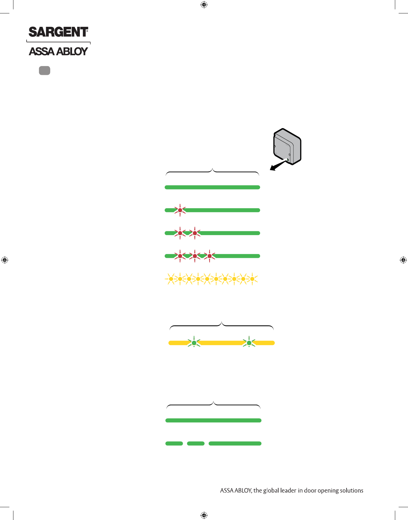
8LED Indications
Communication Hub LED indications
The communication hub has a single LED. It supports an optical scheme of red,
green and yellow.
The indication scheme is described by the figures below:
Figure 1.
Communication hub normal
operation LED indication 2 sec.
Online Green
Aperio® lock Green + one
red flash
offline
EAC offline
Aperio® lock and Green + three
red flashes
EAC offline
UHF Yellow + off,
fast flash
communication
Some special LED indication schemes are
used during lock maintenance actions:
2 sec.
Figure 2.
Communication hub
maintenance LED indication Pairing active Yellow + green
Ethernet LED indication
The LED on the AH40 communication hub indicates both the
status of the Ethernet link level and ethernet communication:
2 sec.
Figure 3.
AH40 Communication hub
Ethernet LED indication Ethernet link
connected Green
Ethernet Green +
communication off fast flash
Green + two red flashes
*For more information, refer to Aperio Online Quick Installation Guide
Document No: ST-001322-PF Date: 2015-12-23
07/31/16
1-800-810-WIRE • www.sargentlock.com • A8189B 21
Copyright © 2016, Sargent Manufacturing Company, an ASSA ABLOY Group company. All rights reserved.
Reproductions in whole or in part without express written permission of Sargent Manufacturing Company is prohibited.
IN100 Cylindrical Lock
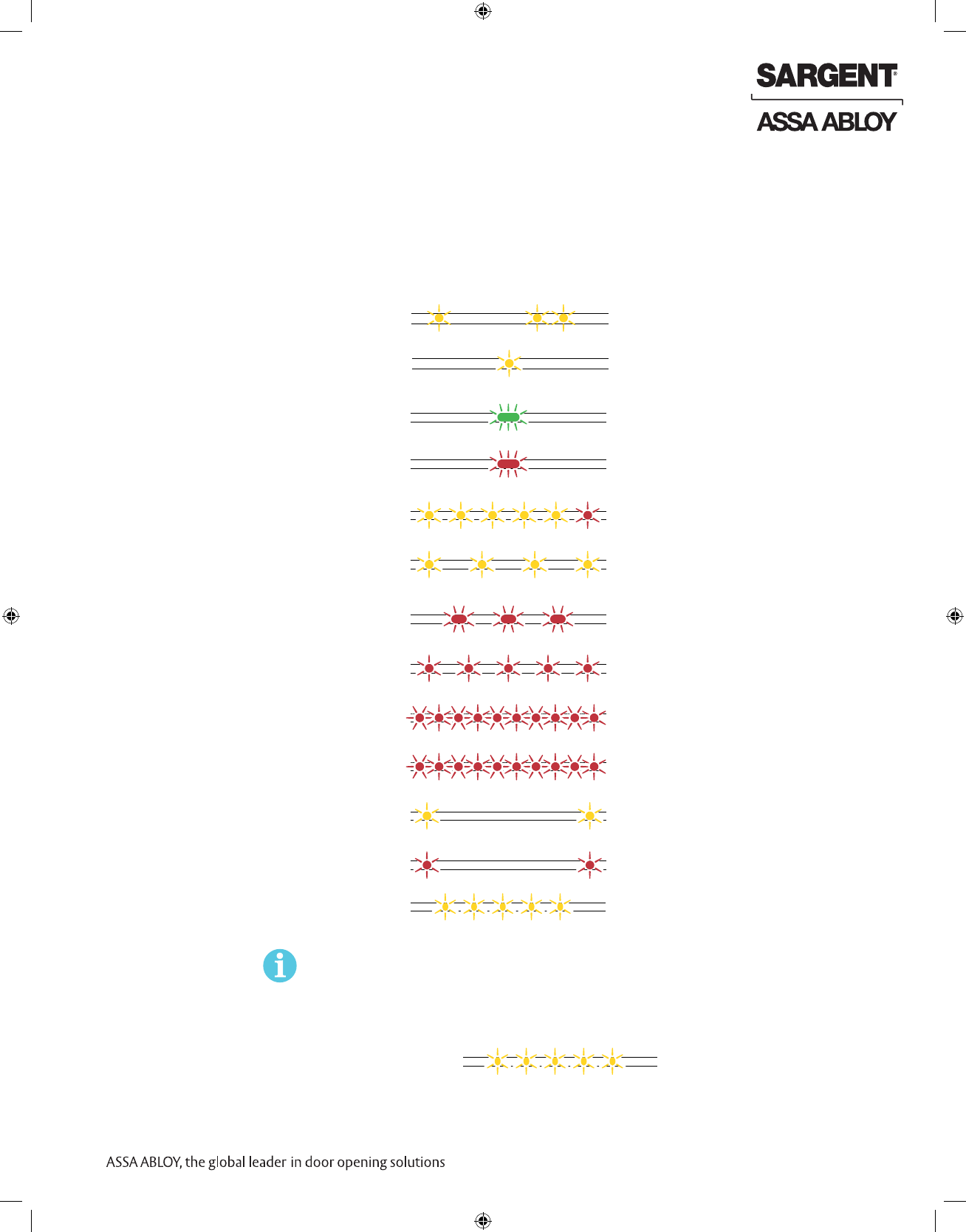
1)
Lock LED indications
The lock has three LEDs. They support an optical scheme with red, yellow and green.
The indication scheme is described by the figures below:
Figure 4. Lock normal operation LED
indication
One yellow flash after card, two
flashes before PIN (.125 second)
Card + PIN access
(configurable)
Access granted, One green flash
(1 sec.)
EAC offline or online
Access denied, One red flash
(1 sec.)
EAC online
Force closed in remote Five yellow flashes and
open/office mode one red flash (.25 second)
Busy blink, com hub
busy with other locks
Continuous yellow flashes
(.25 seconds every second)
Access denied, Three red flashes
(.5 second each)
EAC offline
Lock mechanism is Continuous red flashes
blocked when closing (.125 seconds every 1 sec.)
Error in lock, Ten red flashes (.125 sec. each)
maintenance required (Repeated every 10 sec. if lock can’t close)
Ten red flashes (.125 sec. each)
repeated every 10 sec.
Tamper
Time to replace Continuous yellow flashes
(.25 seconds every 5 sec.)
the battery
Battery reached end
of life, lock disabled
Continuous red flashes
(.25 seconds every 5 sec.)
1) When the lock mechanism is blocked (lock jammed) the lever must be turned to
release the lock mechanism.
Some special LED indication schemes are used during lock maintenance actions:
Figure 5. Lock hub normal
operation LED indication
One yellow flash (.25 second)
Card access
(configurable)
Enter PIN
EAC response
time
V3 USB cable detection
action occurred
Five yellow flashes
(.25 second each)
Enter configuration Five yellow flashes
(.125 second each)
mode
22 1-800-810-WIRE • www.sargentlock.com • A8189B
Copyright © 2016, Sargent Manufacturing Company, an ASSA ABLOY Group company. All rights reserved.
Reproductions in whole or in part without express written permission of Sargent Manufacturing Company is prohibited.
07/31/16
IN100 Cylindrical Lock
Lock Self-Test LED indication
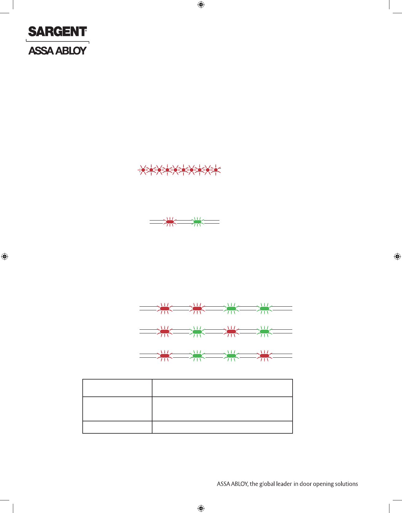
After replacing batteries, a Power on Self Test (POST) is performed. The result is indicated using
a series of red and green LED flashes as described by the figures below.
8.3.1 Battery not fully charged
8.3.2 Test pass
1 red (1s) + 1 green (1s), Power on self-test passed, see table below.
Error in lock, Ten red flashes (.125 sec. each)
maintenance required (Repeated every 10 sec. if lock can’t close)
LED indication after power up/replacement of the battery
Figure 6. Lock POST LED
indication
8.3.3 Test fail
1 red (1s) + 3 blinks (500ms, green or red), at least one test failed (red), see table below.
FATAL ERROR
CABLE ERROR
MECHANICAL ERROR
FATAL ERROR Tests core functionality. MCUs, memory and
internal communication, etc.
CABLE ERROR Tests communication between the different
parts in the system, i.e. different boards
connected with a wire.
MECHANICAL ERROR Test related to moving parts of the lock.
1 sec 0.5 sec 0.5 sec 0.5 sec
One red, one green flash
POST Successful (1 second)
If a fatal error is detected the lock will enter an Error state and continuously indicating fatal error
and will not read cards nor unlock.
Error in lock is an indication -10 quick (125ms) red blinks, that either new batteries are not at the
right voltage or a backward battery has been installed; battery not fully charged; energy counter
not reset or no Power on self-test done.


SARGENT Manufacturing
100 Sargent Drive
New Haven, CT 06511 USA
800-810-WIRE (9473) • www.sargentlock.com
Founded in the early 1800s, SARGENT® is a market leader in locksets, cylinders, door closers, exit devices,
electro-mechanical products and access control systems for new construction, renovation, and replacement applications.
The company’s customer base includes commercial construction, institutional, and industrial markets.
Copyright © 2016, Sargent Manufacturing Company, an ASSA ABLOY Group company. All rights reserved.
Reproduction in whole or in part without the express written permission of Sargent Manufacturing Company is prohibited.
ASSA ABLOY is the global leader in door opening solutions, dedicated to
satisfying end-user needs for security, safety and convenience. A8189B - 07/16