ASSALOY SCYMCA1 Aperio V3 iN100 RF Module User Manual FM404 IN100 Bored Instr
ASSA ABLOY Inc. Aperio V3 iN100 RF Module FM404 IN100 Bored Instr
UserManual.wiki
>
ASSALOY
>
SCYMCA1 User Manual
>
User Manual - FM404 IN100 Bored Instr
Contents
1.
User Manual - A8190B IN100 (V3) Bored
2.
User Manual - A8190B IN100 (V3) Mortise
3.
User Manual - FM403 IN100 Mortise Instr
4.
User Manual - FM404 IN100 Bored Instr
5.
MANUAL
6.
MANUAL - MODULE INTEGRATION
User Manual - FM404 IN100 Bored Instr
Navigation menu
Upload a User Manual
Namespaces
Wiki Guide
HTML
PDF
Info
Views
User Manual
Discussion / Help
Navigation
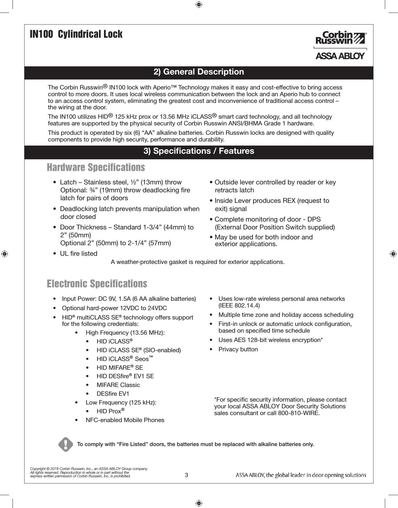
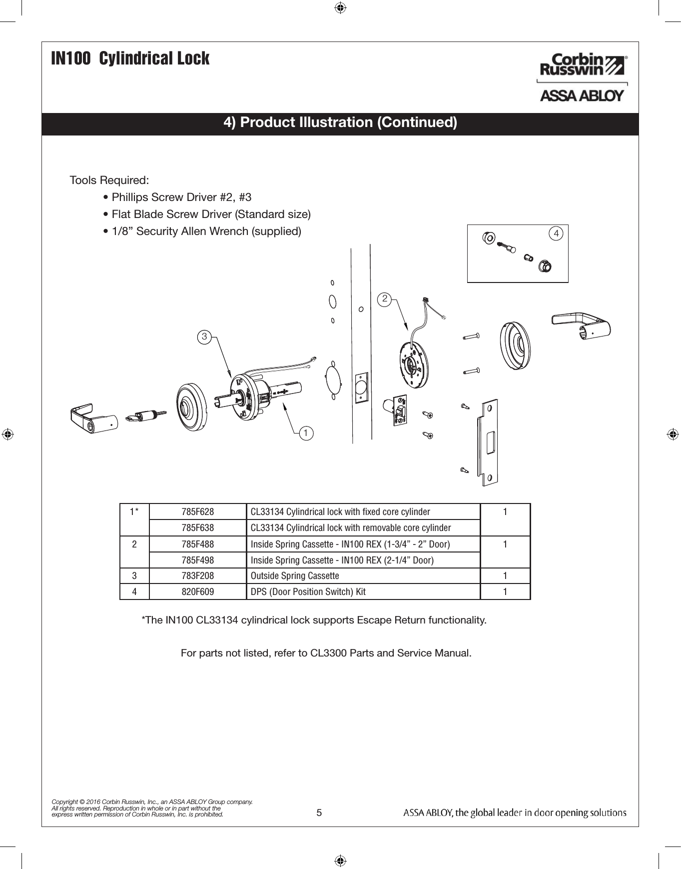
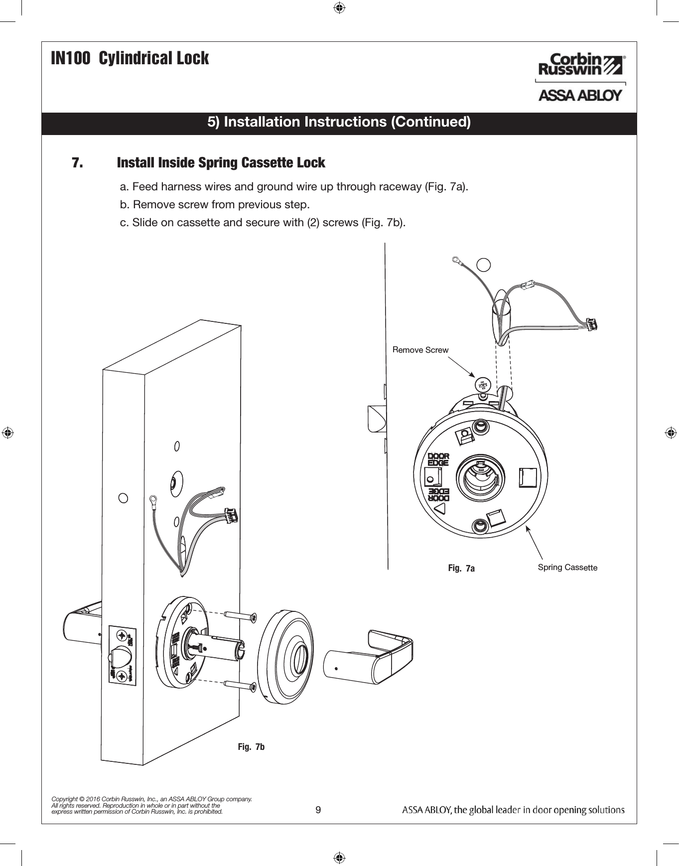
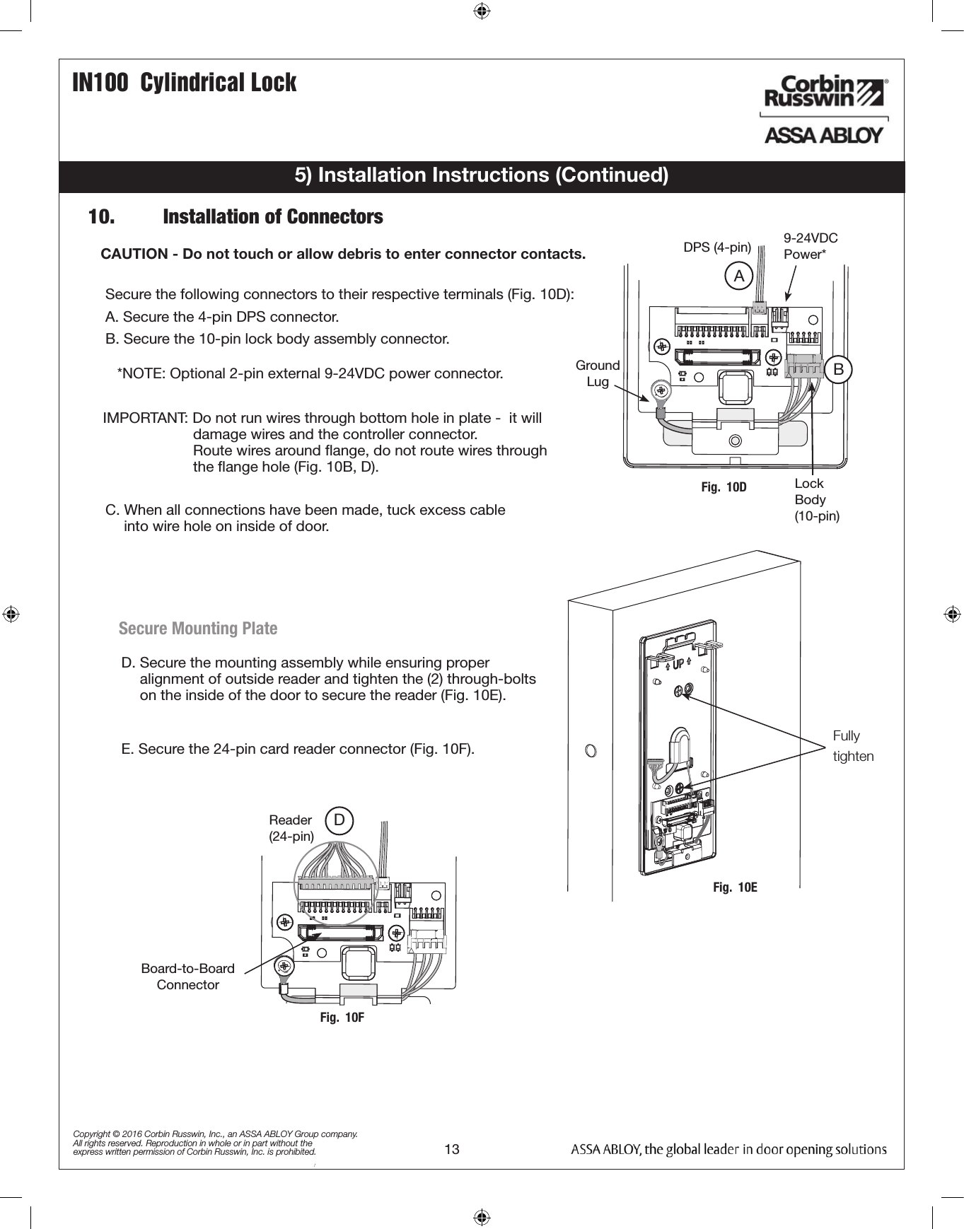
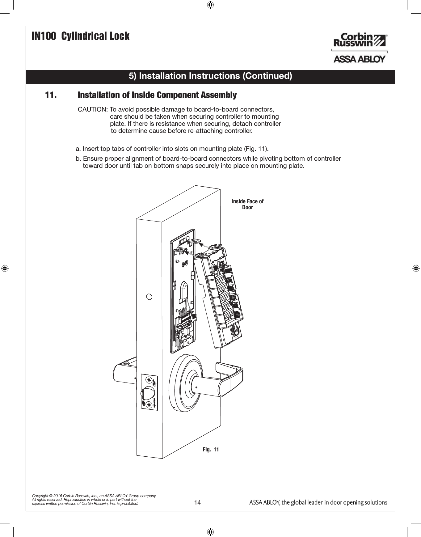
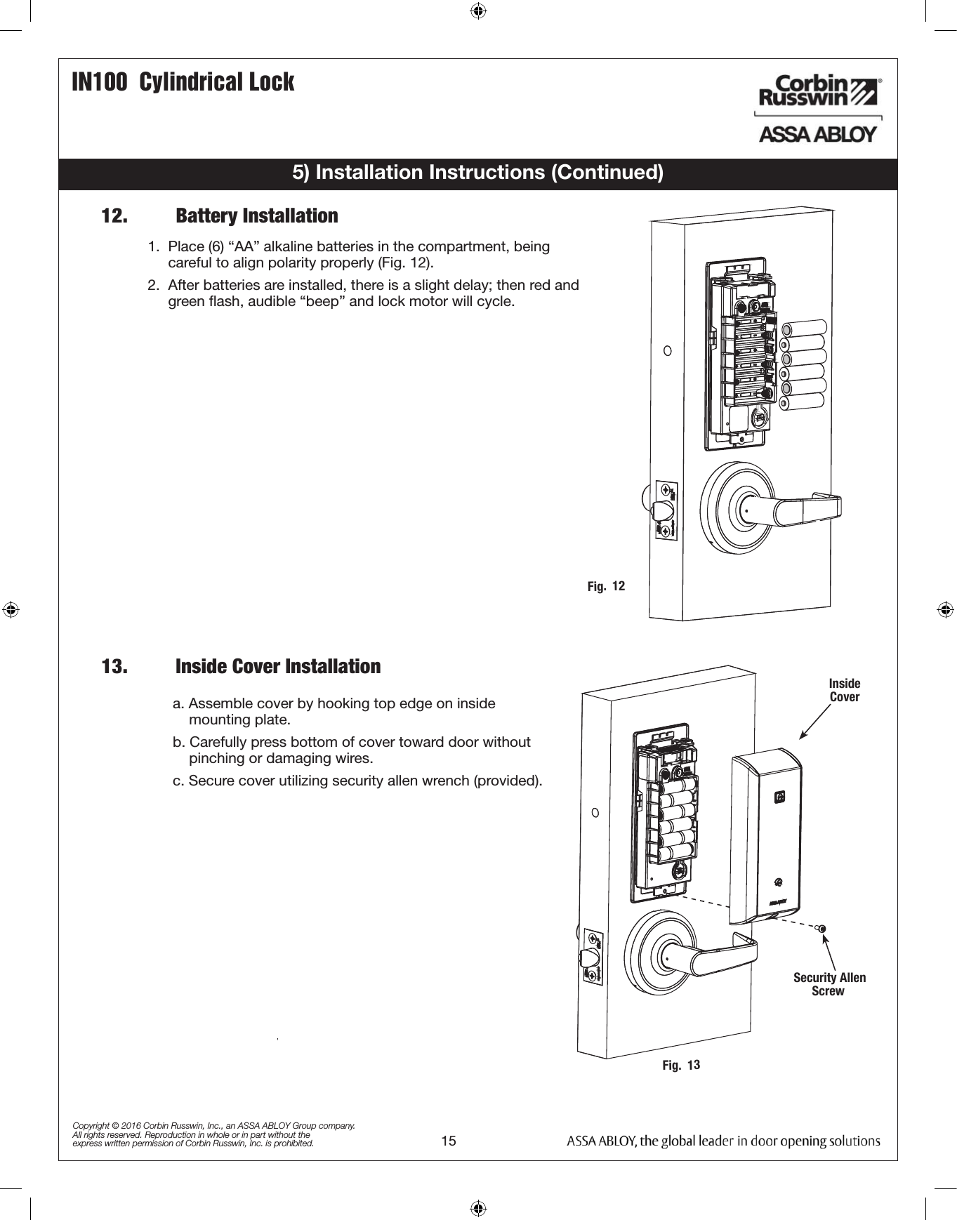
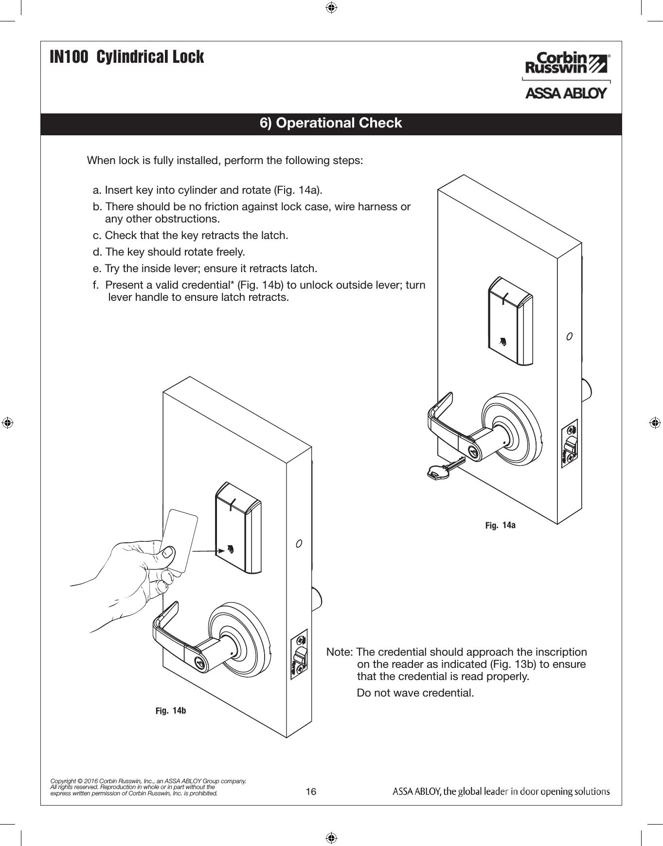
![4IN100 Cylindrical LockCopyright © 2016 Corbin Russwin, Inc., an ASSA ABLOY Group company. All rights reserved. Reproduction in whole or in part without the express written permission of Corbin Russwin, Inc. is prohibited.4) Product Illustration15432Reader ModuleITEM PART NUMBER/ORDER STRING DESCRIPTION COLOR/TRIM QTY1 IN-100-EM01CL33134-IP-B HID iCLASS®, HID iCLASS SE® (SIO-enabled), HID iCLASS® Seos™, HID MIFARE® SE, HID DESfire® EV1 SE, HID Prox®, NFC-enabled mobile phones Black 1IN-100-EM01CL33134-IP-W HID iCLASS®, HID iCLASS SE® (SIO-enabled), HID iCLASS® Seos™, HID MIFARE® SE, HID DESfire® EV1 SE, HID Prox®, NFC-enabled mobile phonesWhite 1IN-100-EM01CL33134-IP-MB-[finish]* HID iCLASS®, HID iCLASS SE® (SIO-enabled), HID iCLASS® Seos™, HID MIFARE® SE, HID DESfire® EV1 SE, HID Prox®, NFC-enabled mobile phonesBlack with metal trim 1IN-100-EM01CL33134-IP-MW-[finish]* HID iCLASS®, HID iCLASS SE® (SIO-enabled), HID iCLASS® Seos™, HID MIFARE® SE, HID DESfire® EV1 SE, HID Prox®, NFC-enabled mobile phonesWhite with metal trim 1IN-100-EM01CL33134-IPS-B All credentials supported by the IP option plus MIFARE Classic and DESfire EV1 Black 1IN-100-EM01CL33134-IPS-W All credentials supported by the IP option plus MIFARE Classic and DESfire EV1 White 1IN-100-EM01CL33134-IPS-MB-[finish]* All credentials supported by the IP option plus MIFARE Classic and DESfire EV1 Black with metal trim 1IN-100-EM01CL33134-IPS-MW-[finish]* All credentials supported by the IP option plus MIFARE Classic and DESfire EV1 White with metal trim 12 820F558 Inside Mounting Kit (mounting plate & hardware) 13 820F549 IN100 Controller 14 N/A AA battery 65 820F489 Inside Escutcheon Black 1820F499 Inside Escutcheon White820F525 FIN* Inside Escutcheon Black with metal trim820F535 FIN* Inside Escutcheon White with metal trim6 FM356 Field prep template (not shown) 17 T31203 Door manufacturers template (not shown) 1-- FM404 Instructions (this manual) 1* Specify finish](https://usermanual.wiki/ASSALOY/SCYMCA1.User-Manual-FM404-IN100-Bored-Instr/User-Guide-3061070-Page-4.png)