ASSALOY SCYPROX2 Harmony H2 Series Lock User Manual FCC Part 15
ASSA ABLOY Inc. Harmony H2 Series Lock FCC Part 15
ASSALOY >
Contents
- 1. Users Manual Bored and Exits
- 2. Users Manual Mortise
Users Manual Bored and Exits

5015 B.U. Bowman Drive Buford, GA 30518 USA Voice: 770-831-8048 Fax: 770-831-8598
Certification Exhibit
FCC ID: U4A-SCYPROX2
IC: 6982A-SCYPROX2
FCC Rule Part: 15.225
IC Radio Standards Specification: RSS-210
ACS Report Number: 09-0176 - 15C
Manufacturer: Assa Abloy, Inc.
Model: Bored/Exits, Mortise
Manual – Bored/Exits
A8029A
06/09
Copyright © 2009, Sargent Manufacturing Company, an ASSA ABLOY Group company.
All rights reserved. Reproduction in whole or in part without the express written
permission of Sargent Manufacturing Company is prohibited.
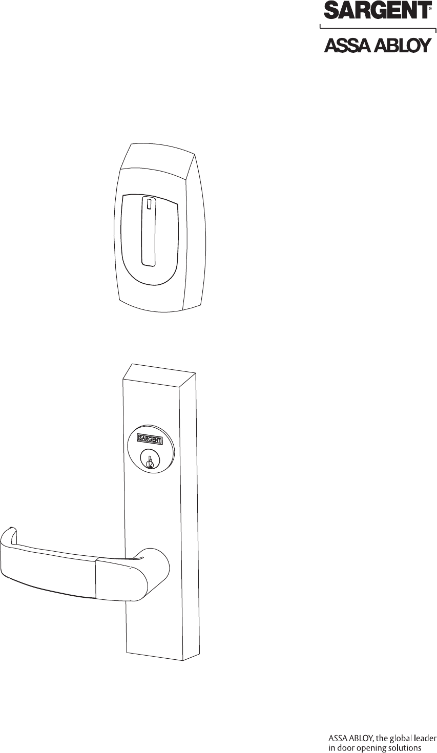
Installation Instructions
Harmony Series H2
8600, 8800, 8900 Exits
Copyright © 2009 Sargent Manufacturing Company, an ASSA ABLOY Group company. All rights reserved.
Reproductions in whole or in part without express written permission of Sargent Manufacturing Company is prohibited.
06/30/09
1
2
3
4
5
6
7
Table of Contents
Warning ...................................................................................2
General Description .................................................................3
Hardware Specifications .........................................................3
Electronics Specifications .......................................................3
H2 8600 Concealed Vertical Rod (CVR) Exit Device ................4
H2 8800 Rim Exit Device ........................................................11
H2 8900 Mortise Exit Device ..................................................17
Wiring Diagrams ....................................................................24
Mechanical Operational Check .............................................28
Electrical Operational Check .................................................28
8
9
10
A8029A • 800-810-WIRE (9473) • www.sargentlock.com 2
This device complies with Part 15 of the FCC Rules. Operation is subject to the following two conditions: (1) this device
may not cause harmful interference, and (2) this device must accept any interference received, including interference that
may cause undesired operation.
Note: This equipment has been tested and found to comply with the limits for a Class B digital device, pursuant to Part
15 of the FCC Rules. These limits are designed to provide reasonable protection against harmful interference in a resi-
dential installation.
This equipment generates, uses and can radiate radio frequency energy and if not installed and used in accordance with
the instructions, may cause harmful interference to radio communications. However, there is no guarantee that the inter-
ference will not occur in a particular installation. If this equipment does cause harmful interference to radio or television
reception, which can be determined by turning the equipment off and on, the user is encouraged to try to correct the
interference by one or more of the following measures:
• Reorient or relocate the receiving antenna
• Increase the separation between the equipment and receiver
• Connect the equipment into an outlet on a circuit different from that to which the receiver is connected
• Consult the dealer or an experienced technician for help
The term “IC:” before the radio certication number only signies that Industry Canada technical specications were
met. This Class B digital apparatus meets all requirements of the Canadian Interference Causing Equipment Regulations.
Operation is subject to the following two conditions: (1) this device may not cause harmful interference, and (2)
this device must accept any interference received, including interference that may cause undesired operation.
Cet appareillage numérique de la classe B répond à toutes les exigences de l’interférence canadienne causant des
règlements d’équipement. L’opération est sujette aux deux conditions suivantes: (1) ce dispositif peut ne pas causer
l’interférence nocive, et (2) ce dispositif doit accepter n’importe quelle interférence reçue, y compris l’interférence qui
peut causer l’opération peu désirée.
Warning: Changes or modications to this unit not expressly approved by the party
responsible for compliance could void the user’s authority to operate the equipment.
Warning
1
Observe precautions for handling electrostatic sensitive devices.
!
06/30/09 Copyright © 2009 Sargent Manufacturing Company, an ASSA ABLOY Group company. All rights reserved.
Reproductions in whole or in part without express written permission of Sargent Manufacturing Company is prohibited.
A8029A • 800-810-WIRE (9473) • www.sargentlock.com 3
Electronics Specifications
General Description
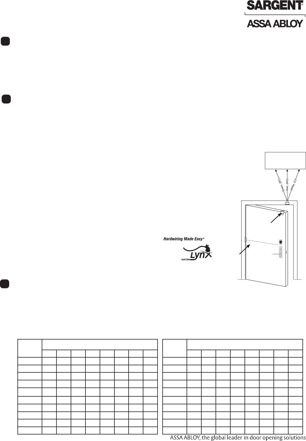
The SARGENT Harmony H2 series exit devices (8600, 8800, 8900) are designed to interface with existing Wiegand
Electronic Access Control (EAC) panels. The reader requires 12 or 24VDC for power and is compatible with HID
iCLASS® 13.56MHz technology. The Harmony series technology is backed by SARGENT Grade 1 mechanical hardware.
All exits include RX (request to exit) monitoring in the rail and an external Door Position Switch (DPS) for door position
monitoring. Harmony is available as 12VDC or 24VDC solenoid operated ET trim. Weatherseal gaskets are also included
for exterior door applications. The Harmony H2 iCLASS reader provides visual and audible indicators of lock state
(locked/unlocked).
Hardware Specifications
All Harmony Exit Devices
• Certied ANSI/BHMA A156.3 Grade 1
• Push bar retracts latch from inside, allowing free egress
• Request-to-Exit (REX) Switch activated by pushing rail
• Outside lever controlled by any 13.56MHz HID
iCLASS Wiegand credential
• Fire rated devices available
• UL Listed
• Exit devices furnished for 1-3/4” doors
• Fail safe or fail secure available
• Door Position Switch (DPS, part #3287) supplied to
allow for monitoring
• 12VDC/24VDC solenoid-operated ET trim
• EAC Panel wiring to door must be shielded with a
drain. Drain terminated at EAC Panel controller
Harmony 8600 Series Concealed Vertical Rod (CVR)
• Cylinder override available for 8600 CVR with 106
Series Auxiliary Control
• The AFF is 41” for Standard Applications; when a 100
Series Auxiliary Control is used, 38” AFF is
recommended to meet local accessibility standards
12VDC System
• Reader Draw = 125mA
• 12VDC Solenoid Draw = 500mA
• Total Current Draw = 625mA
4
2
Wire Gauge Charts
Total
One-Way
Length of
Wire Run (ft)
Load Current @ 12VDC
1/4A 1/2A 3/4A 1A 1-1/4A 1-1/2A 2A 3A
100 20 18 16 14 14 12 12 10
150 18 16 14 12 12 12 10 —
200 16 14 12 12 10 10 — —
250 16 14 12 10 10 10 — —
300 16 12 12 10 10 — — —
400 14 12 10 — — — — —
500 14 10 10 — — — — —
7501210——————
1,000 10 — — — — — — —
1,500 10 — — — — — — —
Total
One-Way
Length of
Wire Run (ft)
Load Current @ 24VDC
1/4A 1/2A 3/4A 1A 1-1/4A 1-1/2A 2A 3A
100 24 20 18 18 16 16 14 12
150 22 18 16 16 14 14 12 10
200 20 18 16 14 14 12 12 10
250 18 16 14 14 12 12 12 10
300 18 16 14 12 12 12 10 —
400 18 14 12 12 10 10 — —
500 16 14 12 10 10 — — —
750 14 12 10 10 — — — —
1,000 14 10 10 — — — — —
1,500 12 10 — — — — — —
24VDC System
• Reader Draw = 125mA
• 24VDC Solenoid Draw = 250mA
• Total Current Draw = 375mA
Harmony 8800 Series Rim
• Cylinder override available
• Accepts all SARGENT rim cylinders (75/76 functions)
• Key retracts latch (75/76 functions)
• Latch – 3/4” throw, stainless steel
Harmony 8900 Series
Mortise
• Cylinder override available
• Accepts all
SARGENT mortise
cylinders (75/76 functions)
• Key retracts latch
(75/76 functions)
• Latch – 3/4” throw,
anti-friction, brass
3
Harmony Series H2 Exit Devices
Weigand Access
Control System
3287 Door
Position Switch
Harmony Series H2
McKinney
Electronic
Transfer
Hinge
Copyright © 2009 Sargent Manufacturing Company, an ASSA ABLOY Group company. All rights reserved.
Reproductions in whole or in part without express written permission of Sargent Manufacturing Company is prohibited.
06/30/09
A8029A • 800-810-WIRE (9473) • www.sargentlock.com4
1
2
2
2
3
4
5
6
7
8
9
10
99
11
12
13A
13B
114
1
16
15
1
17
18
17
Installation Instructions For Harmony Series H2 8600
Concealed Vertical Rod (CVR) Exit Device
5
Tools Required
• Phillips screw driver (standard size)
• Flat blade screw driver (standard)
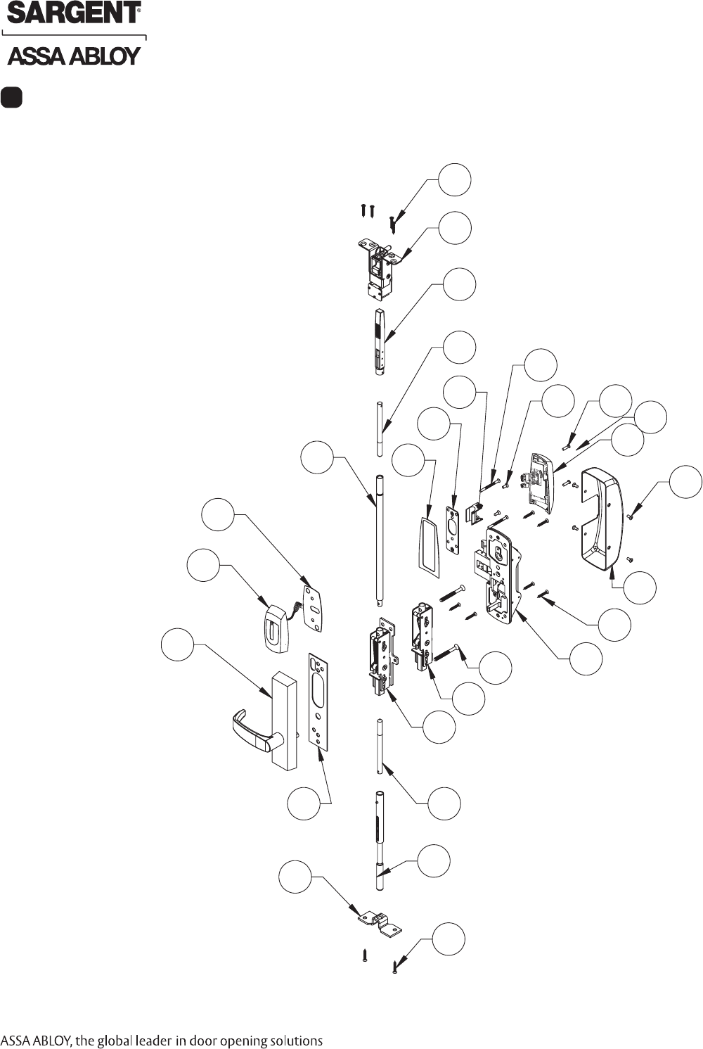
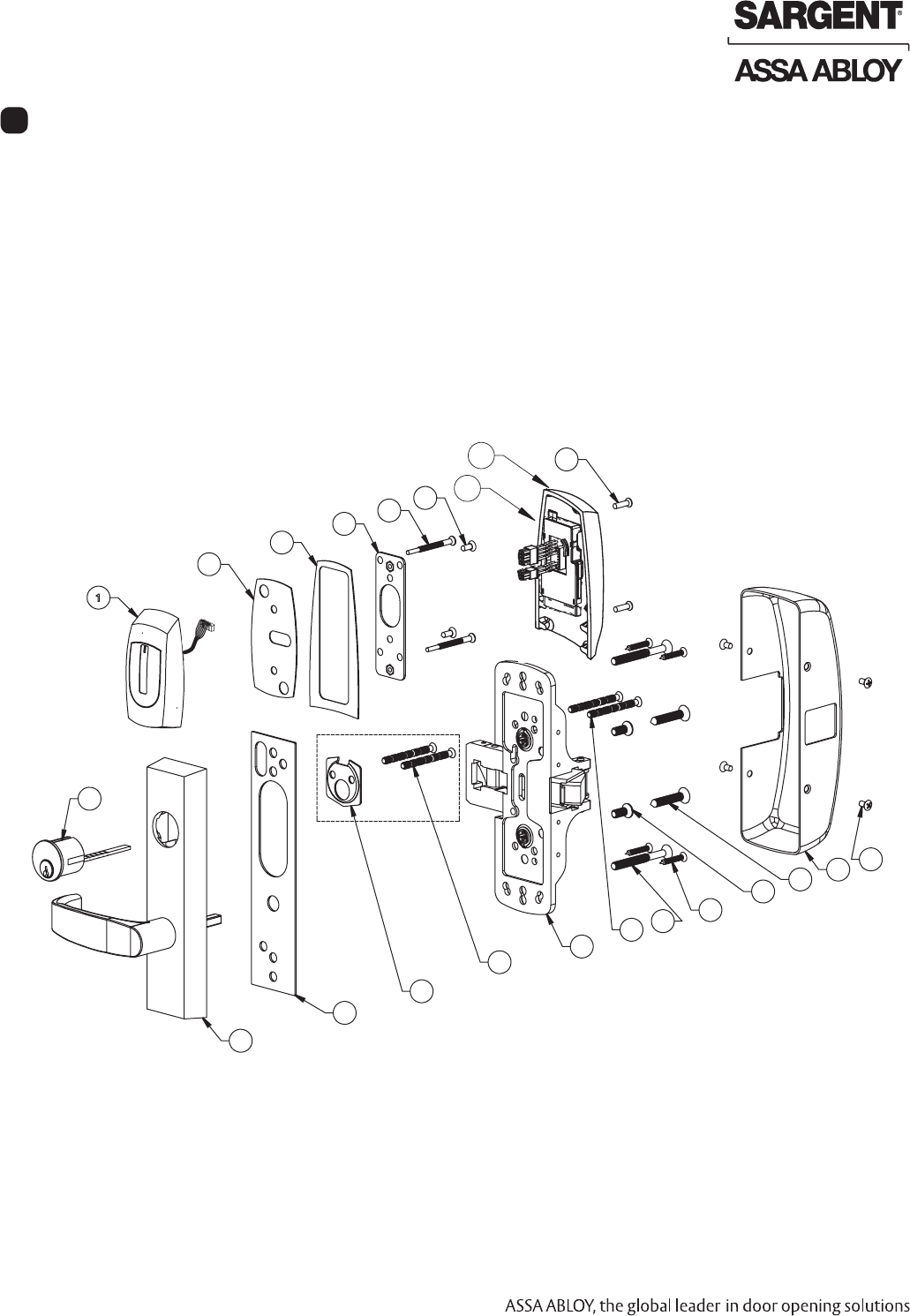
Harmony Series H2 8600 Exits
Parts Breakdown
10
10A
06/30/09 Copyright © 2009 Sargent Manufacturing Company, an ASSA ABLOY Group company. All rights reserved.
Reproductions in whole or in part without express written permission of Sargent Manufacturing Company is prohibited.
A8029A • 800-810-WIRE (9473) • www.sargentlock.com 5
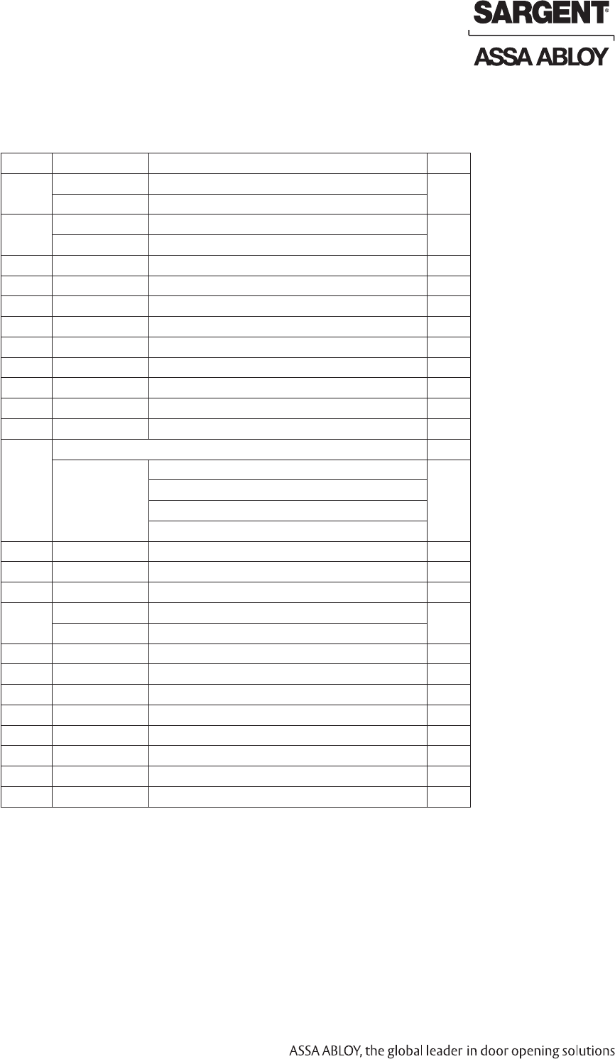
ITEM PART # Description Req.
1 68-3577 Chassis Wood Door (WD) Screw Pack 1
68-3905 Chassis Metal Door (MD) Screw Pack (not shown)
2 68-7057 WD 8600 Top Assembly 1
68-7060 MD/AD 8600 Top Assembly (not shown)
3 94-0212 Aux Control Rod Adapter 1
4 52-4038 Outside Harmony Escutcheon Assembly 1
5 52-0792 Outside Harmony Gasket 1
6 52-0793 Inside Harmony Gasket 1
7 52-5219 Harmony Inside Escutcheon Mounting Plate 1
8 52-0801 Wire Guide 1
9 52-5236 Screw Pack (Escutcheon) 1
10 68-1581 Inside Harmony Escutcheon 1
10A 52-4036 H2 Controller Assembly 1
11 *Harmony Trim is Ordered as "N1"
N1-773-4 ETL12V Fail Safe 1
N1-773-4 ETL 24V Fail Safe
N1-774-4 ETL12V Fail Secure
N1-774-4 ETL 24V Fail Secure
12 52-0263 ET Trim Gasket 1
13A 68-3859 WD Inner Case Assembly 1
13B 68-5067 MD/AD Inner Case Assembly 1
14 68-7241 8600 Chassis LHRB 1
68-7242 8600 Chassis RHRB (not shown)
15 68-0407 Chassis Cover 1
16 68-3905 Screw Pack (Rail and Chassis Cover) 1
17 68-0888 MD/WD Bottom Case Assembly 1
17 68-0037 AD Bottom Case Assembly 1
18 3287 DPS Door Position Switch (not shown) 1
19 A8029 Installation Instructions (not shown) 1
20 4621 MD/AD Door Manufacturer Template (not shown) 1
21 4622 Wood Door Manufacturer Template (not shown) 1
Parts Breakdown For Harmony Series H2 8600 (Continued)
Shipment Contents
Harmony Series H2 8600 Exits
How to Specify ET Trim
How to order without an exit device.
Specify: 7 for 700 Series ET, Function, Sufx, Lever, Finish and handing (e.g., 775-8 ETL x 26D x RHRB).
Note: Sufx requirements are based on type of device to be used:
• -8 sufx is required for 8800, 8500, NB8700, PP, PR and SP8700 devices, except with these functions: 04, 10, 16, 40 and 44.
• -6 sufx is required for all PP, PR, SP, LP, LR and LS devices.
• -4 sufx is required for all 8400, WD, MD and AD 8600 devices.
• No sufx is necessary for all 8900, 8300, 8700 with bottom rod and 8800, 8500, NB8700, PP, PR & SP8700 devices
with these functions: 04, 10, 16, 40 and 44.
Copyright © 2009 Sargent Manufacturing Company, an ASSA ABLOY Group company. All rights reserved.
Reproductions in whole or in part without express written permission of Sargent Manufacturing Company is prohibited.
06/30/09
A8029A • 800-810-WIRE (9473) • www.sargentlock.com6
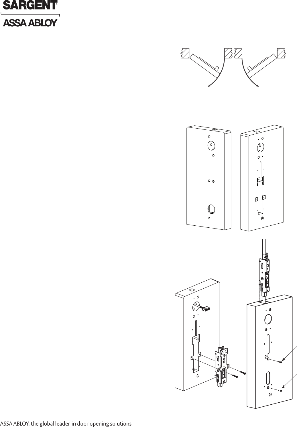
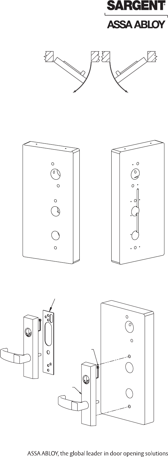
Step #1 – Prepare Door
A. Verify Hand and Bevel of Door
• Check hand of door. Exit Device may be handed.
• Door should be tted and hung.
• Verify box label for size of exit device, function and hand.
B. Door Preparation
Prepare door according to appropriate template. If necessary,
refer to website, www.intelligentopenings.com:
• Metal door (MD/AD): A7002
- Templates: 4621 and 4445
• Wood door (WD): A3937
- Templates: 4622 and 4431
Note: Instruction examples show wood door installation.
For metal/aluminum doors, route cables inside door.
#10-24 x 1/2”
Left Hand
Reverse
LHR
Outside
Inside
Right Hand
Reverse
RHR
#10-24 x 3/8”
Fig. 1A
Harmony Series H2 8600 Exits
Wood Door Shown
Fig. 1B
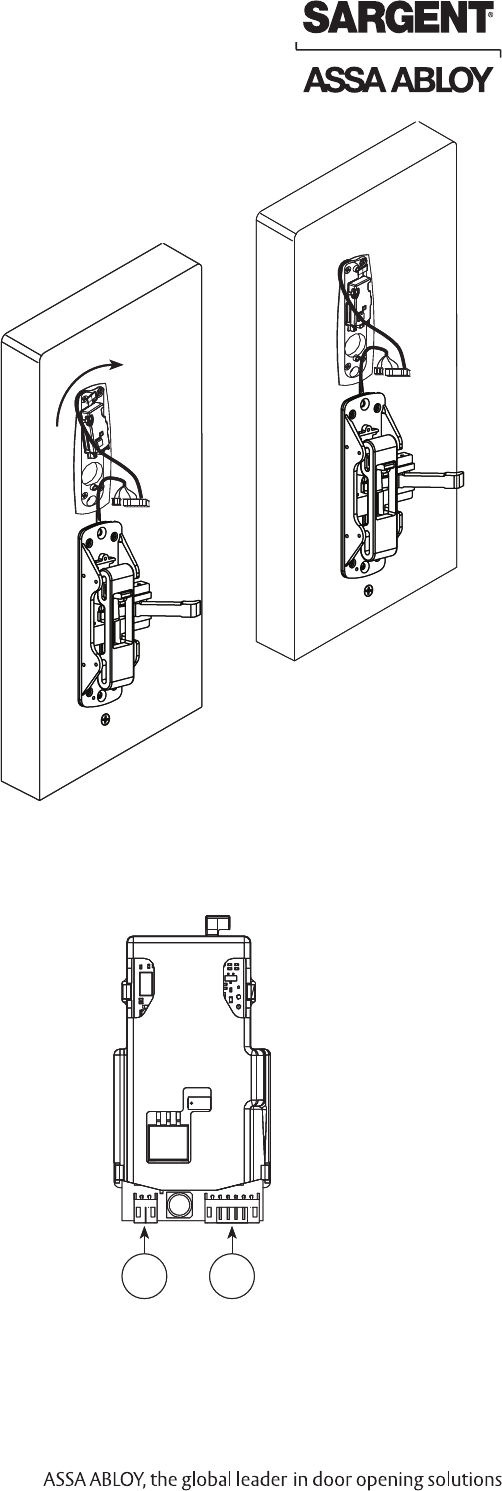
Step #2 - Inner Case Assembly Installation
A. Wood Door (WD)
Install the inner case assembly with (2) #12 x 1” Phillips
athead screw (Fig. 2A).
B. Metal Door (MD/AD)
1. Assemble rods to inner case.
2. Slide rod assembly into door and secure with #10-24 x 3/8”
screw for top inner case assembly and #10-24 x 1/2” screw
for bottom inner case assembly (Fig. 2B).
Fig. 2A
Fig. 2B
06/30/09 Copyright © 2009 Sargent Manufacturing Company, an ASSA ABLOY Group company. All rights reserved.
Reproductions in whole or in part without express written permission of Sargent Manufacturing Company is prohibited.
A8029A • 800-810-WIRE (9473) • www.sargentlock.com 7
8600 Installation Instructions (Continued)
B. Chassis
1. Position chassis carefully onto the inner chassis assembly from the
inside of the door. Be careful not to pinch wire harness.
2. Fasten the chassis to door using (4) #12 x 1” Phillips
athead screws (Fig. 3C).
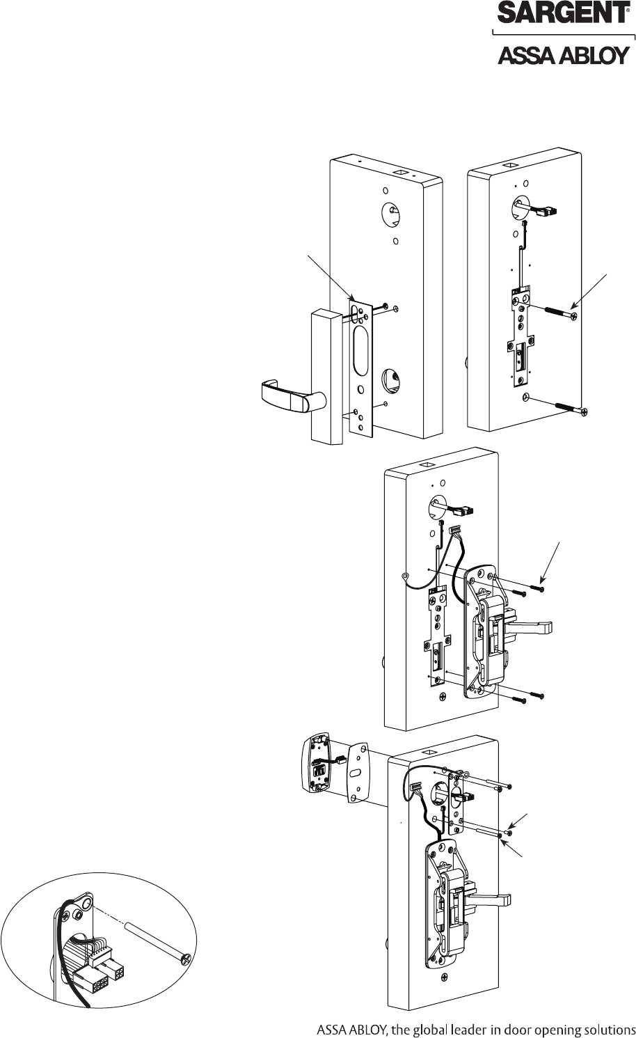
Step #3 – Install Outside Exit Trim (ET) and Chassis
A. Outside Trim
1. For exterior applications, use ET gasket (52-0263)
to seal ET escutcheon and outside door surface (Fig. 3A).
2. Route ET wire harness through inner chassis
assembly:
- For wood doors: Route wire harness in cutout.
- For metal doors: Route wire harness through
access hole.
3. Mount ET trim to inner chassis assembly using
(2) # 1/2 -20 x 2-3/8” at head machine screws.
ET spindle engages inside the inner chassis
assembly (Fig. 3B).
Fig. 3A
Harmony Series H2 8600 Exits
Fig. 3B
#10-24 x 3/8”
Gasket
Fig. 3B
(4) #12 x 1” Phillips
Flathead Screws
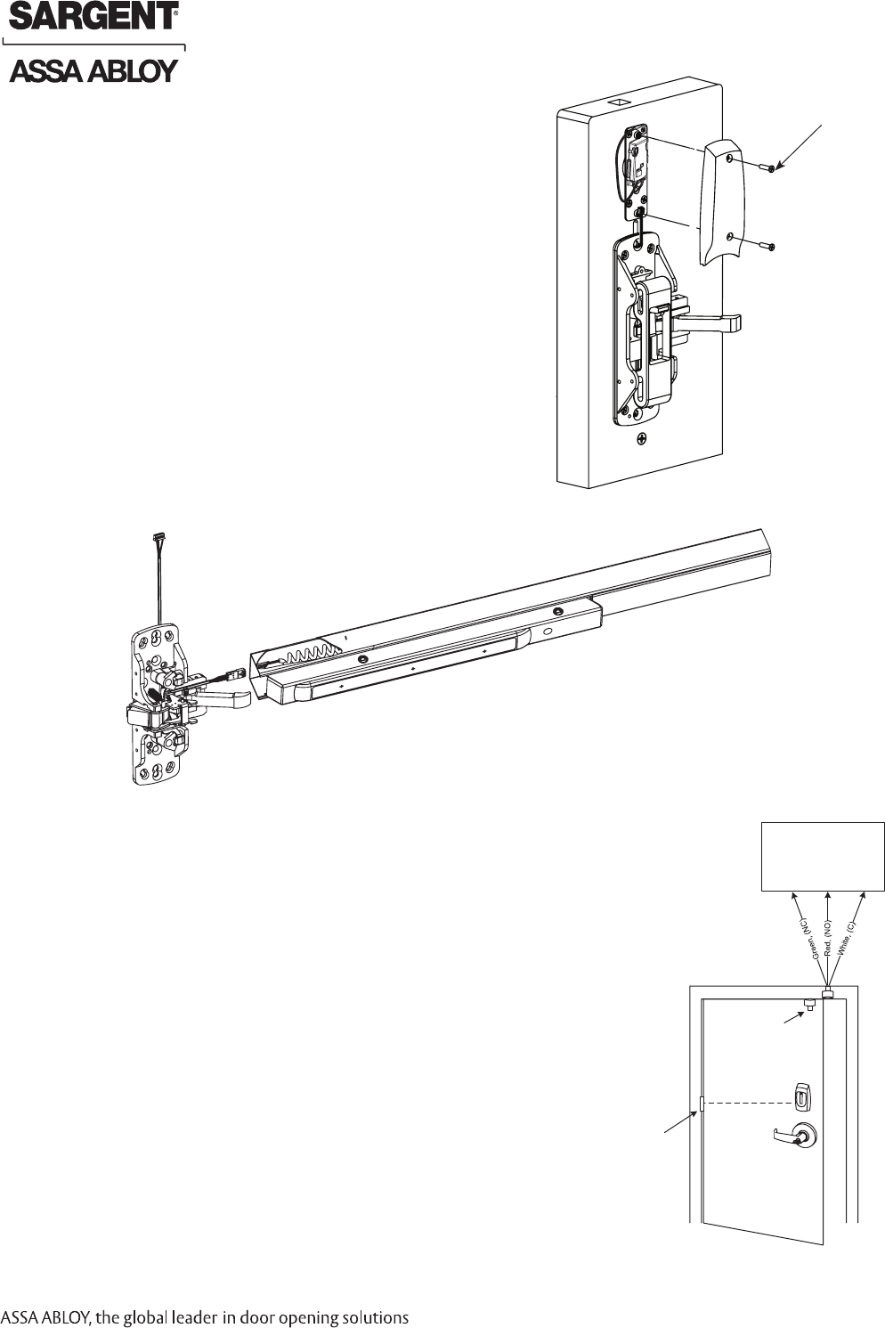
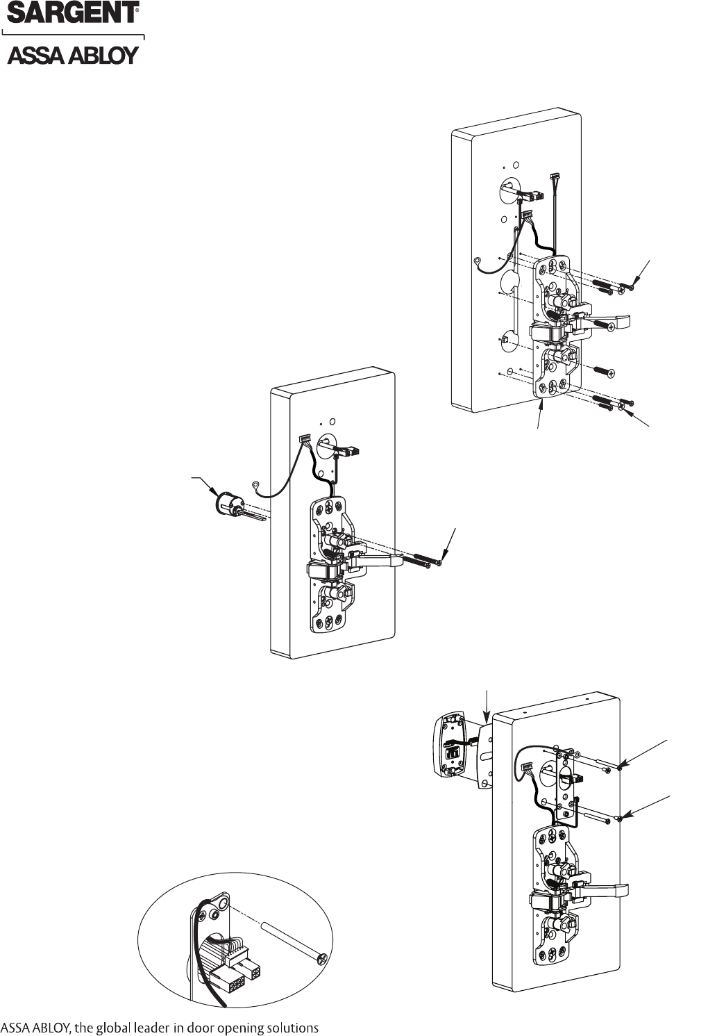
Step #4 – Attach Ground Wire and Install Outside
Escutcheon and Inside Mounting Plate
1. Connect pin 5 green/yellow ground wire ring terminal
to top right screw (Fig. 4A and 4B).
2. Secure the mounting plate with (2) #8 x 1/2”
self-tapping screws (Fig. 4A).
3. Feed the reader cable connector located
on the back of the outside escutcheon
from the outside of door through door.
4. Securely tighten the outside escutcheon with
through-bolts using (2) #8-32 x 2” Phillips at
head screws through the mounting plate. #8-32 X 2”
#8-32 X 1/2”
Fig. 4A
Fig. 3C
Fig. 4B
Inside of Door
Copyright © 2009 Sargent Manufacturing Company, an ASSA ABLOY Group company. All rights reserved.
Reproductions in whole or in part without express written permission of Sargent Manufacturing Company is prohibited.
06/30/09
A8029A • 800-810-WIRE (9473) • www.sargentlock.com8
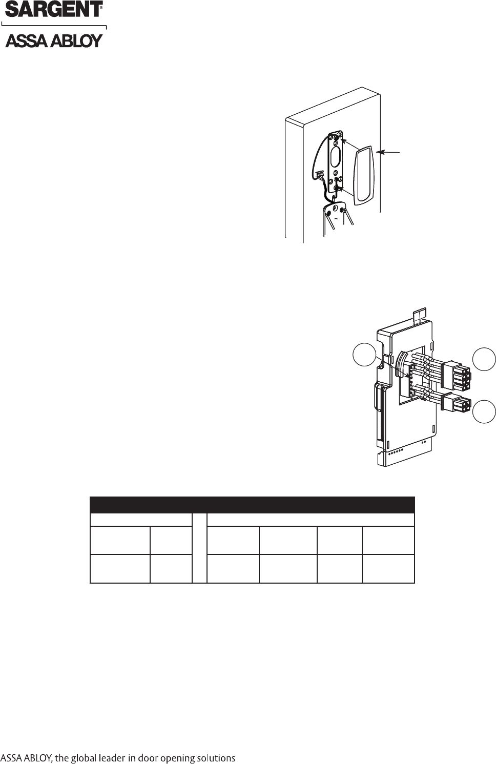
Step #5 – Install Gasket
Add Gasket (if necessary):
Remember the inside gasket must be used
when installing in an outdoor application.
Remove backing and place gasket
on door (Fig. 5A).
Inside of Door
Gasket required
for exterior door
applications.
Fig. 5A
Step #6 – Connect ElectroLynx
1. Connect P5 (7 Pin Connector) from reader board
to J5 on interior escutcheon PCB assembly (Fig. 6A).
2. Connect ElectroLynx harness (4 and 8-pin) from door harness
to ElectroLynx harness on interior PCB assembly (Fig. 6A).
NOTES:
Neatly fold the wires onto themselves and into the remaining
space to prevent pinching wires when mounting escutcheon.
Do not tuck extra mortise lock body wires back inside the lock
body cylinder hole.
Connectors go on only one way.
Do not offset connector and be sure they are completely seated. Fig. 6A
J1
J2
To ElectroLynx
Harness
J5
From Reader
Board P5 to J5
PCB Layout - Wire Assignments - ElectroLynx Assembly (Molex)
J2 J1
1-Violet Lock DC Neg
(Solenoid, neg)
3 - Pink
NOT USED
1- Black
PWR NEG
3-White
Wiegand DATA 1
5-Orange
RX (N/O)
7-Brown
EGND
2-Gray, Lock DC Pos
(Solenoid, pos)
4-Tan
NOT USED
2-Red
PWR POS
4-Green
Wiegand DATA 0
6-Blue
RX (COM)
8-Yellow
LED
Harmony Series H2 8600 Exits
Inside of Door
Gasket required
for exterior door
applications.
Fig. 5A
Fig. 6A
J1
J2
To ElectroLynx
Harness
J5
From Reader
Board P5 to J5
06/30/09 Copyright © 2009 Sargent Manufacturing Company, an ASSA ABLOY Group company. All rights reserved.
Reproductions in whole or in part without express written permission of Sargent Manufacturing Company is prohibited.
A8029A • 800-810-WIRE (9473) • www.sargentlock.com 9
Fig. 7A
Fig. 7B
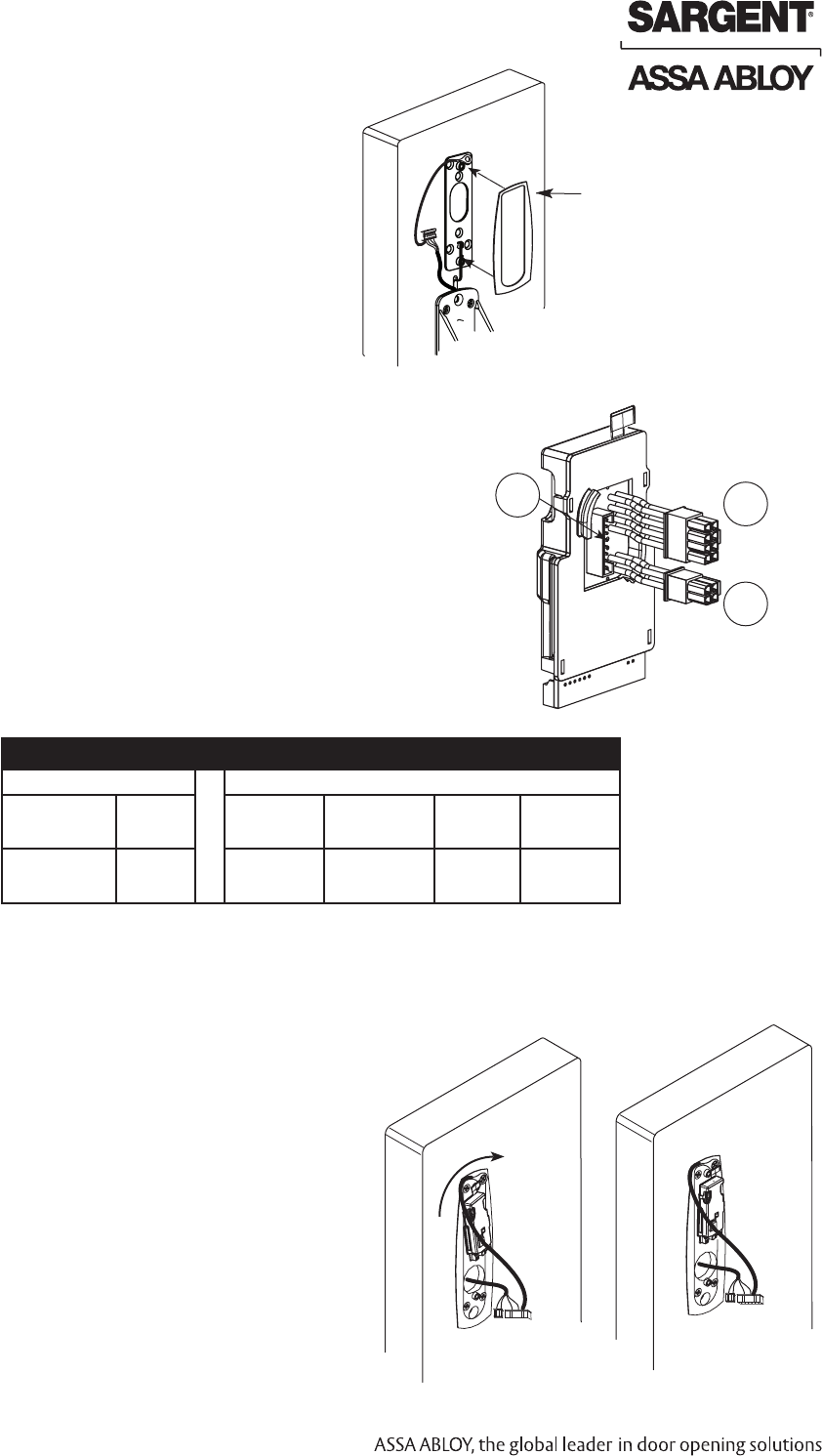
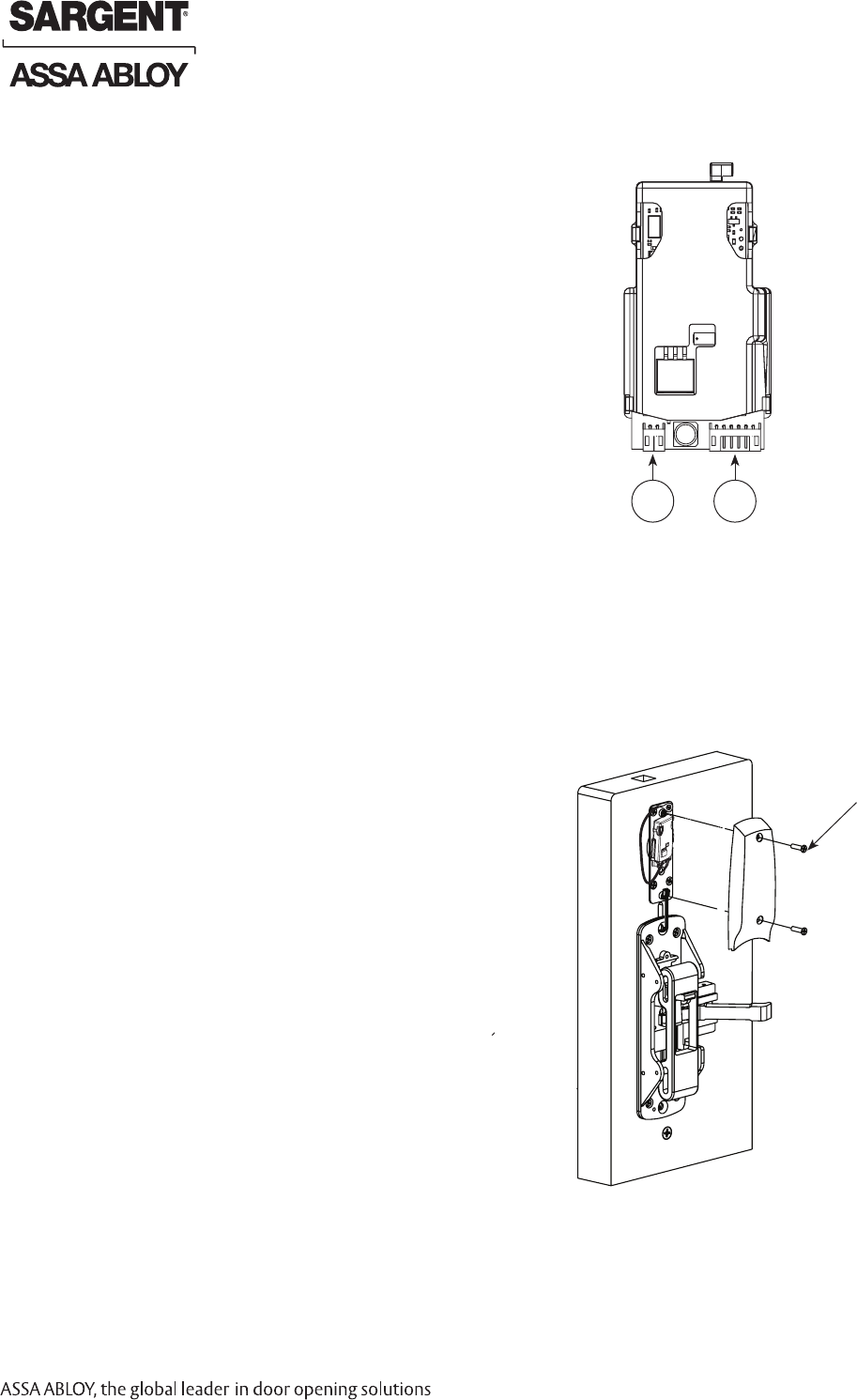
Step #8 – Attach Connectors (Exterior PCB Assembly)
1. Connect P3 (2-pin connector) from lock body
to J3 on module (Fig. 8A).
2. Connect P4 (6-pin connector) from lock body
to J4 on module (Fig. 8A).
From Lock
Body P3 to J3 From Lock
Body P4 to J4
Fig. 8A
J4 J3
Inside of Door
Rotate Clockwise
Step #7 – Position Outside Wires
Please follow these steps prior to installing
inside escutcheon to prevent any damage
caused by pinching wires:
1. Once wires are arranged, position piece
at a rotated angle against the door, under
earth ground wire.
2. Press piece against door unwhile turning
clockwise (Fig. 7A).
3. Twist into place, perpendicular with door (Fig. 7B).
Fig. 7A
Fig. 7B
Harmony Series H2 8600 Exits
From Lock
Body P3 to J3 From Lock
Body P4 to J4
Fig. 8A
J4 J3
Inside of Door
Rotate Clockwise
Copyright © 2009 Sargent Manufacturing Company, an ASSA ABLOY Group company. All rights reserved.
Reproductions in whole or in part without express written permission of Sargent Manufacturing Company is prohibited.
06/30/09
A8029A • 800-810-WIRE (9473) • www.sargentlock.com10
Fig. 10A
Step #9 – Install Inside Escutcheon
1. Position inside gasket and escutcheon against door.
Verify that no wires are being pinched.
2. Mount inside escutcheon assembly to plate using
(2) #8-32 x 5/8" Phillips at head undercut
machine screws.
Step #10 – Install Rail Assembly
1. Retrieve harness from end of rail. Harness has limited travel
and can be damaged.
2. Attach harness to female connector on chassis.
3. Install rail and screws per exit device instructions.
Note: This view shows rim exit device version.
>> Continue to Section 9 for Wiring Diagrams to wire Device to EAC Panel. <<
Fig. 9A
Inside of Door
Harmony Series H2 8600 Exits
(2) #8-32 x 5/8” Phillips
Flat Head Under-cut
Machine Screws
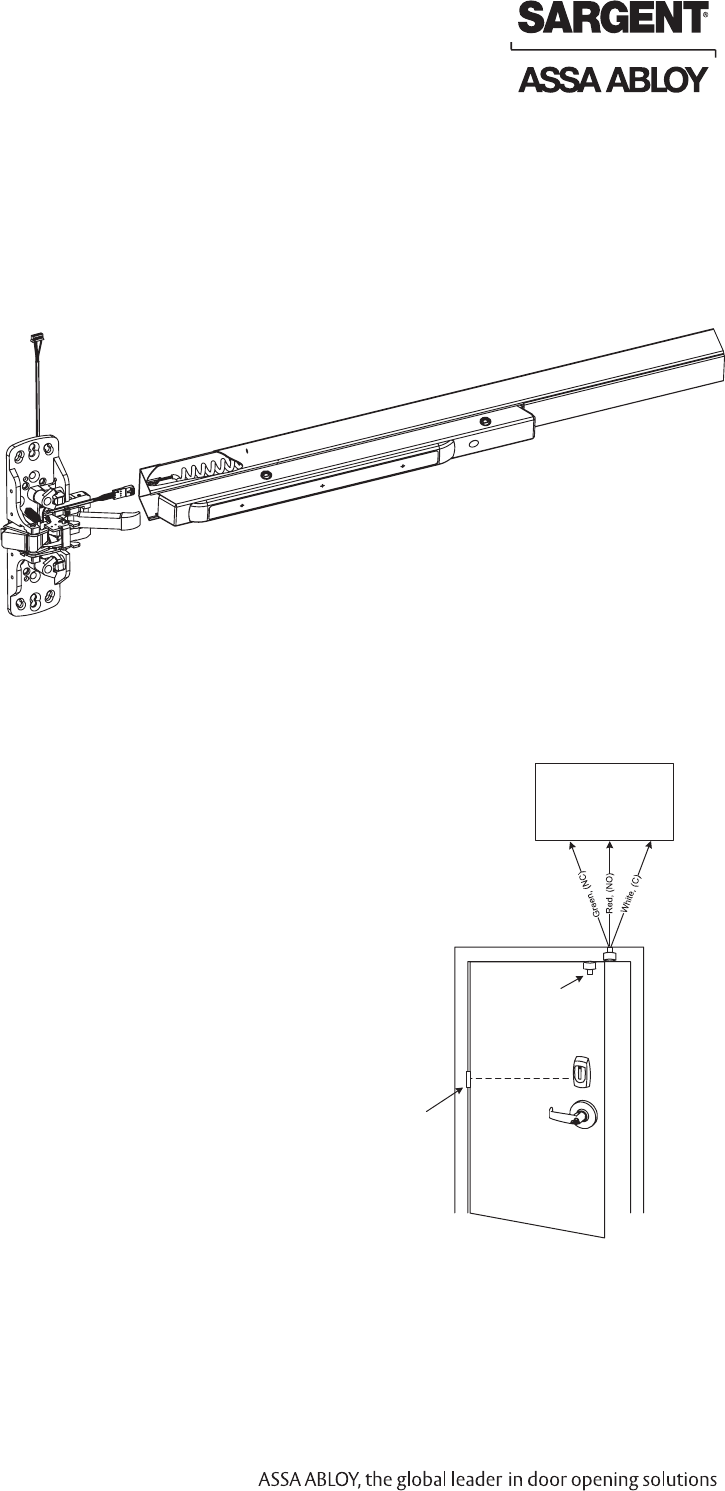
Step #11 - Concealed Door Position Switch Instructions (3287)
Use SARGENT 3287 Concealed Door Position Switch with this
Harmony H2 series product:
1. Install the 3287 Concealed Door Position Switch described in SARGENT
document A7448B.
2. Wire the 3287 Concealed Door Position Switch to the EAC door position Input.
3. Connect the common wire of the switch to the common input terminal of the EAC;
and the normally open wire of the switch to the normally open input
termnial of the EAC.
Fig. 11A
Wiegand Access
Control System
(Others)
McKinney
QC12 Hinge Harmony Series H2
3287 Door
Position Switch
Lock is 12VDC.
Optional 24VDC
lock is available.
06/30/09 Copyright © 2009 Sargent Manufacturing Company, an ASSA ABLOY Group company. All rights reserved.
Reproductions in whole or in part without express written permission of Sargent Manufacturing Company is prohibited.
A8029A • 800-810-WIRE (9473) • www.sargentlock.com 11
Tools Required
• Phillips screw driver (standard size)
• Flat blade screw driver (standard)
Installation Instructions For Harmony Series H2 8800 Rim Exit Device
7
5
5
2
3
4
10
6
5
11
12
13
14
15
10
9
1
9
9
9
8
7
Left Hand Reverse Door Shown
Parts Breakdown
Harmony Series H2 8800 Exits
6
6A
Copyright © 2009 Sargent Manufacturing Company, an ASSA ABLOY Group company. All rights reserved.
Reproductions in whole or in part without express written permission of Sargent Manufacturing Company is prohibited.
06/30/09
A8029A • 800-810-WIRE (9473) • www.sargentlock.com12
ITEM PART # Description Req.
1 52-4038 Outside Harmony Escutcheon Assembly 1
2 52-0792 Outside Weather Gasket 1
3 52-0793 Inside Weather Gasket 1
4 52-5219 Harmony Inside Escutcheon Mounting Plate 1
5 52-5236 Screw Pack (Escutcheon) 1
6 68-1581 Inside Escutcheon Assembly 1
6A 52-4036 H2 Controller Assembly 1
7 68-3905 Screw Pack (Rail and Chassis Cover) 1
8 68-0406 Chassis Cover 1
9 68-3922 Screw Pack (Chassis) 1
10 13-0074 Cylinder Connecting Screws 2
11 68-7255 8800 Chassis Assembly (Standard)
1
68-7256 8800 Chassis Assembly (12-)
68-5836 8800 Chassis Assembly (GL)
68-5837 8800 Chassis Assembly (12-, GL)
12 13-0086 Cylinder back Plate Used with non-Sargent Cylinders) 1
13 52-0263 ET Trim Gasket 1
14 *Harmony Trim is Ordered as "N1" 1
N1-773-ET 12V Fail Safe Without Cylinder
N1-773-ET 24V Fail Safe Without Cylinder
N1-774-ET 12V Fail Secure Without Cylinder
N1-774-ET 24V Fail Secure Without Cylinder
N1-775-ET 12V Fail Safe Without Cylinder
N1-775-ET 24V Fail Safe Without Cylinder
N1-776-ET 12V Fail Secure Without Cylinder
N1-776-ET 24V Fail Secure Without Cylinder
15 -- Reference Harmony Series Catalog for Available Cylinders 1
16 3287 DPS Door Position Switch (not shown) 1
17 A8029 Installation Instructions (not shown) 1
18 A7883 Field Template (not shown) 1
19 4615 Manufacturer Template (not shown) 1
Parts Breakdown For Harmony Series H2 8800 (Continued)
Shipment Contents
How to Specify ET Trim
How to order without an exit device.
Specify: 7 for 700 Series ET, Function, Sufx, Lever, Finish and handing (e.g., 775-8 ETL x 26D x RHRB).
Note: Sufx requirements are based on type of device to be used:
• -8 sufx is required for 8800, 8500, NB8700, PP, PR and SP8700 devices, except with these functions: 04, 10, 16, 40 and 44.
• -6 sufx is required for all PP, PR, SP, LP, LR and LS devices.
• -4 sufx is required for all 8400, WD, MD and AD 8600 devices.
• No sufx is necessary for all 8900, 8300, 8700 with bottom rod and 8800, 8500, NB8700, PP, PR & SP8700 devices
with these functions: 04, 10, 16, 40 and 44.
Harmony Series H2 8800 Exits
06/30/09 Copyright © 2009 Sargent Manufacturing Company, an ASSA ABLOY Group company. All rights reserved.
Reproductions in whole or in part without express written permission of Sargent Manufacturing Company is prohibited.
A8029A • 800-810-WIRE (9473) • www.sargentlock.com 13
Step #1 – Door Preparation
A. Verify Hand and Bevel of Door
• Check hand of door. Exit Device may be handed.
• Door should be tted and hung.
• Verify box label for size of exit device, function and hand.
B. Door Preparation
Prepare door according to appropriate template. If necessary,
refer to website, www.intelligentopenings.com:
• Field prep template: A7883
• Manufacturer template: 4615
• Reference exit device templates: 4415, and 4530
Note: Instruction examples show wood door
installation. For metal doors, route cables inside door.
Left Hand
Reverse
LHR
Outside
Inside
Right Hand
Reverse
RHR
Fig. 1A
Wood Door Shown
Fig. 1B
Fig. 2B Detail
Fig. 2A
Wire Harness
ET Gasket
ET Control
Step #2 – Outside Trim (Exit Trim, ET) Installation
1. For exterior applications, use ET gasket (52-0263) to seal between
ET escutcheon and outside door surface (Fig. 2B).
2. Route ET wire harness in cutout for wood doors
and through access hole for metal doors (Fig. 2A).
3. Hold ET control onto door.
Harmony Series H2 8800 Exits
Copyright © 2009 Sargent Manufacturing Company, an ASSA ABLOY Group company. All rights reserved.
Reproductions in whole or in part without express written permission of Sargent Manufacturing Company is prohibited.
06/30/09
A8029A • 800-810-WIRE (9473) • www.sargentlock.com14
8800 Installation Instructions (Continued)
Step #3 – Mounting Chassis
1. Position chassis carefully, not to pinch wire harness.
2. ET spindle will engage the lower hub of chassis.
3. Cylinder tailpiece should engage upper hub of the chassis.
4. Though bolt chassis to ET with (2) 1/4 -20 x 2-3/8” at head
machine screws.
5. Using (4) #10 wood screws or #10-24 machine screws fasten
chassis to door.
Step #4 – Cylinder Installation
1. Position cylinder in ET control.
2. For non-Sargent cylinder ONLY:
Secure cylinder with cylinder
backplate using
(2) #12-24 x 1-7/8” screws.
3. Make sure ET harness is clear of
cylinder and cylinder tailpiece.
#12 x 1” Phillips Flat
Head Wood Screw
1/4 -20 x 2-3/8” Flat
Head Machine Screw
Exit Chassis
Inside of Door
#12-24 X 1-7/8” Screws
Cylinder
Inside of Door
Step #5 – Outside Escutcheon and Inside
Mounting Plate and Ground Wire Installation
1. Connect pin 5 green/yellow ground wire ring terminal to
top right screw (Fig. 5A and 5B).
1. Secure the mounting plate with (2) self-tapping screws (#8 x 1/2”).
2. Feed the reader cable connector located on the back of the outside
escutcheon from the outside of door through door.
3. Securely tighten the outside escutcheon with (2) through-bolts
(#8-32 x 2”) Phillips at head screws through the mounting plate.
Outside Gasket
#8-32 x 2” Phillips
Flat Head Screws
#8 x 1/2” Self-
Taping Screws
Fig. 3A
Fig. 4A
Fig. 5A
Inside of Door
Harmony Series H2 8800 Exits
Fig. 5B
06/30/09 Copyright © 2009 Sargent Manufacturing Company, an ASSA ABLOY Group company. All rights reserved.
Reproductions in whole or in part without express written permission of Sargent Manufacturing Company is prohibited.
A8029A • 800-810-WIRE (9473) • www.sargentlock.com 15
Please follow these steps prior to installing inside escutcheon
assembly to prevent any damage caused by pinching wires:
1. Align the ElectroLynx® connectors (8 and 4-pin) to one side of
the wire guide inside of the door prep. The reader connections
and excess wire are arranged on the other.
2. Connect the ElectroLynx® connectors (8 and 4-pin) and
establish their position inside of the door prep on
the proper side of the wire guide (Fig. 8A).
3. Neatly route the remaining wires onto themselves and into
the remaining space to prevent pinching wires when
mounting the escutcheon (Fig. 8B).
Step #8 – Outside Escutcheon and Wire Positioning
Step #6 – Install Gasket
Add Gasket (if necessary):
Remember the inside gasket must be used
when installing in an outdoor application.
Remove backing and place gasket
on door (Fig. 6A).
Inside of Door
Outside of Door
Fig. 8A Fig. 8B
Fig. 6A
Step #7 – Connect ElectroLynx
1. Connect P5 (7 Pin Connector) from reader board
to J5 on interior escutcheon PCB assembly (Fig. 7A).
2. Connect ElectroLynx harness (4 and 8-pin) from door harness
to ElectroLynx harness on interior PCB assembly (Fig. 7A).
NOTES:
Neatly fold the wires onto themselves and into the remaining
space to prevent pinching wires when mounting escutcheon.
Do not tuck extra mortise lock body wires back inside the lock
body cylinder hole.
Connectors go on only one way.
Do not offset connector and be sure they are completely seated. Fig. 7A
J1
J2
To ElectroLynx
Harness
J5
From Reader
Board P5 to J5
Harmony Series H2 8800 Exits
PCB Layout - Wire Assignments - ElectroLynx Assembly (Molex)
J2 J1
1-Violet Lock DC Neg
(Solenoid, neg)
3 - Pink
NOT USED
1- Black
PWR NEG
3-White
Wiegand DATA 1
5-Orange
RX (N/O)
7-Brown
EGND
2-Gray, Lock DC Pos
(Solenoid, pos)
4-Tan
NOT USED
2-Red
PWR POS
4-Green
Wiegand DATA 0
6-Blue
RX (COM)
8-Yellow
LED
Rotate Clockwise
Gasket required
for exterior door
applications.
Copyright © 2009 Sargent Manufacturing Company, an ASSA ABLOY Group company. All rights reserved.
Reproductions in whole or in part without express written permission of Sargent Manufacturing Company is prohibited.
06/30/09
A8029A • 800-810-WIRE (9473) • www.sargentlock.com16
Step #10 – Installation of Inside Escutcheon
1. Position inside gasket and escutcheon against door. Verify that no
wires are being pinched.
2. Mount inside escutcheon assembly to plate using (2) #8-32 x 5/8"
Phillips at head undercut machine screws. (2) #8-32 x 5/8” Phillips
Flat Head Under-cut
Machine Screws
Fig. 10A
Inside of Door
Harmony Series H2 8800 Exits
From Lock
Body P3 to J3 From Lock
Body P4 to J4
Fig. 9A
J4 J3
Step #9 – Connector Attachment
(Exterior PCB Assembly)
1. Connect P3 (2-pin connector) from lock body
to J3 on module (Fig. 9A).
2. Connect P4 (6-pin connector) from lock body
to J4 on module (Fig. 9A).
06/30/09 Copyright © 2009 Sargent Manufacturing Company, an ASSA ABLOY Group company. All rights reserved.
Reproductions in whole or in part without express written permission of Sargent Manufacturing Company is prohibited.
A8029A • 800-810-WIRE (9473) • www.sargentlock.com 17
Step #11 – Installation of Rail Assembly
1. Retrieve harness from end of rail. Harness has limited travel
and can be damaged.
2. Attach harness to female connector on chassis.
3. Install rail and screws per exit device instructions.
Note: This view shows rim exit device version
>> Continue to Section 9 for Wiring Diagrams to wire Device to EAC Panel. <<
Step #12 - Concealed Door Position Switch (3287) Instructions
Use SARGENT 3287 Concealed Door Position Switch with this
Harmony H2 series product:
1. Install the 3287 Concealed Door Position Switch described in SARGENT
document A7448B.
2. Wire the 3287 Concealed Door Position Switch to the EAC door position Input.
3. Connect the common wire of the switch to the common input terminal of the EAC;
and the normally open wire of the switch to the normally open input
termnial of the EAC.
Fig. 11A
Fig. 12A
Wiegand Access
Control System
(Others)
McKinney
QC12 Hinge Harmony Series H2
3287 Door
Position Switch
Lock is 12VDC.
Optional 24VDC
lock is available.
Copyright © 2009 Sargent Manufacturing Company, an ASSA ABLOY Group company. All rights reserved.
Reproductions in whole or in part without express written permission of Sargent Manufacturing Company is prohibited.
06/30/09
A8029A • 800-810-WIRE (9473) • www.sargentlock.com18
Tools Required
• Phillips screw driver (standard size)
• Flat blade screw driver (standard)
Installation Instructions For Harmony Series H2 8900 Mortise Exit Device
8
Left Hand Reverse Door Shown
Parts Breakdown
1
2
3
4
5
6
5
7
8
9
10
11
12
13 14
16
15
6
6A
Harmony Series H2 8900 Exits
06/30/09 Copyright © 2009 Sargent Manufacturing Company, an ASSA ABLOY Group company. All rights reserved.
Reproductions in whole or in part without express written permission of Sargent Manufacturing Company is prohibited.
A8029A • 800-810-WIRE (9473) • www.sargentlock.com 19
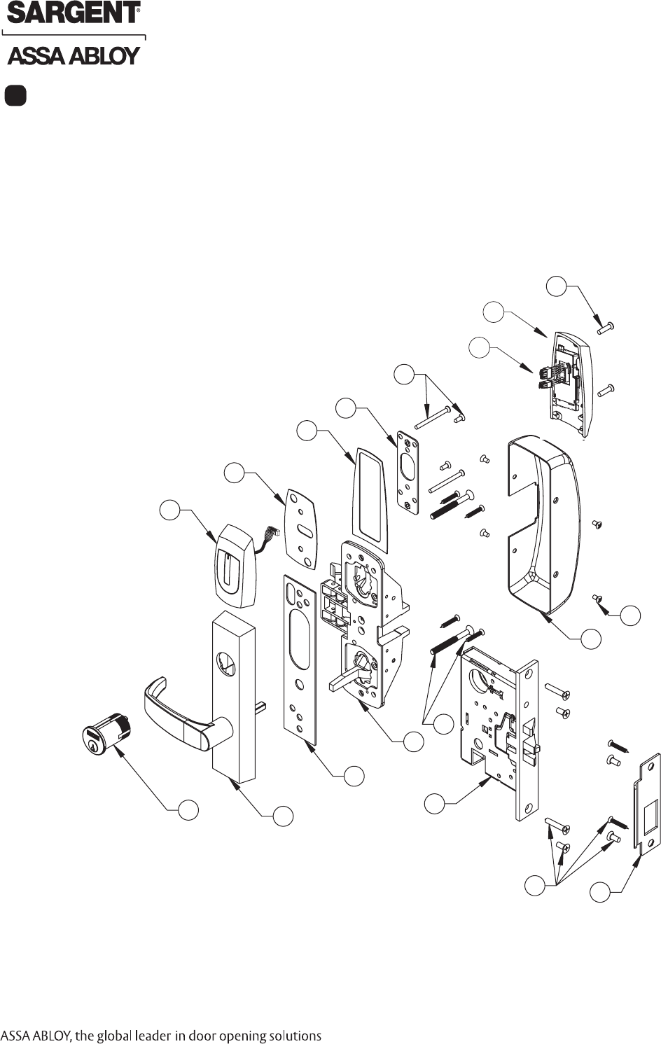
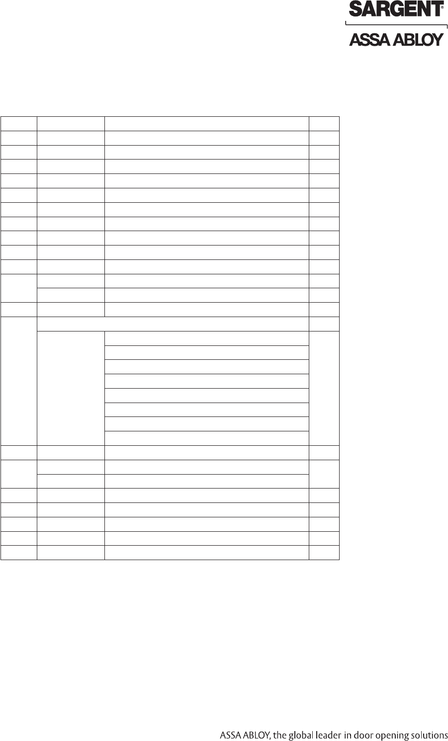
Parts Breakdown For Harmony Series H2 8900 (Continued)
ITEM PART # Description Req.
1 52-4038 Outside Harmony Escutcheon Assembly 1
2 52-0792 Outside Harmony Gasket 1
3 52-0793 Inside Harmony Gasket 1
4 52-5219 Harmony Inside Escutcheon Mounting Plate 1
5 52-5236 Screw Pack (Escutcheon) 1
6 68-1581 Inside Harmony Escutcheon Assembly 1
6A 52-4036 H2 Controller Assembly 1
7 68-3905 Screw Pack (Rail and Chassis Cover) 1
8 68-0407 Chassis Cover 1
9 68-3922 Screw Pack (Chassis) 1
10 68-7253 8900 Chassis Assembly LHRB 1
68-5754 8900 Chassis Assembly RHRB 1
11 52-0263 ET Trim Gasket 1
12 *Harmony Trim is Ordered as "N1"
N1-773-ET 12V Fail Safe Without Cylinder 1
N1-773-ET 24V Fail Safe Without Cylinder
N1-774-ET 12V Fail Secure Without Cylinder
N1-774-ET 24V Fail Secure Without Cylinder
N1-773-ET 12V Fail Safe With Cylinder
N1-773-ET 24V Fail Safe With Cylinder
N1-774-ET 12V Fail Secure With Cylinder
N1-774-ET 24V Fail Secure With Cylinder
13 -- Reference Harmony Series Catalog for Available Cylinders 1
14 915 8900 Lock Body Assembly LHRB 1
915 8900 Lock Body Assembly RHRB
15 99-2628 Screw Pack (Mortise Lock) 1
16 99-0131TAB Strike Pack (Specify Bevel and Lip Length) 1
17 A8029 Instruction Sheet (not shown) 1
18 A7948 Field Prep Template (not shown) 1
19 4613 Manufacturer Template (not shown) 1
Shipment Contents
How to Specify ET Trim
How to order without an exit device.
Specify: 7 for 700 Series ET, Function, Sufx, Lever, Finish and handing (e.g., 775-8 ETL x 26D x RHRB).
Note: Sufx requirements are based on type of device to be used:
• -8 sufx is required for 8800, 8500, NB8700, PP, PR and SP8700 devices, except with these functions: 04, 10, 16, 40 and 44.
• -6 sufx is required for all PP, PR, SP, LP, LR and LS devices.
• -4 sufx is required for all 8400, WD, MD and AD 8600 devices.
• No sufx is necessary for all 8900, 8300, 8700 with bottom rod and 8800, 8500, NB8700, PP, PR & SP8700 devices
with these functions: 04, 10, 16, 40 and 44.
Harmony Series H2 8900 Exits
Copyright © 2009 Sargent Manufacturing Company, an ASSA ABLOY Group company. All rights reserved.
Reproductions in whole or in part without express written permission of Sargent Manufacturing Company is prohibited.
06/30/09
A8029A • 800-810-WIRE (9473) • www.sargentlock.com20
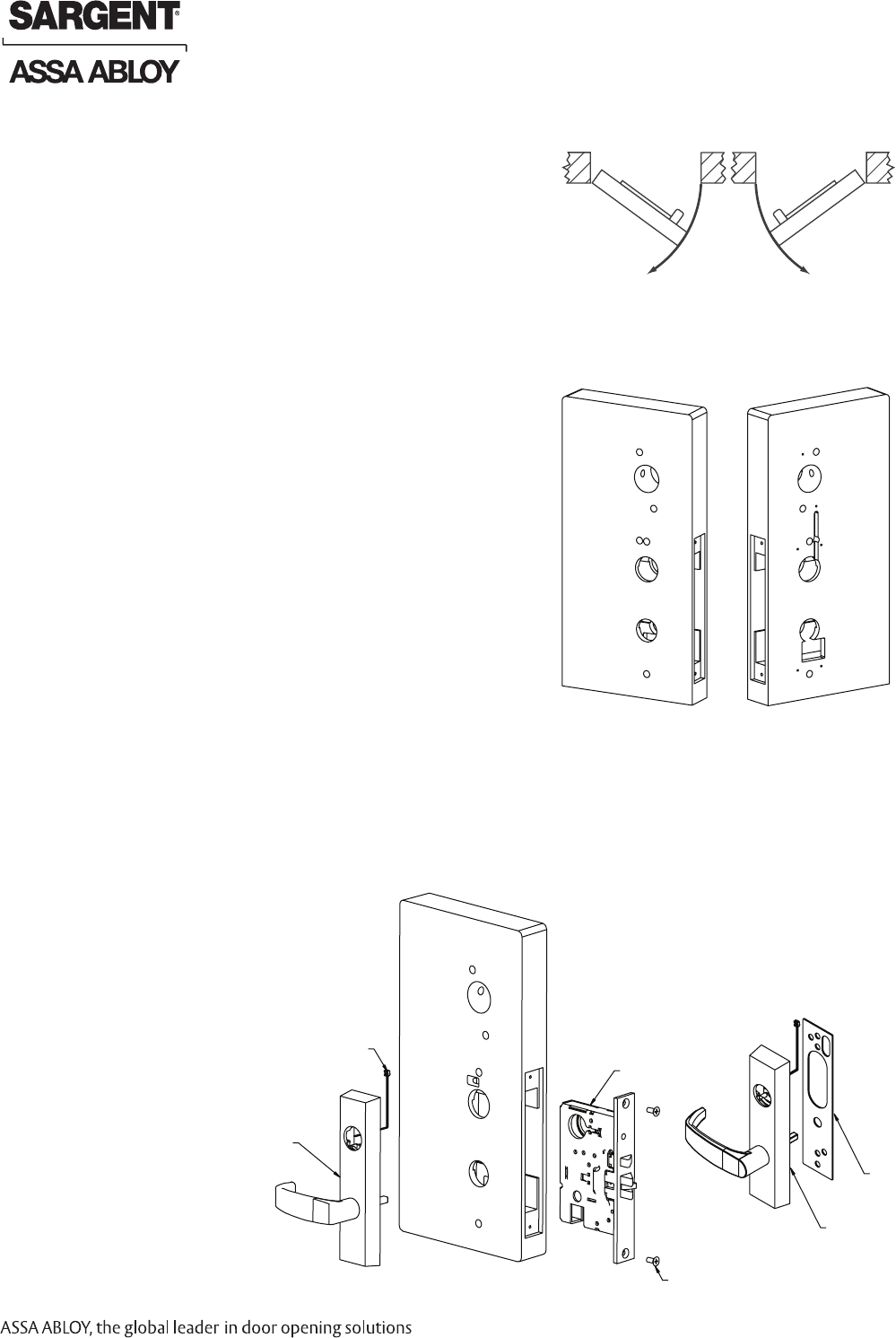
Step #1 – Door Preparation
A. Verify Hand and Bevel of Door
• Check hand of door. Exit Device may be handed.
• Door should be tted and hung.
• Verify box label for size of exit device, function and hand.
B. Door Preparation
Prepare door according to appropriate template. If necessary,
refer to website, www.intelligentopenings.com:
• Field prep template: A7948 (ships with product)
• Door manufacturer templates: 4613, 4290, and 4314.
Note: Instruction examples show wood door installation.
For metal doors, route cables inside door.
Left Hand
Reverse
LHR
Outside
Inside
Right Hand
Reverse
RHR
Fig. 1A
Wood Door Shown
Fig. 1B
Fig. 2B Detail
Fig. 2A
Mortise
Wire
(2) Flat Head Wood Screws
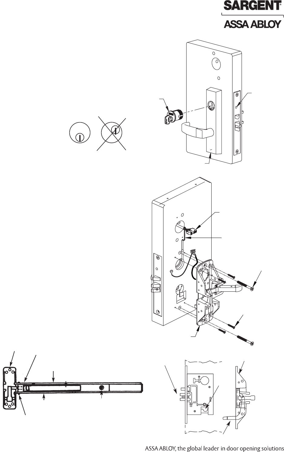
Step #2 – Mortise Lock and Outside Exit Trim (ET) Installation
1. Slide mortise lock into pocket and securely fasten with (2) at head screws (Fig. 2A).
2. Route “ET” harness through wire cutout on inside of door.
3. For exterior applications, use gasket (52-0263)
to seal between ET escutcheon and
outside door surface (Fig. 2B Detail).
4. Place ET control on door with spindle
engaging the mortise lock.
ET
ET
Gasket
Harmony Series H2 8900 Exits
06/30/09 Copyright © 2009 Sargent Manufacturing Company, an ASSA ABLOY Group company. All rights reserved.
Reproductions in whole or in part without express written permission of Sargent Manufacturing Company is prohibited.
A8029A • 800-810-WIRE (9473) • www.sargentlock.com 21
8900 Installation Instructions (Continued)
Step #3 – Cylinder Installation
For devices without cylinders, skip this section.
1. Back cylinder set screw out slightly (Fig. 3A).
2. Insert cylinder through “ET” control and thread into
mortise lock until cylinder is ush with “ET”.
Keyway must be vertical and SARGENT
Position Sargent Logo at top of cylinder (Fig. 3B).
3. Tighten cylinder set screw.
Step #4 – Chassis to Door Installation
1. Route ET wire harness along track cutout for wood doors
and access hole for metal doors (Fig. 4A).
2. Temporarily attach chassis to rail, then lock push rail down
using hex or cylinder key or by holding push rail in the
depressed position on 8900 exit device (Fig. 4B).
3. Position chassis and rail on door so that lever
arm is under rear section of mortise lock lever
then lift up until latch bolt is completely
retracted. With chassis in this position and
rail horizontal, mark location of chassis
mounting holes (Fig. 4C). Drill holes for screws.
4. Release push rail and disassemble chassis
from rail. Mount chassis on door.
Do not pinch harness wires.
5. Fasten exit chassis to door using
(4) #10 wood screws or #10-24 x 3/4”
machine screws.
6. Using (2) 1/4-20 x 2-3/8” at head screws,
attach “ET” to chassis.
Cylinder Set Screw
ET Control
Inside of Door
ElectroLynx Connectors
(4) #10 Wood Screws
or #10-24 Machine Screws
Fig. 3A
Cylinder
Correct Incorrect
SARGENT
SARGENT
Fig. 3B Detail
Wire Harness
(2) 1/4-20 x 2-3/8” Flat
Head Machine Screws
(to secure ET)
Fig. 4B Fig. 4C
Exit Chassis
Fig. 4A
Depress arm into rail opening
and slide rail onto chassis.
Push Rail
Chassis
Rail Assembly
Lock Down Screw
Attach to chassis with (2) #8-32 x 3/8”
Phillips Truss Head Machine Screws
Latchbolt
Lever
Lever Arm
Chassis
Harmony Series H2 8900 Exits
Copyright © 2009 Sargent Manufacturing Company, an ASSA ABLOY Group company. All rights reserved.
Reproductions in whole or in part without express written permission of Sargent Manufacturing Company is prohibited.
06/30/09
A8029A • 800-810-WIRE (9473) • www.sargentlock.com22
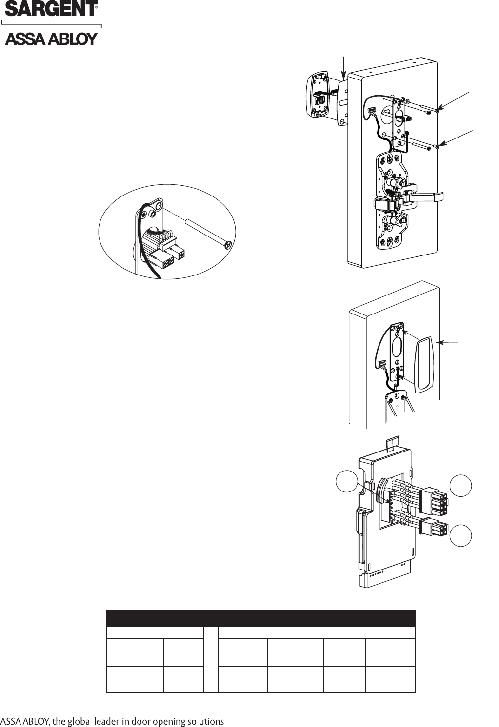
Step #5 – Outside Escutcheon and Inside
Mounting Plate and Ground Wire Installation
1. Connect pin 5 green/yellow ground wire ring terminal to
top right screw (Fig. 5A and 5B).
1. Secure the mounting plate with (2) self-tapping screws (#8 x 1/2”).
2. Feed the reader cable connector located on the back of the outside
escutcheon from the outside of door through door.
3. Securely tighten the outside escutcheon with (2) through-bolts
(#8-32 x 2”) Phillips at head screws through the mounting plate.
Outside Gasket
#8-32 x 2” Phillips
Flat Head Screws
#8 x 1/2” Self-
Taping Screws
Fig. 5A
Inside of Door
Fig. 5B
Step #6 – Install Gasket
Add Gasket (if necessary):
Remember the inside gasket must be used when installing in an
outdoor application.
Remove backing and place gasket on door (Fig. 6A).
Inside of Door
Fig. 6A
PCB Layout - Wire Assignments - ElectroLynx Assembly (Molex)
J2 J1
1-Violet Lock DC Neg
(Solenoid, neg)
3 - Pink
NOT USED
1- Black
PWR GND
3-White
Wiegand DATA 1
5-Orange
RX (N/O)
7-Brown
EGND
2-Gray, Lock DC Pos
(Solenoid, pos)
4-Tan
NOT USED
2-Red
PWR POS
4-Green
Wiegand DATA 0
6-Blue
RX (COM)
8-Yellow
LED
Gasket required
for exterior door
applications.
Harmony Series H2 8900 Exits
Fig. 7A
J1
J2
To ElectroLynx
Harness
J5
From Reader
Board P5 to J5
Step #7 – Connect ElectroLynx
1. Connect P5 (7 Pin Connector) from reader board
to J5 on interior escutcheon PCB assembly (Fig. 7A).
2. Connect ElectroLynx harness (4 and 8-pin) from door harness
to ElectroLynx harness on interior PCB assembly (Fig. 7A).
NOTES:
Neatly fold the wires onto themselves and into the remaining
space to prevent pinching wires when mounting escutcheon.
Do not tuck extra mortise lock body wires back inside the lock
body cylinder hole.
Connectors go on only one way.
Do not offset connector and be sure they are completely seated.
06/30/09 Copyright © 2009 Sargent Manufacturing Company, an ASSA ABLOY Group company. All rights reserved.
Reproductions in whole or in part without express written permission of Sargent Manufacturing Company is prohibited.
A8029A • 800-810-WIRE (9473) • www.sargentlock.com 23
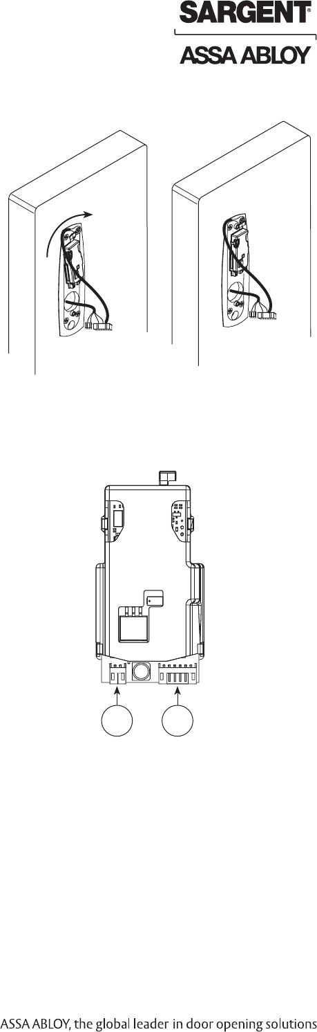
Please follow these steps prior to installing inside escutcheon
assembly to prevent any damage caused by pinching wires:
1. Align the ElectroLynx® connectors (8 and 4-pin) to one side
of the wire guide inside of the door prep. The reader
connections and excess wire are arranged on the other.
2. Connect the ElectroLynx® connectors (8 and 4-pin) and
establish their position inside of the door prep on
the proper side of the wire guide (Fig. 8A).
3. Neatly route the remaining wires onto themselves and into
the remaining space to prevent pinching wires when
mounting the escutcheon (Fig.8B).
Step #8 – Outside Escutcheon and Wire Positioning
Outside of Door
Harmony Series H2 8900 Exits
Fig. 8A Fig. 8B
Rotate Clockwise
From Lock
Body P3 to J3 From Lock
Body P4 to J4
Fig. 9A
J4 J3
Step #9 – Connector Attachment
(Exterior PCB Assembly)
1. Connect P3 (2-pin connector) from lock body
to J3 on module (Fig. 9A).
2. Connect P4 (6-pin connector) from lock body
to J4 on module (Fig. 9A).
Copyright © 2009 Sargent Manufacturing Company, an ASSA ABLOY Group company. All rights reserved.
Reproductions in whole or in part without express written permission of Sargent Manufacturing Company is prohibited.
06/30/09
A8029A • 800-810-WIRE (9473) • www.sargentlock.com24
Fig. 11A
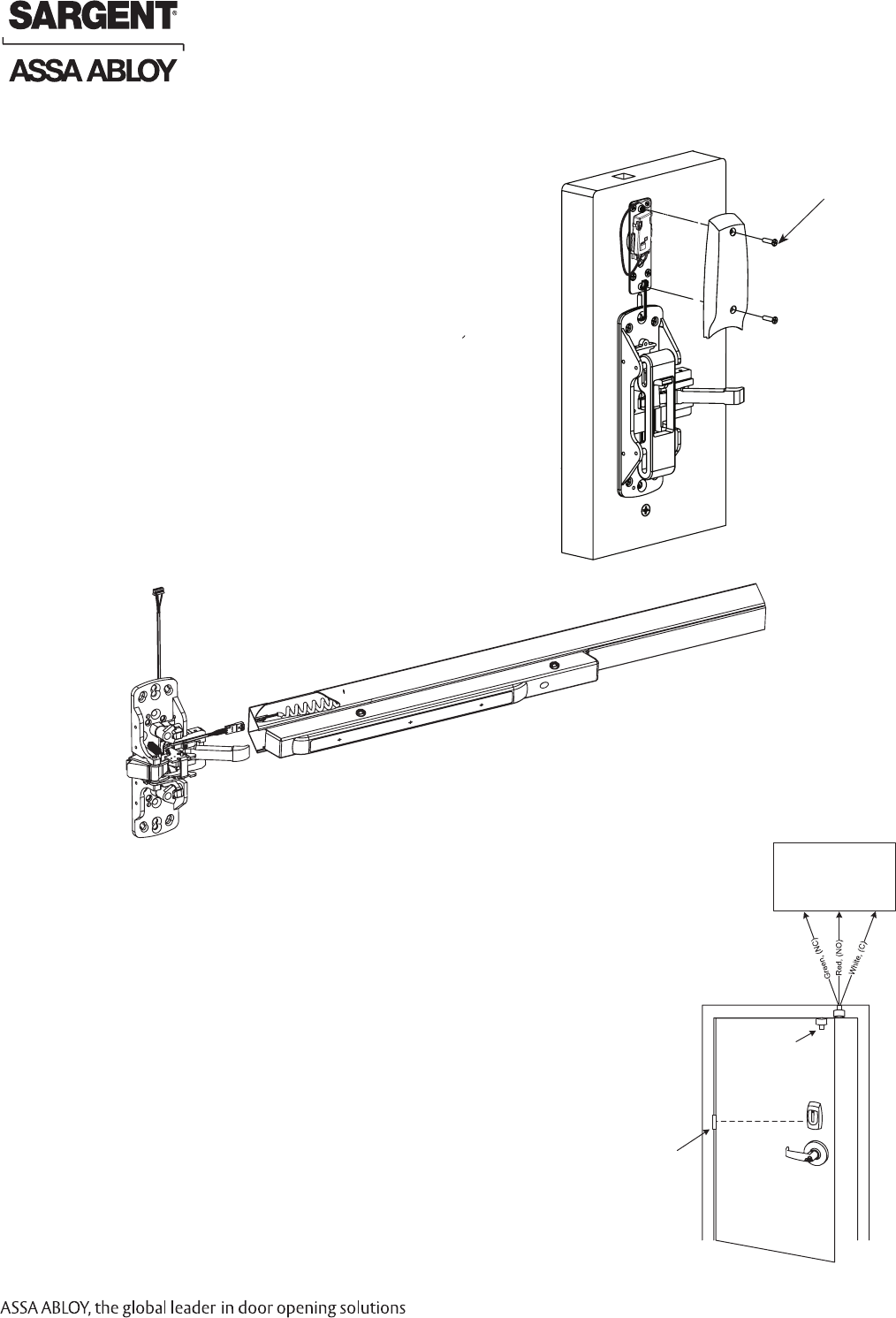
Step #11 – Installation of Rail Assembly
1. Retrieve harness from end of rail. Harness has limited travel
and can be damaged.
2. Attach harness to female connector on chassis.
3. Install rail and screws per exit device instructions.
Note: This view shows rim exit device version
>> Continue to Section 9 for Wiring Diagrams to wire Device to EAC Panel. <<
Step #10 – Installation of Inside Escutcheon
1. Position inside gasket and escutcheon against door. Verify that no
wires are being pinched.
2. Mount inside escutcheon assembly to plate using (2) #8-32 x 5/8"
Phillips at head undercut machine screws.
(2) #8-32 x 5/8” Phillips
Flat Head Under-cut
Machine Screws
Fig. 10A
Inside of Door
Step #12 - Concealed Door Position Switch (3287) Instructions
Use SARGENT 3287 Concealed Door Position Switch with this
Harmony H2 series product:
1. Install the 3287 Concealed Door Position Switch described in SARGENT
document A7448B.
2. Wire the 3287 Concealed Door Position Switch to the EAC door position Input.
3. Connect the common wire of the switch to the common input terminal of the EAC;
and the normally open wire of the switch to the normally open input
termnial of the EAC.
Harmony Series H2 8900 Exits
Fig. 12A
Wiegand Access
Control System
(Others)
McKinney
QC12 Hinge Harmony Series H2
3287 Door
Position Switch
Lock is 12VDC.
Optional 24VDC
lock is available.
06/30/09 Copyright © 2009 Sargent Manufacturing Company, an ASSA ABLOY Group company. All rights reserved.
Reproductions in whole or in part without express written permission of Sargent Manufacturing Company is prohibited.
A8029A • 800-810-WIRE (9473) • www.sargentlock.com 25
Product 8 PIN CONNECTOR 4 PIN CONNECTOR
1-Black 2-Red 3-White 4-Green 5-Orange 6-Blue 7-Brown 8-Yellow 9-Violet 10-Gray 11-Pink 12-Tan
ACCESS CONTROL DEVICES: Harmony H2 Exits, ElectroLynx wire Color / Function assignments
12/24VDC
(Reader)
WIE-
GAND
WIE-
GAND
RX RX EGND LED 12 OR 24 VDC
(LOCK RELAY)
DPS
(NC)
DPS
(COM)
SARGENT -
HARMONY
SERIES,
H2 Exits
NEG POS DATA_1 DATA_0 NO COM EGND REF.
*DIA-
GRAMS
NEG POS N/A N/A
Wiring Diagrams
8
Reader LED Configuration
The Harmony Series reader can be congured for (3) modes of LED operation.
HID Programming cards are supported to congure the behavior for LED
color activity. Call 1-800-WIRE for details.
Mode 1:
• Red LED ‘ON’ when powered.
• Presenting a 13.56MHz credential causes LED to ‘FLICKER’
green and return to red state.
• Reference *Diagram #1 as a function of power
requirement (12VDC or 24VDC).
Note: LED wire is unconnected.
Mode 2:
• Green LED “ON” when powered.
• No Flicker after presenting valid 13.56MHz credential.
• Reference *Diagram #2 as a function of power
requirement (12VDC or 24VDC).
Note: LED wire must be connected to circuit GROUND of the
system’s power supply.
Mode 3:
• EAC Panel controls LED operation.
• Reference *Diagram #3 as a function of power requirement (12VDC or 24VDC).
Note: Control of LED is a function of the EAC panel equipment (ie. relay) to toggle between green and red.
Note: When LED wire is tied directly into EAC panel relay, no AC signals should be applied on wire or door reader
performance will be interfered (*Diagram #3).
*Diagrams on following pages
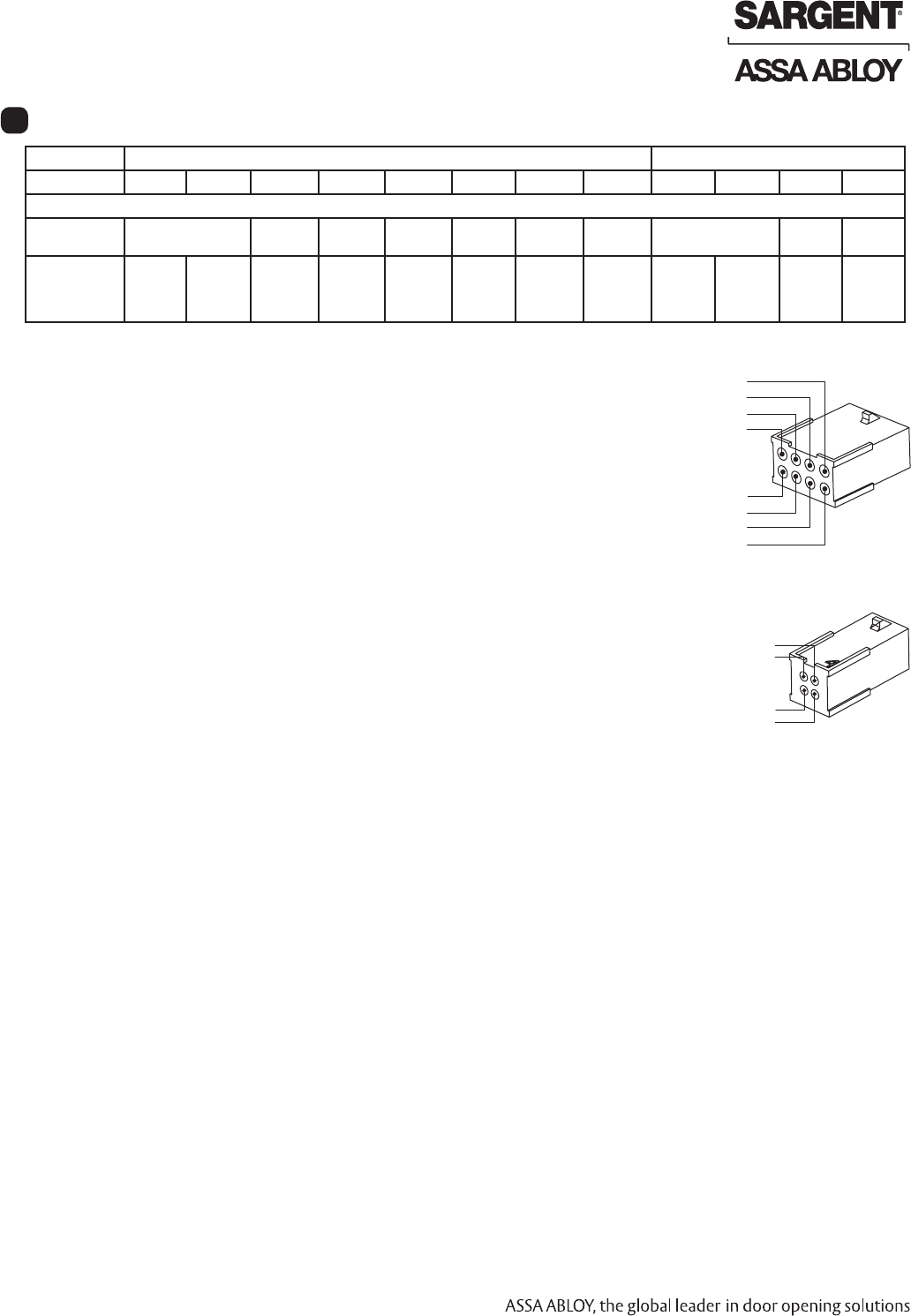
PIN 8 (Yellow – LED)
PIN 6 (Blue – RX COM)
PIN 4 (Green – Data 0)
PIN 2 (Red – Reader POS)
PIN 1 (Black – Reader NEG)
PIN 3 (White – Data 1)
PIN 5 (Orange – RX N/O)
PIN 7 (Brown)
PIN 4 (Not Used)
PIN 2 (Gray – Lock POS)
PIN 1 (Violet – Lock NEG)
PIN 3 (Not Used)
Harmony Series H2 Exit Devices
Copyright © 2009 Sargent Manufacturing Company, an ASSA ABLOY Group company. All rights reserved.
Reproductions in whole or in part without express written permission of Sargent Manufacturing Company is prohibited.
06/30/09
A8029A • 800-810-WIRE (9473) • www.sargentlock.com26
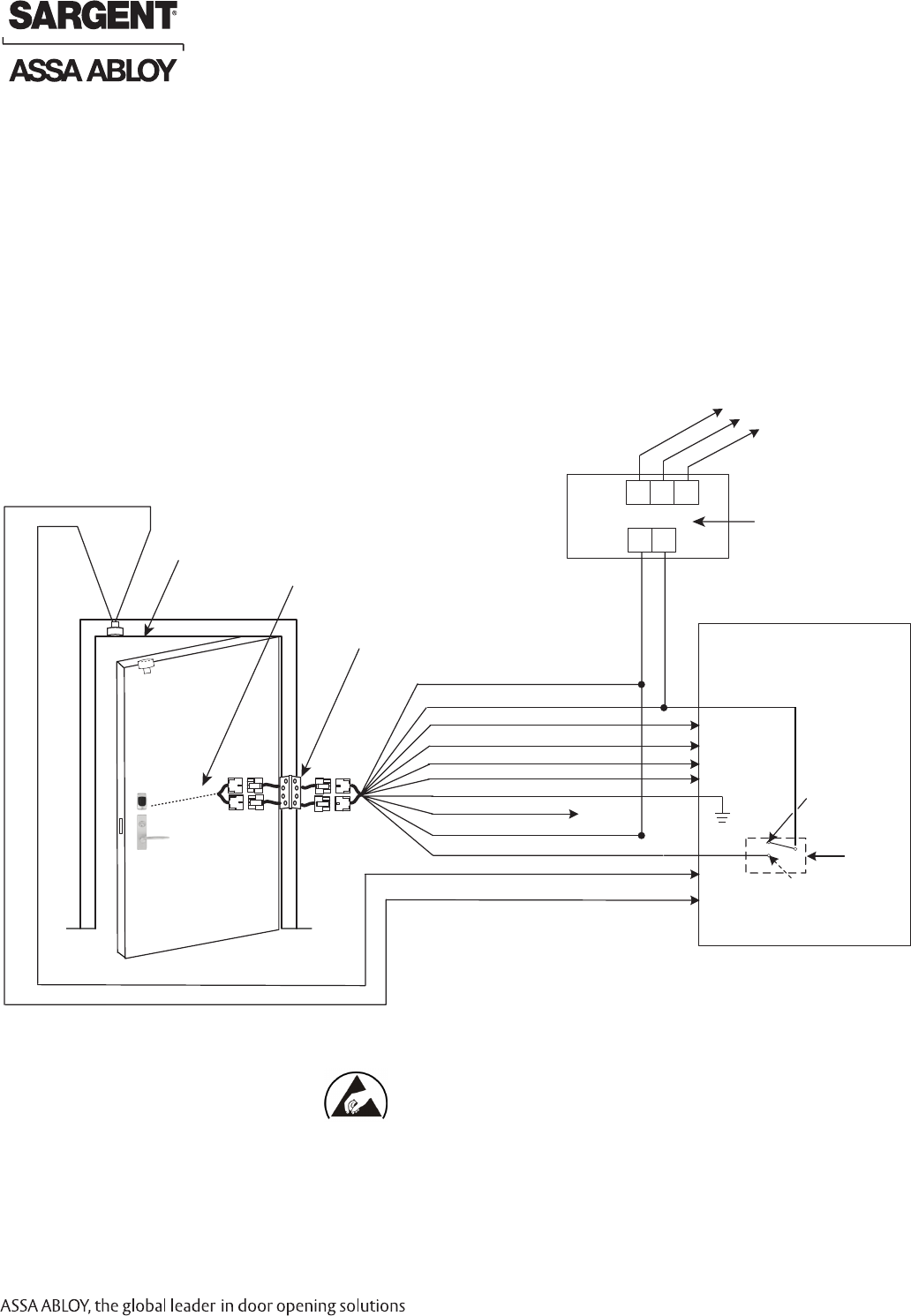
Typical Harmony Exit Application Diagram (12/24VDC Lock)
DIAGRAM #1 – MODE 1: RED LED ‘ON’ WHEN POWERED
12/24VDC SYSTEM
• Reader Draw = 125mA
• 12VDC Solenoid Draw = 500mA
• 12VDC Total Current Draw = 625mA
• 24VDC Solenoid Draw = 250mA
• 24VDC Total Current Draw = 375mA
Power Supply
(By Others)
Electronic Access
Control Panel
(By Others)
Lock Relay
(NO) Fail Secure
Operation
DPS
DPS
DATA 1
DATA 0
RX (NO Option)
RX (COM)
READER NEG - Black, 1
READER POS - Red, 2
DATA 1 - White, 3
DATA 0 - Green, 4
RX (NO) - Orange, 5
RX (COM) - Blue, 6
*EGND - Brown, 7
LED - Yellow, 8
LOCK NEG - Violet, 9
LOCK POS - Gray, 10
Not Used
H2 Harmony Exit
3287 Door
Position Switch
12/24VDC
H N G
- +
120 VAC
Input
Black (Hot)
White (Neutral)
Green (Gnd)
White (C)
Green (NC)
Harmony Series H2
Requires 12 or 24 VDC
Use (NC) for Fail
Safe Operation
Harmony Series H2 Exit Devices
*IMPORTANT: Pin 7 must be tied to earth ground in the access control panel.
Failure to follow proper ESD safe grounding procedures could lead to equipment failure.
QC12 Electric Hinge
From McKinney
12 Conductor
ElectroLynx Harness
From McKinney
06/30/09 Copyright © 2009 Sargent Manufacturing Company, an ASSA ABLOY Group company. All rights reserved.
Reproductions in whole or in part without express written permission of Sargent Manufacturing Company is prohibited.
A8029A • 800-810-WIRE (9473) • www.sargentlock.com 27
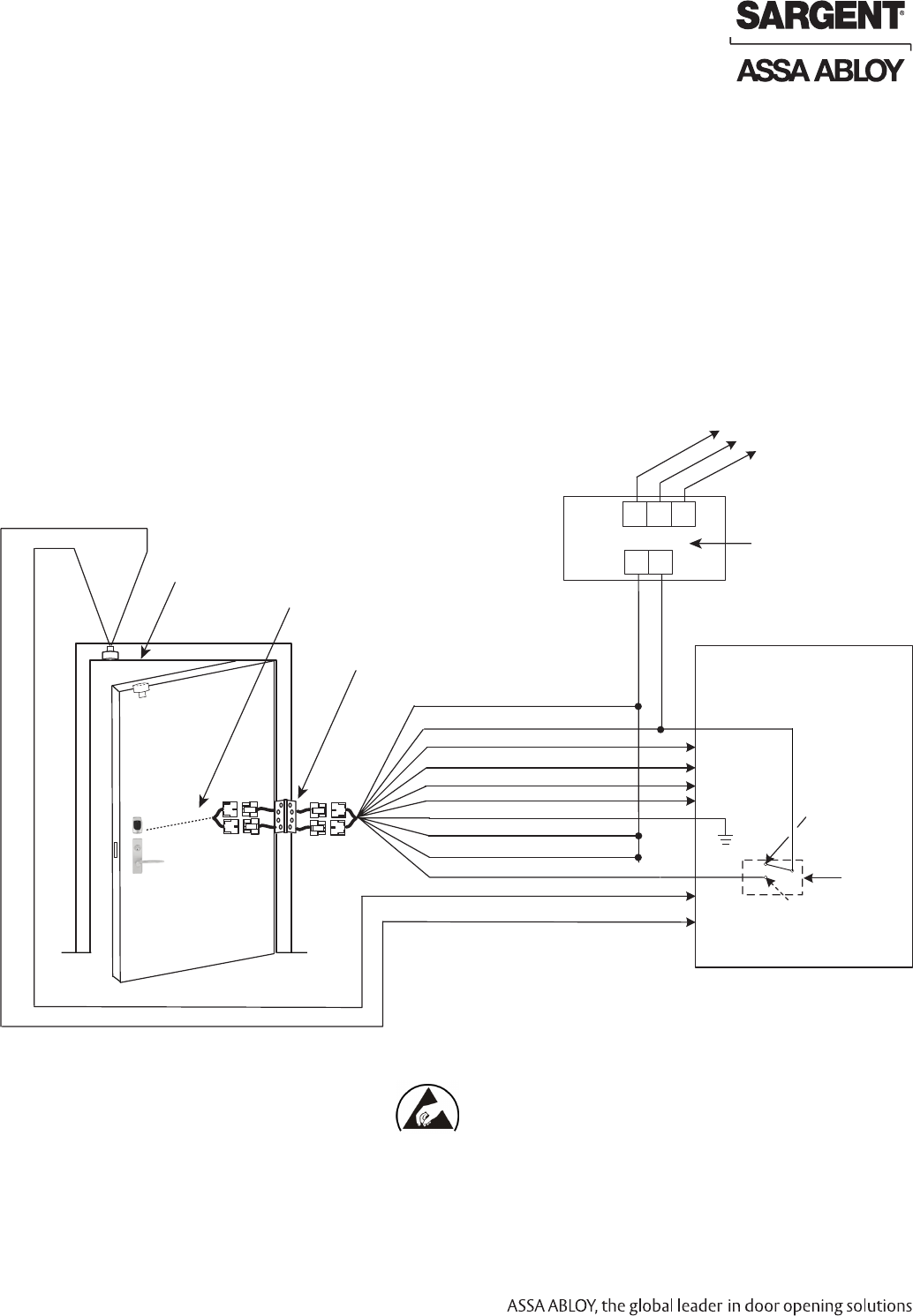
Typical Harmony Exit Application Diagram (12/24VDC Lock)
DIAGRAM #2 – MODE 2: GREEN LED ‘ON’ WHEN POWERED
Power Supply
(By Others)
Electronic Access
Control Panel
(By Others)
Lock Relay
(NO) Fail Secure
Operation
DPS
DPS
DATA 1
DATA 0
RX (NO Option)
RX (COM)
READER NEG - Black, 1
READER POS - Red, 2
DATA 1 - White, 3
DATA 0 - Green, 4
RX (NO) - Orange, 5
RX (COM) - Blue, 6
*EGND - Brown, 7
LED - Yellow, 8
LOCK NEG - Violet, 9
LOCK POS - Gray, 10
DPS (NC) - Pink, 11
DPS (COM) - Tan, 12
3287 Door
Position Switch
12/24VDC
H N G
- +
120 VAC
Input
Black (Hot)
White (Neutral)
Green (Gnd)
White (C)
Green (NC)
Use (NC) for Fail
Safe Operation
12/24VDC SYSTEM
• Reader Draw = 125mA
• 12VDC Solenoid Draw = 500mA
• 12VDC Total Current Draw = 625mA
• 24VDC Solenoid Draw = 250mA
• 24VDC Total Current Draw = 375mA
Harmony Series H2
Requires 12 or 24 VDC
H2 Harmony Exit
Harmony Series H2 Exit Devices
*IMPORTANT: Pin 7 must be tied to earth ground in the access control panel.
Failure to follow proper ESD safe grounding procedures could lead to equipment failure.
12 Conductor
ElectroLynx Harness
From McKinney
QC12 Electric Hinge
From McKinney
Copyright © 2009 Sargent Manufacturing Company, an ASSA ABLOY Group company. All rights reserved.
Reproductions in whole or in part without express written permission of Sargent Manufacturing Company is prohibited.
06/30/09
A8029A • 800-810-WIRE (9473) • www.sargentlock.com28
Harmony Series H2 Exit Devices
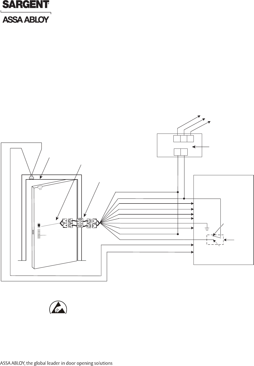
Typical Harmony Exit Application Diagram (12/24VDC Lock)
DIAGRAM #3 – MODE 3: EAC PANEL CONFIGURABLE
Power Supply
(By Others)
Electronic Access
Control Panel
(By Others)
Use (NC) for Fail
Safe Operation
Lock Relay
(NO) Fail Secure
Operation
DPS
DPS
DATA 1
DATA 0
RX (NO Option)
RX (COM)
LED
READER NEG - Black, 1
READER POS - Red, 2
DATA 1 - White, 3
DATA 0 - Green, 4
RX (NO) - Orange, 5
RX (COM) - Blue, 6
*EGND - Brown, 7
LED - Yellow, 8
LOCK NEG - Violet, 9
LOCK POS - Gray, 10
H2 Harmony Exit
3287 Door
Position Switch
12/24DC
H N G
- +
120 VAC
Input
Black (Hot)
White (Neutral)
Green (Gnd)
White (C)
Green (NC)
12/24VDC SYSTEM
• Reader Draw = 125mA
• 12VDC Solenoid Draw = 500mA
• 12VDC Total Current Draw = 625mA
• 24VDC Solenoid Draw = 250mA
• 24VDC Total Current Draw = 375mA
Harmony Series H2
Requires 12 or 24 VDC
*IMPORTANT: Pin 7 must be tied to earth ground in the access control panel.
Failure to follow proper ESD safe grounding procedures could lead to equipment failure.
12 Conductor
ElectroLynx Harness
From McKinney
QC12 Electric Hinge
From McKinney
A8029A-06/30/09
SARGENT
100 Sargent Drive
New Haven, CT 06511 USA
800-481-8464 • www.sargentlock.com
Founded in the early 1800s, SARGENT® is a market leader in locksets, cylinders, door closers, exit devices,
electro-mechanical products and access control systems for new construction, renovation, and replacement applications.
The company’s customer base includes commercial construction, institutional, and industrial markets.
Copyright © 2009, Sargent Manufacturing Company, an ASSA ABLOY Group company. All rights reserved.
Reproduction in whole or in part without the express written permission of Sargent Manufacturing Company is prohibited.
ASSA ABLOY is the global leader in door opening solutions, dedicated to
satisfying end-user needs for security, safety and convenience.
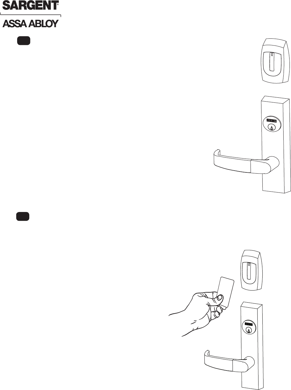
For devices without cylinders, go to step 3.
1. For devices with cylinders, insert key into cylinder and rotate.
2. The key will retract the latch and rods, the key should rotate freely.
3. Depress inside rail to retract latch and rods.
Mechanical Operational Check
Note: Once electrical wiring has been successfully
completed according to proper application, follow the
following step:
1. Turn power ON.
2. Verify LED located on reader is ON - red or green,
depending on reader conguration (see reader
LED conguration).
3. Present credential and verify LED and
sounder activity.
4. Verify valid card read at EAC Panel.
5. Verify system operation functions; i.e., when
credential is presented to reader that the
door unlocks.
Electrical Operational Check
11
.
10