ASSALOY SCYPROX5 Microprocessor Controlled Network Lock User Manual 12 0305 Exhibit Cover
ASSA ABLOY Inc. Microprocessor Controlled Network Lock 12 0305 Exhibit Cover
ASSALOY >
Manual

5015 B.U. Bowman Drive Buford, GA 30518 USA Voice: 770-831-8048 Fax: 770-831-8598
Certification Exhibit
FCC ID: U4A-SCYPROX5
IC: 6982A-SCYPROX5
FCC Rule Part: 15.209, 15.249
IC Radio Standards Specification: RSS-210
ACS Project Number: 12-0305
Manufacturer: Assa Abloy
Model: C2-PA/PK
Manual
A8122B
8/12
Copyright 2012, Sargent Manufacturing Company, an ASSA ABLOY Group company.
All rights reserved. Reproduction in whole or in part without the express written
permission of Sargent Manufacturing Company is prohibited.
These installation instructions include Microsoft® Tags that you can
scan to view videos of certain installation steps. The Microsoft Tag
mobile app is required to scan the Tags. Download the free mobile
app at http://gettag.mobi
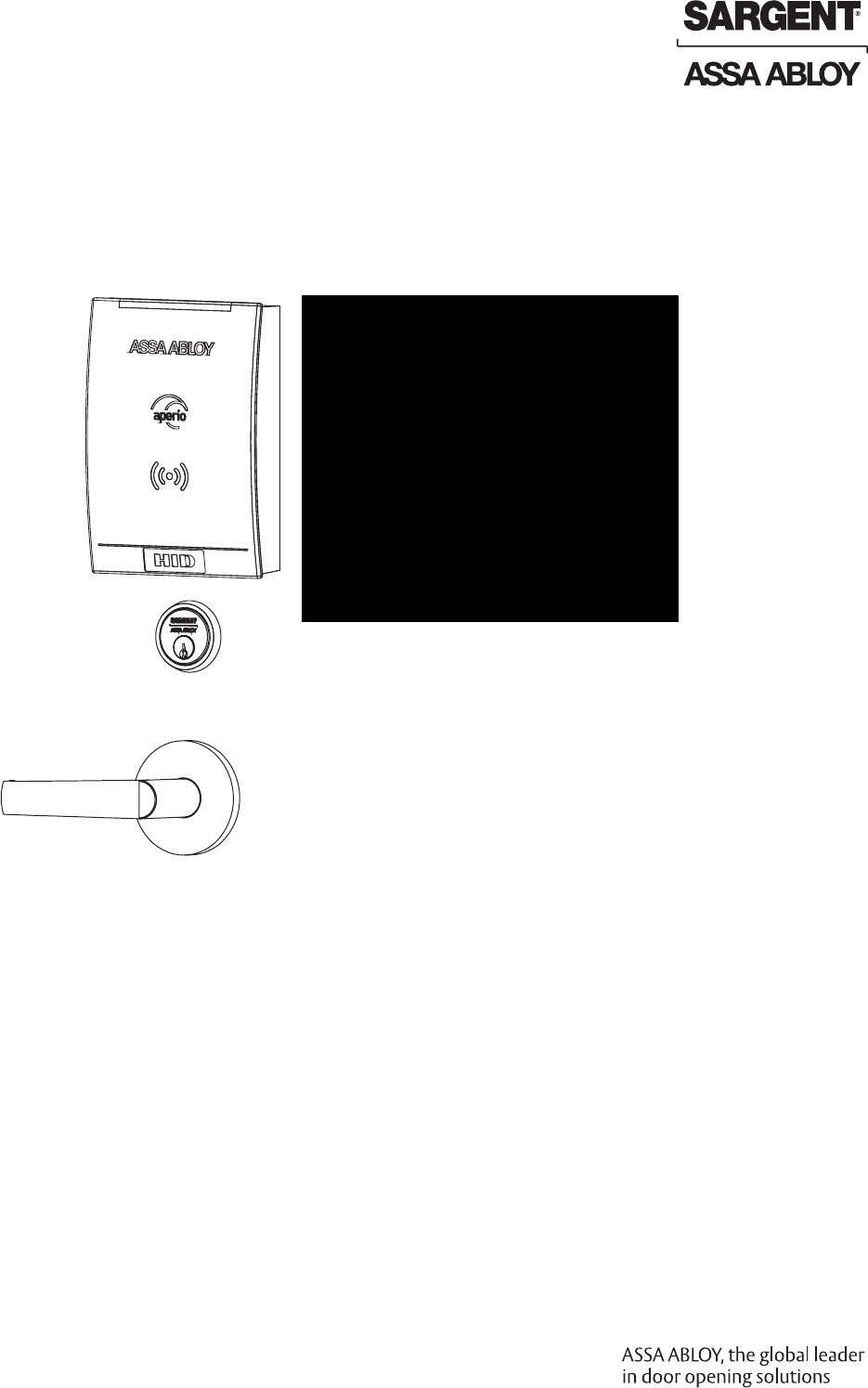
with Aperio™
Technology
Mortise Lock
Installation Instructions
IN100
Preliminary
1-800-810-WIRE • www.sargentlock.com • A8122B
Copyright © 2012, Sargent Manufacturing Company, an ASSA ABLOY Group company. All rights reserved.
Reproductions in whole or in part without express written permission of Sargent Manufacturing Company is prohibited.
8/05/12
1
2
3
4
5
6
7
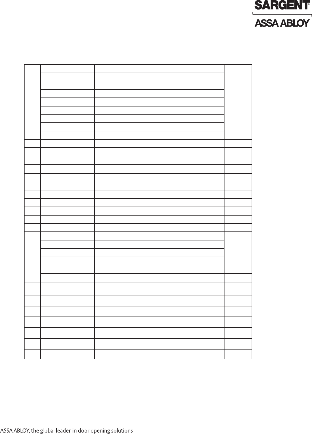
Table of Contents
Warning ...................................................................................2
General Description .................................................................3
Specifications ..........................................................................3
System Overview .....................................................................3
Parts Breakdown .....................................................................4
Lock Installation ......................................................................6
Maintenance .........................................................................15
Operational Check ................................................................16
Lock LED Indications ............................................................17
Changes or modifications to this device not expressly approved by ASSA ABLOY
could void the user’s authority to operate the equipment.
Warning
1
FCC:
This equipment has been tested and found to comply with the limits for a Class B digital device, pursuant to Part
15 of the FCC Rules. These limits are designed to provide reasonable protection against harmful interference in a
residential installation. This equipment generates, uses, and can radiate radio frequency energy and, if not installed
and used in accordance with the instructions, may cause harmful interference to radio communications. However,
there is no guarantee that interference will not occur in a particular installation. If this equipment does cause harmful
interference to radio or television reception, which can be determined by turning the equipment off and on, the user
is encouraged to try to correct the interference by one or more of the following measures:
• Reorient or relocate the receiving antenna.
• Increase the separation between the equipment and receiver.
• Connect the equipment into an outlet on a circuit different from that to which the receiver is connected.
• Consult the dealer or an experienced radio/TV technician for help.
Industry Canada:
This Class B digital apparatus meets all requirements of the Canadian Interference Causing Equipment Regulations.
Operation is subject to the following two conditions: (1) this device may not cause harmful interference, and (2) this
device must accept any interference received, including interference that may cause undesired operation.
Cet appareillage numérique de la classe B répond à toutes les exigences de l’interférence canadienne causant des
règlements d’équipement. L’opération est sujette aux deux conditions suivantes: (1) ce dispositif peut ne pas causer
l’interférence nocive, et (2) ce dispositif doit accepter n’importe quelle interférence reçue, y compris l’interférence qui
peut causer l’opération peu désirée.
“This equipment complies with FCC radiation exposure limits set forth for an uncontrolled environment. This
equipment should be installed and operated with minimum distance 20cm between the radiator and your body. This
transmitter must not be co-located or operating in conjunction with any other antenna or transmitter.”
Under Industry Canada regulations, this radio transmitter may only operate using an antenna of a type and maximum
(or lesser) gain approved for the transmitter by Industry Canada. To reduce potential radio interference to other
users, the antenna type and its gain should be so chosen that the equivalent isotropically radiated power (e.i.r.p.) is
not more than that necessary for successful communication.
Conformément à la réglementation d’Industrie Canada, le présent émetteur radio peut fonctionner avec une antenne
d’un type et d’un gain maximal (ou inférieur) approuvé pour l’émetteur par Industrie Canada. Dans le but de réduire
les risques de brouillage radioélectrique à l’intention des autres utilisateurs, il faut choisir le type d’antenne et son
gain de sorte que la
puissance isotrope rayonnée équivalente (p.i.r.e.) ne dépasse pas l’intensité nécessaire à l’établissement d’une
communication satisfaisante.
Any retrofit or other field modification to a fire rated opening can potentially impact the fire rating of the opening,
and SARGENT Manufacturing makes no representations or warranties concerning what such impact may be in
any specific situation. When retrofitting any portion of an existing fire rated opening, or specifying and installing a
new fire-rated opening, please consult with a code specialist or local code official (Authority Having Jurisdiction) to
ensure compliance with all applicable codes and ratings.
8
9
!
Preliminary
8/05/12
1-800-810-WIRE • www.sargentlock.com • A8122B 3
Copyright © 2012, Sargent Manufacturing Company, an ASSA ABLOY Group company. All rights reserved.
Reproductions in whole or in part without express written permission of Sargent Manufacturing Company is prohibited.
IN100 Mortise Lock
Warning: SARGENT Mfg. Co. IN100 locksets utilizing a door position switch (DPS) are not rated for, or intended
for use in life safety applications.
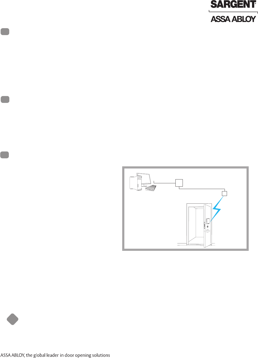
System Overview
4
!To comply with “Fire Listed” doors, the batteries must be replaced with alkaline batteries only.
Specifications
General Description
2
3
The SARGENT® IN100 mortise lock with Aperio™ Technology makes it easy and cost-effective to bring ac-
cess control to doors. It uses local wireless communication between the lock and an Aperio hub to connect
to an access control system, eliminating the greatest cost and inconvenience of traditional access control
– the wiring at the door. The IN100 utilizes HID® iCLASS® 13.56 MHz smart card technology and all technol-
ogy features are supported by the physical security of SARGENT ANSI/BHMA Grade 1 hardware.
This product is operated by six (6) “AA” alkaline batteries. SARGENT mortise locks are designed with quality
components to provide high security, performance, and durability.
The IN100 mortise lock may be used for both indoor and exterior applications. A weather-protective
gasket is required for exterior applications.
Lock
• IEEE 802.15.4 UHF interface
• AES 128 bit encryption
Credential Support
• HID 13.56 MHz iCLASS (full authentication, all formats
• HID 125 kHz prox
When a user presents a supported credential to
the lock, the Aperio system is designed to send
the credential wirelessly to the Aperio Hub. The
Aperio Hub (wired through RS-485 or Wiegand)
then communicates with an EAC (Electronic
Access Control) system. The EAC system provides
the access decision to the Aperio Hub where
access to the lock is either granted or denied.
Access Control Panel
Aperio Hub
Electronic Access
Control System
TCP/IP
RS-485/Wiegand
IEEE 802.15.4
(2.4GHz)
IN100 Patent
Pending
Preliminary
4 1-800-810-WIRE • www.sargentlock.com • A8122B
Copyright © 2012, Sargent Manufacturing Company, an ASSA ABLOY Group company. All rights reserved.
Reproductions in whole or in part without express written permission of Sargent Manufacturing Company is prohibited.
8/050/12
IN100 Mortise Lock
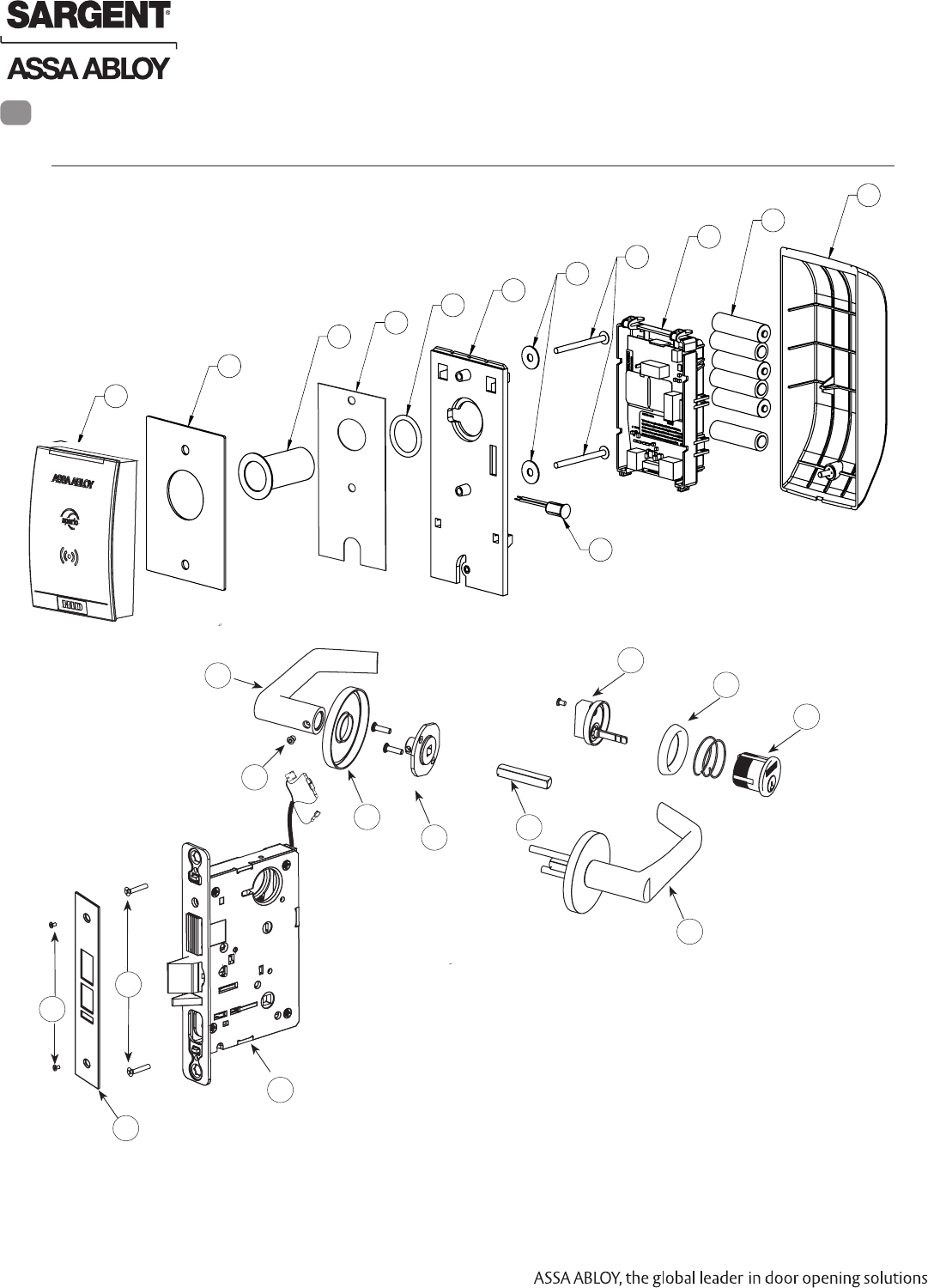
Parts Breakdown
13.56 MHz iCLASS & 125kHz Prox
5
4
1*
2
3
5
6
1*
7
8
6
10
3
13
14
15
15
16
18
17
19
21 21
20
19
Tools Required:
• #2 Phillips screwdriver
• Flat head
• T20 Torx Driver
• Security allen wrench
(provided)
21
* Patent pending
Preliminary
8/05/12
1-800-810-WIRE • www.sargentlock.com • A8122B 5
Copyright © 2012, Sargent Manufacturing Company, an ASSA ABLOY Group company. All rights reserved.
Reproductions in whole or in part without express written permission of Sargent Manufacturing Company is prohibited.
IN100 Mortise Lock
1 52-4481 Reader Assembly* 1
52-5359 Incepta Electronic Replacement Pack, iCLASS only, IA-C2, 7976
52-5360 Incepta Electronic Replacement Pack, iCLASS only, IA-C2 , 7977
52-5361 Incepta Electronic Replacement Pack, iCLASS only, IA-C2 , 7978
52-5362 Incepta Electronic Replacement Pack, iCLASS only, IA-C2 , 7979
52-5363 Incepta Electronic Replacement Pack, Prox only, PA-C2 , 7976
52-5364 Incepta Electronic Replacement Pack, Prox only, PA-C2 , 7977
52-5365 Incepta Electronic Replacement Pack, Prox only, PA-C2 , 7978
52-5366 Incepta Electronic Replacement Pack, Prox only, PA-C2 , 7979
2 52-1332 Gasket (Optional) 1
3 52-2847 Conduit Pack (Optional) 1
4 52-1370 Fire Shield* 1
5 52-1327 Mounting Plate 1
6 52-4488 Screw Pack 1
7 01-0898 AA battery 6
8 52-4483 Inside Cover Assembly 1
9 52-4321 Door Position Switch Pack 1
10 A8120 Field Prep Template (not shown) 1
11 4697 Door Manufacturers Template (not shown) 1
12 A8122 Instructions (not shown) 1
13 C2-7976-hand-finish Lock body with dead bolt with Cylinder 1
C2-7977-hand-finish Lock body with dead bolt without Cylinder
C2-7978-hand-finish Lock body without dead bolt with Cylinder
C2-7979-hand-finish Lock body without dead bolt without Cylinder
14 79-0035 Without dead bolt 1
79-0036 With dead bolt (shown) 1
15 77-4236 Mortise Screw Pack - Specify Finish (Includes: Wood and Metal
Lock body Screws, Faceplate Screws, and Strike Screws)
1
16 Consult Factory #41 Mortise Cylinder 1
17 13-2131 97 Ring 1
18 77-4081 130W Turn Lever 1
19 Consult Factory Reference Incepta Catalog 2
20 78-3696 O-rose 2
21 79-2162 Trim Pack 1
ITEM PART NO. DESCRIPTION QTY.
Parts Breakdown 13.56 MHz iCLASS & 125kHz Prox (Continued)
* Patent Pending
Preliminary
6 1-800-810-WIRE • www.sargentlock.com • A8122B
Copyright © 2012, Sargent Manufacturing Company, an ASSA ABLOY Group company. All rights reserved.
Reproductions in whole or in part without express written permission of Sargent Manufacturing Company is prohibited.
8/050/12
IN100 Mortise Lock
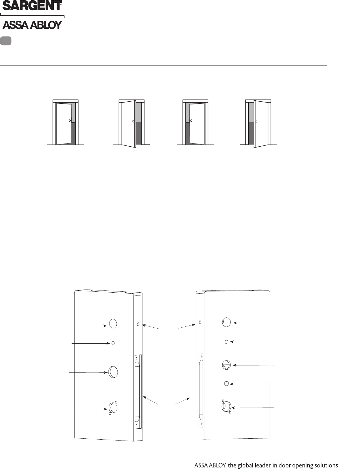
A. Verify Hand and Bevel of Door
Stand on outside of locked door when determining door hand.
Lock Installation
LH
Left Hand
Hinges Left
Open Inward
LHRB
Left Hand
Reverse Bevel
Hinges Left
Open Outward
RH
Right Hand
Hinges Right
Open Inward
RHRB
Right Hand
Reverse Bevel
Hinges Right
Open Outward
Fig. 1A
1 Prepare Door
6
B. Door Preparation
Prior to installation, all holes must be free of burrs, debris and sharp edges.
Prepare door according to appropriate template (see website www.intelligentopenings.com).
• Field Template: A8120 (ships with product)
• Door Manufacture’s Template: 4697
Through-bolt Hole
Thumb Turn Lever Hole Outside Cylinder Hole
(only with cylinder
installation)
Outside of Door
Inside of Door
Ribbon Cable Hole
Lever Handle Hole
Through-bolt Hole
Ribbon Cable Hole
Inside of Lock body
Wire Hole
Lever Handle Hole
Through-bolt Hole
Mortised
Pocket
Thumb Turn Lever Hole
Fig. 1B
External DPS
Hole
Preliminary
8/05/12
1-800-810-WIRE • www.sargentlock.com • A8122B 7
Copyright © 2012, Sargent Manufacturing Company, an ASSA ABLOY Group company. All rights reserved.
Reproductions in whole or in part without express written permission of Sargent Manufacturing Company is prohibited.
IN100 Mortise Lock
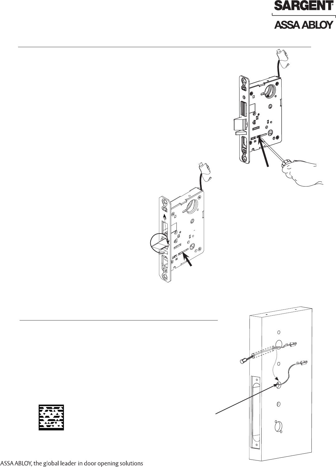
2 How to Change Hand of Lock body
1. Position lock body so the red surface of the locking piece is visible.
2. Insert blade type screwdriver into locking piece slot to rotate
locking piece.
3. Push locking piece toward the back of the lock
body and rotate the locking piece 180°.
Note: Red indicates locked (outside) side.
Fig. 2A
A. Reverse Lock Hand
1. Rotate the latchbolt 180°.
2. Flip deadlatch by hand to match bevel of latchbolt.
B. Reverse Latch Hand
Locking piece
Fig. 2B
Locking piece
Outside of Door
3 Install Door Position Switch (DPS)
1. Insert DPS into the raceway on the latch edge of the door.
2. Push wires through raceway toward lock prep.
For hollow metal doors with a conduit installed, route DPS wire to
the same preparation hole as the cylinder hole.
3. Push DPS firmly into place by hand.
Note: DO NOT TAP SWITCH WITH ANY TOOL.
4. Install magnet into door frame. Push firmly into place by hand.
See A7983A.
5. To connect DPS to lock controller per diagram, refer to the wiring in
Step #14 section 3.
Fig. 3
Note: Alternate routing for
hollow metal doors when
using optional weather
conduit, p/n 52-2847.
Door Position
Switch (DPS)
Scan this Microsoft® Tag using your mobile phone
to see a video of this installation step. The Microsoft
Tag mobile app is required to scan the Tag.
Download the free mobile app at http://gettag.mobi
Preliminary
8 1-800-810-WIRE • www.sargentlock.com • A8122B
Copyright © 2012, Sargent Manufacturing Company, an ASSA ABLOY Group company. All rights reserved.
Reproductions in whole or in part without express written permission of Sargent Manufacturing Company is prohibited.
8/050/12
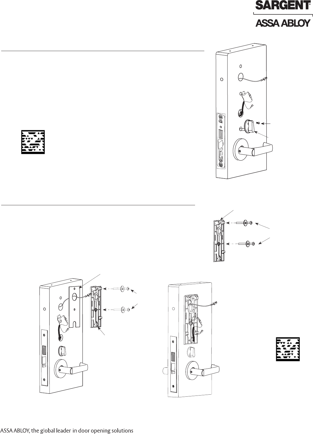
IN100 Mortise Lock
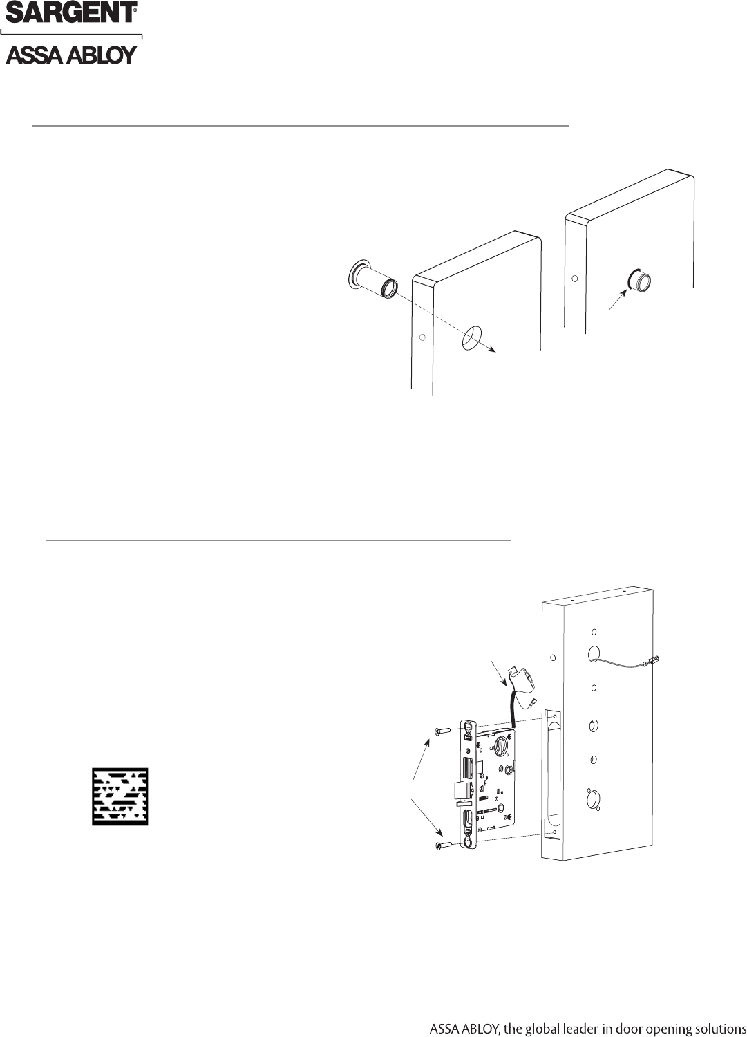
4
Weather Conduit Installation (Optional P/N 52-2847)
Fig. 4A
Install weather conduit on NON FIRE-RATED metal exterior doors only (Fig. 4A).
1. Carefully insert the weather conduit into the ribbon cable hole
from the outside of the door.
2. Place the O-ring around the weather conduit on the inside and
up against the door (Fig. 4B).
Fig. 4B
O-Ring
Inside of Door
5 Install Lock body
1. Feed the wire harness through the mortise pocket
and inside preparation hole as depicted in Fig. 5.
2. Carefully push the lock body into the pocket while lightly
applying tension to the wire harness.
Note: Do not pull the lock into the pocket with the
harness alone. Ensure that the wire harness is not
pinched between the lock and the mortise pocket.
3. Insert (2) #12-24 screws into the lock body
and tighten with a screw driver.
Mortise
Connectors
Fig. 5
Inside of Door
(2) #12-24 screws
Scan this Microsoft® Tag using your mobile phone to
see a video of this installation step. The Microsoft Tag
mobile app is required to scan the Tag. Download the
free mobile app at http://gettag.mobi
Preliminary
8/05/12
1-800-810-WIRE • www.sargentlock.com • A8122B 9
Copyright © 2012, Sargent Manufacturing Company, an ASSA ABLOY Group company. All rights reserved.
Reproductions in whole or in part without express written permission of Sargent Manufacturing Company is prohibited.
IN100 Mortise Lock
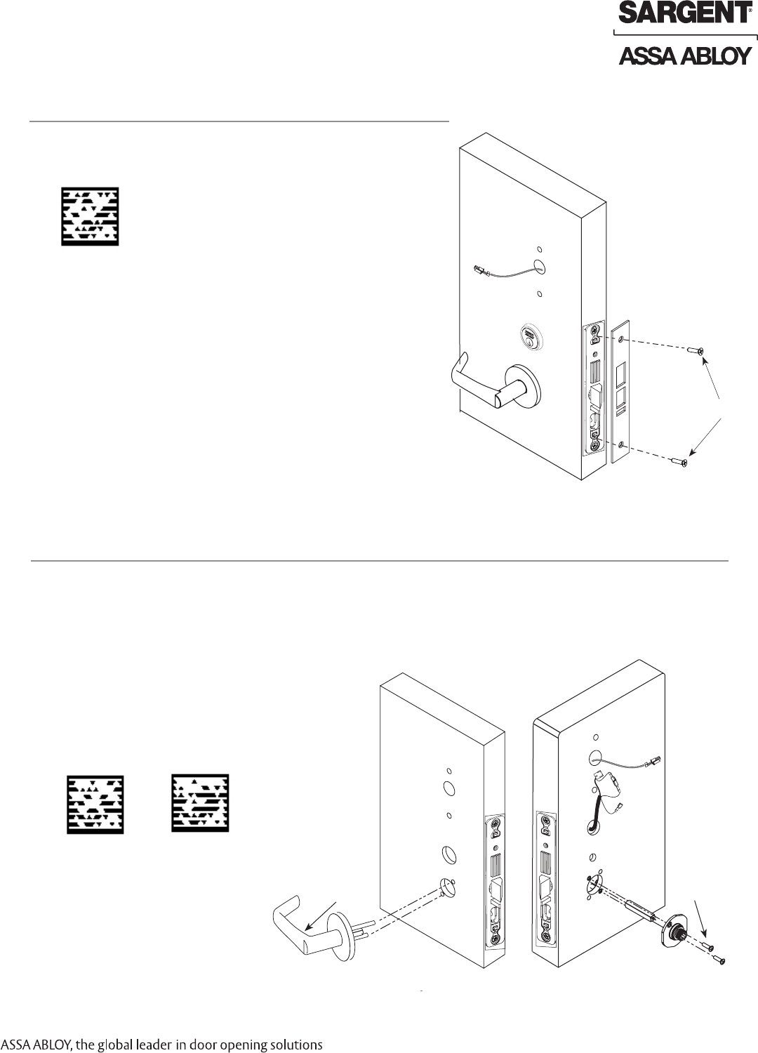
6
Attach Front Plate
Attach front plate with (2) flat head screws. Outside of Door
Fig. 6
(2) flat head screws
Scan this Microsoft® Tag using your mobile phone
to see a video of this installation step. The Microsoft
Tag mobile app is required to scan the Tag.
Download the free mobile app at http://gettag.mobi
7 Assemble Trim
1. With outside lever horizontal, insert the mounting post through outside of door and lock body.
Make certain the lever spindle is properly engaged inside the lock body (Fig 7A).
2. On the inside of the door, insert spindle into square hole of mortise lock (Fig 7B).
3. Slide inside adapter and plate assembly over spindle and secure with (2) 8-32 X 5/8” Phillips
oval head and lock washer machine screws.
Fig. 7B
Fig. 7A
8-32 X 5/8”
Phillips
Oval
Head and
Lock
Washer
Machine
Screw
Inside of DoorOutside of Door
Outside Trim
Scan this Microsoft® Tag using your
mobile phone to see a video of this
installation step. The Microsoft Tag
mobile app is required to scan the
Tag. Download the free mobile app at
http://gettag.mobi
Assemble Trim Inside Lever
Assembly
Preliminary
10 1-800-810-WIRE • www.sargentlock.com • A8122B
Copyright © 2012, Sargent Manufacturing Company, an ASSA ABLOY Group company. All rights reserved.
Reproductions in whole or in part without express written permission of Sargent Manufacturing Company is prohibited.
8/050/12
IN100 Mortise Lock
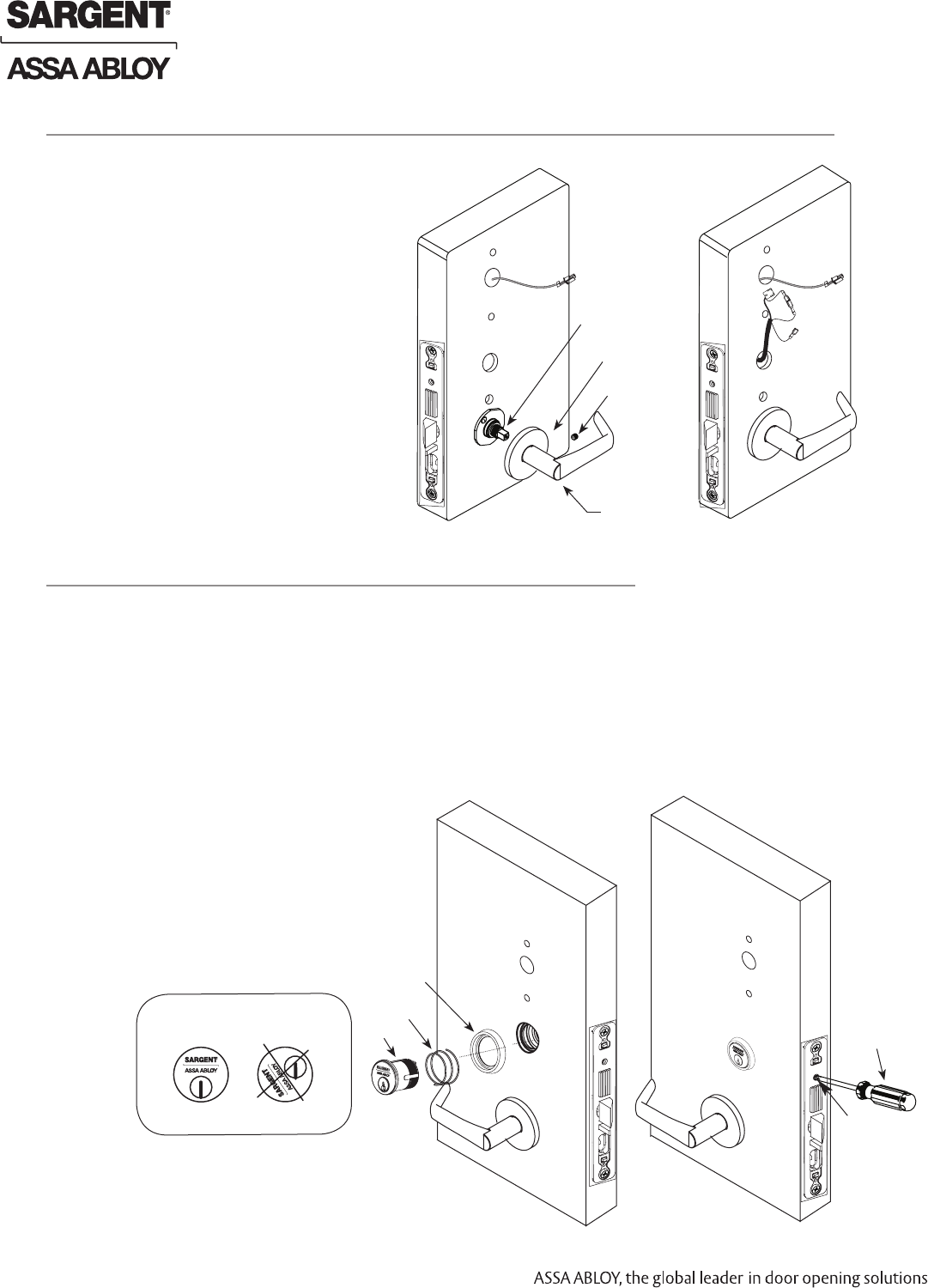
Fig. 8A Fig. 8B
Set Screw
Inside Lever
Spindle
Rose
1. Rotate the inside rose first counter clock
wise to seat the threads then clockwise
to securely tighten.
2. Slide lever handle onto spindle until fully
seated. Be sure handle is horizontal and
facing the hinge side of the door. Push
lever onto spindle so minimum gap
is visible.
3. Tighten the set screw securely with
a T20 Torx.
4. Before closing the door, test that the
lever is functional and ensure
smooth operation of the
latchbolt.
8
Install Inside Rose and Inside Lever Assembly
Inside of Door
Fig. 9B
1. Slide the spring and the rosette onto the cylinder.
2. Rotate the cylinder into cylinder hole with fingers.
3. Insert key 75% of the way and utilize the key to rotate the cylinder into the rest of the cylinder hole.
Note: Do not attempt to tighten all the way.
4. Verify the orientation of the cylinder has the Sargent logo as depicted in Fig. 9A.
5. Hand tighten the cylinder clamp screw with Phillips screwdriver
to prevent unscrewing of the cylinder (Fig 9C).
6. Test cylinder function:
• Key retracts latchbolt and deadbolt
(7976 function). Key retracts latchbolt
(7978 function).
• Cylinder not present for 7977
and 7979 functions.
NOTE: Use lever handle holes
to manipulate lock to ease
thread engagement of cylinder.
Fig. 9C
Outside of Door
IMPORTANT: Position cylinder so that the
SARGENT logo is positioned correctly.
Correct Incorrect
Fig. 9A
9 Outside Cylinder Installation
Cylinder
Clamp-
Screw
Phillips
Screwdriver
Rosette
Spring
Cylinder
Preliminary
8/05/12
1-800-810-WIRE • www.sargentlock.com • A8122B 11
Copyright © 2012, Sargent Manufacturing Company, an ASSA ABLOY Group company. All rights reserved.
Reproductions in whole or in part without express written permission of Sargent Manufacturing Company is prohibited.
IN100 Mortise Lock
10 Install Thumb Turn
Fig. 10
Thumb Turn
Inside of Door
1. Insert thumb turn into preparation hole and engage slot in lock body.
2. Orient mounting plate so screw hole is vertical (aligned with
preparation holes).
3. Secure plate with phillips screw provided.
4. Test thumb turn for function by retracting and projecting the deadbolt
(7976 and 7977 functions only).
Phillips
screw
Scan this Microsoft® Tag using your mobile phone
to see a video of this installation step. The Microsoft
Tag mobile app is required to scan the Tag.
Download the free mobile app at http://gettag.mobi
11
Inside Mounting Plate Installation
1. Install washers onto both through bolts, Fig. 11A.
Insert the through bolts through the upper and lower
holes of the mounting plate.
2. Feed the DPS wire through the hole of the fire shield
and feed the lock wiring into the slot, Fig. 11B.
3. Place the fire shield against the door and place the mounting
plate over it so the through bolts align with the door holes.
Mounting Plate
Fire shield
Fig. 11C
Fig. 11A
Inside of Door
2x Through bolts
2x Through bolts
Fig. 11B
open slot
Scan this Microsoft® Tag using
your mobile phone to see a
video of this installation step.
The Microsoft Tag mobile app
is required to scan the Tag.
Download the free mobile app at
http://gettag.mobi
Preliminary
12 1-800-810-WIRE • www.sargentlock.com • A8122B
Copyright © 2012, Sargent Manufacturing Company, an ASSA ABLOY Group company. All rights reserved.
Reproductions in whole or in part without express written permission of Sargent Manufacturing Company is prohibited.
8/050/12
IN100 Mortise Lock
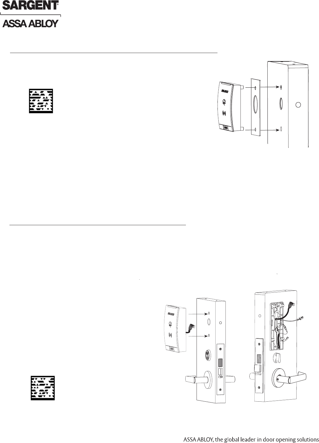
13
Outside Reader Installation
1. Orient the reader so the HID logo is at the bottom
and the lens is at the top.
2. Feed the ribbon cable through the door (from out
side to inside).
3. Install the reader to the outside of door by aligning
the mounting posts with the door preparation holes.
Hold the reader in position with hand.
4. While gently pressing upward on the outside reader,
tighten the (2) through bolts on the inside of the door to
secure the reader.
HID Reader
Outside of Door Inside of Door
Fig. 13A Fig. 13B
Gasket required for exterior doors (not required for fire rating). Figure 12.
1. Place the gasket on the on the reader posts and ensure the shape is
aligned with the edge of the reader.
12
Gasket Installation (Optional P/N 52-1332)
Fig. 12
Scan this Microsoft® Tag using your mobile phone
to see a video of this installation step. The Microsoft
Tag mobile app is required to scan the Tag.
Download the free mobile app at http://gettag.mobi
Scan this Microsoft® Tag using your mobile phone
to see a video of this installation step. The Microsoft
Tag mobile app is required to scan the Tag.
Download the free mobile app at http://gettag.mobi
Preliminary
8/05/12
1-800-810-WIRE • www.sargentlock.com • A8122B 13
Copyright © 2012, Sargent Manufacturing Company, an ASSA ABLOY Group company. All rights reserved.
Reproductions in whole or in part without express written permission of Sargent Manufacturing Company is prohibited.
IN100 Mortise Lock
14
Configuring RX Switch Handing
1. Each lever handle has a sensor installed but only the inside lever is
utilized for RX sensing.
2. To properly configure the RX functionality, connect the terminals as
indicated below:
RH or RHRB door handing (blue to blue)
LH or LHRB door handing (yellow to blue)
3. Note: Factory default is blue to blue (right hand lock).
IMPORTANT: grasp each connector firmly before separating.
Do not pull wires apart.
Wire harness
Wire harness
DPS
Lock
body
wiring
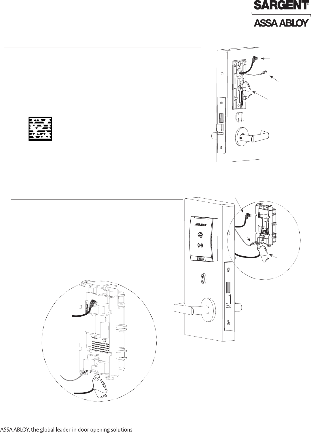
15
Battery Housing Wiring
1. Connect the outside reader ribbon cable to the top of the
battery housing (See Fig.15B for detail).
2. Connect the DPS wire to the 3-wire header at the lower
left corner of the PCB.
3. Connect the lock body harness to the 5-wire header at
the lower right corner of the PCB.
IMPORTANT: Confirm the correct connector orientation
prior to assembly. Do not force connectors
Note: If the HID wire harness must be twisted to connect to
the battery housing the HID reader has been installed upside
down. Turn the HID reader right side up and reinstall, then
connect.
Lock
body
wiring
DPS
Fig. 15A
Fig. 15B
Inside of Door
Fig. 14
Scan this Microsoft® Tag using your mobile
phone to see a video of this installation
step. The Microsoft Tag mobile app is
required to scan the Tag. Download the free
mobile app at http://gettag.mobi
Preliminary
14 1-800-810-WIRE • www.sargentlock.com • A8122B
Copyright © 2012, Sargent Manufacturing Company, an ASSA ABLOY Group company. All rights reserved.
Reproductions in whole or in part without express written permission of Sargent Manufacturing Company is prohibited.
8/050/12
IN100 Mortise Lock
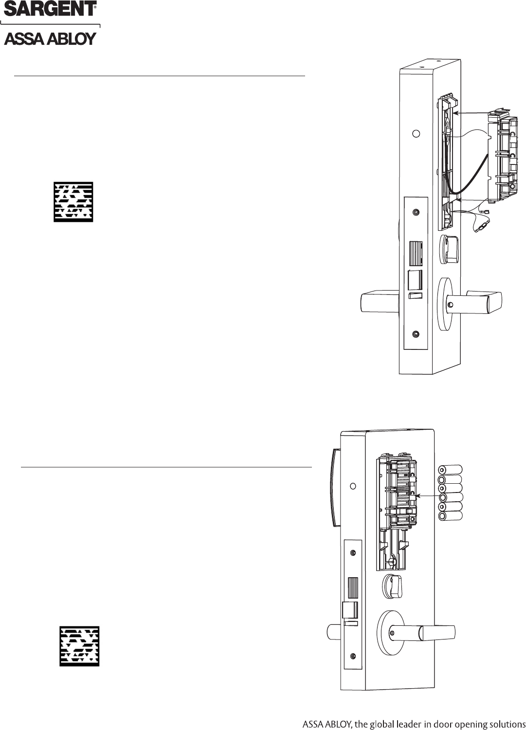
16
Battery Housing Installation
1. Position the DPS and harness below the tabs of the
mounting plate.
2. Align the tabs of the battery housing with the tabs of the
mounting plate. Push down.
3. Lightly press the lock harness to assemble.
4. Snap battery compartment into position.
Fig. 16
17
Battery Installation
1. Place (6) “AA” alkaline batteries in the compartment, being
careful to align polarity properly.
2. After batteries are installed an audible “beep” will sound, the
lock motor will cycle. Refer to page 18, section “Lock Self
Test LED Indication”, for proper power up LED indications.
Fig. 17
Inside of Door
Inside of Door
Scan this Microsoft® Tag using your mobile phone
to see a video of this installation step. The Microsoft
Tag mobile app is required to scan the Tag.
Download the free mobile app at http://gettag.mobi
Scan this Microsoft® Tag using your mobile phone
to see a video of this installation step. The Microsoft
Tag mobile app is required to scan the Tag.
Download the free mobile app at http://gettag.mobi
Preliminary
8/05/12
1-800-810-WIRE • www.sargentlock.com • A8122B 15
Copyright © 2012, Sargent Manufacturing Company, an ASSA ABLOY Group company. All rights reserved.
Reproductions in whole or in part without express written permission of Sargent Manufacturing Company is prohibited.
IN100 Mortise Lock
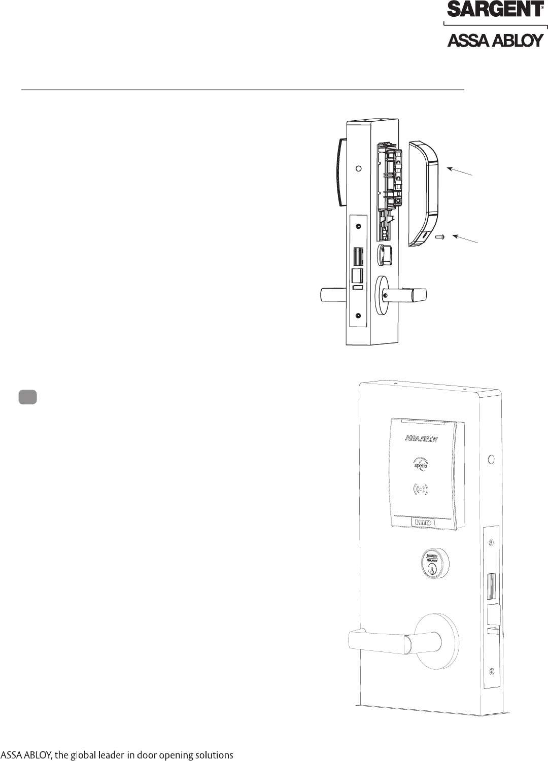
18
Inside Cover Installation
1. Assemble cover by hooking top edge on inside
mounting plate.
2. Carefully press bottom of cover toward door without
pinching any wires.
3. Secure the cover utilizing a 1/8” security Allen wrench.
Fig. 18
Inside
Cover
1/8” Security
Allen Screw
Inside of Door
For battery replacement:
When replacing the (6) “AA” alkaline batteries in the
compartment, please note batteries must be replaced within 5
minutes to prevent the internal clock from becoming inaccurate.
Maintenance
7
Preliminary
16 1-800-810-WIRE • www.sargentlock.com • A8122B
Copyright © 2012, Sargent Manufacturing Company, an ASSA ABLOY Group company. All rights reserved.
Reproductions in whole or in part without express written permission of Sargent Manufacturing Company is prohibited.
8/050/12
IN100 Mortise Lock
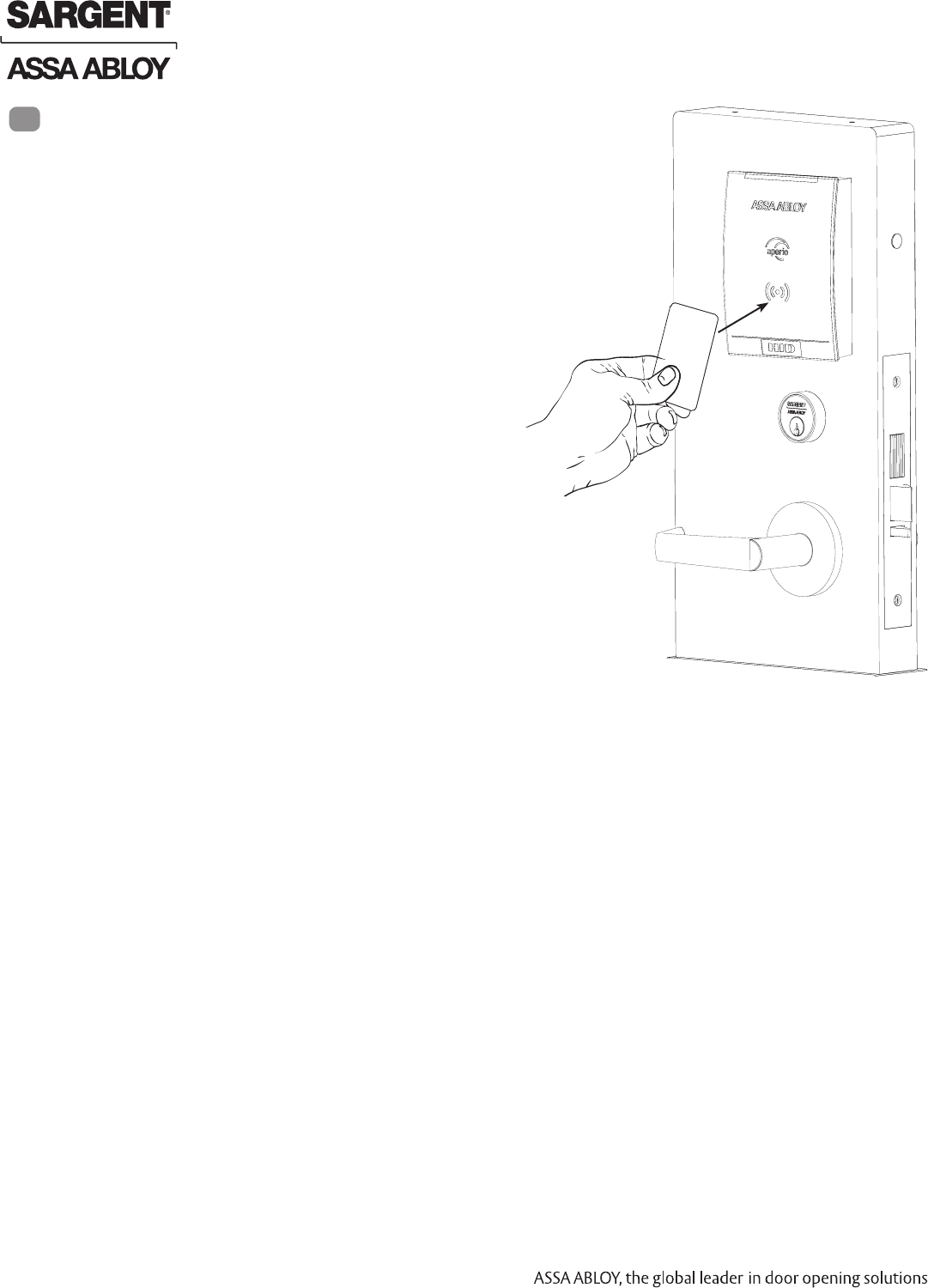
For 7976- and 7978-function mortise locks with cylinders:
1. Insert key into cylinder and rotate.
There should be no friction against lock case, wire harness or
any other obstructions.
2. Check that the key retracts the latch:
the key should rotate freely.
3. Throw the deadbolt (if present): Check that the
key retracts both the deadbolt and the latch.
4. Try the inside lever:
Ensure it retracts latch and deadbolt (if provided).
5. Present a valid iCLASS or 125 kHz prox credential to unlock
outside lever and retract latch.
Note: The credential should approach the
inscription on the reader as indicated to ensure the
credential is read properly. Do not wave credential.
Operational Check
8
Preliminary
8/05/12
1-800-810-WIRE • www.sargentlock.com • A8122B 17
Copyright © 2012, Sargent Manufacturing Company, an ASSA ABLOY Group company. All rights reserved.
Reproductions in whole or in part without express written permission of Sargent Manufacturing Company is prohibited.
IN100 Mortise Lock
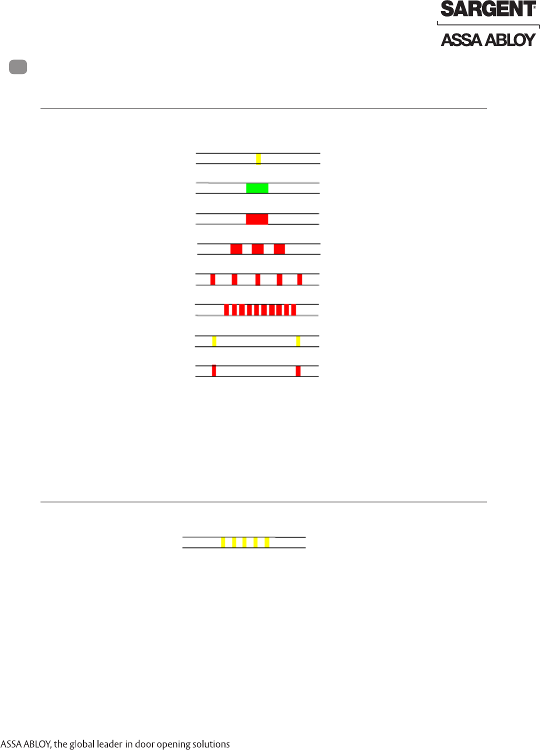
Lock LED Indications
9
The lock has three LEDs that support an optical scheme with red, yellow and green.
The indication scheme is described by the figures below:
Card read (configurable)
Access granted, EAC offline or online
Access denied, EAC online
Access denied, EAC offline
One yellow flash (.25 seconds)
One green flash (1 second)
One red flash (1 second)
Three red flashes (.5 second each)
Continuous red flashes blocked when closing
(.125 seconds every 1 second)
Ten red flashes (.125 seconds each),
maintenance required; repeated if lock can’t
close
Continuous yellow flashes (.25 seconds every
5 seconds)
Continuous red flashes, (.25 seconds every 5
seconds)
Fig. Lock Normal operation LED indication
1
Lock Normal Operation LED indication
2
Lock Maintenance LED Indication
Some special LED indication schemes are used during lock maintenance actions:
Enter configuration
mode Five yellow flashes (.125 seconds each)
Fig. Lock maintenance LED indication
Lock mechanism is blocked when
closing
Error in lock, maintenance required
Time to replace the battery
Battery reached end of life, lock
disabled
NOTE: Ensure the tamper switch activator does not fall out of the cover during assembly.
A tamper event message will be sent to the EAC panel if tamper is enabled. The “Error in
lock” indication is also shown instead of the POST flashes if the battery is not accepted as
new after a power-on-reset.
Preliminary
18 1-800-810-WIRE • www.sargentlock.com • A8122B
Copyright © 2012, Sargent Manufacturing Company, an ASSA ABLOY Group company. All rights reserved.
Reproductions in whole or in part without express written permission of Sargent Manufacturing Company is prohibited.
8/050/12
IN100 Mortise Lock
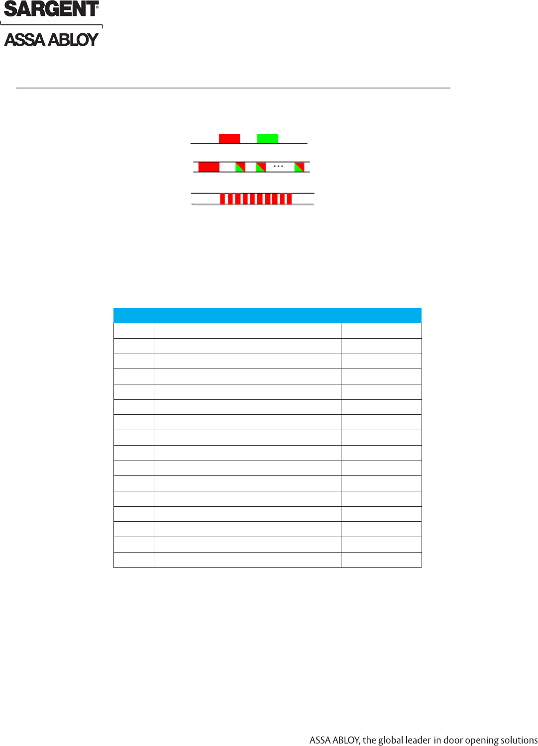
3
Lock Self Test LED Indication
After replacing the battery, a Power On Self Test (POST) is performed. The result is indicated
using a series of red and green LED flashes as is described by the figure below:
Fig. Lock POST LED indication
The first flash is always red. If the POST fails, the color of the 16 trailing flashes indicate the
status of each individual test as described by the following table:
Blink Meaning if Red Code in Event Log
2 Main board firmware corrupt 0x0001
3 Override list corrupt 0x0002
4 Production data corrupt 0x0004
5 Security data corrupt 0x0008
6 Configuration data corrupt 0x0010
7 Battery power low 0x0020
8 RFID reader circuit error 0x0040
9 Voltage regulator error 0x0080
10 Card detection circuit error 0x0100
11 Secure area communication error 0x0200
12 Secure area memory corrupt 0x0400
13 Secure area sensor or motor error 0x0800
14 Radio modem communication error 0x1000
15 Radio modem memory corrupt 0x2000
16 Radio modem configuration error 0x4000
17 Radio modem RF circuit error 0x8000
NOTE: If the battery is not accepted as new after a power on reset, no POST is performed.
Instead, the 10 quick red flashes used to indicate Error in lock is shown.
One red, one green flash (1 second each)
One red flash followed by 16 red or green
flashes (.5 seconds each)
10 red flashes.
Good POST
Bad POST
The “Error in lock” indication is also
shown instead of the POST flashes
if the battery is not accepted as new
after a power-on-reset.
Preliminary

Notes
The global leader in door opening solutions
Preliminary

SARGENT Manufacturing
100 Sargent Drive
New Haven, CT 06511 USA
800-810-WIRE (9473) • www.sargentlock.com
Founded in the early 1800s, SARGENT® is a market leader in locksets, cylinders, door closers, exit devices,
electro-mechanical products and access control systems for new construction, renovation, and replacement applications.
The company’s customer base includes commercial construction, institutional, and industrial markets.
Copyright © 2012, Sargent Manufacturing Company, an ASSA ABLOY Group company. All rights reserved.
Reproduction in whole or in part without the express written permission of Sargent Manufacturing Company is prohibited.
ASSA ABLOY is the global leader in door opening solutions, dedicated to
satisfying end-user needs for security, safety and convenience. A8122B - 8/12
Preliminary