ASUSTeK Computer F9AWGE780 NOTEBOOK P.C. User Manual AD5EA4E5A4E2A5552E706466
ASUSTeK Computer Inc NOTEBOOK P.C. AD5EA4E5A4E2A5552E706466
Contents
- 1. USERS MANUAL 1
- 2. USERS MANUAL 2
USERS MANUAL 1
Notebook PC
Hardware User’s Manual
ASUS WIDE SCREEN NOTEBOOK
OFFON
E3232 / May 2007

2
Contents
Table of Contents
Table of Contents
1. Introducing the Notebook PC
About This User’s Manual .......................................................................................... 6
Notes For This Manual...........................................................................................6
Preparing your Notebook PC...................................................................................... 9
2. Knowing the Parts
Top Side....................................................................................................................12
Bottom Side..............................................................................................................14
Left Side ...................................................................................................................16
Right Side.................................................................................................................18
Rear Side..................................................................................................................20
Front Side.................................................................................................................21
3. Getting Started
Power System .......................................................................................................... 24
Using AC Power...................................................................................................24
Using Battery Power ............................................................................................ 25
Battery Care.........................................................................................................25
Powering ON the Notebook PC ........................................................................... 26
The Power-On Self Test (POST)..........................................................................26
Checking Battery Power ......................................................................................27
Charging the Battery Pack................................................................................... 27
Restarting or Rebooting....................................................................................... 28
Powering OFF......................................................................................................28
Special Keyboard Functions..................................................................................... 29
Colored Hot Keys.................................................................................................29
Microsoft Windows Keys......................................................................................31
Keyboard as a Numeric Keypad ......................................................................... 31
Keyboard as Cursors ........................................................................................... 31
Switches and Status Indicators ................................................................................ 32
Switches...............................................................................................................32
Status Indicators .................................................................................................. 33
Multimedia Control Keys (on selected models) ...................................................34

3
Contents
Table of Contents (cont.)
(continued on next page)
4. Using the Notebook PC
Pointing Device......................................................................................................... 36
Using the Touchpad ............................................................................................. 36
Touchpad Usage Illustrations............................................................................... 37
Caring for the Touchpad....................................................................................... 38
Automatic Touchpad Disabling (on selected models) ......................................... 38
Storage Devices ....................................................................................................... 39
Expansion Card ................................................................................................... 39
Optical Drive ........................................................................................................ 40
Flash Memory Card Reader ................................................................................ 42
Hard Disk Drive.................................................................................................... 43
Memory (RAM)..................................................................................................... 44
Connections.............................................................................................................. 45
Modem Connection.............................................................................................. 45
Network Connection ............................................................................................ 46
Wireless LAN Connection (on selected models) ................................................. 47
Intel PROSet (3945) Wireless LAN (on selected models) ................................... 48
ASUS Wireless LAN (on selected models)......................................................... 49
Windows Wireless Network Connection .............................................................. 50
Bluetooth Wireless Connection (on selected models) ......................................... 51
Power Management Modes...................................................................................... 52
Full Power Mode & Maximum Performance ........................................................ 52
ACPI..................................................................................................................... 52
Suspend Mode..................................................................................................... 52
Power Savings..................................................................................................... 52
Power State Summary......................................................................................... 53
Thermal Power Control........................................................................................ 53
Stand by and Hibernate ....................................................................................... 54
Fingerprint Scanner (on selected models)................................................................ 55
Fingerprint Login.................................................................................................. 56
Trusted Platform Module (TPM) (on selected models) ........................................ 57

4
Contents
Table of Contents (cont.)
Appendix
Optional Accessories
Optional Connections
Operating System and Software
System BIOS Settings
Common Problems and Solutions
Windows XP Software Recovery
NTFS Converter (Windows XP only)
Glossary
Declarations and Safety Statements
Notebook PC Information

5
1. Introducing the Notebook PC
About This User’s Manual
Notes For This Manual
Safety Precautions
Preparing your Notebook PC

6
1 Introducing the Notebook PC
About This User’s Manual
You are reading the Notebook PC User’s Manual. This User’s Manual provides informa-
tion on the various components in the Notebook PC and how to use them. The following
are major sections of this User’s Manuals:
1. Introducing the Notebook PC
Introduces you to the Notebook PC and this User’s Manual.
2. Knowing the Parts
Gives you information on the Notebook PC’s components.
3. Getting Started
Gives you information on getting started with the Notebook PC.
4. Using the Notebook PC
Gives you information on using the Notebook PC’s components.
5. Appendix
Introduces you to optional accessories and gives additional information.
Notes For This Manual
A few notes and warnings in bold are used throughout this guide that you should be aware of in order
to complete certain tasks safely and completely. These notes have different degrees of importance as
described below:
NOTE: Tips and information for special situations.
TIP: Tips and useful information for completing tasks.
IMPORTANT! Vital information that must be followed to prevent damage to data, com-
ponents, or persons.
WARNING! Important information that must be followed for safe operation.
Text enclosed in < > or [ ] represents a key on the keyboard; do not actually type the
< > or [ ] and the enclosed letters.
< >
[ ]
7
Introducing the Notebook PC 1
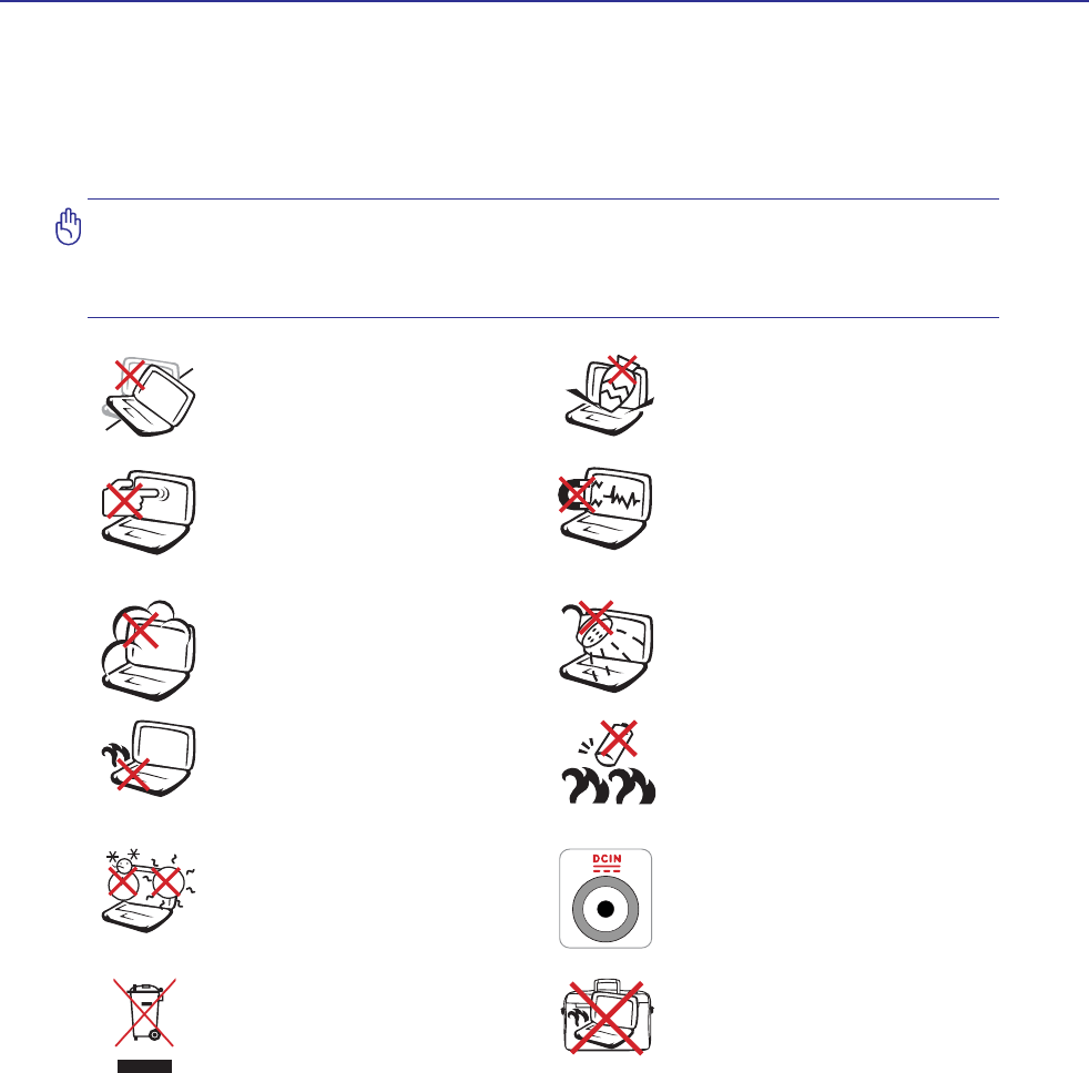
Safety Precautions
The following safety precautions will increase the life of the Notebook PC. Follow all precautions and
LQVWUXFWLRQV([FHSWDVGHVFULEHGLQWKLVPDQXDOUHIHUDOOVHUYLFLQJWRTXDOLÀHGSHUVRQQHO'RQRWXVH
GDPDJHGSRZHUFRUGVDFFHVVRULHVRURWKHUSHULSKHUDOV'RQRWXVHVWURQJVROYHQWVVXFKDVWKLQQHUV
benzene, or other chemicals on or near the surface.
IMPORTANT! Disconnect the AC power and remove the battery pack(s) before clean-
ing. Wipe the Notebook PC using a clean cellulose sponge or chamois cloth dampened
with a solution of nonabrasive detergent and a few drops of warm water and remove
any extra moisture with a dry cloth.
DO NOT expose to or use near liquids,
rain, or moisture. DO NOT use the
modem during an electrical storm.
DO NOT expose to dirty or dusty en-
vironments. DO NOT operate during
a gas leak.
SAFE TEMP: This Notebook PC
should only be used in environments
with ambient temperatures between
5°C (41°F) and 35°C (95°F)
Battery safety warning:
DO NOT WKURZWKHEDWWHU\LQÀUH
DO NOT short circuit the contacts.
DO NOT disassemble the battery.
DO NOT expose to strong magnetic
RUHOHFWULFDOÀHOGV
DO NOT place on uneven or unstable
work surfaces. Seek servicing if the
casing has been damaged.
DO NOT place or drop objects on top
and do not shove any foreign objects
into the Notebook PC.
DO NOT press or touch the display
SDQHO 'R QRW SODFH WRJHWKHU ZLWK
small items that may scratch or enter
the Notebook PC.
DO NOT leave the Notebook PC on
your lap or any part of the body in
order to prevent discomfort or injury
from heat exposure.
DO NOT throw the Notebook PC
in municipal waste. Check local
regulations for disposal of electronic
products.
DO NOT carry or cover a Notebook
PC that is powered ON with any ma-
terials that will reduce air circulation
such as a carrying bag.
INPUT RATING: Refer to the rating
label on the bottom of the Notebook
PC and be sure that your power adapter
complies with the rating.

8
1 Introducing the Notebook PC
CAUTION! There are three main types of airport security devices: X-ray machines
(used on items placed on conveyor belts), magnetic detectors (used on people walking
through security checks), and magnetic wands (hand-held devices used on people or
individual items). You can send your Notebook PC and diskettes through airport X-ray
machines. However, it is recommended that you do not send your Notebook PC or
diskettes through airport magnetic detectors or expose them to magnetic wands.
Charge Your Batteries
If you intend to use battery power, be sure to fully charge your battery pack and any optional battery
packs before going on long trips. Remember that the power adapter charges the battery pack as long as
it is plugged into the computer and an AC power source. Be aware that it takes much longer to charge
the battery pack when the Notebook PC is in use.
Airplane Precautions
Contact your airline if you want to use the Notebook PC on the airplane. Most airlines will have restric-
tions for using electronic devices. Most airlines will allow electronic use only between and not during
takeoffs and landings.
Transportation Precautions
To prepare the Notebook PC for transport, you should turn it OFF and disconnect all external peripher-
als to prevent damage to the connectors. The hard disk drive’s head retracts when the power is turned
OFF to prevent scratching of the hard disk surface during transport. Therefore, you should not transport
the Notebook PC while the power is still ON. Close the display panel and check that it is latched securely
in the closed position to protect the keyboard and display panel.
CAUTION: The Notebook PC’s surface is easily dulled if not properly cared for. Be
careful not to rub or scrape the Notebook PC surfaces.
Cover Your Notebook PC
Purchase a carrying bag to protect the Notebook PC from dirt, water, shock, and scratches.
9
Introducing the Notebook PC 1
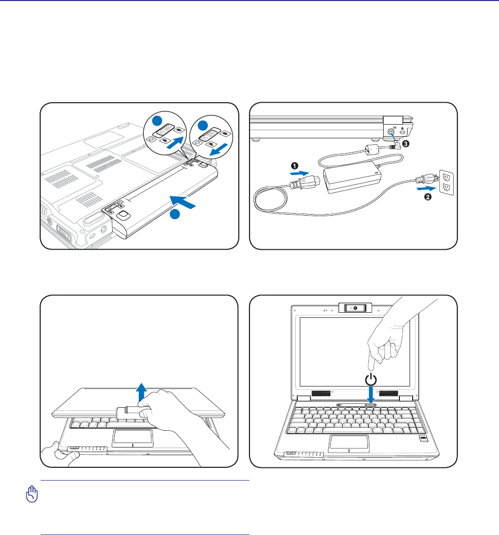
Preparing your Notebook PC
These are only quick instructions for using your Notebook PC. Read the later pages for detailed informa-
tion on using your Notebook PC.
1. Install the battery pack 2. Connect the AC Power Adapter
Press the power button and release.
(In Windows XP, this button can also be used to
safely turn OFF the Notebook PC.)
IMPORTANT! When opening, do not force
the display panel down to the table or else
the hinges may break! Never lift the Note-
book PC by the display panel!
OFF ON
ASUS WIDE SCREEN NOTEBOOK
2
31
1.3
MEGA
PIXELS
OFF ON
ASUS WIDE SCREEN NOTEBOOK
3. Open the Display Panel 4. Turn ON the Notebook PC

10
1 Introducing the Notebook PC

11
2. Knowing the Parts
Basic sides of the Notebook PC
NOTE: Photos and icons in this manual are used for artistic purposes only and do not
show what is actually used in the product itself.
12
2 Knowing the Parts
1
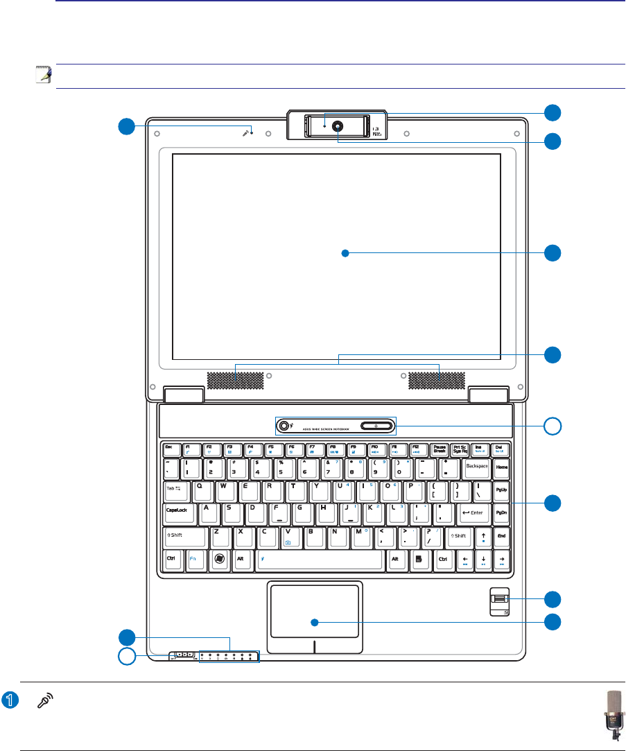
Top Side
Refer to the diagram below to identify the components on this side of the Notebook PC.
NOTE: The keyboard will be different for each territory.
4
5
7
8
3
12
10
9
6
6
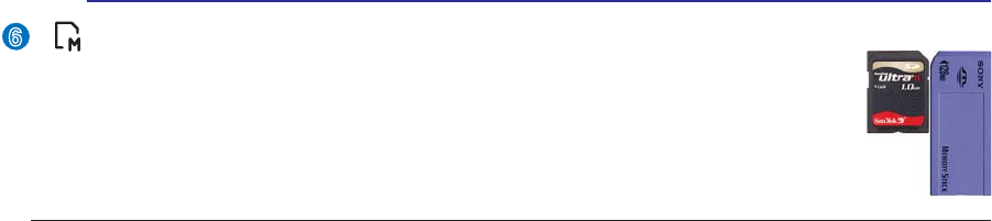
Microphone (Built-in)
The built-in mono microphone can be used for video conferencing, voice narrations, or simple
audio recordings.
13
Knowing the Parts 2
2
3
4
5
6
7
8
9
10
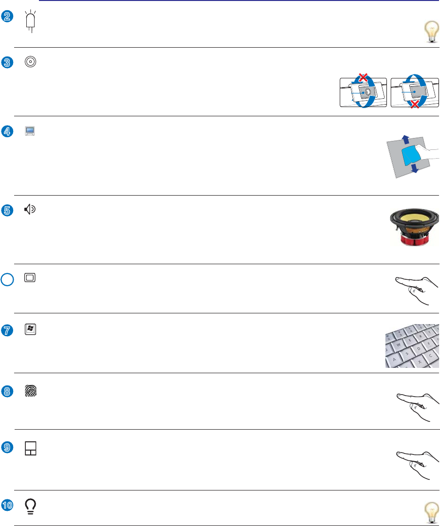
Instant Keys
Instant keys allow you to launch frequently used applications with one push of a button.
'HWDLOVare described in section 3.
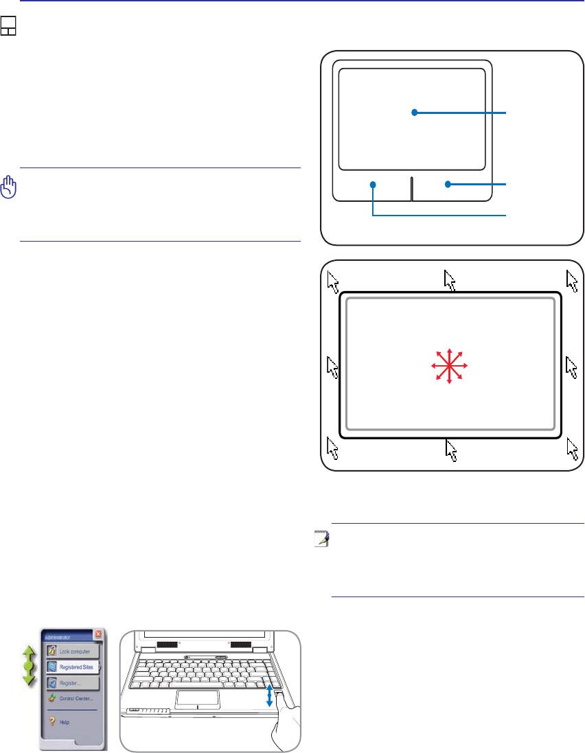
Touchpad and Buttons
The touchpad with its buttons is a pointing device that provides the same functions as a
desktop mouse. A software-controlled scrolling function is available after setting up the
included touchpad utility to allow easy Windows or web navigation.
Audio Speakers
The built-in stereo speaker system allows you to hear audio without additional attachments.
The multimedia sound system features an integrated digital audio controller that produces
rich, vibrant sound (results improved with external stereo headphones or speakers). Audio
features are software controlled.
Display Panel
The display panel functions the same as a desktop monitor. The Notebook PC uses an
DFWLYHPDWUL[7)7/&'ZKLFKSURYLGHVH[FHOOHQWYLHZLQJOLNHWKDWRIGHVNWRSPRQLWRUV
8QOLNHGHVNWRSPRQLWRUVWKH/&'SDQHOGRHVQRWSURGXFHDQ\UDGLDWLRQRUÁLFNHULQJ
so it is easier on the eyes. Use a soft cloth without chemical liquids (use plain water if
necessary) to clean the display panel.
Status Indicators (front)
Status indicators represent various hardware/software conditions. See indicator details in section 3.
Camera Indicator
The camera indicator shows when the built-in camera is in use. The camera may be auto-activated
by supported software.
Keyboard
The keyboard provides full-sized keys with comfortable travel (depth at which the keys
can be depressed) and palm rest for both hands. Two Windows function keys are provided
to help ease navigation in the Windows operating system.
Fingerprint Scanner (on selected models)
7KHÀQJHUSULQWVFDQQHUDOORZVXVHRIVHFXULW\VRIWZDUHXVLQJ\RXUÀQJHUSULQWDV\RXULGHQ-
WLÀFDWLRQNH\
Multi-Position Camera (on selected models)
The built-in camera allows picture taking or video recording. Can be used with
video conferencing and other interactive applications. CAUTION: The cam-
HUDFDQEHDGMXVWHGIDFLQJIRUZDUGRUIDFLQJEDFNZDUGEXWFDQRQO\ÁLS
through the bottom. Do not rotate the camera upward past 35 degrees.
Back
Front
14
2 Knowing the Parts
Bottom Side
Refer to the diagram below to identify the components on this side of the Notebook PC.
5
6
3
4
1
2
WARNING! The bottom of the Notebook PC can get very hot. Be careful when handling
the Notebook PC while it is in operation or recently been in operation. High tempera-
tures are normal during charging or operation. Do not use on soft surfaces such as
beds or sofas which may block the vents. DO NOT PUT THE NOTEBOOK PC ON YOUR
LAP OR OTHER PARTS OF THE BODY TO AVOID INJURY FROM THE HEAT.
NOTE: The bottom side may vary in appearance depending on model.
NOTE: The battery pack size will vary depending on model.
15
Knowing the Parts 2
2
3
4
1
6
5
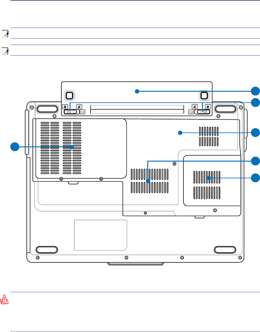
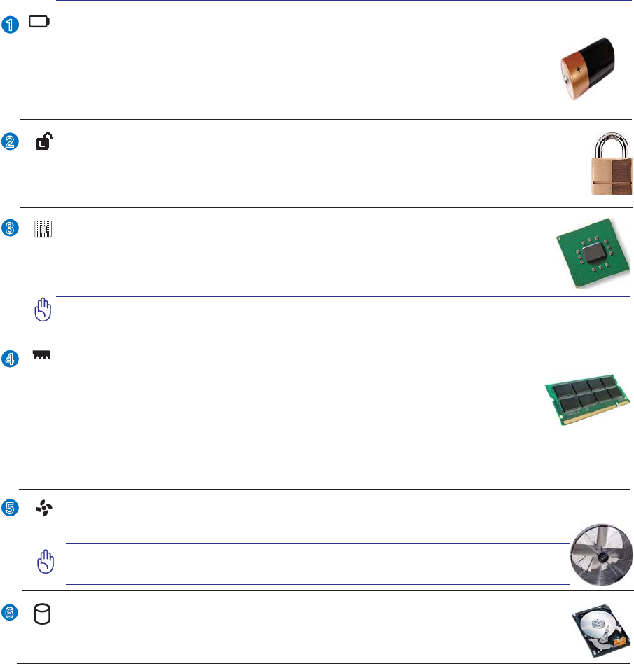
Battery Lock - Spring
The spring battery lock is used to keep the battery pack secured. When the battery pack is in-
serted, it will automatically lock. To remove the battery pack, this spring lock must be held in
the unlocked position.
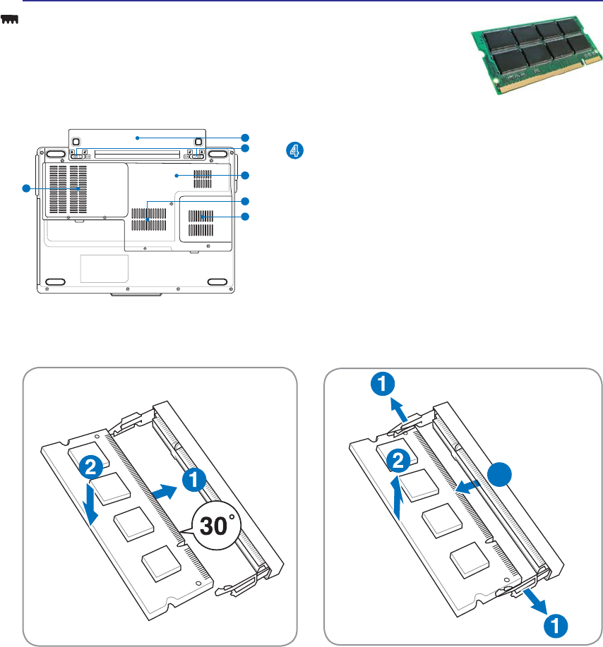
Memory (RAM) Compartment
The memory compartment provides expansion capabilities for additional memory. Addi-
tional memory will increase application performance by decreasing hard disk access. The
%,26DXWRPDWLFDOO\GHWHFWVWKHDPRXQWRIPHPRU\LQWKHV\VWHPDQGFRQÀJXUHV&026
accordingly during the POST (Power-On-Self-Test) process. There is no hardware or
software (including BIOS) setup required after the memory is installed. Visit an authorized service center
or retailer for information on memory upgrades for your Notebook PC. Only purchase expansion modules
from authorized retailers of this Notebook PC to ensure maximum compatibility and reliability.
Central Processor Unit (CPU) Compartment
Some Notebook PC models feature a socketed-processor design to allow upgrading to faster
processors in the future. Some models feature a ULV design for compactness and may not
be upgraded. Visit an authorized service center or retailer for information on upgrades.
WARNING! End-user removal of the CPU or hard disk drive will void the warranty.
Hard Disk Drive Compartment
The hard disk drive is secured in a compartment. Hard disk drive upgrades are to be done
by authorized service centers or dealers only.
Battery Pack
The battery pack is automatically charged when the Notebook PC is connected to an AC
power source and maintains power to the Notebook PC when AC power is not connected.
This allows use when moving temporarily between locations. Battery time varies by usage
DQGE\WKHVSHFLÀFDWLRQVIRUWKLV1RWHERRN3&7KHEDWWHU\SDFNFDQQRWEHGLVDVVHPEOHG
and must be purchased as a single unit.
Cooling Fan
The cooling fan removes excess heat depending on temperature threshold settings.
IMPORTANT! Make sure that paper, books, clothing, cables, or other objects
do not block any of the air vents or else overheating may occur.
16
2 Knowing the Parts
Left Side
Refer to the diagram below to identify the components on this side of the Notebook PC.
2
3
4
1
5
1 2 3
4 5
6
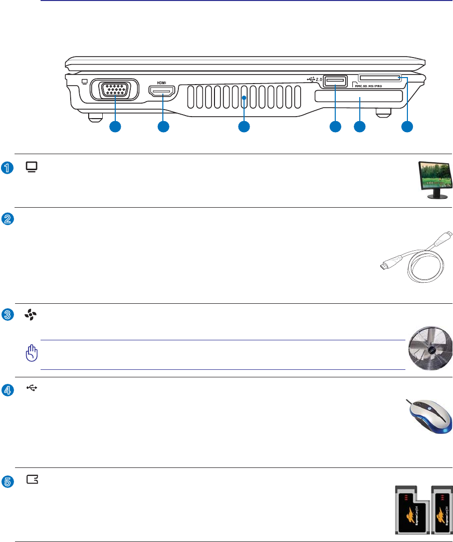
ExpressCard Slot
One 26pin Express card slot is available to support one ExpressCard/34mm or one
ExpressCard/54mm expansion card. This new interface is faster by using a serial bus
supporting USB 2.0 and PCI Express instead of the slower parallel bus used in the PC
card slot. (Not compatible with previous PCMCIA cards.)
Display (Monitor) Output
7KHSLQ'VXEPRQLWRUSRUWVXSSRUWVDVWDQGDUG9*$FRPSDWLEOHGHYLFHVXFKDVDPRQLWRU
or projector to allow viewing on a larger external display.
2.0
USB Port (2.0/1.1)
The USB (Universal Serial Bus) port is compatible with USB 2.0 or USB 1.1 devices such as
keyboards, pointing devices, cameras, hard disk drives, printers, and scanners connected in a
series up to 12Mbits/sec (USB 1.1) and 480Mbits/sec (USB 2.0). USB allows many devices to
run simultaneously on a single computer, with some peripherals acting as additional plug-in sites or
hubs. USB supports hot-swapping of devices so that most peripherals can be connected or disconnected
without restarting the computer.
Air Vents
The air vents allow cool air to enter and warm air to exit the Notebook PC.
IMPORTANT! Make sure that paper, books, clothing, cables, or other objects
do not block any of the air vents or else overheating may occur.
HDMI Port
+'0,+LJK'HÀQLWLRQ0XOWLPHGLD,QWHUIDFHLVDQXQFRPSUHVVHGDOOGLJLWDODXGLR
YLGHRLQWHUIDFHEHWZHHQDQ\DXGLRYLGHRVRXUFHVXFKDVDVHWWRSER['9'SOD\HU
and A/V receiver and an audio and/or video monitor, such as a digital television
'796XSSRUWVVWDQGDUGHQKDQFHGRUKLJKGHÀQLWLRQYLGHRSOXVPXOWLFKDQQHO
GLJLWDODXGLRRQDVLQJOHFDEOH,WWUDQVPLWVDOO$76&+'79VWDQGDUGVDQGVXSSRUWV
channel digital audio, with bandwidth to spare to accommodate future enhancements or requirements.
HDMI
17
Knowing the Parts 2
6
Flash Memory Slot
Normally a PCMCIA or USB memory card reader must be purchased separately in
order to use memory cards from devices such as digital cameras, MP3 players, mobile
SKRQHVDQG3'$V7KLV1RWHERRN3&KDVDEXLOWLQPHPRU\FDUGUHDGHUWKDWFDQUHDG
PDQ\ÁDVKPHPRU\FDUGVDVVSHFLÀHGODWHULQWKLVPDQXDO7KHEXLOWLQPHPRU\FDUGUHDGHULV
not only convenient, but also faster than most other forms of memory card readers because it
utilizes the high-bandwidth PCI bus.
18
2 Knowing the Parts
Right Side
Refer to the diagram below to identify the components on this side of the Notebook PC.
2
3
1
4
2 3 41 5 6 7 8
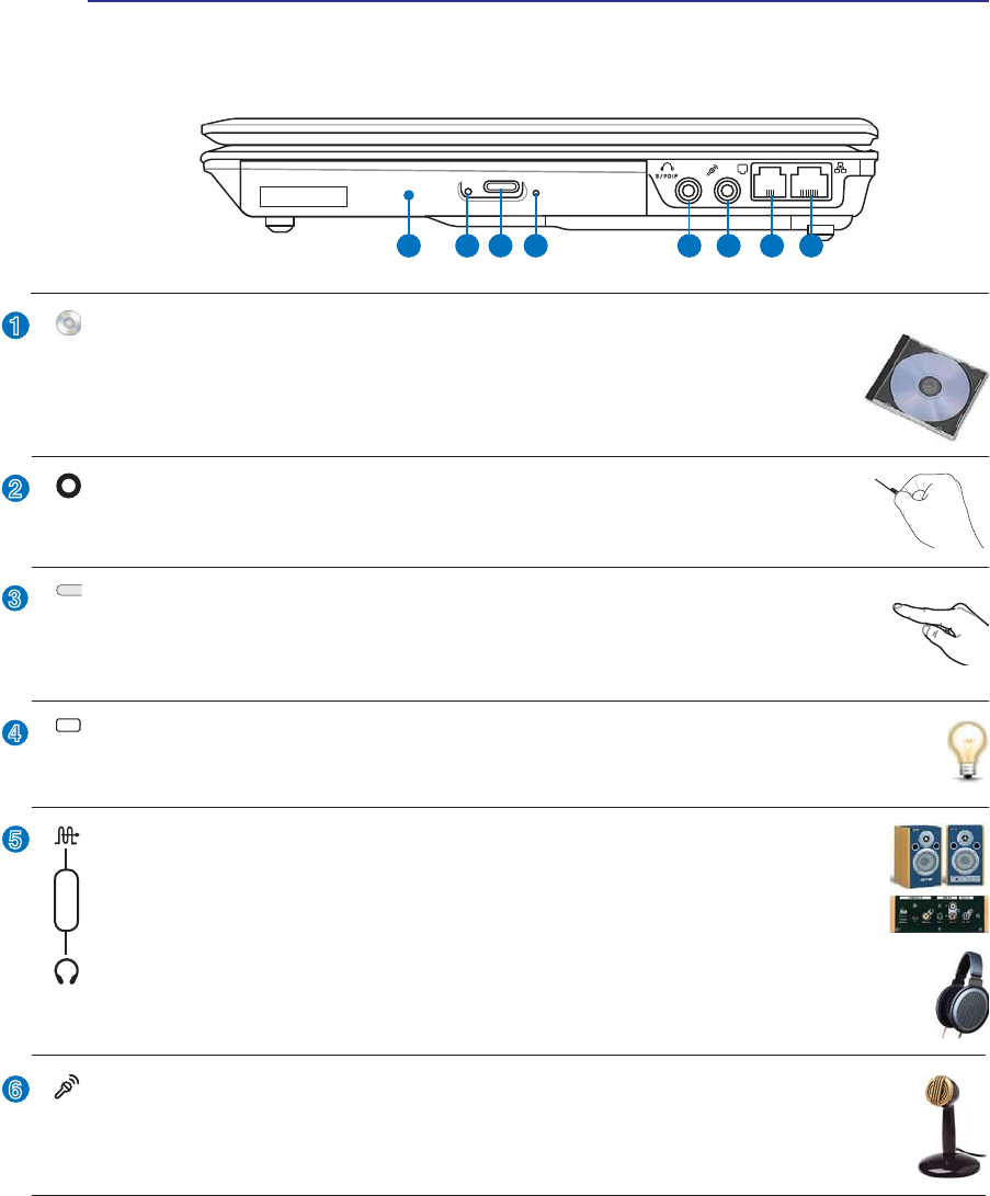
Optical Drive Electronic Eject
The optical drive eject has an electronic eject button for opening the tray. You can also eject
the optical drive tray through any software player or by right clicking the optical drive in
Windows™ “My Computer.”
Optical Drive Emergency Eject (location varies by model)
The emergency eject is used to eject the optical drive tray in case the electronic eject does
QRWZRUN'RQRWXVHWKHHPHUJHQF\HMHFWLQSODFHRIWKHHOHFWURQLFHMHFW
5
6
Optical Drive Activity Indicator (location varies by model)
The optical drive activity indicator shows when data is being transferred by the optical disk drive.
This indicator will light in proportion to the data size transferred.
Optical Drive
The Notebook PC comes in various models with different optical drives. The Notebook
3&·VRSWLFDOGULYHPD\VXSSRUWFRPSDFWGLVFV&'DQGRUGLJLWDOYLGHRGLVFV'9'DQG
PD\KDYHUHFRUGDEOH5RUUHZULWDEOH5:FDSDELOLWLHV6HHWKHPDUNHWLQJVSHFLÀFD-
tions for details on each model.
SPDIF Output Jack
7KLVMDFNSURYLGHVFRQQHFWLRQWR63',)6RQ\3KLOLSV'LJLWDO,QWHUIDFHFRPSOLDQWGH-
YLFHVIRUGLJLWDODXGLRRXWSXW8VHWKLVIHDWXUHWRWXUQWKH1RWHERRN3&LQWRDKLÀKRPH
entertainment system.
Headphone Output Jack
The stereo headphone jack (1/8 inch) is used to connect the Notebook PC’s audio out signal to
DPSOLÀHGVSHDNHUVRUKHDGSKRQHV8VLQJWKLVMDFNDXWRPDWLFDOO\GLVDEOHVWKHEXLOWLQVSHDNHUV
Combo
Microphone Input Jack
The mono microphone jack (1/8 inch) can be used to connect an external microphone or output
signals from audio devices. Using this jack automatically disables the built-in microphone. Use
this feature for video conferencing, voice narrations, or simple audio recordings.
19
Knowing the Parts 2
7
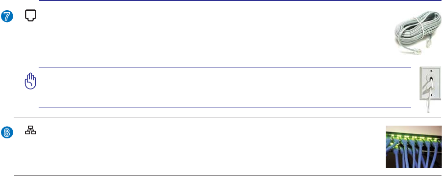
Modem Port
The RJ-11 modem port with two pins is smaller than the RJ-45 LAN port and supports
a standard telephone cable. The internal modem supports up to 56K V.90 transfers. The
built-in connector allows convenient use without additional adapters.
IMPORTANT! The built-in modem does not support the voltage used in digital
phone systems. Do not connect the modem port to a digital phone system or
else damage will occur to the Notebook PC.
LAN Port
The RJ-45 LAN port with eight pins is larger than the RJ-11 modem port and supports a
standard Ethernet cable for connection to a local network. The built-in connector allows
convenient use without additional adapters.
8
20
2 Knowing the Parts
Rear Side
Refer to the diagram below to identify the components on this side of the Notebook PC.
1 2 3 4
1
2
3
4
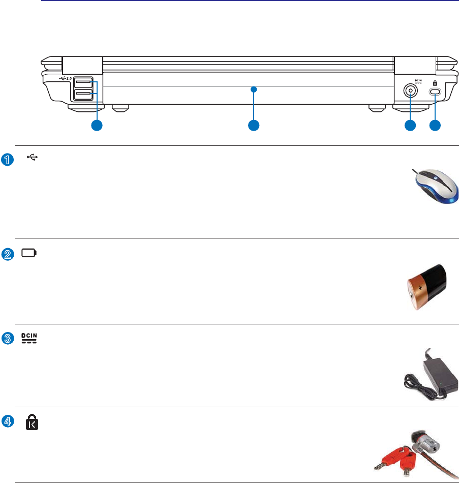
Battery Pack
The battery pack is automatically charged when the Notebook PC is connected to an AC
power source and maintains power to the Notebook PC when AC power is not connected.
This allows use when moving temporarily between locations. Battery time varies by usage
DQGE\WKHVSHFLÀFDWLRQVIRUWKLV1RWHERRN3&7KHEDWWHU\SDFNFDQQRWEHGLVDVVHPEOHG
and must be purchased as a single unit.
Power (DC) Input
7KHVXSSOLHGSRZHUDGDSWHUFRQYHUWV$&SRZHUWR'&SRZHUIRUXVHZLWKWKLVMDFN3RZHUVXS-
plied through this jack supplies power to the Notebook PC and charges the internal battery pack.
To prevent damage to the Notebook PC and battery pack, always use the supplied power
adapter. CAUTION: MAY BECOME WARM TO HOT WHEN IN USE. BE SURE
NOT TO COVER THE ADAPTER AND KEEP IT AWAY FROM YOUR BODY.
Kensington® Lock Port
The Kensington® lock port allows the Notebook PC to be secured using Kensington® com-
patible Notebook PC security products. These security products usually include a metal
FDEOHDQGORFNWKDWSUHYHQWWKH1RWHERRN3&WREHUHPRYHGIURPDÀ[HGREMHFW
Some may also include a motion detector to sound an alarm when moved.
2.0
USB Port (2.0/1.1)
The USB (Universal Serial Bus) port is compatible with USB 2.0 or USB 1.1 devices such as
keyboards, pointing devices, cameras, hard disk drives, printers, and scanners connected in a
series up to 12Mbits/sec (USB 1.1) and 480Mbits/sec (USB 2.0). USB allows many devices to
run simultaneously on a single computer, with some peripherals acting as additional plug-in sites or
hubs. USB supports hot-swapping of devices so that most peripherals can be connected or disconnected
without restarting the computer.
21
Knowing the Parts 2
Front Side
Refer to the diagram below to identify the components on this side of the Notebook PC.
1
1
Status Indicators (front)
Status indicators represent various hardware/software conditions. See indicator details in section 3.

22
3 Getting Started

23
3. Getting Started
Using AC Power
Using Battery Power
Powering ON the Notebook PC
Checking Battery Power
Restarting or Rebooting
Powering OFF the Notebook PC
Special Keyboard Functions
Switches and Status Indicators
24
3 Getting Started
IMPORTANT! Damage may occur if you use a different adapter to power the Notebook
PC or use the Notebook PC’s adapter to power other electrical devices. If there is
smoke, burning scent, or extreme heat coming from the AC-DC adapter, seek servic-
ing. Seek servicing if you suspect a faulty AC-DC adapter. You may damage both your
battery pack(s) and the Notebook PC with a faulty AC-DC adapter.
NOTE: This Notebook PC may come with either a two or three-prong plug depending
on territory. If a three-prong plug is provided, you must use a grounded AC outlet or
use a properly grounded adapter to ensure safe operation of the Notebook PC.
WARNING! THE POWER ADAPTER MAY BECOME WARM TO HOT WHEN IN USE. BE
SURE NOT TO COVER THE ADAPTER AND KEEP IT AWAY FROM YOUR BODY.
Power System
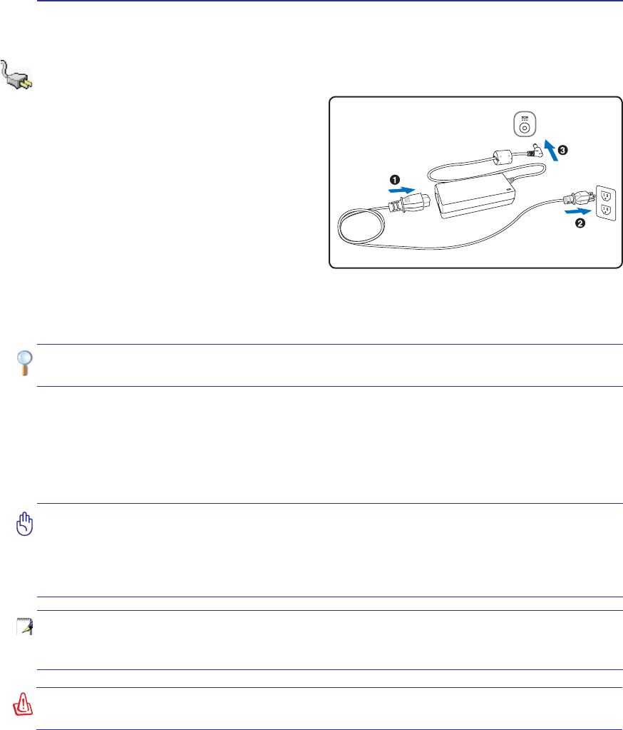
Using AC Power
The Notebook PC power is comprised of two parts,
the power adapter and the battery power system.
The power adapter converts AC power from a wall
RXWOHWWRWKH'&SRZHUUHTXLUHGE\WKH1RWHERRN
PC. Your Notebook PC comes with a universal
$&'&DGDSWHU7KDWPHDQVWKDW\RXPD\FRQQHFW
the power cord to any 100V-120V as well as 220V-
240V outlets without setting switches or using
SRZHUFRQYHUWHUV'LIIHUHQWFRXQWULHVPD\UHTXLUH
that an adapter be used to connect the provided
US-standard AC power cord to a different standard.
Most hotels will provide universal outlets to sup-
port different power cords as well as voltages. It is always best to ask an experienced traveler about AC
outlet voltages when bringing power adapters to another country.
TIP: You can buy travel kits for the Notebook PC that includes power and modem
adapters for almost every country.
:LWKWKH$&SRZHUFRUGFRQQHFWHGWRWKH$&'&FRQYHUWHUFRQQHFWWKH$&SRZHUFRUGWRDQ$&RXWOHW
SUHIHUDEO\ZLWKVXUJHSURWHFWLRQDQGWKHQFRQQHFWWKH'&SOXJWRWKH1RWHERRN3&&RQQHFWLQJWKH
$&'&DGDSWHUWRWKH$&RXWOHWÀUVWDOORZV\RXWRWHVWWKH$&RXWOHW·VSRZHUDQGWKH$&'&FRQYHUWHU
LWVHOIIRUFRPSDWLELOLW\SUREOHPVEHIRUHFRQQHFWLQJWKH'&SRZHUWRWKH1RWHERRN3&7KHSRZHULQGL-
cator on the adapter (if available) will light if the power is within accepted ranges.
25
Getting Started 3
IMPORTANT! Never attempt to remove the battery pack while the Notebook PC is
turned ON, as this may result in the loss of working data.
IMPORTANT! Only use battery packs and power adapters supplied with this Notebook
3&RUVSHFLÀFDOO\DSSURYHGE\WKHPDQXIDFWXUHURUUHWDLOHUIRUXVHZLWKWKLVPRGHORU
else damage may occur to the Notebook PC.
2
31
3
1
2
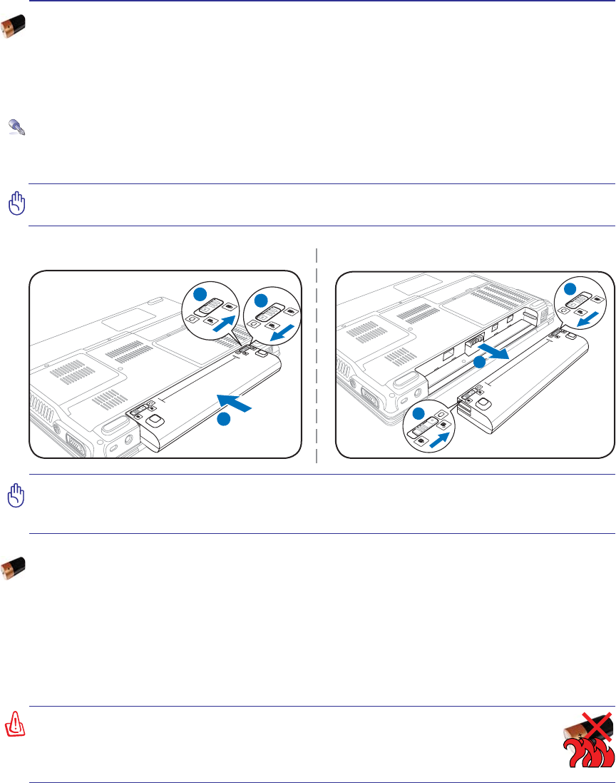
To install the battery pack: To remove the battery pack:
:$51,1*)RUVDIHW\UHDVRQV'2127WKURZWKHEDWWHU\LQÀUH'2127
short circuit the contacts, and DO NOT disassemble the battery. If there is
any abnormal operation or damage to the battery pack caused by impact,
turn OFF the Notebook PC and contact an authorized service center.
Using Battery Power
The Notebook PC is designed to work with a removable battery pack. The battery pack consists of a set
of battery cells housed together. A fully charged pack will provide several hours of battery life, which
can be further extended by using power management features through the BIOS setup. Additional battery
packs are optional and can be purchased separately through a Notebook PC retailer.
Installing and Removing the Battery Pack
Your Notebook PC may or may not have its battery pack installed. If your Notebook PC does not have
its battery pack installed, use the following procedures to install the battery pack.
Battery Care
The Notebook PC’s battery pack, like all rechargeable batteries, has a limit on the number times it can
be recharged. The battery pack’s useful life will depend on your environment temperature, humidity, and
KRZ\RXU1RWHERRN3&LVXVHG,WLVLGHDOWKDWWKHEDWWHU\EHXVHGLQDWHPSHUDWXUHUDQJHEHWZHHQÝ&
DQGÝ&Ý)DQGÝ)<RXPXVWDOVRWDNHLQWRDFFRXQWWKDWWKH1RWHERRN3&·VLQWHUQDOWHPSHUDWXUH
is higher than the outside temperature. Any temperatures above or below this range will shorten the life
of the battery. But in any case, the battery pack’s usage time will eventually decrease and a new battery
pack must be purchased from an authorized dealer for this Notebook PC. Because batteries also have a
shelf life, it is not recommended to buy extras for storing.
26
3 Getting Started
IMPORTANT! If warnings are still given during bootup after running a software disk
checking utility, you should take your Notebook PC in for servicing. Continued use
may result in data loss.
IMPORTANT! To protect the hard disk drive, always wait at least 5 seconds after turn-
ing OFF your Notebook PC before turning it back ON.
127(%HIRUHERRWXSWKHGLVSOD\SDQHOÁDVKHVZKHQWKHSRZHULVWXUQHG217KLVLV
part of the Notebook PC’s test routine and is not a problem with the display.
WARNING! DO NOT carry or cover a Notebook PC that is powered ON with any materi-
als that will reduce air circulation such as a carrying bag.
Powering ON the Notebook PC
The Notebook PC’s power-ON message appears on the screen when you turn it ON. If necessary, you
may adjust the brightness by using the hot keys. If you need to run the BIOS Setup to set or modify the
V\VWHPFRQÀJXUDWLRQSUHVV>)@XSRQERRWXSWRHQWHUWKH%,266HWXS,I\RXSUHVV>7DE@GXULQJWKH
VSODVKVFUHHQVWDQGDUGERRWLQIRUPDWLRQVXFKDVWKH%,26YHUVLRQFDQEHVHHQ3UHVV>(6&@DQG\RXZLOO
be presented with a boot menu with selections to boot from your available drives.
The Power-On Self Test (POST)
:KHQ\RXWXUQ21WKH1RWHERRN3&LWZLOOÀUVWUXQWKURXJKDVHULHVRIVRIWZDUHFRQWUROOHGGLDJQRV-
tic tests called the Power-On Self Test (POST). The software that controls the POST is installed as a
permanent part of the Notebook PC’s architecture. The POST includes a record of the Notebook PC’s
KDUGZDUHFRQÀJXUDWLRQZKLFKLVXVHGWRPDNHDGLDJQRVWLFFKHFNRIWKHV\VWHP7KLVUHFRUGLVFUHDWHG
by using the BIOS Setup program. If the POST discovers a difference between the record and the exist-
LQJKDUGZDUHLWZLOOGLVSOD\DPHVVDJHRQWKHVFUHHQSURPSWLQJ\RXWRFRUUHFWWKHFRQÁLFWE\UXQQLQJ
BIOS Setup. In most cases the record should be correct when you receive the Notebook PC. When the
WHVWLVÀQLVKHG\RXPD\JHWDPHVVDJHUHSRUWLQJ´1RRSHUDWLQJV\VWHPIRXQGµLIWKHKDUGGLVNZDVQRW
preloaded with an operating system. This indicates that the hard disk is correctly detected and ready for
the installation of a new operating system.
Self Monitoring and Reporting Technology
The S.M.A.R.T. (Self Monitoring and Reporting Technology) checks the hard disk
drive during POST and gives a warning message if the hard disk drive requires
servicing. If any critical hard disk drive warning is given during bootup, backup
your data immediately and run Windows disk checking program. To run Window’s
disk checking program: (1) right-click any hard disk drive icon in “My Computer”,
(2) choose Properties, (3) click the Tools tab, (4) click Check Now, (5) select a
hard disk drive, (6) select Thorough to also check for physical damages, and (7)
FOLFN6WDUW7KLUGSDUW\GLVNXWLOLWLHVVXFKDV6\PDQWHF·V1RUWRQ'LVN'RFWRUFDQDOVRSHUIRUPWKHVDPH
functions but with greater ease and more features.
27
Getting Started 3
NOTE: You will be warned when battery power is low. If you
continue to ignore the low battery warnings, the Notebook PC
eventually enters suspend mode (Windows default uses STR).
WARNING! Suspend-to-RAM (STR) does not last long when the battery power is depleted.
Suspend-to-Disk (STD) is not the same as power OFF. STD requires a small amount of
power and will fail if no power is available due to complete battery depletion or no power
supply (e.g. removing both the power adapter and battery pack).
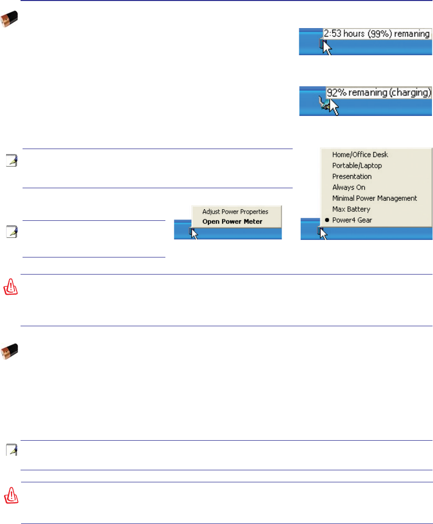
Right-click the battery icon for
sub-menus. Left-click the battery icon for power
management settings.
Note: Screen captures shown here
are examples only and may not re-
ÁHFWZKDW\RXVHHLQ\RXUV\VWHP
Move your mouse over the battery icon
for remaining power information.
When the AC power is connected,
charging status will be shown.
WARNING! Do not leave the battery pack discharged. The battery pack will discharge
over time. If not using a battery pack, it must continued to be charged every three
months to extend recovery capacity or else it may fail to charge in the future.
NOTE: The battery stops charging if the temperature is too high or the battery voltage
is too high.
Checking Battery Power
The battery system implements the Smart Battery standard under
the Windows environment, which allows the battery to accurately
report the amount of charge left in the battery. A fully-charged battery
pack provides the Notebook PC a few hours of working power. But
WKHDFWXDOÀJXUHYDULHVGHSHQGLQJRQKRZ\RXXVHWKHSRZHUVDYLQJ
features, your general work habits, the CPU, system memory size,
and the size of the display panel.
To check the remaining battery power, move your cursor over the
power icon. The power icon is a “battery” when not using AC power
DQGD´SOXJµZKHQXVLQJ$&SRZHU'RXEOHFOLFNRQWKHLFRQIRU
more information and settings.
Charging the Battery Pack
Before you use your Notebook PC on the road, you will have to charge the battery pack. The battery pack
begins to charge as soon as the Notebook PC is connected to external power using the power adapter.
)XOO\FKDUJHWKHEDWWHU\SDFNEHIRUHXVLQJLWIRUWKHÀUVWWLPH$QHZEDWWHU\SDFNPXVWFRPSOHWHO\FKDUJH
before the Notebook PC is disconnected from external power. It takes a few hours to fully charge the
battery when the Notebook PC is turned OFF and may take twice the time when the Notebook PC is
turned ON. The battery charge light turns OFF when the battery pack is charged.
28
3 Getting Started
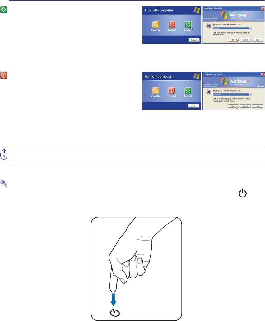
Restarting or Rebooting
After making changes to your operating system,
you may be prompted to restart the system. Some
installation processes will provide a dialog box to
allow restart. To restart the system manually, click
Windows Start button and select Shut Down and
then choose Restart.
Powering OFF
In Windows XP, power OFF the Notebook PC
by clicking Windows Start button and select Shut
Down and then choose Turn off (or Shut down).
For operating systems without proper power man-
agement (DOS, Windows NT), you must close all
applications and exit operating systems and then power OFF by holding the power switch for 2 seconds
(as opposed to 1 second to power ON). Holding the power switch for 2 seconds is necessary in order to
prevent accidental power-OFFs.
IMPORTANT! To protect the hard drive, wait at least 5 seconds after turning OFF your
Notebook PC before turning it back ON.
(Screens are different depending on security settings.)
Emergency Shutdown
In case your operating system cannot properly turn OFF or restart, hold the power button over 4
seconds to shutdown your Notebook PC.
29
Getting Started 3
Special Keyboard Functions
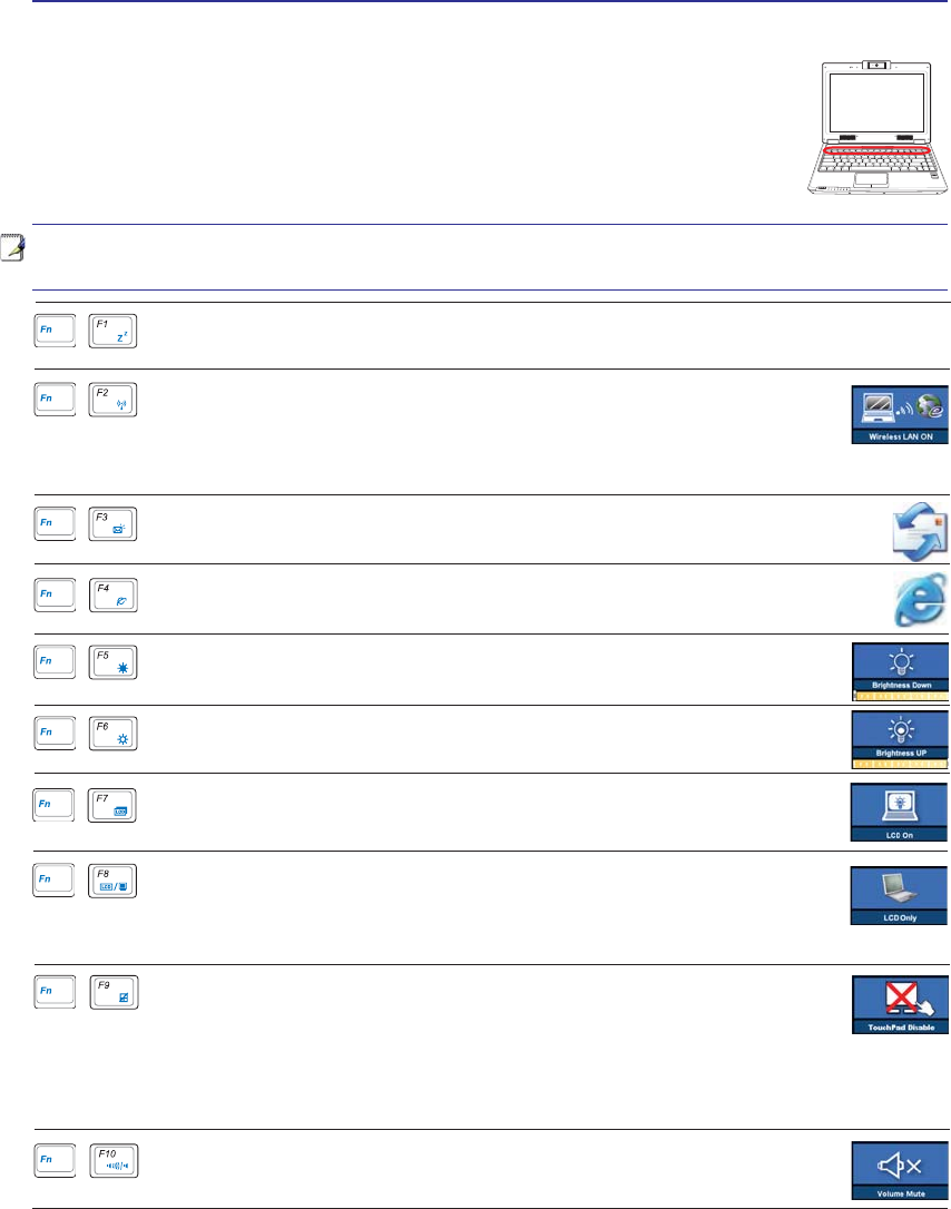
Colored Hot Keys
7KH IROORZLQJ GHÀQHV WKH FRORUHG KRW NH\V RQ WKH 1RWHERRN 3&·V NH\ERDUG 7KH
FRORUHGFRPPDQGVFDQRQO\EHDFFHVVHGE\ÀUVWSUHVVLQJDQGKROGLQJWKHIXQFWLRQ
key while pressing a key with a colored command.
1.3
MEGA
PIXELS
OFF ON
ASUS WIDE SCREEN NOTEBOOK
NOTE: The Hot Key locations on the function keys may vary depending on model but the
functions should remain the same. Follow the icons instead of the function keys.
(continued on next page)
“Zz” Icon (F1): Places the Notebook PC in suspend mode (either Save-to-RAM or Save-
WR'LVNGHSHQGLQJRQVOHHSEXWWRQVHWWLQJLQSRZHUPDQDJHPHQWVHWXS
Radio Tower (F2): Wireless Models Only: Toggles the internal wireless LAN
or Bluetooth (on selected models) ON or OFF with an on-screen-display. When
enabled, the corresponding wireless indicator will light. Windows software
settings are necessary to use the wireless LAN or Bluetooth.
Filled Sun Icon (F5):
'HFUHDVHVWKHGLVSOD\EULJKWQHVV
Open Sun Icon (F6):
Increases the display brightness
Speaker Icons (F10):
Toggles the speakers ON and OFF (only in Windows OS)
Crossed-out Touchpad (F9)7RJJOHVWKHEXLOWLQWRXFKSDG/2&.('GLV-
DEOHGDQG81/2&.('HQDEOHG/RFNLQJWKHWRXFKSDGZLOOSUHYHQW\RX
from accidentally moving the cursor while typing and is best used with an
external pointing device such as a mouse. Note: An indicator between the touchpad buttons
ZLOOOLJKWZKHQWKHWRXFKSDGLV81/2&.('HQDEOHGDQGQRWOLJKWZKHQWKHWRXFKSDG
LV/2&.('GLVDEOHG
“e” Icon (F4): Pressing this button will launch your Internet browser application
while Windows is running.
Envelope Icon (F3): Pressing this button will launch your Email application while
Windows is running.
LCD Icon (F7): Toggles the display panel ON and OFF. (On certain models; stretch-
HVWKHVFUHHQDUHDWRÀOOWKHHQWLUHGLVSOD\ZKHQXVLQJORZUHVROXWLRQPRGHV
LCD/Monitor Icons (F8):7RJJOHVEHWZHHQWKH1RWHERRN3&·V/&'GLVSOD\DQGDQ
H[WHUQDOPRQLWRULQWKLVVHULHV1RWHERRN3&/&'!([WHUQDO0RQLWRU!%RWK7KLV
IXQFWLRQGRHVQRWZRUNLQ&RORUVVHOHFW+LJK&RORULQ'LVSOD\3URSHUW\6HWWLQJV
NOTE: Must connect an external monitor “before” booting up the Notebook PC.
30
3 Getting Started
Colored Hot Keys (Cont.)
1.3
MEGA
PIXELS
OFF ON
ASUS WIDE SCREEN NOTEBOOK
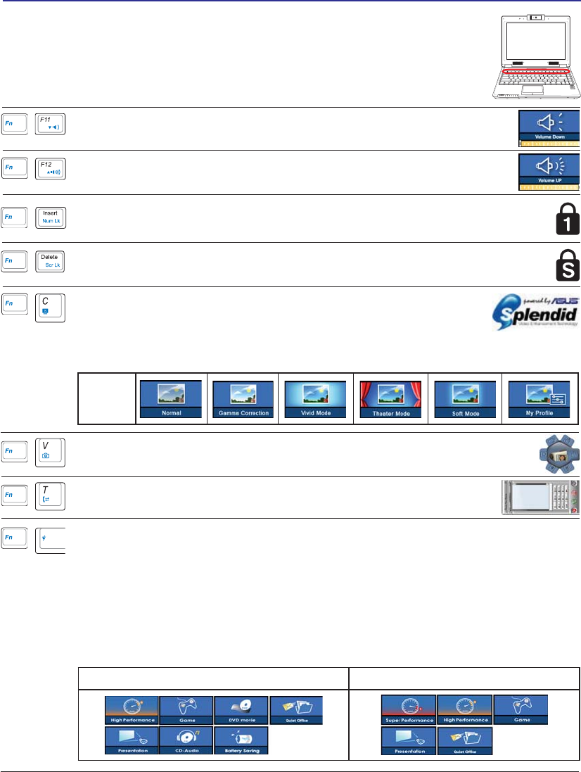
Battery Mode AC Mode
Power4 Gear+ (Fn+Space Bar): The Power4 Gear+ button toggles power savings be-
tween various power saving modes. The power saving modes control many aspects of the
Notebook PC to maximize performance versus battery time.
When you are using an AC power adapter, Power4 Gear+ will switch between modes
in the AC power mode segment. When you remove the AC adapter, Power4 Gear+ will
VZLWFKEHWZHHQPRGHVLQWKHEDWWHU\'&PRGHVHJPHQW:KHQ\RXUHPRYHRUDSSO\WKH
AC adapter, Power4 Gear+ will automatically shift you up or down into the proper mode
VHJPHQW$&RU'&
Speaker Up Icon (F12):
Increases the speaker volume (only in Windows OS)
Speaker Down Icon (F11):
'HFUHDVHVWKHVSHDNHUYROXPHRQO\LQ:LQGRZV26
OSD
Icons
Fn+C: Toggles “Splendid Video Intelligent Technology” function ON
and OFF. This allows switching between different display color enhance-
ment modes in order to improve contrast, brightness, skin tone, and color
saturation for red, green, and blue independently. You can see the current mode through
WKHRQVFUHHQGLVSOD\26'
Fn+V: Toggles “ASUS Life Frame” software application.
Scr Lk (Del): Toggles the “Scroll Lock” ON and OFF. Allows you to use a larger
portion of the keyboard for cell navigation.
Num Lk (Ins): Toggles the numeric keypad (number lock) ON and OFF. Allows you
to use a larger portion of the keyboard for number entering.
Fn+T: Toggles “Power For Phone” software application.
31
Getting Started 3
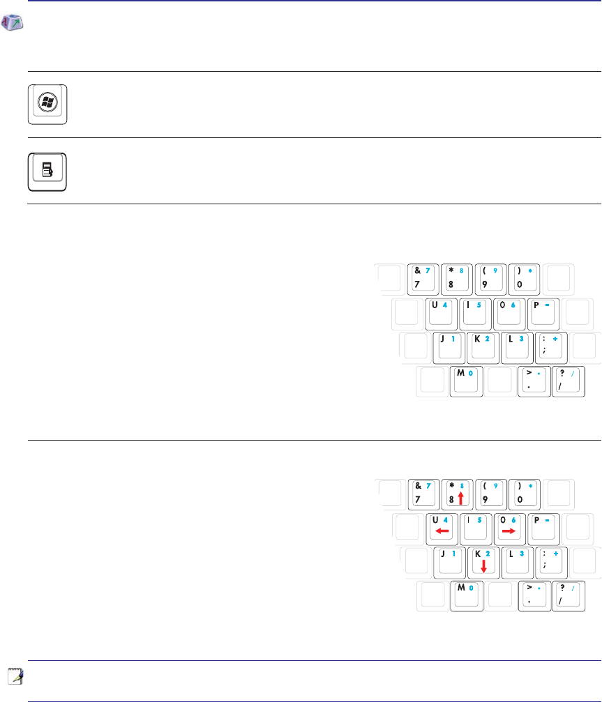
NOTE: The red arrows are illustrated here for your reference. They are not labeled on
the keyboard as shown here.
Microsoft Windows Keys
There are two special Windows keys on the keyboard as described below.
The key with the Windows Logo activates the Start menu located at the bottom left of the Win-
dows desktop.
The other key, that looks like a Windows menu with a small cursor, activates the properties menu
and is equivalent to pressing the right mouse button on a Windows object.
Keyboard as a Numeric Keypad
The numeric keypad is embedded in the keyboard and consists
of 15 keys that make number intensive input more convenient.
These dual-purpose keys are labeled in orange on the key caps.
Numeric assignments are located at the upper right hand corner
RIHDFKNH\DVVKRZQLQWKHÀJXUH:KHQWKHQXPHULFNH\SDGLV
HQJDJHGE\SUHVVLQJ>Fn@>Ins/Num LK@WKHQXPEHUORFN/('OLJKWV
XS,IDQH[WHUQDONH\ERDUGLVFRQQHFWHGSUHVVLQJWKH>Ins/Num LK@
on the external keyboard enables/disables the NumLock on both key-
boards simultaneously. To disable the numeric keypad while keeping
WKHNH\SDGRQDQH[WHUQDONH\ERDUGDFWLYDWHGSUHVVWKH>Fn@>Ins/Num LK@NH\VRQWKH1RWHERRN3&
Keyboard as Cursors
The keyboard can be used as cursors while Number Lock is
ON or OFF in order to increase navigation ease while entering
numeric data in spreadsheets or similar applications.
With Number Lock OFFSUHVV>Fn@DQGRQHRIWKHFXUVRUNH\V
VKRZQ EHORZ )RU H[DPSOH >Fn@>8@ IRU XS >Fn@>.@ IRU GRZQ
>Fn@>U@IRUOHIWDQG>Fn@>O@IRUULJKW
With Number Lock ONXVH>Shift@DQGRQHRIWKHFXUVRUNH\VVKRZQ
EHORZ)RUH[DPSOH>Shift@>8@IRUXS>Shift@>K@IRUGRZQ>Shift@>U@
IRUOHIWDQG>Shift@>O@IRUULJKW
32
3 Getting Started
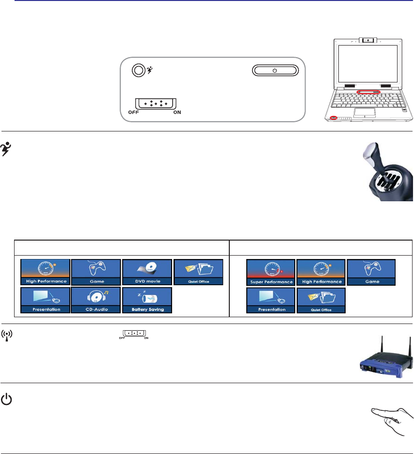
Power Switch
The power switch allows powering ON and OFF the Notebook PC and recovering from
67'8VHWKHVZLWFKRQFHWRWXUQ21DQGRQFHWRWXUQ2))WKH1RWHERRN3&,Q:LQGRZV
XP, this button can also be used to safely turn OFF the Notebook PC. The power switch only
works when the display panel is opened.
Switches
Switches and Status Indicators
1.3
MEGA
PIXELS
OFF ON
ASUS WIDE SCREEN NOTEBOOK
Battery Mode AC Mode
Power4 Gear+ Key
The Power4 Gear+ button toggles power savings between various power saving modes. The
power saving modes control many aspects of the Notebook PC to maximize performance
versus battery time.
When you are using an AC power adapter, Power4 Gear+ will switch between modes in the
AC power mode segment. When you remove the AC adapter, Power4 Gear+ will switch between modes
LQWKHEDWWHU\'&PRGHVHJPHQW:KHQ\RXUHPRYHRUDSSO\WKH$&DGDSWHU3RZHU*HDUZLOODX-
WRPDWLFDOO\VKLIW\RXXSRUGRZQLQWRWKHSURSHUPRGHVHJPHQW$&RU'&
Wireless Switch
Wireless Models Only: Toggles the internal wireless LAN or Bluetooth (on selected models)
ON or OFF with an on-screen display. When enabled, the corresponding wireless indicator
will light. Windows software settings are necessary to use the wireless LAN or Bluetooth.
33
Getting Started 3
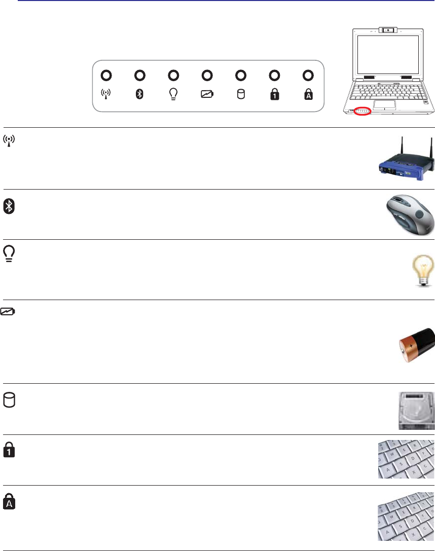
Status Indicators
Front
Battery Charge Indicator
7KHEDWWHU\FKDUJHLQGLFDWRULVDQ/('WKDWVKRZVWKHVWDWXVRIWKHEDWWHU\·VSRZHUDVIROORZV
ON: The Notebook PC’s battery is charging when AC power is connected.
OFF: The Notebook PC’s battery is charged or completely drained.
Blinking: Battery power is less than 10% and the AC power is not connected.
1.3
MEGA
PIXELS
OFF ON
ASUS WIDE SCREEN NOTEBOOK
Wireless Indicator
This is only applicable on models with built-in wireless LAN and/or built-in Bluetooth.
When the built-in wireless LAN and/or built-in Bluetooth is enabled, this indicator will
light. (Windows software settings are necessary.)
Power Indicator
The power indicator lights when the Notebook PC is turned ON and blinks slowly when the Note-
book PC is in the Suspend-to-RAM (Standby) mode. This indicator is OFF when the Notebook
3&LVWXUQHG2))RULQWKH6XVSHQGWR'LVN+LEHUQDWLRQPRGH
Drive Activity Indicator
Indicates that the Notebook PC is accessing one or more storage device(s) such as the hard
GLVN7KHOLJKWÁDVKHVSURSRUWLRQDOWRWKHDFFHVVWLPH
Capital Lock Indicator
,QGLFDWHVWKDWFDSLWDOORFN>&DSV/RFN@LVDFWLYDWHGZKHQOLJKWHG&DSLWDOORFNDOORZVVRPH
of the keyboard letters to type using capitalized letters (e.g. A, B, C). When the capital
lock light is OFF, the typed letters will be in the lower case form (e.g. a,b,c).
Number Lock Indicator
,QGLFDWHVWKDWQXPEHUORFN>1XP/N@LVDFWLYDWHGZKHQOLJKWHG1XPEHUORFNDOORZVVRPH
of the keyboard letters to act as numbers for easier numeric data input.
Bluetooth Indicator
This is only applicable on models with internal Bluetooth (BT). This indicator will light to
show that the Notebook PC’s built-in Bluetooth (BT) function is activated.
34
3 Getting Started
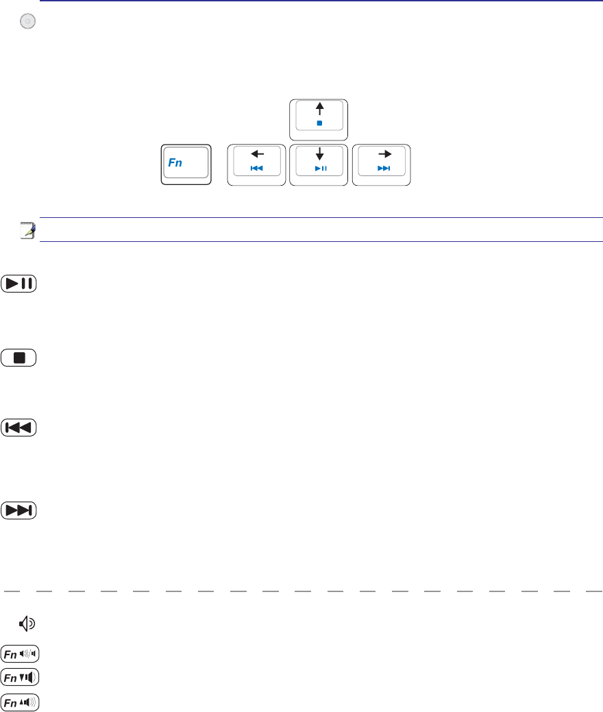
CD Play/Pause
During CD stop, begins CD play.
During CD play, pauses CD play.
CD Stop
During CD stop: Ejects the CD tray.
During CD play: Stops CD play.
CD Skip to Next Track (Fast Forward) & Audio Volume Up
During CD play, this button has two functions:
Track: Push once to skip to the next track during CD playing.
Audio: Hold down to increase audio volume.
Audio Volume Controls
Fn + Speaker Icons (F10): Toggles the audio volume ON and OFF
Fn + Down Speaker Icon (F11): Decreases the audio volume
Fn + Up Speaker Icon (F12): Increases the audio volume
Multimedia Control Keys (on selected models)
The multimedia control keys allows for convenient controlling of the multimedia application. The fol-
ORZLQJGHÀQHVWKHPHDQLQJRIHDFKPXOWLPHGLDFRQWURONH\RQWKH1RWHERRN3&
CD Skip to Previous Track (Rewind) & Audio Volume Down
During CD play, this button has two functions:
Track: 7KHÀUVWSXVKZLOOUHVWDUWWKHFXUUHQWWUDFN6HFRQGSXVKZLOOVNLSWRWKHprevious track.
Audio: Hold down to decrease audio volume.
Use the [Fn] key in combination with the arrow keys for CD control functions.

35
4. Using the Notebook PC
Pointing Device
Storage Devices
Expansion Card
Optical drive
Flash memory card reader
Hard disk drive
Memory (RAM)
Connections
Modem Connection
Network Connection
Wireless LAN Connection (on selected models)
Bluetooth Wireless Connection (on selected models)
Power Management Modes
Fingerprint Scanner (on selected models)
Trusted Platform Module (TPM) (on selected models)
36
4 Using the Notebook PC
IMPORTANT! Do not use any objects in
SODFHRI\RXUÀQJHUWRRSHUDWHWKHWRXFK-
pad or else damage may occur to the
touchpad’s surface.
Pointing Device
The Notebook PC’s integrated touchpad pointing
device is fully compatible with all two/three-but-
ton and scrolling knob PS/2 mice. The touchpad is
pressure sensitive and contains no moving parts;
therefore, mechanical failures can be avoided. A
device driver is still required for working with some
application software.
Using the Touchpad
/LJKWSUHVVXUHZLWKWKHWLSRI\RXUÀQJHULVDOOWKDWLV
required to operate the touchpad. Because the touch-
pad is electrostatic sensitive, objects cannot be used in
SODFHRI\RXUÀQJHUV7KHWRXFKSDG·VSULPDU\IXQFWLRQ
is to move the cursor around or select items displayed
RQWKHVFUHHQZLWKWKHXVHRI\RXUÀQJHUWLSLQVWHDGRI
a standard desktop mouse. The following illustrations
demonstrate proper use of the touchpad.
Moving The Cursor
3ODFH\RXUÀQJHULQWKHFHQWHURIWKHWRXFKSDGDQG
slide in a direction to move the cursor.
6OLGHÀQJHU
forward
6OLGHÀQJHU
left
6OLGHÀQJHU
backward
6OLGHÀQJHU
right
Cursor
Movement
Right Click
Left Click
NOTE: A software-controlled scrolling
function is available after setting up
the included touchpad utility to allow
easy Windows or web navigation.
Scrolling (on selected models)
6OLGH \RXU ÀQJHU XS RU GRZQ RQ WKH ULJKW VLGH WR
scroll a window up or down.
6FUROOLQJRQWKHÀQJHUSULQWVFDQQHU
$IWHU VRIWZDUH VHWXS \RX FDQ XVH WKH ÀQJHUSULQW
scanner as a scroll wheel like that on a mouse.
OFF ON
ASUS WIDE SCREEN NOTEBOOK
37
Using the Notebook PC 4
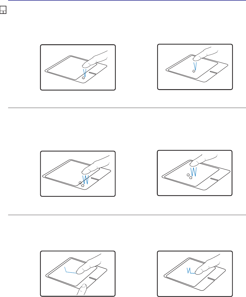
Double-clicking/Double-tapping - This is a common skill for launching a program directly from the
corresponding icon you select. Move the cursor over the icon you wish to execute, press the left button or
tap the pad twice in rapid succession, and the system launches the corresponding program. If the interval
between the clicks or taps is too long, the operation will not be executed. You can set the double-click speed
using the Windows Control Panel “Mouse.” The following 2 examples produce the same results.
Press the left button twice and
release.
Lightly but rapidly strike the
touchpad twice.
Press the left cursor button and
release.
Lightly but rapidly strike the
touchpad.
Clicking/Tapping -:LWKWKHFXUVRURYHUDQLWHPSUHVVWKHOHIWEXWWRQRUXVH\RXUÀQJHUWLSWRWRXFKWKH
WRXFKSDGOLJKWO\NHHSLQJ\RXUÀQJHURQWKHWRXFKSDGXQWLOWKHLWHPLVVHOHFWHG7KHVHOHFWHGLWHPZLOO
change color. The following 2 examples produce the same results.
Clicking Tapping
Double-
Clicking
Double-
Tapping
Touchpad Usage Illustrations
Dragging -'UDJJLQJPHDQVWRSLFNXSDQLWHPDQGSODFHLWDQ\ZKHUHRQWKHVFUHHQ\RXZLVK<RXFDQ
move the cursor over the item you select, and while keeping the left button depressed, moving the cursor
to the desired location, then release the button. Or, you can simply double-tap on the item and hold while
GUDJJLQJWKHLWHPZLWK\RXUÀQJHUWLS7KHIROORZLQJLOOXVWUDWLRQVSURGXFHWKHVDPHUHVXOWV
+ROGOHIWEXWWRQDQGVOLGHÀQJHU
on touchpad.
Lightly strike the touchpad twice,
VOLGLQJÀQJHURQWRXFKSDGGXULQJ
second strike.
Dragging-
Clicking Dragging-
Tapping
38
4 Using the Notebook PC
NOTE: The touchpad responds to movement not to force. There is no need to tap
the surface too hard. Tapping too hard does not increase the responsiveness of the
touchpad. The touchpad responds best to light pressure.
Caring for the Touchpad
The touchpad is pressure sensitive. If not properly cared for, it can be easily damaged. Take note of the
following precautions.
• Make sure the touchpad does not come into contact with dirt, liquids or grease.
'RQRWWRXFKWKHWRXFKSDGLI\RXUÀQJHUVDUHGLUW\RUZHW
'RQRWUHVWKHDY\REMHFWVRQWKHWRXFKSDGRUWKHWRXFKSDGEXWWRQV
'RQRWVFUDWFKWKHWRXFKSDGZLWK\RXUÀQJHUQDLOVRUDQ\KDUGREMHFWV
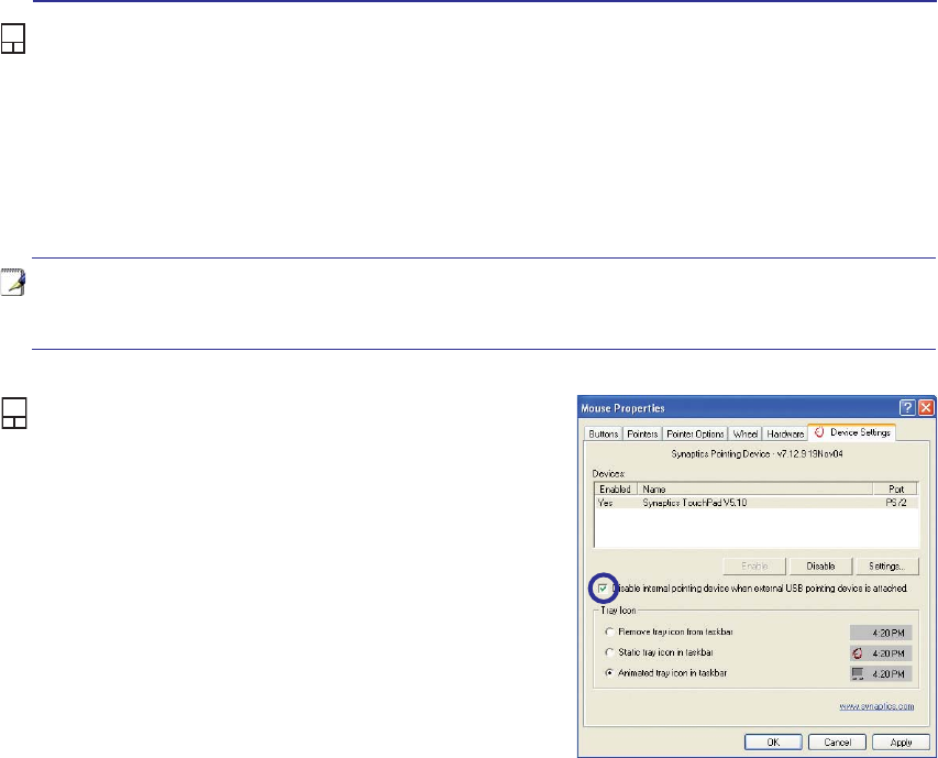
Automatic Touchpad Disabling
(on selected models)
Notebook PC models with newer chipsets will auto-
matically disable the Notebook PC’s touchpad when
an external USB mouse is attached. To turn OFF this
feature, deselect the option in Windows Control
Panel - Mouse Properties - Device Settings.
39
Using the Notebook PC 4
Storage Devices
6WRUDJHGHYLFHVDOORZWKH1RWHERRN3&WRUHDGRUZULWHGRFXPHQWVSLFWXUHVDQGRWKHUÀOHVWRYDULRXV
data storage devices. This Notebook PC has the following storage devices:
• Expansion Card
• Optical drive
• Flash memory reader
• Hard disk drive
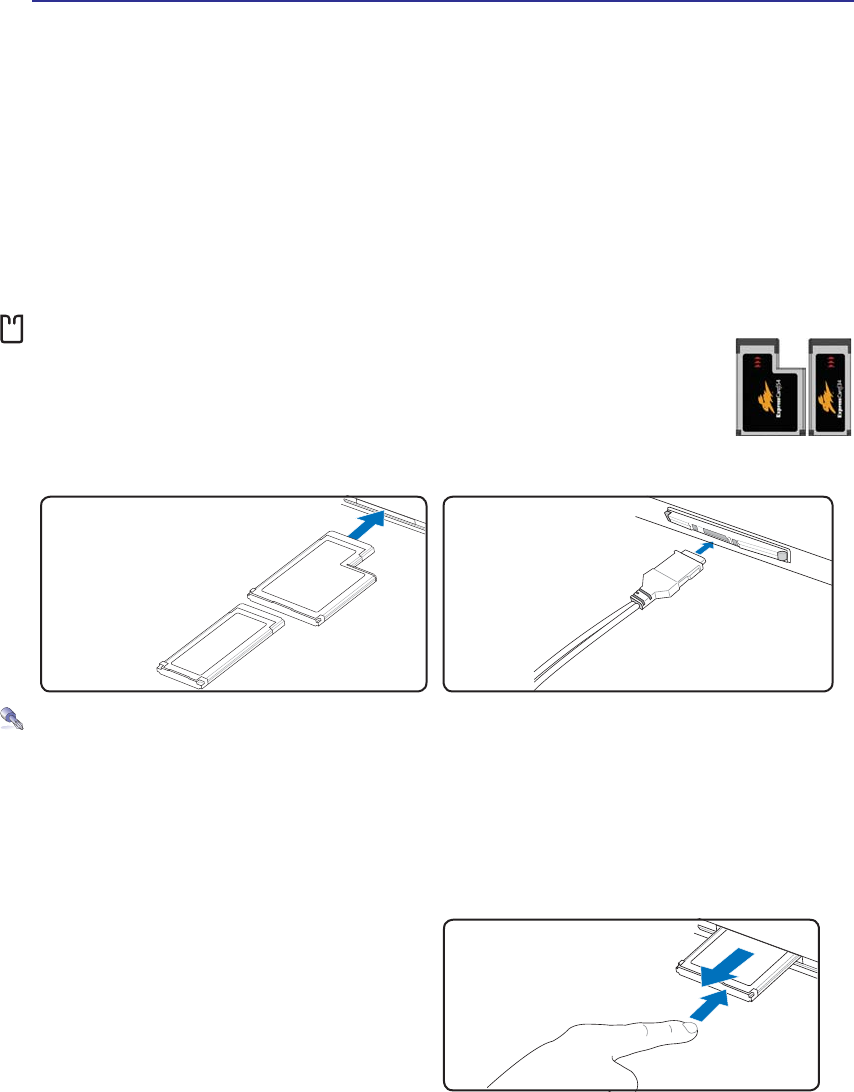
Expansion Card
One 26pin Express card slot is available to support one ExpressCard/34mm or one
ExpressCard/54mm expansion card. This new interface is faster by using a serial bus
supporting USB 2.0 and PCI Express instead of the slower parallel bus used in the PC
card slot. (Not compatible with previous PCMCIA cards.)
Inserting an Expansion Card
Be sure the ExpressCard
is level when inserting.
1. If there is an ExpressCard socket protector,
remove it using the “Removing an Express-
Card” instructions below.
2. Insert the ExpressCard with the connector side
ÀUVWDQGODEHOVLGHXS6WDQGDUG([SUHVV&DUGV
ZLOOEHÁXVKZLWKWKH1RWHERRN3&ZKHQIXOO\
inserted.
3. Carefully connect any cables or adapters
needed by the ExpressCard. Usually connectors
can only be inserted in one orientation. Look
for a sticker, icon, or marking on one side of
the connector representing the top side.
Removing an Expansion Card
The ExpressCard slot does not have an eject but-
ton. Press the ExpressCard inwards and release to
eject the ExpressCard. Carefully pull the ejected
ExpressCard out of the socket.
40
4 Using the Notebook PC
Optical Drive
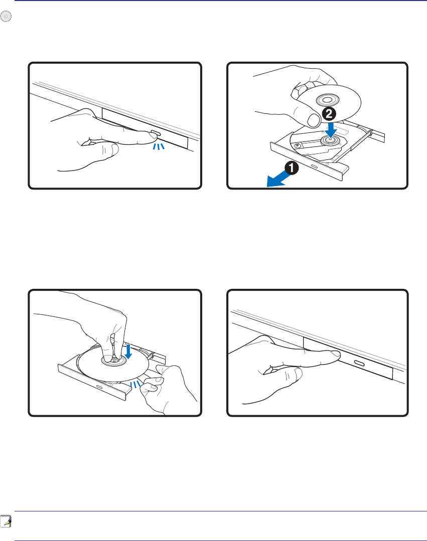
Inserting an optical disc
1. While the Notebook PC’s power is ON, press
the drive’s eject button and the tray will eject
out partially.
2. Gently pull on the drive’s front panel and slide
the tray completely out. Be careful not to touch
WKH&'GULYHOHQVDQGRWKHUPHFKDQLVPV0DNH
sure there are no obstructions that may get
jammed under the drive’s tray.
3. Hold the disc by the edge and face the disc’s
printed side up. Push down on both sides of
the disc’s center until the disc snaps onto the
hub. The hub should be higher than the
disc when correctly mounted.
4. Slowly push the drive’s tray back in. The drive
will begin reading the table of contents (TOC)
on the disc. When the drive stops, the disc is
ready to be used.
NOTE: It is normal to hear as well as feel the CD spinning with great intensity in the
CD drive while data is read.
41
Using the Notebook PC 4
$&'GULYHOHWWHUVKRXOGEHSUHVHQWUHJDUGOHVVRIWKHSUHVHQFHRID&'GLVFLQWKHGULYH$IWHUWKH&'LV
properly inserted, data can be accessed just like with hard disk drives; except that nothing can be written
WRRUFKDQJHGRQWKH&'8VLQJWKHSURSHUVRIWZDUHD&'5:GULYHRU'9'&'5:GULYHFDQDOORZ
&'5:GLVFVWREHXVHGOLNHDKDUGGULYHZLWKZULWLQJGHOHWLQJDQGHGLWLQJFDSDELOLWLHV
9LEUDWLRQLVQRUPDOIRUDOOKLJKVSHHGRSWLFDOGULYHVGXHWRXQEDODQFHG&'VRU&'SULQW7RGHFUHDVH
YLEUDWLRQXVHWKH1RWHERRN3&RQDQHYHQVXUIDFHDQGGRQRWSODFHODEHOVRQWKH&'
Listening to Audio CD
7KHRSWLFDOGULYHVFDQSOD\DXGLR&'VEXWRQO\WKH'9'520GULYHFDQSOD\'9'DXGLR,QVHUWWKH
DXGLR&'DQG:LQGRZVDXWRPDWLFDOO\RSHQVDQDXGLRSOD\HUDQGEHJLQVSOD\LQJ'HSHQGLQJRQWKH
'9'DXGLRGLVFDQGLQVWDOOHGVRIWZDUHLWPD\UHTXLUHWKDW\RXRSHQD'9'SOD\HUWROLVWHQWR'9'
audio. You can adjust the volume using hotkeys or Windows™ speaker icon on the taskbar.
Using the Optical Drive
Optical discs and equipment must be handled with care because of the precise mechanics involved.
.HHSLQPLQGWKHLPSRUWDQWVDIHW\LQVWUXFWLRQVIURP\RXU&'VXSSOLHUV8QOLNHGHVNWRSRSWLFDOGULYHV
WKH1RWHERRN3&XVHVDKXEWRKROGWKH&'LQSODFHUHJDUGOHVVRIWKHDQJOH:KHQLQVHUWLQJD&'LWLV
LPSRUWDQWWKDWWKH&'EHSUHVVHGRQWRWKHFHQWHUKXERUHOVHWKHRSWLFDOGULYHWUD\ZLOOVFUDWFKWKH&'
WARNING! If the CD disc is not properly locked onto the center hub, the CD can be
damaged when the tray is closed. Always watch the CD closely while closing the tray
slowly to prevent damage.
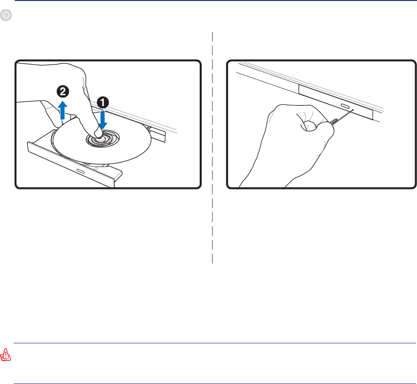
Eject the tray and gently pry the edge of the disc
upwards at an angle to remove the disc from
the hub.
The emergency eject is located in a hole on the op-
tical drive and is used to eject the optical drive tray
LQFDVHWKHHOHFWURQLFHMHFWGRHVQRWZRUN'RQRW
use the emergency eject in place of the electronic
eject. Note: Make sure not to stab the activity
indicator located in the same area.
Actual location will
vary by model.
Optical Drive (Cont.)
Emergency eject
Removing an optical disc
42
4 Using the Notebook PC
IMPORTANT! Never remove cards while or immediately after reading, copying, format-
ting, or deleting data on the card or else data loss may occur.
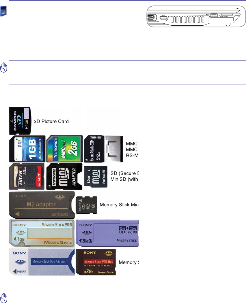
Memory Stick Duo/Pro/Duo Pro/MG (with MS adapater)
Memory Stick (MS)
Memory Stick Magic Gate (MG)
Memory Stick Select
SD (Secure Digital)
MiniSD (with SD adapter)
Memory Stick Micro (with MS adapter)
xD Picture Card
MMC (Multimedia Card)
MMC Plus
RS-MMC (Reduced Size) (with MMC adapter)
Flash Memory Card Reader
Normally a memory card reader must be purchased sepa-
rately in order to use memory cards from devices such as
GLJLWDOFDPHUDV03SOD\HUVPRELOHSKRQHVDQG3'$V7KLV1RWHERRN3&KDVDVLQJOHEXLOWLQPHPRU\
FDUGUHDGHUWKDWFDQXVHPDQ\ÁDVKPHPRU\FDUGVDVVKRZQLQWKHH[DPSOHEHORZ7KHEXLOWLQPHPRU\
card reader is not only convenient, but also faster than most other forms of memory card readers because
it utilizes the internal high-bandwidth PCI bus.
IMPORTANT! Flash memory card compatibility varies depending on Notebook PC model
DQGÁDVKPHPRU\FDUGVSHFLÀFDWLRQV)ODVKPHPRU\FDUGVSHFLÀFDWLRQVFRQVWDQWO\
change so compatibility may change without warning.
Flash Memory Card Examples
43
Using the Notebook PC 4
5
6
3
4
1
2
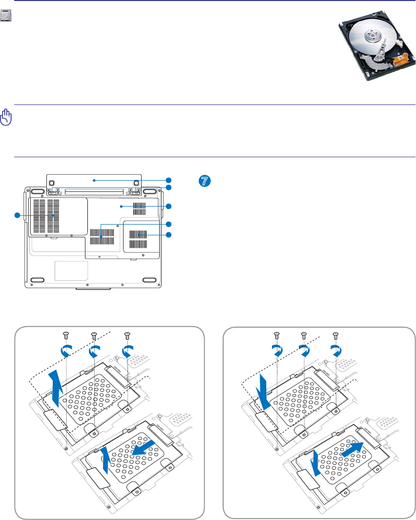
Hard Disk Drive Compartment
The hard disk drive is secured in a compartment. Hard
disk drive upgrades should be done by authorized
service centers or dealers.
7
Removing the Hard Disk Drive Installing the Hard Disk Drive
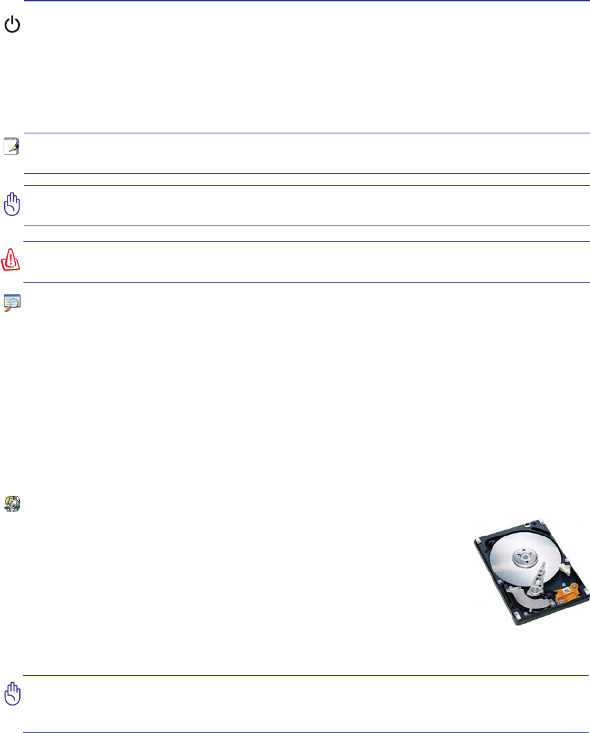
Hard Disk Drive
+DUGGLVNGULYHVKDYHKLJKHUFDSDFLWLHVDQGRSHUDWHDWPXFKIDVWHUVSHHGVWKDQÁRSS\
disk drives and optical drives. The Notebook PC comes with a replaceable 2.5”
(6.35cm) wide and approximately .374” (.95cm) high hard disk drive. Current hard
drives support S.M.A.R.T. (Self Monitoring and Reporting Technology) to detect
hard disk errors or failures before they happen. When replacing or upgrading the
hard drive, always visit an authorized service center or retailer for this Notebook PC.
IMPORTANT! Poor handling of the Notebook PC may damage the hard disk drive.
Handle the Notebook PC gently and keep it away from static electricity and strong
vibrations or impact. The hard disk drive is the most delicate component and will likely
EHWKHÀUVWRURQO\FRPSRQHQWWKDWLVGDPDJHGLIWKH1RWHERRN3&LVGURSSHG
44
4 Using the Notebook PC
Installing a Memory Card Removing a Memory Card
5
6
3
4
1
2
3
Memory (RAM)
Additional memory will increase application performance by decreasing hard
disk access. The BIOS automatically detects the amount of memory in the sys-
WHPDQGFRQÀJXUHV&026DFFRUGLQJO\GXULQJWKH32673RZHU2Q6HOI7HVW
process. There is no hardware or software (including BIOS) setup required after
the memory is installed.
4
The memory compartment provides expansion ca-
pabilities for additional memory. Visit an authorized
service center or retailer for information on memory
upgrades for your Notebook PC. Only purchase
expansion modules from authorized retailers of this
Notebook PC to ensure maximum compatibility and
reliability.
45
Using the Notebook PC 4
NOTE: The built-in modem and network cannot be installed later as an upgrade. After
purchase, modem and/or network can be installed as an expansion card.
CAUTION: For electrical safety concerns, only use telephone cables rated 26AWG or
higher. (see Glossary for more information)
NOTE: When you are connected to an online service, do not place the Notebook PC
in suspend (or sleep mode) or else you will disconnect the modem connection.
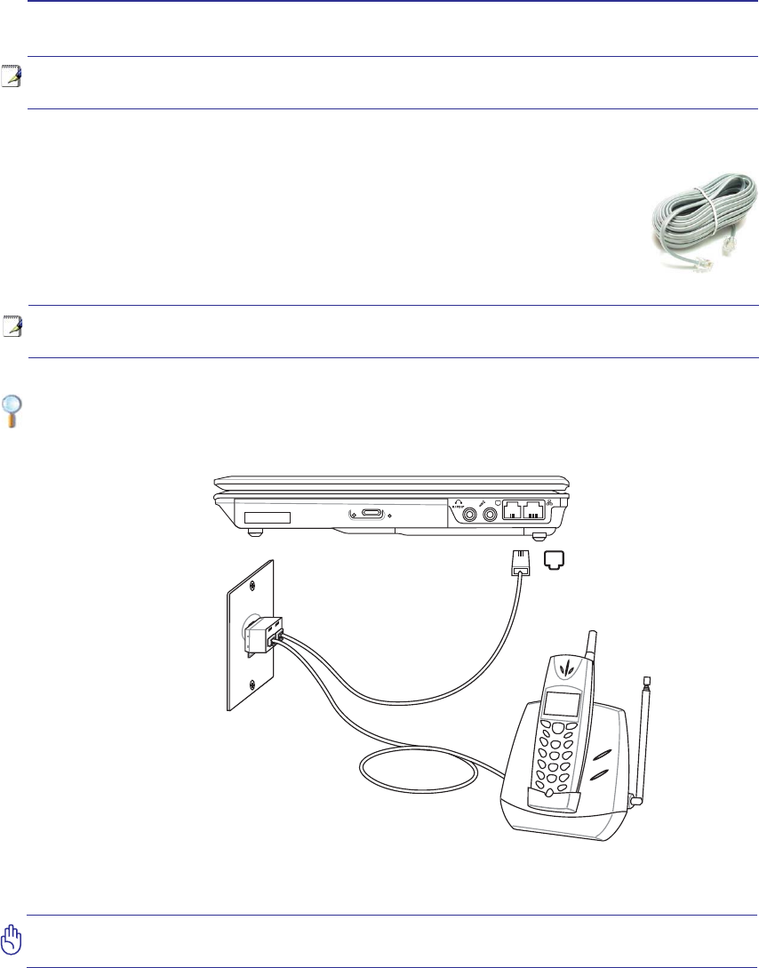
Connections
Example of the Notebook PC connected to a telephone jack for use with the built-in modem:
Modem Connection
The telephone wire used to connect the Notebook PC’s internal modem should have
either two or four wires (only two wires (telephone line #1) is used by the modem) and
should have an RJ-11 connector on both ends. Connect one end to the modem port and
the other end to an analog telephone wall socket (the ones found in residential buildings).
Once the driver is setup, the modem is ready to use.
Telephone Wall
Jack
Telephone cables
with RJ-11 connectors
Telephone
connection is
optional
Telephone connector
is the smaller of the two.
46
4 Using the Notebook PC
WARNING! Only use analog telephone outlets. The built-in modem does not support
the voltage used in digital phone systems. Do not connect the RJ-11 to digital phone
systems found in many commercial buildings or else damage will occur!
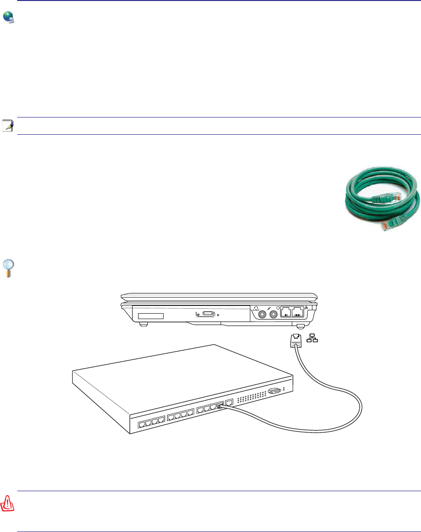
Example of the Notebook PC connected to a Network Hub or Switch for use with the built-in
Ethernet controller.
Network Connection
Connect a network cable, with RJ-45 connectors on each end, to the modem/network port on the Note-
book PC and the other end to a hub or switch. For 100 BASE-TX / 1000 BASE-T speeds, your network
cable must be category 5 or better (not category 3) with twisted-pair wiring. If you plan on running the
interface at 100/1000Mbps, it must be connected to a 100 BASE-TX / 1000 BASE-T hub (not a BASE-T4
KXE)RU%DVH7XVHFDWHJRU\RUWZLVWHGSDLUZLULQJ0ESV)XOO'XSOH[LVVXSSRUWHG
on this Notebook PC but requires connection to a network switching hub with “duplex” enabled. The
software default is to use the fastest setting so no user-intervention is required.
1000BASE-T (or Gigabit) is only supported on selected models.
Twisted-Pair Cable
The cable used to connect the Ethernet card to a host (generally a Hub or Switch)
is called a straight-through Twisted Pair Ethernet (TPE). The end connectors are
called RJ-45 connectors, which are not compatible with RJ-11 telephone connectors.
If connecting two computers together without a hub in between, a crossover LAN
cable is required (Fast-Ethernet model). (Gigabit models support auto-crossover so
a crossover LAN cable is optional.)
Network Hub or Switch
Network cable with RJ-45 connectors
LAN
connector is the
larger of the two.
47
Using the Notebook PC 4
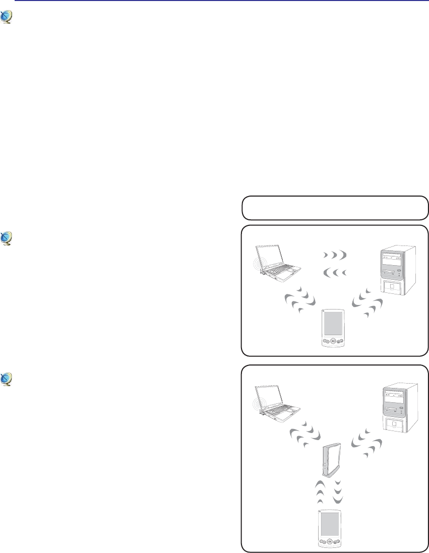
These are examples of the Notebook PC
connected to a Wireless Network.
Desktop PC
PDA
Notebook PC
Access
Point
Desktop PC
PDA
Notebook PC
Wireless LAN Connection (on selected models)
The optional built-in wireless LAN is a compact easy-to-use wireless Ethernet adapter. Implementing
the IEEE 802.11 standard for wireless LAN (WLAN), the optional built-in wireless LAN is capable of
IDVWGDWDWUDQVPLVVLRQUDWHVXVLQJ'LUHFW6HTXHQFH6SUHDG6SHFWUXP'666DQG2UWKRJRQDO)UHTXHQF\
'LYLVLRQ0XOWLSOH[LQJ2)'0WHFKQRORJLHVRQ*+]*+]IUHTXHQFLHV7KHRSWLRQDOEXLOWLQZLUH-
less LAN is backward compatible with the earlier IEEE 802.11 standards allowing seamless interfacing
of wireless LAN standards.
The optional built-in wireless LAN is a client adapter that supports Infrastructure and Ad-hoc modes
JLYLQJ\RXÁH[LELOLW\RQ\RXUH[LVWLQJRUIXWXUHZLUHOHVVQHWZRUNFRQÀJXUDWLRQVIRUGLVWDQFHVXSWR
meters between the client and the access point.
7RSURYLGHHIÀFLHQWVHFXULW\WR\RXUZLUHOHVVFRPPXQLFDWLRQWKHRSWLRQDOEXLOWLQZLUHOHVV/$1FRPHV
with a 64-bit/128-bit Wired Equivalent Privacy (WEP) encryption and Wi-Fi Protected Access (WPA)
features.
Ad-hoc mode
The Ad-hoc mode allows the Notebook PC to connect
to another wireless device. No access point (AP) is
required in this wireless environment.
(All devices must install optional 802.11 wireless LAN adapters.)
Infrastructure mode
The Infrastructure mode allows the Notebook PC and
other wireless devices to join a wireless network cre-
ated by an Access Point (AP) (sold separately) that
provides a central link for wireless clients to commu-
nicate with each other or with a wired network.
(All devices must install optional 802.11 wireless LAN adapters.)
48
4 Using the Notebook PC
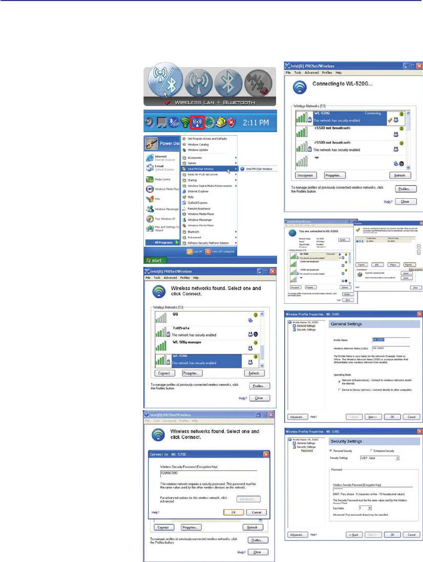
3UHVV >)1 )@ RU GRXEOH FOLFN
the Wireless Console icon on the
taskbar). Four icons will appear
as shown here. Click on the 1st
setting to activate both Wireless
& Bluetooth, or you may select
the 2nd option for Wireless activa-
tion only.
1. Click Start | All Programs |
Intel PROSet Wireless | Intel
PROSet Wireless.
2. Select the Network by double
clicking or click on connect.
(Eg: WL-520G network)
3. If the network has a security
setup, a window will appear
requesting a password to con-
nect.
4. After connecting, it will indi-
cate that “You are connected to
(network)” and showing the IP
address.
Trouble Shooting
&KDQJLQJQHWZRUNSURÀOHSDVV-
word
1. Select the Network then click
3URÀOH and click Properties.
3URÀOHQDPHZLOOQRWQHHGWR
be changed. For “Operating
Mode” select Infrastructure
mode.
3. Select Personal Security and
re-enter the password then
click Ok.
Intel PROSet (3945) Wireless LAN (on selected models)
Connecting to a network
49
Using the Notebook PC 4
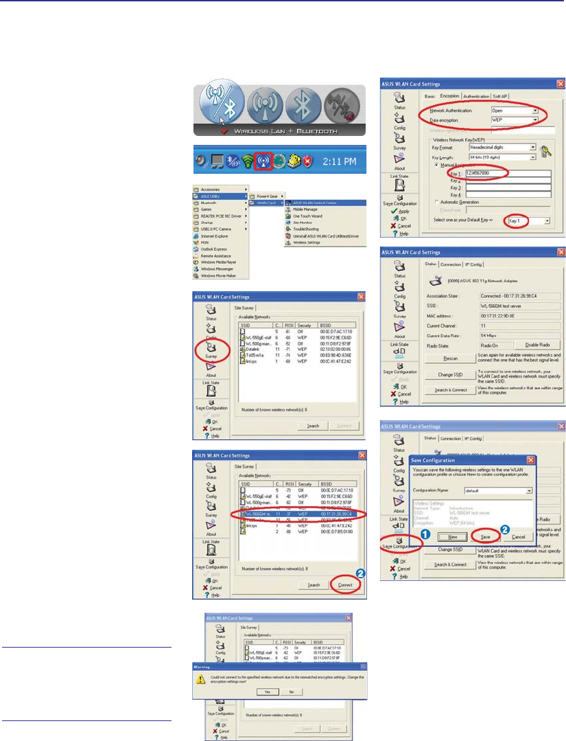
3UHVV>)1)@RUGRXEOHFOLFN
the Wireless Console icon on
the taskbar). Four icons will
appear as shown here. Click on
the 1st setting to activate both
Wireless & Bluetooth, or you
may select the 2nd option for
Wireless activation only.
1. Click Start | Programs
| ASUS Utility | WLAN
Card | ASUS WLAN Con-
trol Center.
2. On the left hand side menu,
click Survey to start scan-
ning for available networks
in your area.
3. The list will show all avail-
able networks within your
area. Select the network you
want and click Connect.
4. If the selected Network has
security settings, you may
be required to enter a pass-
word.
5. Click the Encryption tab
to configure the Network
Authentication mode and
Password.
6. The Status tab will show
connection status and de-
tails.
Note: Click “Save Con-
ÀJXUDWLRQµ DQG ´6DYHµ
to remember settings
for this network.
ASUS Wireless LAN (on selected models)
Connecting to a network
50
4 Using the Notebook PC
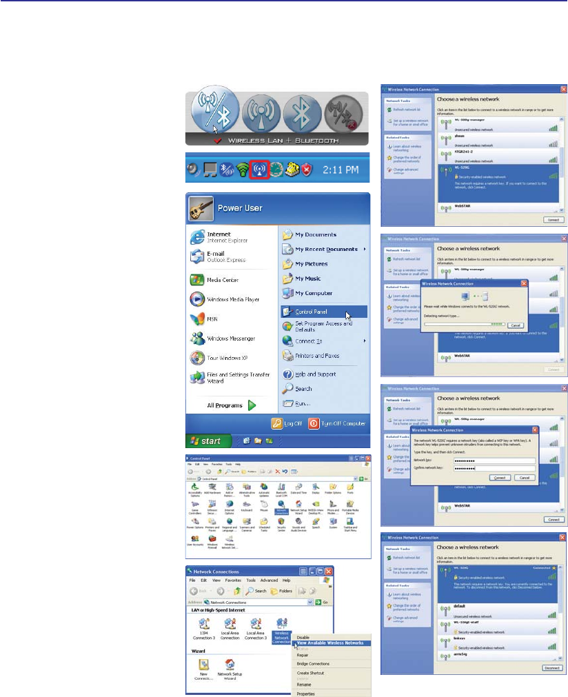
3UHVV >)1 )@ RU GRXEOH FOLFN
the Wireless Console icon on the
taskbar). Four icons will appear
as shown here. Click on the 1st
setting to activate both Wireless
& Bluetooth, or you may select
the 2nd option for Wireless acti-
vation only.
1. Click on Start and select
Control Panel
2. Click on the icon Network
Connections (If this icon
cannot be seen, click “Switch
to Classic View” on the left
side menu.
3. Right click on the icon Wire-
less Network Connection
and select View Available
Wireless Networks.
4. Select Refresh network list
from the left side menu and
a list of available network
within your area and its sig-
nal strength will show. Select
your network and click on
Connect.
'HWHFWLQJ DQG FRQQHFWLQJ
will start to initiate as shown
here.
6. When connecting, you may
have to enter a password.
7. After connection has been
established, “Connected”
will be shown on the right
side above the signal strength
indicator.
Windows Wireless Network Connection
Connecting to a network
51
Using the Notebook PC 4
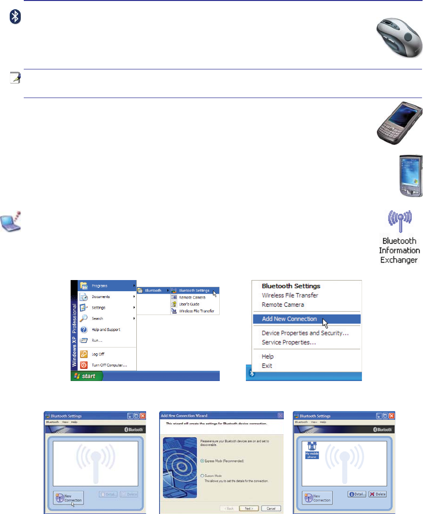
Add New Connection from the
Bluetooth taskbar icon
Bluetooth Settings from Windows Start |
Programs | Bluetooth
Click New Connection from
Bluetooth Settings. Follow the wizard to add Bluetooth
devices. After complete, you should see
your device in the window.
Pairing with Bluetooth-enabled devices
<RXÀUVWQHHGWRSDLU\RXU1RWHERRN3&ZLWKD%OXHWRRWKHQDEOHGGHYLFHEHIRUH\RXFDQ
connect to it. Make sure the Bluetooth-enabled device is turned ON and ready to accept a
pair. Launch Bluetooth Settings from Windows Start | Programs | Bluetooth or select
Add New Connection from the Bluetooth taskbar icon if available.
Bluetooth Wireless Connection (on selected models)
Notebook PCs with Bluetooth technology eliminates the need for cables for connecting
Bluetooth-enabled devices. Examples of Bluetooth-enabled devices may be Notebook PCs,
'HVNWRS3&VPRELOHSKRQHVDQG3'$V
Note: If your Notebook PC did not come with built-in Bluetooth, you need to connect
a USB or ExpressCard Bluetooth module in order to use Bluetooth.
Bluetooth-enabled mobile phones
<RXFDQZLUHOHVVFRQQHFWWR\RXUPRELOHSKRQH'HSHQGLQJRQ\RXUPRELOHSKRQH·VFDSD-
ELOLWLHV\RXFDQWUDQVIHUSKRQHERRNGDWDSKRWRVVRXQGÀOHVHWFRUXVHLWDVDPRGHPWR
connect to the Internet. You may also use it for SMS messaging.
Bluetooth-enabled computers or PDAs
<RXFDQZLUHOHVVFRQQHFWWRDQRWKHUFRPSXWHURU3'$DQGH[FKDQJHÀOHVVKDUHSHULSKHUDOVRU
share Internet or network connections. You may also make use of Bluetooth-enabled wireless
keyboard or mouse.

52
4 Using the Notebook PC
Power Management Modes
The Notebook PC has a number of automatic or adjustable power saving features that you can use to
maximize battery life and lower Total Cost of Ownership (TCO). You can control some of these features
through the Power menu in the BIOS Setup. ACPI power management settings are made through the
operating system. The power management features are designed to save as much electricity as possible
by putting components into a low power consumption mode as often as possible but also allow full
operation on demand. These low power modes are referred to as “Stand by” (or Suspend-to-RAM) and
´+LEHUQDWLRQµPRGHRU6XVSHQGWR'LVN67'7KH6WDQGE\PRGHLVDVLPSOHIXQFWLRQSURYLGHGE\WKH
operating system. When the Notebook PC is in either one of the power saving modes, the status will be
VKRZQE\WKHIROORZLQJ´6WDQGE\µ3RZHU/('%OLQNVDQG´+LEHUQDWLRQµ3RZHU/('2))
Full Power Mode & Maximum Performance
The Notebook PC operates in Full Power mode when the power management function is disabled by
FRQÀJXULQJ:LQGRZVSRZHUPDQDJHPHQWDQG6SHHG6WHS:KHQWKH1RWHERRN3&LVRSHUDWLQJLQ)XOO
3RZHU0RGHWKH3RZHU/('UHPDLQV21,I\RXDUHFRQVFLRXVRIERWKV\VWHPSHUIRUPDQFHDQGSRZHU
consumption, select “Maximum Performance” instead of disabling all power management features.
ACPI
$GYDQFHG&RQÀJXUDWLRQDQG3RZHU0DQDJHPHQW$&3,ZDVGHYHORSHGE\,QWHO0LFURVRIWDQG7RVKLED
especially for Windows and later to control power management and Plug and Play features. ACPI is the
new standard in power management for Notebook PCs.
NOTE: APM was used in older operating systems like Windows NT4 and Windows 98.
Because newer operating systems like Windows XP, Windows 2000, and Windows ME
utilize ACPI, APM is no longer fully supported on this Notebook PC.
Suspend Mode
,Q´6WDQGE\µ675DQG´+LEHUQDWLRQµ67'WKH&38FORFNLVVWRSSHGDQGPRVWRIWKH1RWHERRN3&
devices are put in their lowest active state. The suspend mode is the lowest power state of the Notebook
3&7KH1RWHERRN3&HQWHUVVXVSHQGPRGHZKHQWKHV\VWHPUHPDLQVLGOHIRUDVSHFLÀHGDPRXQWRIWLPH
RUPDQXDOO\XVLQJWKH>)Q@>)@NH\V7KH3RZHU/('EOLQNVZKHQWKH1RWHERRN3&LVLQ675PRGH
,Q67'PRGHWKH1RWHERRN3&ZLOODSSHDUWREHSRZHUHG2))5HFRYHUIURP675E\SUHVVLQJDQ\
NH\ERDUGEXWWRQH[FHSW)Q5HFRYHUIURP67'E\XVLQJWKHSRZHUVZLWFKMXVWOLNHSRZHULQJ21WKH
Notebook PC).
Power Savings
,QDGGLWLRQWRUHGXFLQJWKH&38FORFNWKLVPRGHSXWVGHYLFHVLQFOXGLQJWKH/&'EDFNOLJKWLQWKHLUORZHU
active state. The Notebook PC enters “Stand by” mode (low priority) when the system remains idle for a
VSHFLÀHGDPRXQWRIWLPH7KHWLPHRXWFDQEHVHWWKURXJK:LQGRZVSRZHUPDQDJHPHQWKLJKHUSULRULW\
To resume system operation, press any key.

53
Using the Notebook PC 4
Thermal Power Control
There are three power control methods for controlling the Notebook PC’s thermal state. These power
FRQWUROFDQQRWEHFRQÀJXUHGE\WKHXVHUDQGVKRXOGEHNQRZQLQFDVHWKH1RWHERRN3&VKRXOGHQWHU
these states. The following temperatures represent the chassis temperature (not CPU).
• The fan turns ON for active cooling when the temperature reaches the safe upper limit.
• The CPU decreases speed for passive cooling when the temperature exceeds the safe upper limit.
• The system shut down for critical cooling when temperature exceeds the maximum safe upper
limit.
Power State Summary
STATE ENTRY EVENT EXIT EVENT
“Stand by” • “Stand by” through Windows Start button
• Timer as set though “Power Management” in
Windows Control Panel (higher priority)
• Any device
• Battery low
STR (“Stand by”)
(Suspend-to-RAM) • Hotkey (see “Colored Hotkeys” under “Special
Keyboard Functions” in the previous section) • Signal from modem port
• Power button or any key
STD (“Hibernate”)
(Suspend-to-Disk) • Hotkey (see “Colored Hotkeys” under “Special
Keyboard Functions” in the previous section) • Power button
Soft OFF 3RZHUEXWWRQFDQEHGHÀQHGDV675RU67'
• “Shut down” through Windows Start button • Power button
54
4 Using the Notebook PC
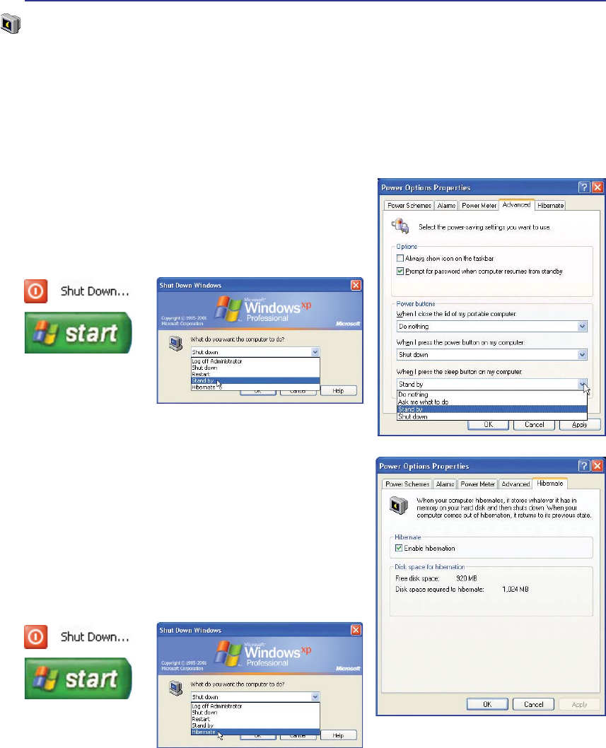
“Stand by” is the same as Suspend-to-RAM (STR). This
function stores your current data and status in RAM while
many components are turned OFF. Because RAM is volatile,
it requires power to keep (refresh) the data. To operate: select
“Start” | “Shut down”, and “Stand by”.
“Hibernate” LV WKH VDPH DV 6XVSHQGWR'LVN 67' DQG
stores your current data and status on the hard disk drive. By
doing this, RAM does not have to be periodically refreshed
and power consumption is greatly reduced but not completely
eliminated because certain wake-up components like LAN
needs to remain powered. “Hibernate” saves more power
compared to “Stand by”. To operate: Enable hibernation
in “Power Options” and select “Start” | “Shut down”, and
“Hibernate”.
Stand by and Hibernate
Power management settings can be found in the Windows control panel. The following shows the power
RSWLRQVSURSHUWLHVLQ:LQGRZV<RXFDQGHÀQH´6WDQG%\µRU´6KXWGRZQµIRUFORVLQJWKHGLVSOD\SDQHO
pressing the power button, or activating sleep mode. “Stand by” and “Hibernate” saves power when
your Notebook PC is not in use by turning OFF certain components. When you resume your work, your
last status (such as a document scrolled down half way or email typed half way) will reappear as if you
never left. “Shut down” will close all applications and ask if you want to save your work if any are not
saved.
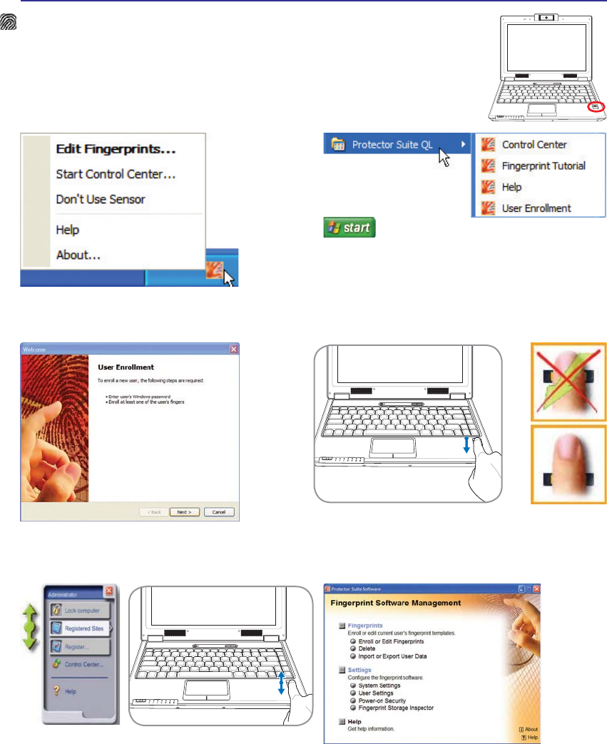
55
Using the Notebook PC 4
OFF ON
ASUS WIDE SCREEN NOTEBOOK
Fingerprint Scanner (on selected models)
7KHÀQJHUSULQWVFDQQHUFDQEHXVHGIRULQVWDQWDQGVHFXUHXVHUDXWKHQWLFDWLRQ
1.3
MEGA
PIXELS
OFF ON
ASUS WIDE SCREEN NOTEBOOK
/HIWRUULJKWFOLFNWKHÀQJHUSULQWWDVNEDULFRQ
WRRSHQWKHPHQXWRHGLWÀQJHUSULQWVRUPDNH
control settings.
,I\RXKDYHQRWFRQÀJXUHGDXVHU\RXZLOOEH
directed to the “User Enrollment”. Follow the
LQVWUXFWLRQVWRVHWXSWKHÀQJHUSULQWVFDQQHU
6FDQQLQJ\RXUÀQJHUSULQWUHTXLUHVWKDW\RXUÀQJHUEHVWUDLJKW
DQGÁDWDVVKRZQKHUH
After you setup a user, you can open the
Control Center to edit Fingerprints or make
software settings.
You can launch the Control Center from Windows “Start” if
the taskbar icon is not running.
After software setup, you can use the
ÀQJHUSULQWVFDQQHUDVDVFUROOZKHHOOLNHWKDW
on a mouse.
OFF ON
ASUS WIDE SCREEN NOTEBOOK
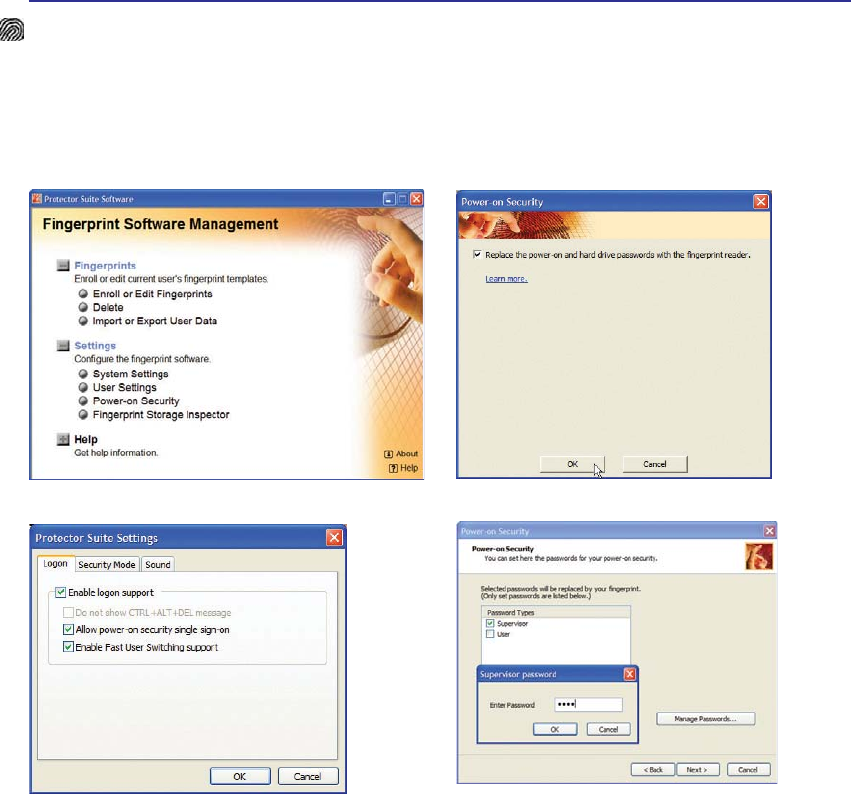
56
4 Using the Notebook PC
Fingerprint Login
7KHÀQJHUSULQWVFDQQHUFDQEHXVHGWRUHSODFHWKHV\VWHPERRWXSDQGRU:LQGRZVORJLQSDVVZRUGFKHFN
To use this feature:
1. You must set a Supervisor Password on the “Security” page in BIOS SETUP UTILITY.
2. Password CheckRQWKH´6HFXULW\µSDJHLQ%,266(78387,/,7<PXVWEHVHWWR>)LQJHUSULQW@
3. Choose Power-on Security in the “Control Center”. 4. Select “Replace the power-on and hard...”.
5. Select “Allow power-on security single
VLJQRQµ in System Settings from the “Control
Center”. This page allows you to select
ÀQJHUSULQWORJRQRSWLRQV
'XULQJV\VWHPERRW\RXZLOOVHH´6ZLSHÀQJHUWRDXWKRUL]HDFFHVVµ,I\RXGRQRWVXFFHVVIXOO\
GRVRLQWKHDOORZHGWLPHLWZLOOUHYHUWWR´(QWHU3DVVZRUGBµ3UHVVLQJWKH>(6&@NH\ZLOOVKRZ
´%LRPHWULFRSHUDWLRQFDQFHOOHGµDQGDOORZ\RXWRHQWHUDSDVVZRUGLQVWHDGRIXVLQJDÀQJHUSULQW,Q
HLWKHUFDVH\RXZLOOVHH$&&(66*5$17('ZKHQDXWKRUL]HG
,I\RXXVHGDÀQJHUSULQWRQV\VWHPERRW\RXZLOODOVRDXWRPDWLFDOO\ORJLQWR:LQGRZVZLWK\RXU
account. You will see “Succeeded” on the login screen. If you used a password on system boot, you
ZLOOEHUHTXLUHGWRXVH\RXUÀQJHUSULQWRUW\SHLQDSDVVZRUGWRORJLQWR:LQGRZV
6. Set the password type for power-on security
DVVRFLDWHGZLWK\RXUÀQJHUSULQWLQ´(QUROORU(GLW
Fingerprints” from the “Control Center”. You will
be asked for the relevant BIOS password based
on your selection.
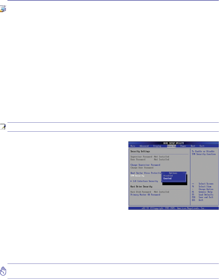
57
Using the Notebook PC 4
Trusted Platform Module (TPM) (on selected models)
The TPM, or Trusted Platform Module, is a security hardware device on the system board that will hold
computer-generated keys for encryption. It is a hardware-based solution that an help avoid attacks by
hackers looking to capture passwords and encryption keys to sensitive data. The TPM provides the abil-
ity to the PC or notebook to run applications more secure and to make transactions and communication
more trustworthy.
The security features provided by the TPM are internally supported by the following cryptographic capa-
bilities of each TPM: hashing, random number generation, asymmetric key generation, and asymmetric
encryption/decryption. Each individual TPM on each individual computer system has a unique signature
initialized during the silicon manufacturing process that further enhances its trust/security effectiveness.
Each individual TPM must have an Owner before it is useful as a security device.
TPM Applications
TPM is useful for any customer that is interested in providing an addition layer of security to the com-
puter system. The TPM, when bundled with an optional security software package, can provide overall
V\VWHP VHFXULW\ ÀOH SURWHFWLRQ FDSDELOLWLHV DQG SURWHFW DJDLQVW HPDLOSULYDF\ FRQFHUQV 730 KHOSV
provide security that can be stronger than that contained in the system BIOS, operating system, or any
non-TPM application.
Enabling TPM Security
Enter BIOS SetupSUHVV>)@RQV\VWHPVWDUWXS
On Security page, set TPM Security to [Enabled]
,PSRUWDQW8VH\RXU730DSSOLFDWLRQҋV´5HVWRUHµRU´0LJUDWLRQµIXQFWLRQWREDFNXS
your TPM security data.
Note: The TPM is disabled by default. Use BIOS setup to enable it.
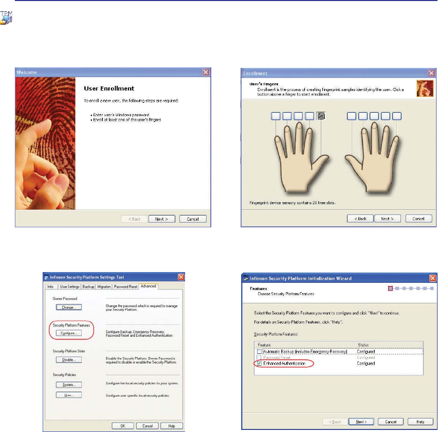
58
4 Using the Notebook PC
,QLWLDOL]H,QÀQHRQ7306HFXULW\3ODWIRUP (QUROOÀQJHUSULQWXVLQJ364/
6HWWLQJ,QÀQHRQ6HFXULW\3ODWIRUP&OLFN&RQ-
ÀJXUHRQWKH´$GYDQFHGµSDJH
4. Check Enhanced Authentication and click
Next.
TPM Setup for Fingerprint Scanner
7KHVHLQVWUXFWLRQVZLOOVKRZ\RXKRZWRXVHWKHÀQJHUSULQWVFDQQHUWRDXWKHQWLFDWHWKH,QÀQHRQ730
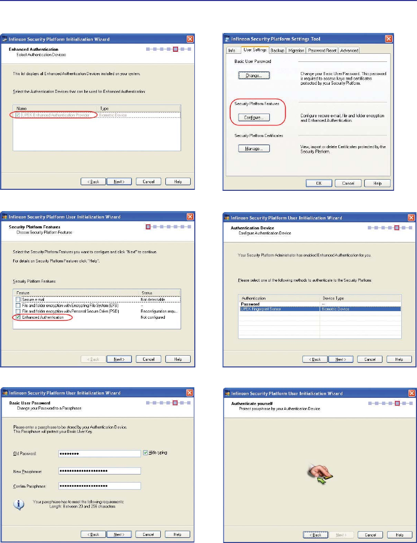
59
Using the Notebook PC 4
5. Choose UPEK Enhanced Authentication Provider. &OLFN&RQÀJXUHLQ8VHU6HWWLQJVSDJH
7. Check the Enhanced Authentication and Next. 8. Select the UPEK Fingerprint Sensor and Next.
9. Enter the old password and a new passphrase. 6ZLSHÀQJHUWRDXWKHQWLFDWH
TPM Setup for Fingerprint Scanner (Cont.)
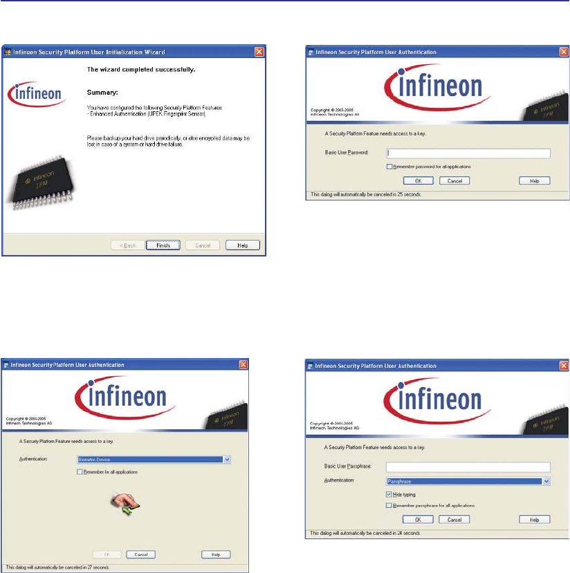
60
4 Using the Notebook PC
11. Settings are complete. Authentication when
accessing TPM in Infineon Security Platform
will change from asking TPM basic password to
Biometric device (Fingerprint Reader) or new
passphrase.
12. This is the original screen before setting en-
hanced authentication.
13. This is the screen after setting enhanced au-
thentication.
14. This is the screen after setting enhanced authen-
WLFDWLRQLIÀQJHUSULQWQRWVXFFHVVIXOLQWKHDOORZHG
time (previous screen).
TPM Setup for Fingerprint Scanner (Cont.)
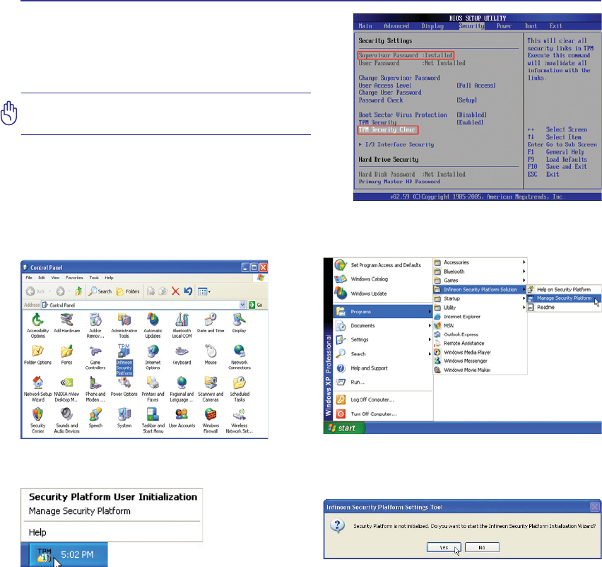
61
Using the Notebook PC 4
You can launch the Security Platform
application from Windows “Control Panel”.
You can launch the Security Platform
application from Windows “Start” menu.
When the Security Platform is running, this
icon will show in the Windows taskbar. You
can choose to initialize or manage here.
When you launch the Security Platform
DSSOLFDWLRQIRUWKHÀUVWWLPHDQVZHUYes and
IROORZWKHLQVWUXFWLRQVWRFRQÀJXUHLW
Clearing TPM Secured Data
When Supervisor Password is installed, TPM Se-
curity Clear will appear. Use this item to clear all
data secured by TPM.
Important: Use should routinely backup
your TPM secured data.
Running Security Platform in Windows

62
4 Using the Notebook PC

Appendix
Optional Accessories & Connections
Operating System and Software
System BIOS Settings
Common Problems and Solutions
Windows Software Recovery
NTFS Converter
Glossary
Declarations and Safety Statements
Notebook PC Information
NOTE: Photos and icons in this manual are used for artistic purposes only and do not
show what is actually used in the product itself.

A Appendix
Optional Accessories
These items, if desired, come as optional items to complement your Notebook PC.
USB Flash Memory Disk
$86%ÁDVKPHPRU\GLVNLVDQRSWLRQDOLWHPWKDWFDQUHSODFHWKH0%ÁRSS\
disk and provide storage up to several hundred megabytes, higher transfer speeds,
and greater durability. When used in current operating systems, no drivers are
necessary.
USB Hub (Optional)
Attaching an optional USB hub will increase your USB ports and allow you to
quickly connect or disconnect many USB peripherals through a single cable.
Vehicle Power Adapter
The vehicle power adapter provides a source of power for using the Notebook
PC and/or charging the Notebook PC’s battery pack while in transit when no AC
power is available. This product is an essential tool for today’s mobile profes-
sional. Your purchase will enhance the power, performance, and versatility of
your portable computer while traveling on the road or on the sea. The Vehicle
Power Adapter can be used in vehicles or boats using a standard cigarette lighter
VRFNHW7KH9HKLFOH3RZHU$GDSWHUDFFHSWVLQSXWUDQJHVIURP9'&9ROWV
'LUHFW&XUUHQWWR9'&DQGSURYLGHV9'&XSWR::DWWV
USB Floppy Disk Drive
$QRSWLRQDO86%LQWHUIDFHÁRSS\GLVNGULYHFDQDFFHSWDVWDQGDUG0%RU
.%LQFKÁRSS\GLVNHWWH
WARNING! To prevent system failures, use (Windows XP Safely
Remove Hardware) on the taskbar before disconnecting the USB
ÁRSS\GLVNGULYH(MHFWWKHÁRSS\GLVNEHIRUHWUDQVSRUWLQJWKH
Notebook PC to prevent damage from shock.
Windows Vista
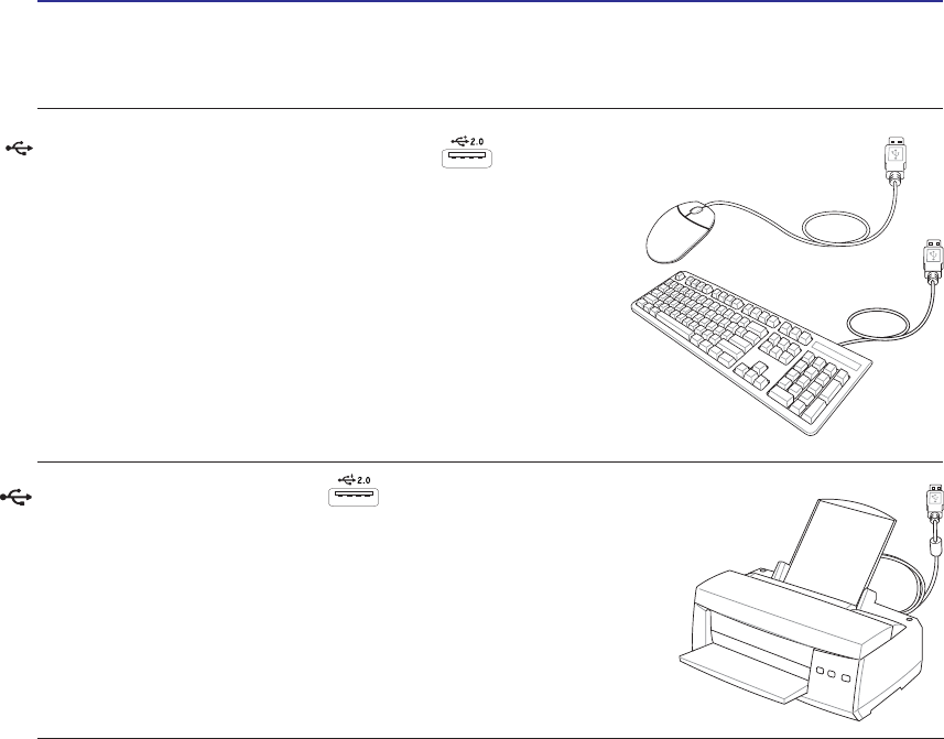
Appendix A
Optional Connections
These items, if desired, may be purchased from third-parties.
USB Keyboard and Mouse
Attaching an external USB keyboard will allow data entry to be
more comfortable. Attaching an external USB mouse will allow
Windows navigation to be more comfortable. Both the external
USB keyboard and mouse will work simultaneously with the
Notebook PC’s built-in keyboard and touchpad.
Printer Connection
One or more USB printers can be simultaneously used on any USB port
or USB hub.