ASUSTeK Computer MWOM4LA MOTHERBOARD User Manual FRONT A8V E Deluxe P65
ASUSTeK Computer Inc MOTHERBOARD FRONT A8V E Deluxe P65
UserManual.wiki
>
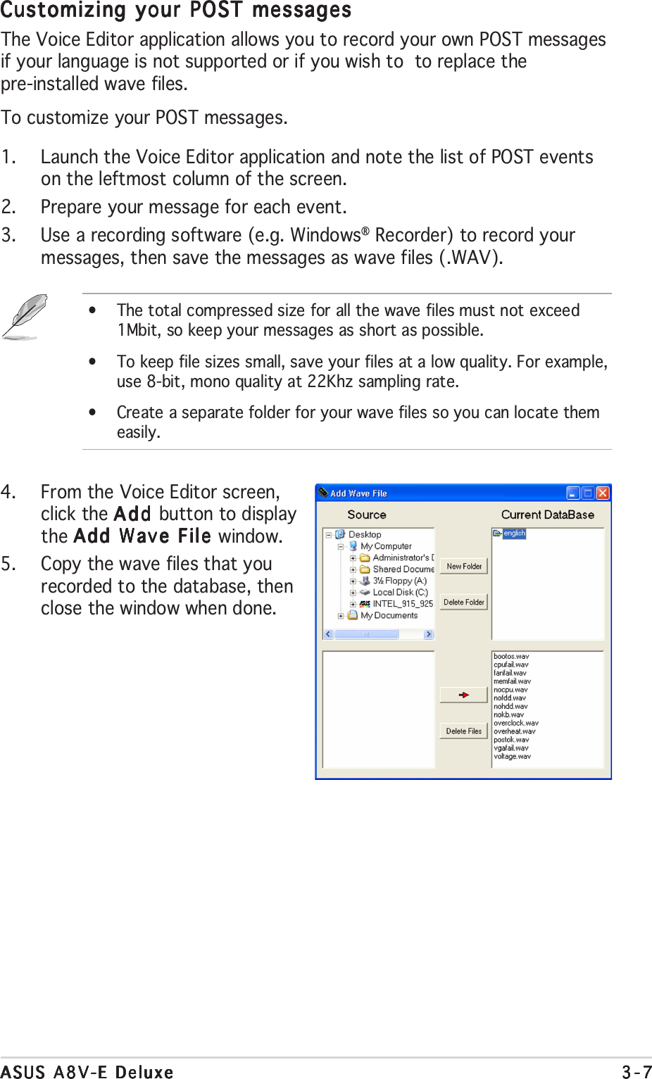
ASUSTeK Computer
>
MWOM4LA User Manual
>
USERS MANUAL 1
Contents
1.
users manual
2.
USERS MANUAL 1
3.
USERS MANUAL 2
USERS MANUAL 1
Navigation menu
Upload a User Manual
Namespaces
Wiki Guide
HTML
PDF
Info
Views
User Manual
Discussion / Help
Navigation
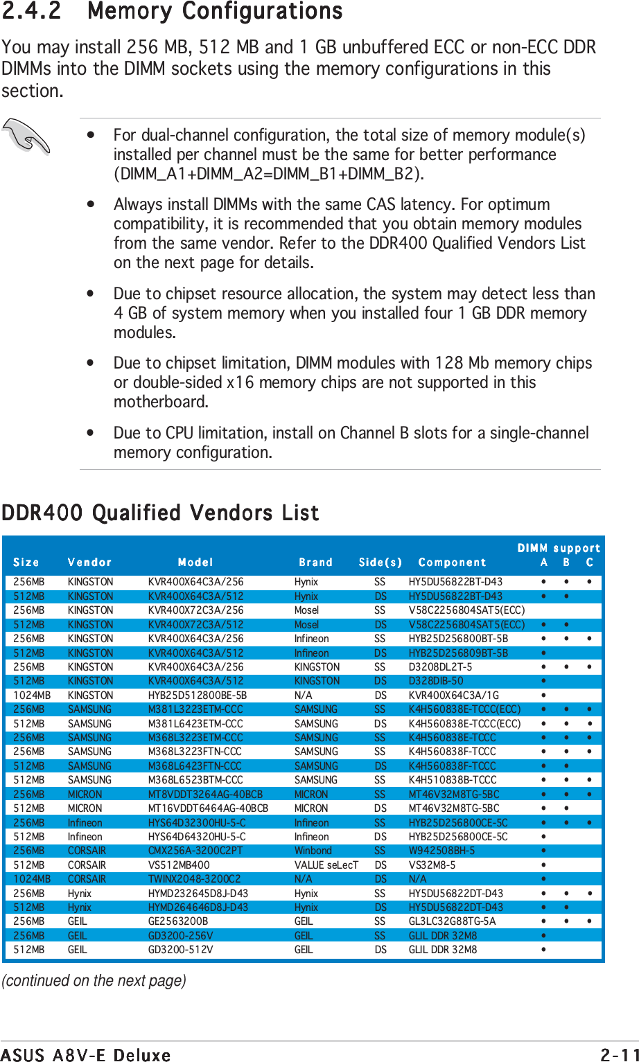
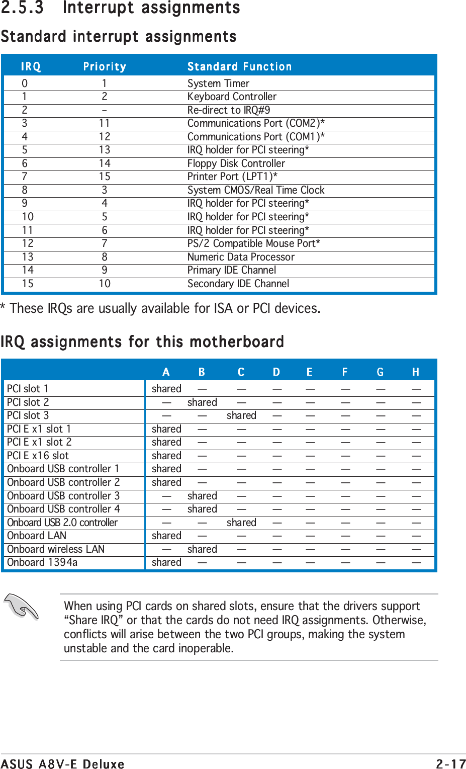
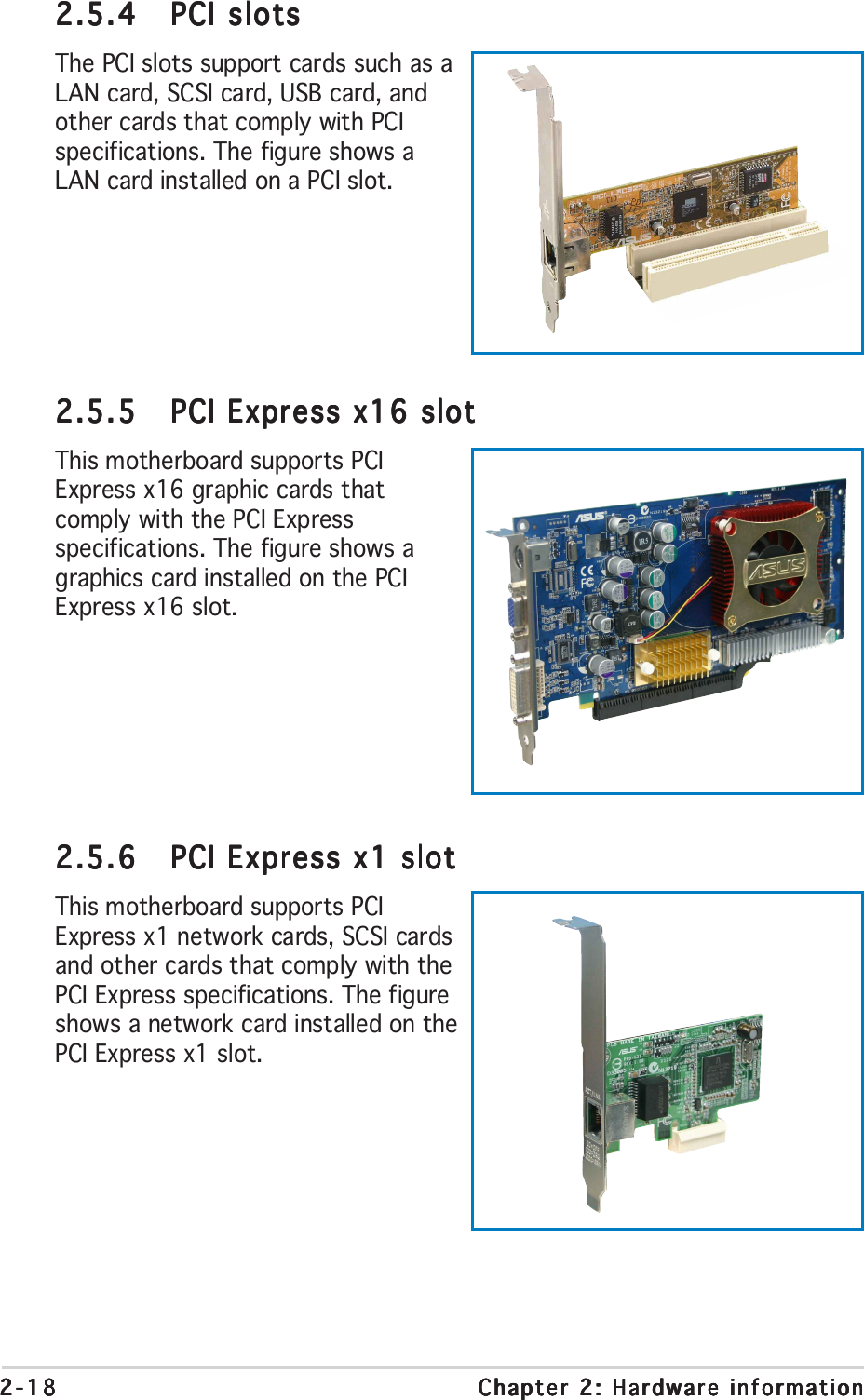
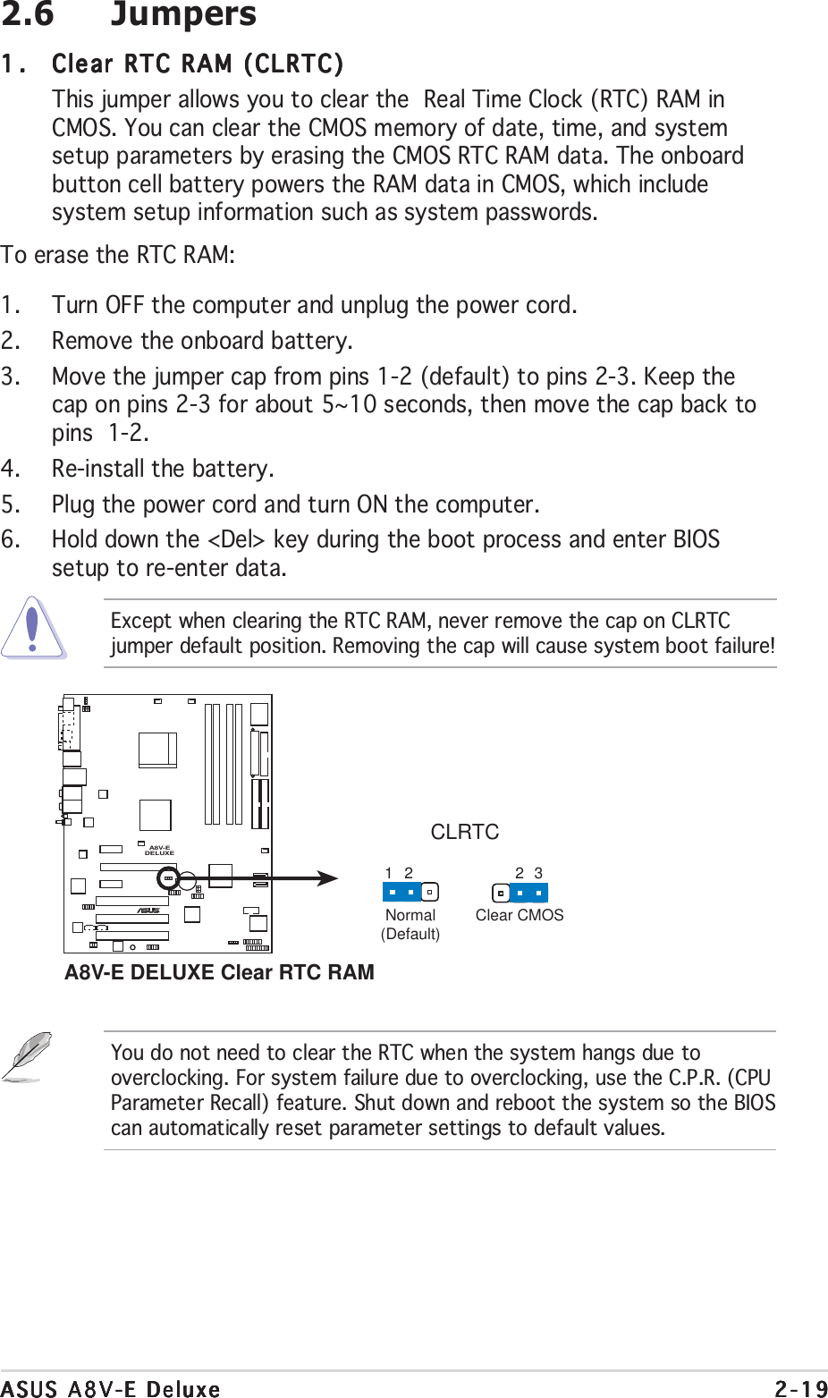
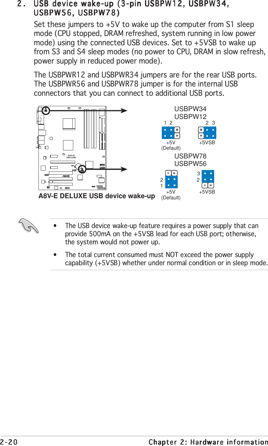
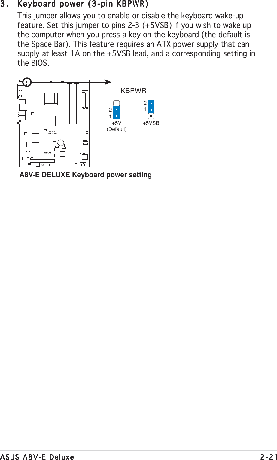
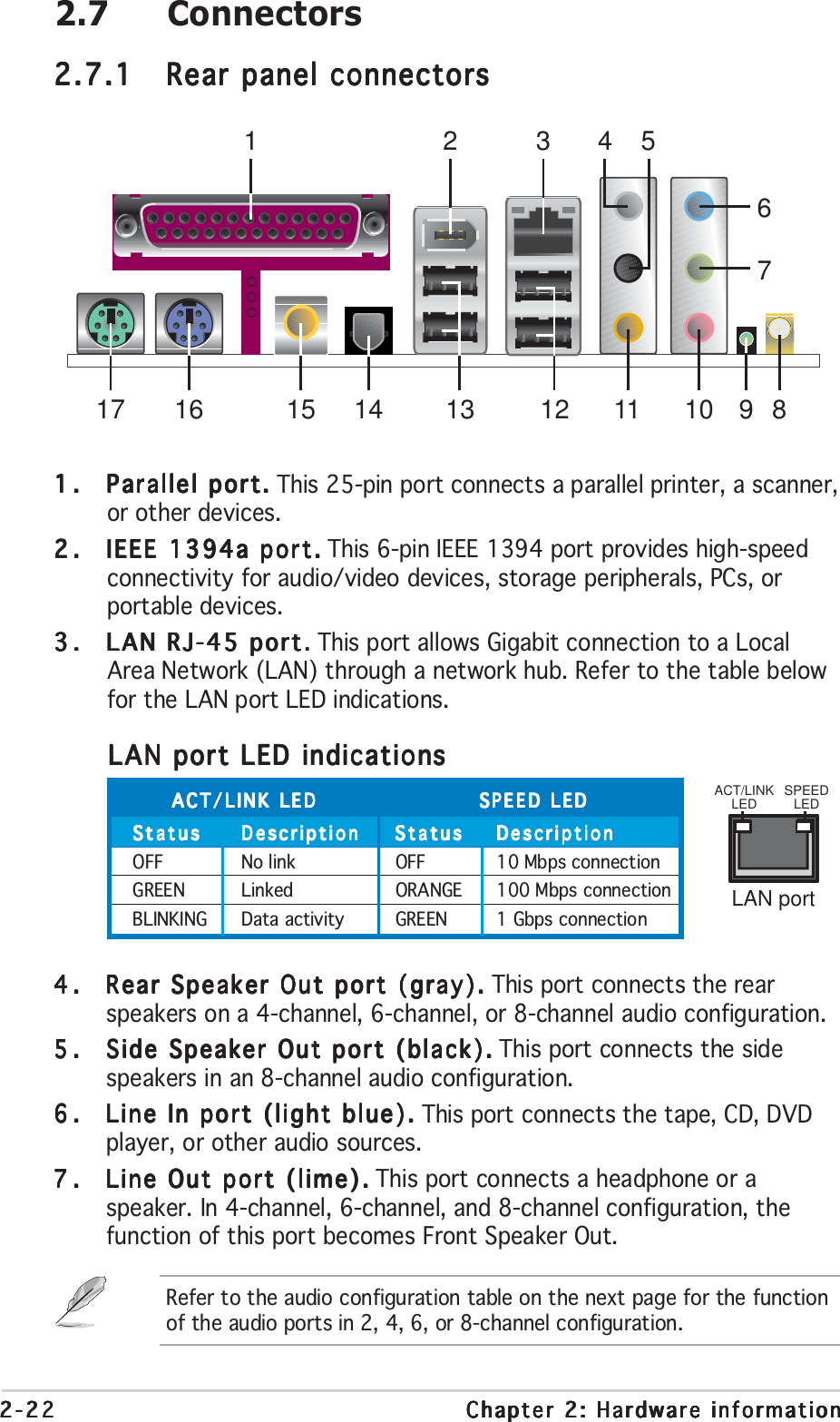
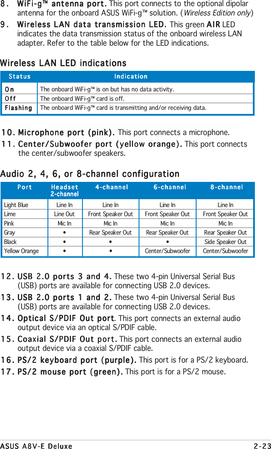
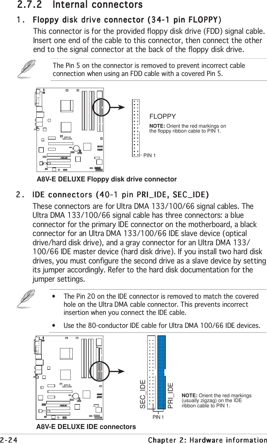
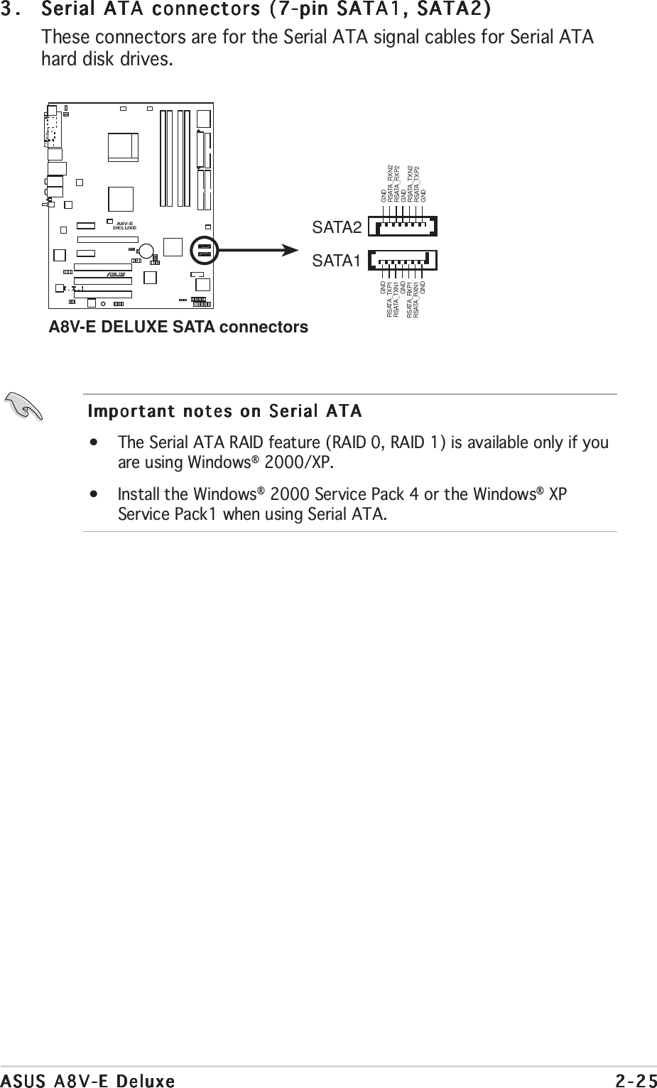
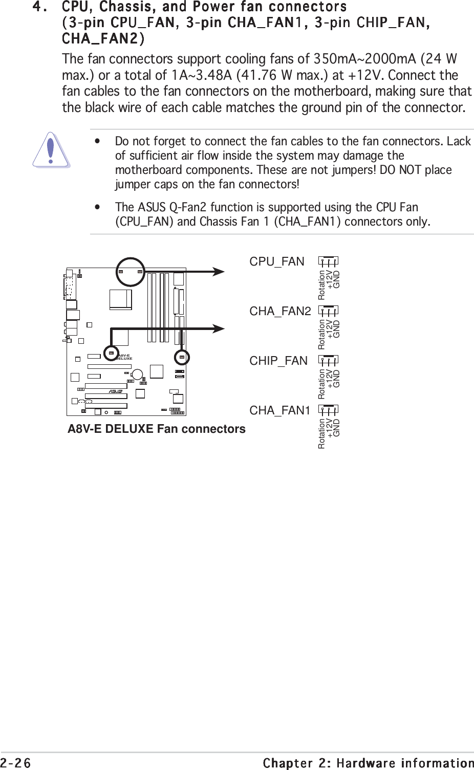
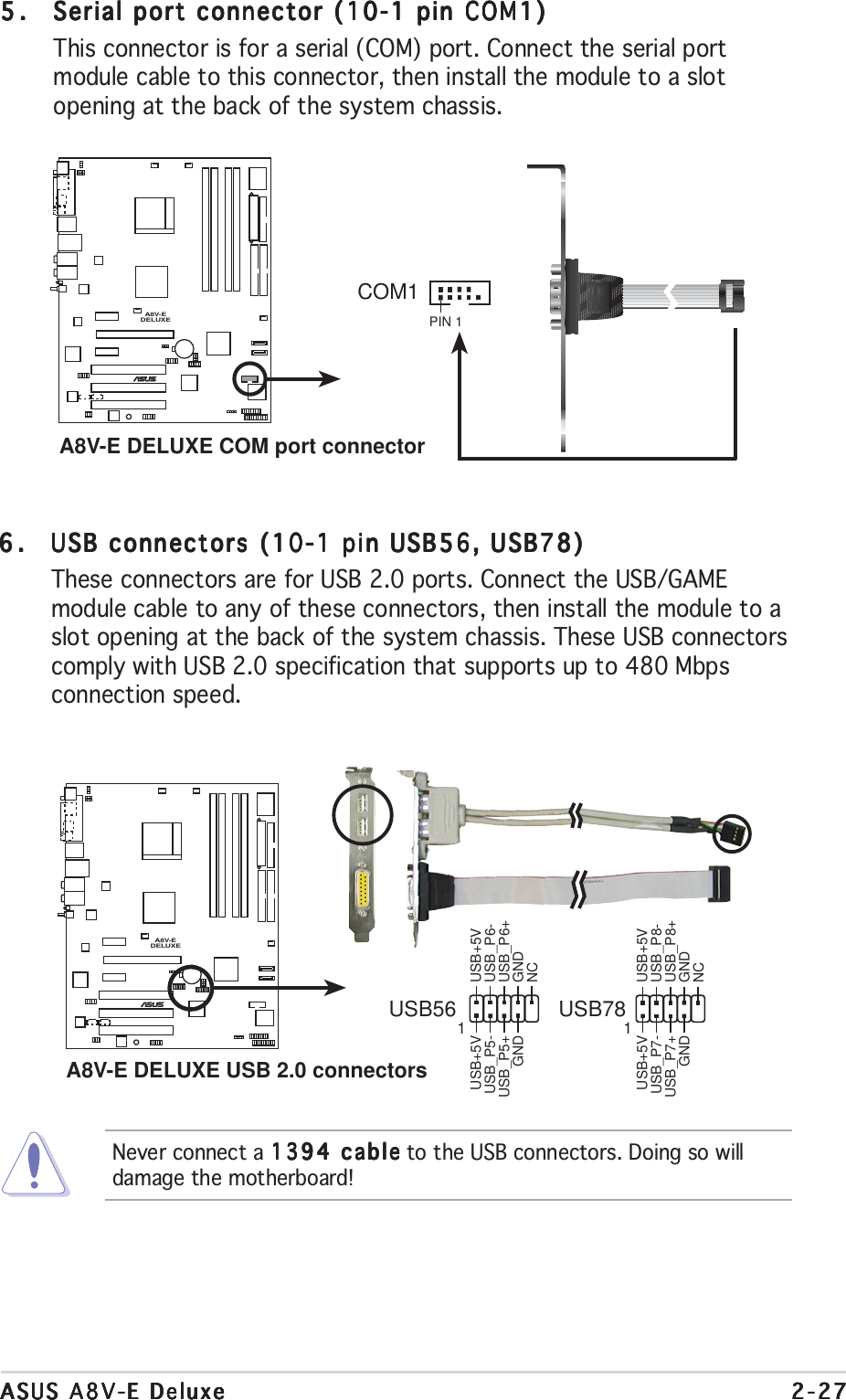
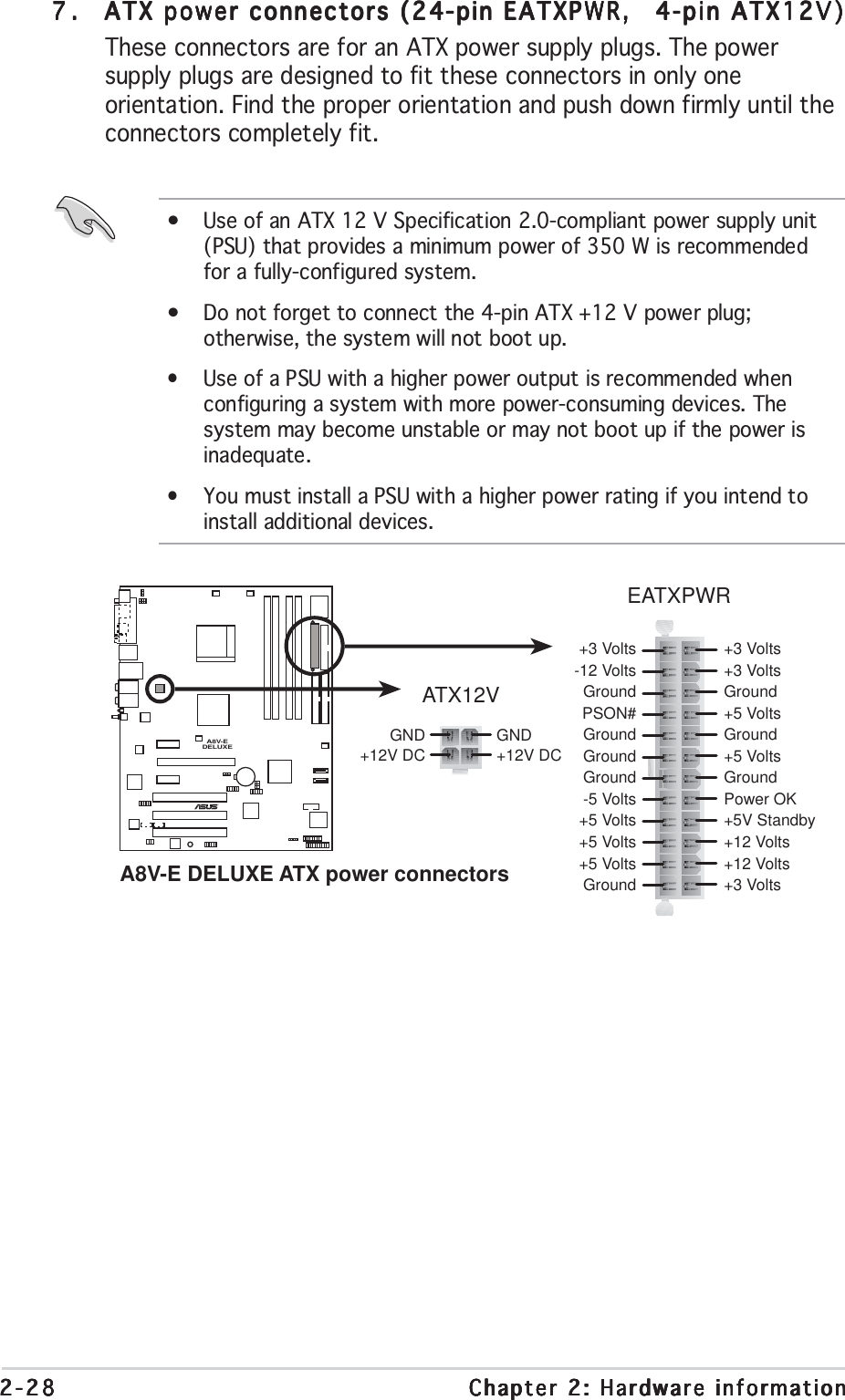
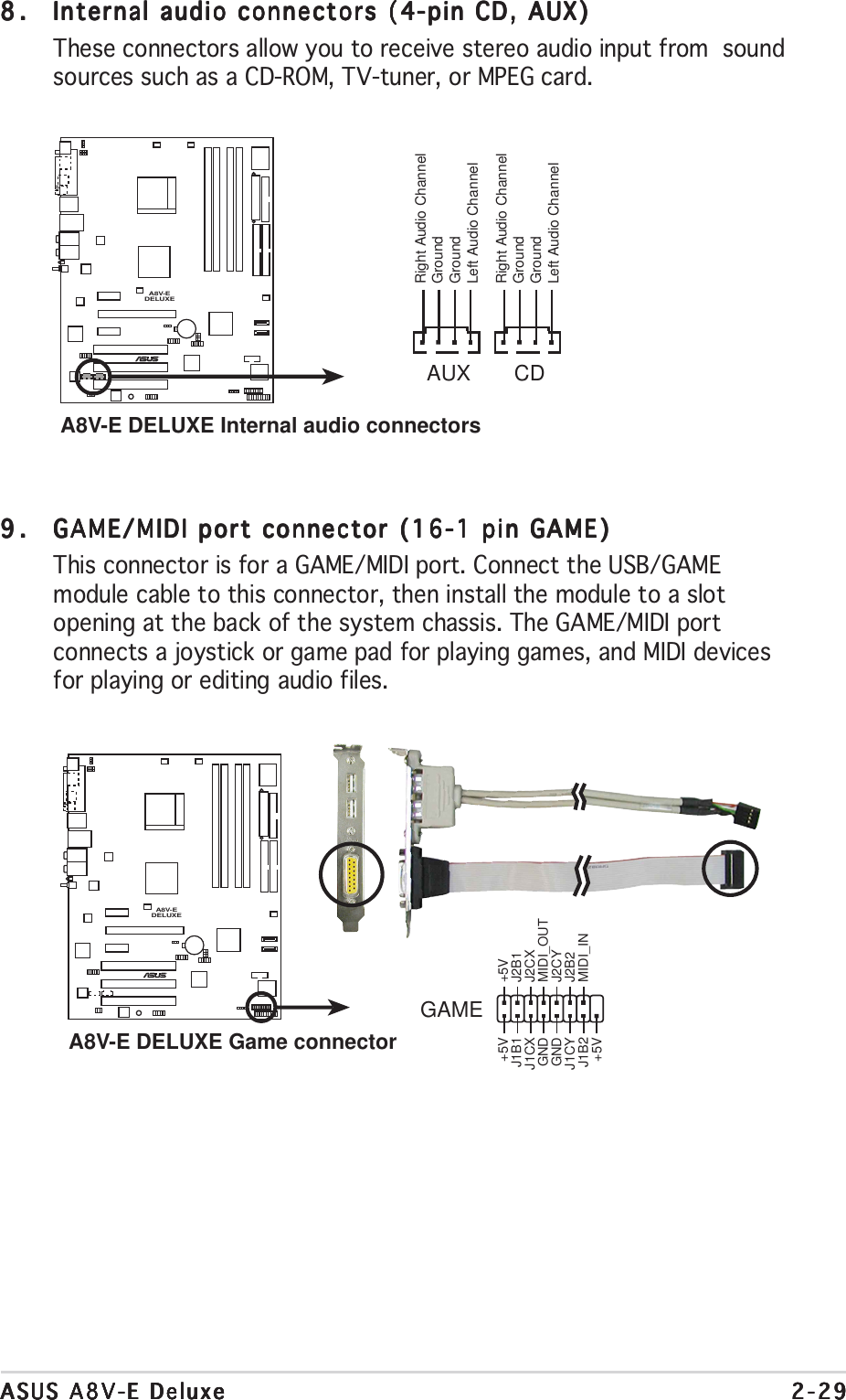
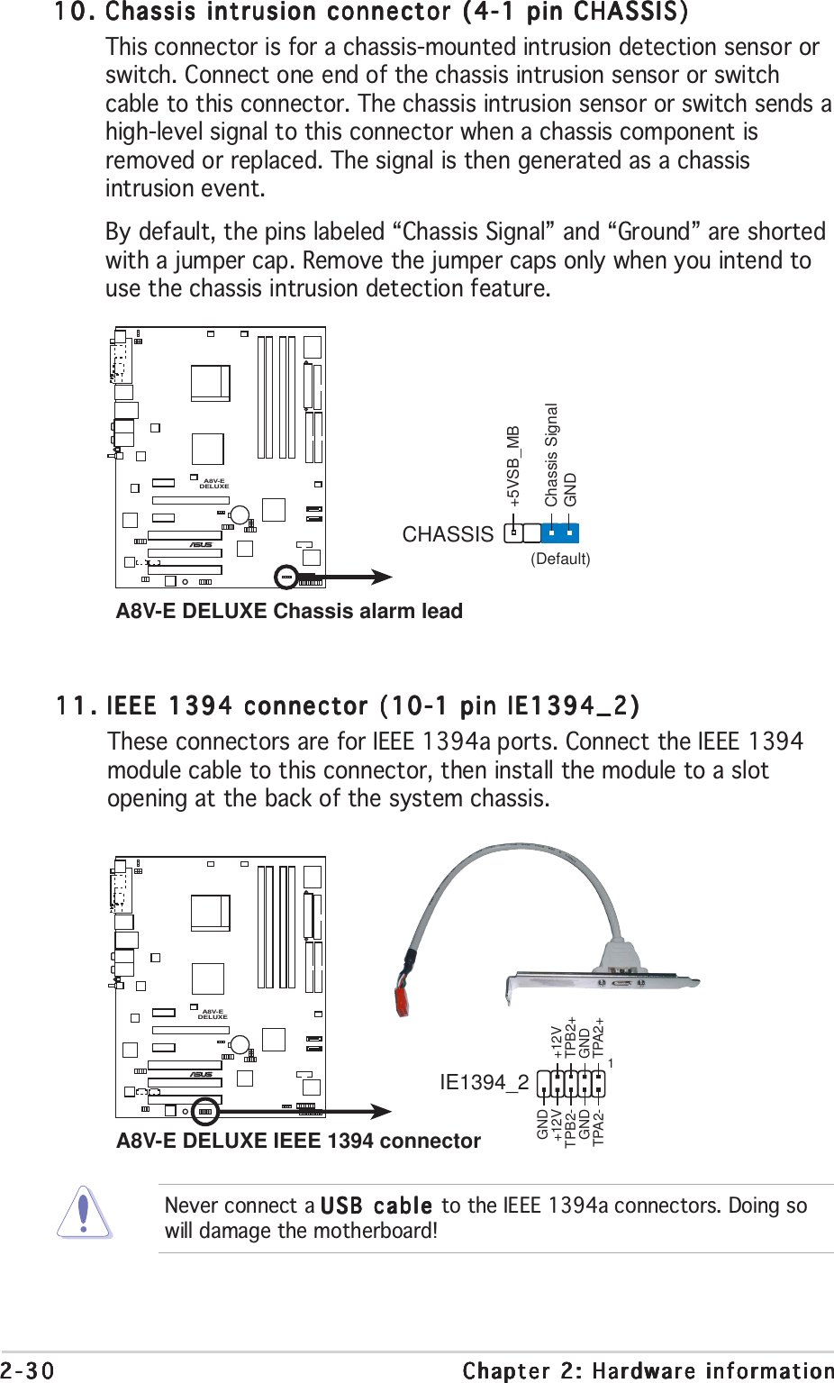
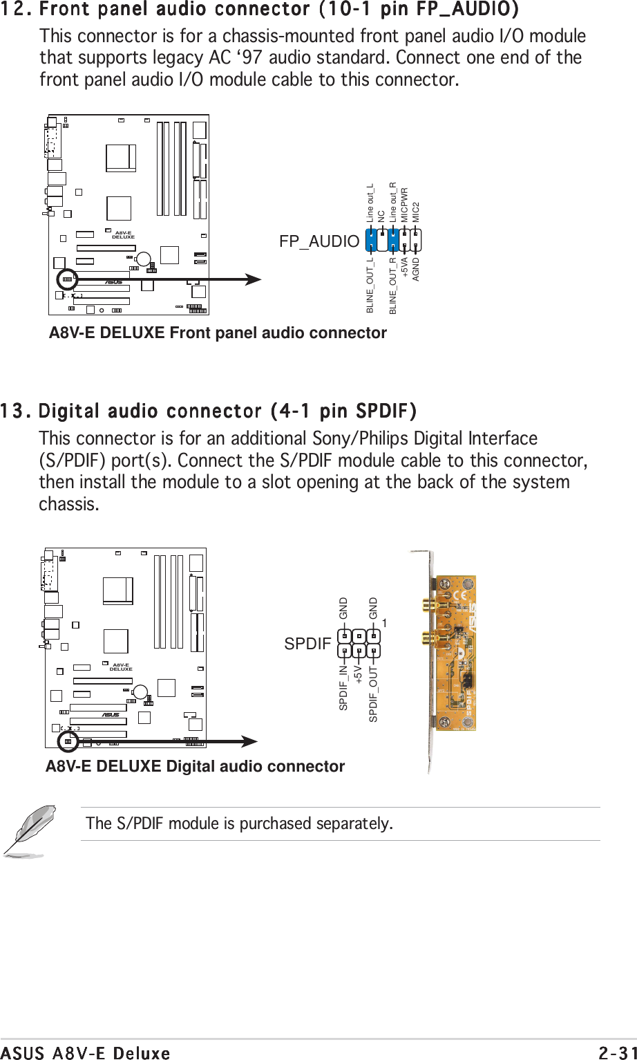
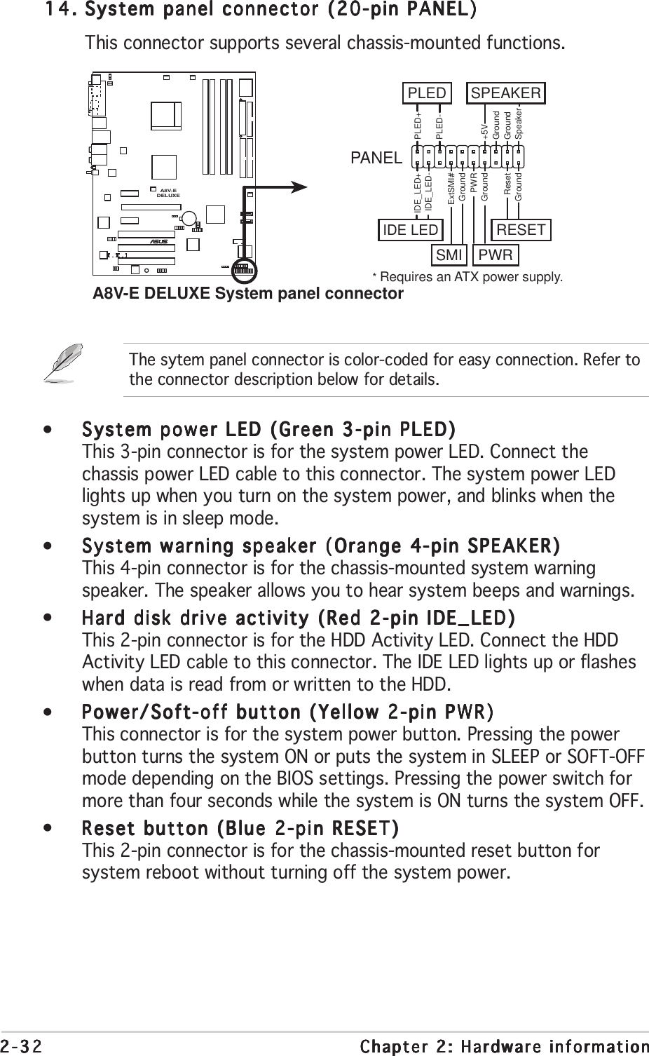
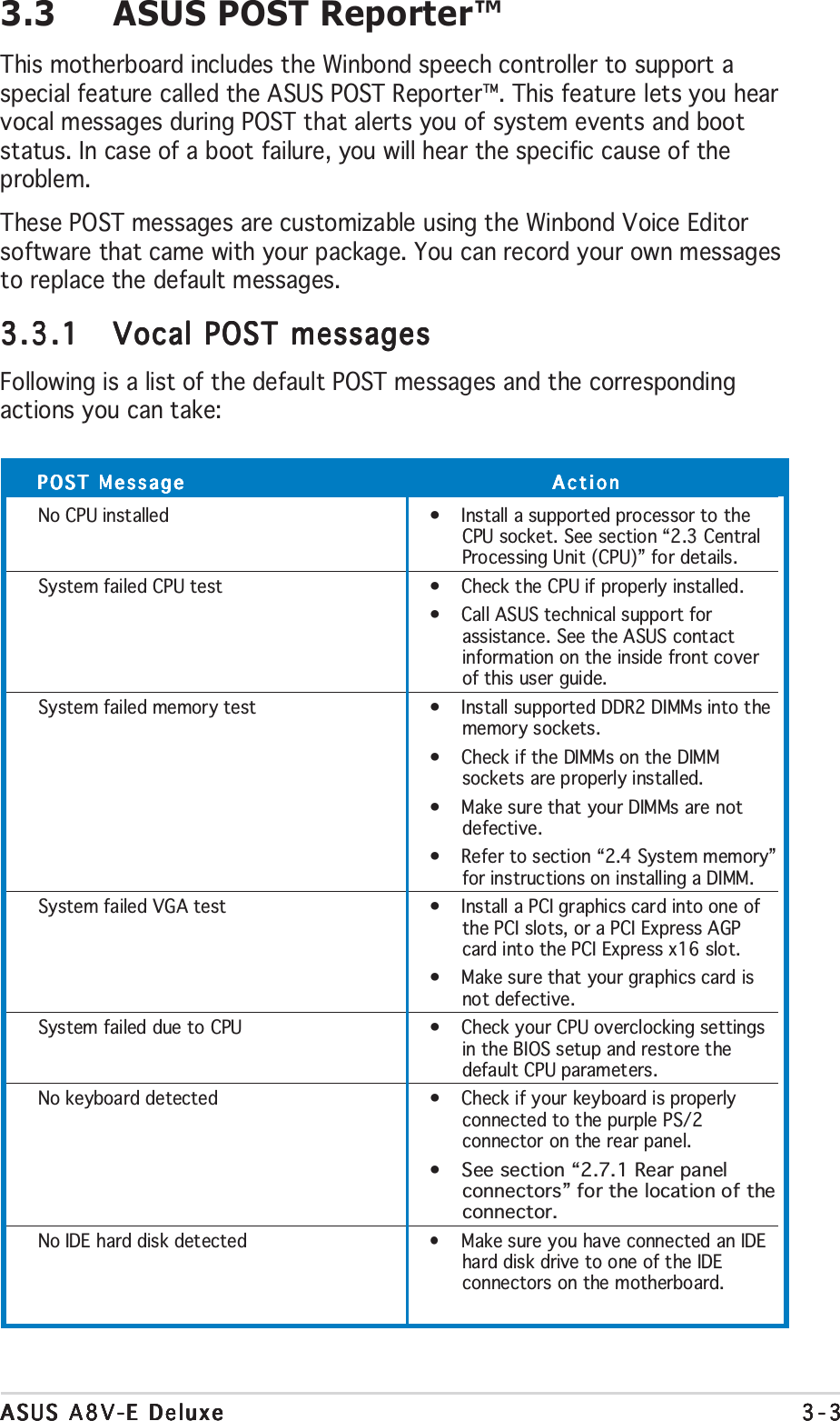
![xxxxxConventions used in this guideConventions used in this guideConventions used in this guideConventions used in this guideConventions used in this guideTo make sure that you perform certain tasks properly, take note of thefollowing symbols used throughout this manual.TypographyDANGER/WARNING: DANGER/WARNING: DANGER/WARNING: DANGER/WARNING: DANGER/WARNING: Information to prevent injury to yourselfwhen trying to complete a task.CAUTION:CAUTION:CAUTION:CAUTION:CAUTION: Information to prevent damage to the componentswhen trying to complete a task.NOTE: NOTE: NOTE: NOTE: NOTE: Tips and additional information to help you complete atask.IMPORTANT: IMPORTANT: IMPORTANT: IMPORTANT: IMPORTANT: Instructions that you MUST follow to complete atask.Bold textBold textBold textBold textBold text Indicates a menu or an item to selectItalicsUsed to emphasize a word or a phrase<Key> Keys enclosed in the less-than and greater-than sign meansthat you must press the enclosed keyExample: <Enter> means that you must press the Enter orReturn key<Key1+Key2+Key3> If you must press two or more keys simultaneously, thekey names are linked with a plus sign (+)Example: <Ctrl+Alt+D>Command Means that you must type the command exactly as shown,then supply the required item or value enclosed inbracketsExample: At the DOS prompt, type the command line:afudos /i[filename]afudos /iA8V-E.ROM](https://usermanual.wiki/ASUSTeK-Computer/MWOM4LA.USERS-MANUAL-1/User-Guide-503728-Page-10.png)