ASUSTeK Computer MWOM4LA MOTHERBOARD User Manual FRONT A8V E Deluxe P65
ASUSTeK Computer Inc MOTHERBOARD FRONT A8V E Deluxe P65
Contents
- 1. users manual
- 2. USERS MANUAL 1
- 3. USERS MANUAL 2
USERS MANUAL 1

Motherboard
A8V-E
Deluxe

iiii
iiii
ii
Copyright © 2004 ASUSTeK COMPUTER INC. All Rights Reserved.
No part of this manual, including the products and software described in it, may be reproduced,
transmitted, transcribed, stored in a retrieval system, or translated into any language in any form
or by any means, except documentation kept by the purchaser for backup purposes, without the
express written permission of ASUSTeK COMPUTER INC. (“ASUS”).
Product warranty or service will not be extended if: (1) the product is repaired, modified or
altered, unless such repair, modification of alteration is authorized in writing by ASUS; or (2)
the serial number of the product is defaced or missing.
ASUS PROVIDES THIS MANUAL “AS IS” WITHOUT WARRANTY OF ANY KIND, EITHER
EXPRESS OR IMPLIED, INCLUDING BUT NOT LIMITED TO THE IMPLIED WARRANTIES
OR CONDITIONS OF MERCHANTABILITY OR FITNESS FOR A PARTICULAR PURPOSE.
IN NO EVENT SHALL ASUS, ITS DIRECTORS, OFFICERS, EMPLOYEES OR AGENTS BE
LIABLE FOR ANY INDIRECT, SPECIAL, INCIDENTAL, OR CONSEQUENTIAL DAMAGES
(INCLUDING DAMAGES FOR LOSS OF PROFITS, LOSS OF BUSINESS, LOSS OF USE
OR DATA, INTERRUPTION OF BUSINESS AND THE LIKE), EVEN IF ASUS HAS BEEN
ADVISED OF THE POSSIBILITY OF SUCH DAMAGES ARISING FROM ANY DEFECT OR
ERROR IN THIS MANUAL OR PRODUCT.
SPECIFICATIONS AND INFORMATION CONTAINED IN THIS MANUAL ARE FURNISHED
FOR INFORMATIONAL USE ONLY, AND ARE SUBJECT TO CHANGE AT ANY TIME
WITHOUT NOTICE, AND SHOULD NOT BE CONSTRUED AS A COMMITMENT BY ASUS.
ASUS ASSUMES NO RESPONSIBILITY OR LIABILITY FOR ANY ERRORS OR
INACCURACIES THAT MAY APPEAR IN THIS MANUAL, INCLUDING THE PRODUCTS
AND SOFTWARE DESCRIBED IN IT.
Products and corporate names appearing in this manual may or may not be registered
trademarks or copyrights of their respective companies, and are used only for identification or
explanation and to the owners’ benefit, without intent to infringe.
E1781E1781
E1781E1781
E1781
First EditionFirst Edition
First EditionFirst Edition
First Edition
December 2004December 2004
December 2004December 2004
December 2004

iiiiii
iiiiii
iii
Contents
Notices ............................................................................................... vii
Safety information ............................................................................ viii
About this guide ................................................................................. ix
How this guide is organized .................................................... ix
Where to find more information .............................................. ix
Conventions used in this guide ................................................ x
Typography .......................................................................................... x
A8V-E Deluxe specifications summary ............................................... xi
Chapter 1: Product introductionChapter 1: Product introduction
Chapter 1: Product introductionChapter 1: Product introduction
Chapter 1: Product introduction
1.1 Welcome! .............................................................................. 1-1
1.2 Package contents ................................................................. 1-1
1.3 Special features .................................................................... 1-2
1.3.1 Product highlights................................................... 1-2
1.3.2 ASUS Proactive features ........................................ 1-4
1.3.3 Innovative ASUS features ....................................... 1-5
Chapter 2: Hardware informationChapter 2: Hardware information
Chapter 2: Hardware informationChapter 2: Hardware information
Chapter 2: Hardware information
2.1 Before you proceed .............................................................. 2-1
2.2 Motherboard overview .......................................................... 2-2
2.2.1 Placement direction ................................................ 2-2
2.2.2 Screw holes ............................................................ 2-2
2.2.3 Motherboard layout ................................................ 2-3
2.2.4 Layout Contents ..................................................... 2-4
2.3 Central Processing Unit (CPU) .............................................. 2-6
2.3.1 Overview ................................................................. 2-6
2.3.2 Installling the CPU ................................................... 2-6
2.3.3 Installing the heatsink and fan ................................ 2-8
2.4 System memory ................................................................. 2-10
2.4.1 Overview ............................................................... 2-10
2.4.2 Memory Configurations ......................................... 2-11
2.4.3 Installing a DIMM ................................................... 2-13
2.4.4 Removing a DIMM ................................................. 2-13
2.5 Expansion slots ................................................................... 2-14
2.5.1 Installing an expansion card .................................. 2-14
2.5.2 Configuring an expansion card.............................. 2-14

iviv
iviv
iv
Contents
2.5.3 Interrupt assignments .......................................... 2-17
2.5.4 PCI slots ................................................................ 2-18
2.5.5 PCI Express x16 slot ............................................. 2-18
2.5.6 PCI Express x1 slot ............................................... 2-18
2.6 Jumpers .............................................................................. 2-19
2.7 Connectors ......................................................................... 2-22
2.7.1 Rear panel connectors .......................................... 2-22
2.7.2 Internal connectors............................................... 2-24
Chapter 3: Powering upChapter 3: Powering up
Chapter 3: Powering upChapter 3: Powering up
Chapter 3: Powering up
3.1 Starting up for the first time................................................ 3-1
3.2 Powering off the computer .................................................. 3-2
3.2.1 Using the OS shut down function ........................... 3-2
3.2.2 Using the dual function power switch .................... 3-2
3.3 ASUS POST Reporter™ .......................................................... 3-3
3.3.1 Vocal POST messages ............................................ 3-3
3.3.2 Winbond Voice Editor ............................................. 3-5
Chapter 4: BIOS setupChapter 4: BIOS setup
Chapter 4: BIOS setupChapter 4: BIOS setup
Chapter 4: BIOS setup
4.1 Managing and updating your BIOS ........................................ 4-1
4.1.1 Creating a bootable floppy disk .............................. 4-1
4.1.2 Updating the BIOS .................................................. 4-2
4.1.3 Saving the current BIOS file .................................... 4-4
4.1.4 ASUS CrashFree BIOS 2 utility ................................ 4-5
4.1.5 ASUS EZ Flash utility .............................................. 4-7
4.1.6 ASUS Update utility ................................................ 4-8
4.2 BIOS setup program ........................................................... 4-11
4.2.1 BIOS menu screen ................................................. 4-12
4.2.2 Menu bar ............................................................... 4-12
4.2.3 Legend bar ........................................................... 4-13
4.2.4 Menu items ........................................................... 4-13
4.2.5 Sub-menu items ................................................... 4-13
4.2.6 Configuration fields .............................................. 4-13
4.2.8 General help .......................................................... 4-14
4.2.7 Pop-up window ..................................................... 4-14

vv
vv
v
Contents
4.3 Main menu .......................................................................... 4-15
4.3.1 System Time ......................................................... 4-15
4.3.2 System Date ......................................................... 4-15
4.3.3 Language .............................................................. 4-15
4.3.4 Legacy Diskette A ................................................ 4-15
4.3.5 Primary and Secondary IDE Master/Slave ............. 4-16
4.3.6 Installed Memory .................................................. 4-17
4.4 Advanced menu .................................................................. 4-18
4.4.1 CPU Configuration ................................................. 4-18
4.4.2 Chipset ................................................................. 4-19
4.4.3 PCI PnP ................................................................. 4-21
4.4.4 Onboard Devices Configuration ............................ 4-23
4.4.5 USB Configuration................................................. 4-25
4.4.6 JumperFree Configuration .................................... 4-26
4.4.7 LAN Cable Status ................................................. 4-30
4.4.8 PEG Link Mode ...................................................... 4-30
4.4.9 Speech Configuration ........................................... 4-31
4.4.10 Instant Music ........................................................ 4-32
4.5 Power menu ........................................................................ 4-33
4.5.1 ACPI Suspend Type............................................... 4-33
4.5.2 ACPI APIC Support ................................................ 4-33
4.5.3 APM Configuration ................................................ 4-34
4.5.4 Hardware Monitor ................................................. 4-36
4.6 Boot menu .......................................................................... 4-37
4.6.1 Boot Device Priority .............................................. 4-38
4.6.2 Removable Drives ................................................. 4-38
4.6.3 Hard Disk Drives ................................................... 4-39
4.6.4 CDROM Drives ....................................................... 4-39
4.6.5 Boot Settings Configuration ................................. 4-40
4.6.6 Security ................................................................ 4-42
4.7 Exit menu ........................................................................... 4-44
Chapter 5: Software supportChapter 5: Software support
Chapter 5: Software supportChapter 5: Software support
Chapter 5: Software support
5.1 Installing an operating system ............................................. 5-1
5.2 Support CD information ........................................................ 5-1

vivi
vivi
vi
5.2.1 Running the support CD ......................................... 5-1
5.2.2 Drivers menu .......................................................... 5-2
5.2.3 Utilities menu .......................................................... 5-4
5.2.4 ASUS Contact information ...................................... 5-6
5.2.5 Other information ................................................... 5-6
5.3 Software information ........................................................... 5-9
5.3.1 ASUS MyLogo2™ .................................................... 5-9
5.3.2 AI NET 2 ............................................................... 5-11
Using the Virtual Cable Tester™ ........................... 5-11
5.3.3 Audio configurations ............................................ 5-12
5.4 RAID configurations ............................................................ 5-18
5.4.1 Installing hard disks .............................................. 5-18
5.4.2 VIA RAID configurations ....................................... 5-19
5.5 Creating a RAID driver disk ................................................. 5-26
5.6 Cool ‘n’ Quiet!™ Technology ............................................... 5-27
5.6.1 Enabling Cool ‘n’ Quiet!™ Technology ................... 5-27
5.6.2 Launching the Cool ‘n’ Quiet!™ software .............. 5-28
Contents

viivii
viivii
vii
Notices
Federal Communications Commission StatementFederal Communications Commission Statement
Federal Communications Commission StatementFederal Communications Commission Statement
Federal Communications Commission Statement
This device complies with Part 15 of the FCC Rules. Operation is subject to the
following two conditions:
•
This device may not cause harmful interference, and
•
This device must accept any interference received including interference
that may cause undesired operation.
This equipment has been tested and found to comply with the limits for a
Class B digital device, pursuant to Part 15 of the FCC Rules. These limits are
designed to provide reasonable protection against harmful interference in a
residential installation. This equipment generates, uses and can radiate radio
frequency energy and, if not installed and used in accordance with
manufacturer’s instructions, may cause harmful interference to radio
communications. However, there is no guarantee that interference will not
occur in a particular installation. If this equipment does cause harmful
interference to radio or television reception, which can be determined by
turning the equipment off and on, the user is encouraged to try to correct the
interference by one or more of the following measures:
•
Reorient or relocate the receiving antenna.
•
Increase the separation between the equipment and receiver.
•
Connect the equipment to an outlet on a circuit different from that to
which the receiver is connected.
•
Consult the dealer or an experienced radio/TV technician for help.
The use of shielded cables for connection of the monitor to the graphics
card is required to assure compliance with FCC regulations. Changes or
modifications to this unit not expressly approved by the party
responsible for compliance could void the user’s authority to operate
this equipment.
FCC RF Radiation Exposure StatementFCC RF Radiation Exposure Statement
FCC RF Radiation Exposure StatementFCC RF Radiation Exposure Statement
FCC RF Radiation Exposure Statement
This equipment complies with the FCC RF radiation exposure limits set forth for
an uncontrolled environment. This equipment should be installed and operated
with a mininum distance of 20 cm between the radiator and your body.
Canadian Department of Communications StatementCanadian Department of Communications Statement
Canadian Department of Communications StatementCanadian Department of Communications Statement
Canadian Department of Communications Statement
This digital apparatus does not exceed the Class B limits for radio noise
emissions from digital apparatus set out in the Radio Interference Regulations
of the Canadian Department of Communications.
This class B digital apparatus complies with CanadianThis class B digital apparatus complies with Canadian
This class B digital apparatus complies with CanadianThis class B digital apparatus complies with Canadian
This class B digital apparatus complies with Canadian
ICES-003.ICES-003.
ICES-003.ICES-003.
ICES-003.

viiiviii
viiiviii
viii
Safety information
Electrical safetyElectrical safety
Electrical safetyElectrical safety
Electrical safety
•
To prevent electrical shock hazard, disconnect the power cable from
the electrical outlet before relocating the system.
•
When adding or removing devices to or from the system, ensure that
the power cables for the devices are unplugged before the signal cables
are connected. If possible, disconnect all power cables from the existing
system before you add a device.
•
Before connecting or removing signal cables from the motherboard,
ensure that all power cables are unplugged.
•
Seek professional assistance before using an adapter or extension cord.
These devices could interrupt the grounding circuit.
•
Make sure that your power supply is set to the correct voltage in your
area. If you are not sure about the voltage of the electrical outlet you
are using, contact your local power company.
•
If the power supply is broken, do not try to fix it by yourself. Contact a
qualified service technician or your retailer.
Operation safetyOperation safety
Operation safetyOperation safety
Operation safety
•
Before installing the motherboard and adding devices on it, carefully read
all the manuals that came with the package.
•
Before using the product, make sure all cables are correctly connected
and the power cables are not damaged. If you detect any damage,
contact your dealer immediately.
•
To avoid short circuits, keep paper clips, screws, and staples away from
connectors, slots, sockets and circuitry.
•
Avoid dust, humidity, and temperature extremes. Do not place the
product in any area where it may become wet.
•
Place the product on a stable surface.
•
If you encounter technical problems with the product, contact a qualified
service technician or your retailer.

ixix
ixix
ix
About this guide
This user guide contains the information you need when installing and
configuring the motherboard.
How this guide is organizedHow this guide is organized
How this guide is organizedHow this guide is organized
How this guide is organized
This manual contains the following parts:
••
••
•Chapter 1: Product introductionChapter 1: Product introduction
Chapter 1: Product introductionChapter 1: Product introduction
Chapter 1: Product introduction
This chapter describes the features of the motherboard and the new
technology it supports.
••
••
•Chapter 2: Hardware informationChapter 2: Hardware information
Chapter 2: Hardware informationChapter 2: Hardware information
Chapter 2: Hardware information
This chapter lists the hardware setup procedures that you have to
perform when installing system components. It includes description of
the switches, jumpers, and connectors on the motherboard.
••
••
•Chapter 3: Powering upChapter 3: Powering up
Chapter 3: Powering upChapter 3: Powering up
Chapter 3: Powering up
This chapter describes the power up sequence, the vocal POST
messages, and ways of shutting down the system.
••
••
•Chapter 4: BIOS setupChapter 4: BIOS setup
Chapter 4: BIOS setupChapter 4: BIOS setup
Chapter 4: BIOS setup
This chapter tells how to change system settings through the BIOS
Setup menus. Detailed descriptions of the BIOS parameters are also
provided.
••
••
•Chapter 5: Software supportChapter 5: Software support
Chapter 5: Software supportChapter 5: Software support
Chapter 5: Software support
This chapter describes the contents of the support CD that comes
with the motherboard package.
Where to find more informationWhere to find more information
Where to find more informationWhere to find more information
Where to find more information
Refer to the following sources for additional information and for product
and software updates.
1.1.
1.1.
1. ASUS websitesASUS websites
ASUS websitesASUS websites
ASUS websites
The ASUS website provides updated information on ASUS hardware
and software products. Refer to the ASUS contact information.
2.2.
2.2.
2. Optional documentationOptional documentation
Optional documentationOptional documentation
Optional documentation
Your product package may include optional documentation, such as
warranty flyers, that may have been added by your dealer. These
documents are not part of the standard package.

xx
xx
x
Conventions used in this guideConventions used in this guide
Conventions used in this guideConventions used in this guide
Conventions used in this guide
To make sure that you perform certain tasks properly, take note of the
following symbols used throughout this manual.
Typography
DANGER/WARNING: DANGER/WARNING:
DANGER/WARNING: DANGER/WARNING:
DANGER/WARNING: Information to prevent injury to yourself
when trying to complete a task.
CAUTION:CAUTION:
CAUTION:CAUTION:
CAUTION: Information to prevent damage to the components
when trying to complete a task.
NOTE: NOTE:
NOTE: NOTE:
NOTE: Tips and additional information to help you complete a
task.
IMPORTANT: IMPORTANT:
IMPORTANT: IMPORTANT:
IMPORTANT: Instructions that you MUST follow to complete a
task.
Bold textBold text
Bold textBold text
Bold text Indicates a menu or an item to select
Italics
Used to emphasize a word or a phrase
<Key> Keys enclosed in the less-than and greater-than sign means
that you must press the enclosed key
Example: <Enter> means that you must press the Enter or
Return key
<Key1+Key2+Key3> If you must press two or more keys simultaneously, the
key names are linked with a plus sign (+)
Example: <Ctrl+Alt+D>
Command Means that you must type the command exactly as shown,
then supply the required item or value enclosed in
brackets
Example: At the DOS prompt, type the command line:
afudos /i[filename]
afudos /iA8V-E.ROM
xixi
xixi
xi
A8V-E Deluxe specifications summary
(continued on the next page)
CPUCPU
CPUCPU
CPU
ChipsetChipset
ChipsetChipset
Chipset
System BusSystem Bus
System BusSystem Bus
System Bus
MemoryMemory
MemoryMemory
Memory
Expansion slotsExpansion slots
Expansion slotsExpansion slots
Expansion slots
StorageStorage
StorageStorage
Storage
AI AudioAI Audio
AI AudioAI Audio
AI Audio
Wireless LANWireless LAN
Wireless LANWireless LAN
Wireless LAN
LANLAN
LANLAN
LAN
IEEE 1394IEEE 1394
IEEE 1394IEEE 1394
IEEE 1394
USBUSB
USBUSB
USB
Socket 939 for AMD Athlon™ 64FX/AMD Athlon™ 64
processor
Supports AMD 64 architecture that enables simultaneous
32-bit and 64-bit architecture
Supports AMD Cool ‘n’ Quiet! Technology
Northbridge: VIA
®
K8T890
Southbridge: VIA
®
VT8237R
2000 MT/s
Dual-channel memory architecture
4 x 184-pin DIMM sockets support ECC/non-ECC
unbufferred 400/333/266 MHz DDR memory modules
Supports up to 4 GB system memory
1 x PCI Express x16 slot for discrete graphics card
2 x PCI Express x1 slots
3 x PCI slots
VIA
®
VT8237R Southbridge supports:
-2 x Ultra DMA 133/100/66/33
-2 x Serial ATA with RAID 0 and RAID 1
Realtek
®
ALC850 8-channel CODEC
1 x Coaxial S/PDIF out port
1 x Optical S/PDIF out port
Supports Audio Sensing and Enumeration Technology
WiFi-g™ wireless solution provides:
- support for IEEE 802.11g/b standard
- up to 54Mbps wireless data transmission
- Software Access Point (Soft AP) feature on
Windows
®
XP and 2003 Server
Marvell
®
88E8053 PCI Express™ Gigabit LAN controller
Supports Marvell
®
Virtual Cable Tester technology
Supports POST Network-diagnostic program
T1 TSB43AB22A 1394a controller supports:
- 1 x IEEE 1394 internal connector
- 1 x IEEE 1394 port
Supports up to 8 USB 2.0 ports

xiixii
xiixii
xii
A8V-E Deluxe specifications summary
AI OverclockingAI Overclocking
AI OverclockingAI Overclocking
AI Overclocking
Special featuresSpecial features
Special featuresSpecial features
Special features
BIOS featuresBIOS features
BIOS featuresBIOS features
BIOS features
Rear panelRear panel
Rear panelRear panel
Rear panel
InternalInternal
InternalInternal
Internal
connectorsconnectors
connectorsconnectors
connectors
ASUS AI Overclocking (Intelligent CPU frequency tuner)
ASUS C.P.R. (CPU Parameter Recall)
ASUS JumperFree
CPU, Memory, and chipset voltage adjustable
Stepless Frequency Selection(SFS) from 200 MHz up
to 400 MHz at 1 MHz increment
ASUS Wi-Fi@HOME
ASUS Post Reporter™
ASUS Q-Fan2
ASUS CrashFree BIOS 2
ASUS Multi-language BIOS
ASUS MyLogo2
ASUS Instant Music
4 MB Flash ROM, Phoenix-Award BIOS, PnP, DMI2.0,
WfM2.0, SM BIOS 2.3
1 x Parallel port
1 x IEEE 1394 port
1 x LAN (RJ-45) port
1 x WiFi-g™ antenna port
1 x Wireless LAN LED
4 x USB 2.0 ports
1 x Optical S/PDIF out port
1 x Coaxial S/PDIF out port
1 x PS/2 keyboard port
1 x PS/2 mouse port
8-channel audio port
1 x Floppy disk drive connector
2 x IDE connectors
2 x Serial ATA connectors
1 x CPU fan connector
1 x Power fan connector
2 x Chassis fan connector
1 x Serial port connector (COM port)
1 x 24-pin ATX power connector
1 x 4-pin ATX 12 V power connector
2 x USB 2.0 connectors for 4 additional USB 2.0 ports
1 x Internal audio connectors
1 x IEEE 1394 connector
1 x GAME/MIDI connector
1 x Chassis intrusion connector
1 x Front panel audio connector
System panel connector
(continued on the next page)

xiiixiii
xiiixiii
xiii
A8V-E Deluxe specifications summary
PowerPower
PowerPower
Power
RequirementRequirement
RequirementRequirement
Requirement
Form FactorForm Factor
Form FactorForm Factor
Form Factor
Support CDSupport CD
Support CDSupport CD
Support CD
contentscontents
contentscontents
contents
ATX power supply (with 24-pin and 4-pin 12 V plugs)
ATX 12 V 2.0 compliant
ATX form factor: 12 in x 9.6 in (30.5 cm x 24.4 cm)
Device drivers
ASUS PC Probe
ASUS Live Update Utility
Antivirus software (OEM version)
WiFi-g™ One-touch wizard
*Specifications are subject to change without notice.

xivxiv
xivxiv
xiv
1
Product
introduction
This chapter describes the motherboard
features and the new technologies
it supports.

ASUS A8V-E DeluxeASUS A8V-E Deluxe
ASUS A8V-E DeluxeASUS A8V-E Deluxe
ASUS A8V-E Deluxe
Chapter summary
1.1 Welcome! .............................................................................. 1-1
1.2 Package contents ................................................................. 1-1
1.3 Special features .................................................................... 1-2

ASUS A8V-E DeluxeASUS A8V-E Deluxe
ASUS A8V-E DeluxeASUS A8V-E Deluxe
ASUS A8V-E Deluxe 1-11-1
1-11-1
1-1
1.1 Welcome!
Thank you for buying an ASUSThank you for buying an ASUS
Thank you for buying an ASUSThank you for buying an ASUS
Thank you for buying an ASUS
®®
®®
®
A8V-E Deluxe motherboard! A8V-E Deluxe motherboard!
A8V-E Deluxe motherboard! A8V-E Deluxe motherboard!
A8V-E Deluxe motherboard!
The motherboard delivers a host of new features and latest technologies,
making it another standout in the long line of ASUS quality motherboards!
Before you start installing the motherboard, and hardware devices on it,
check the items in your package with the list below.
If any of the above items is damaged or missing, contact your retailer.
1.2 Package contents
Check your motherboard package for the following items.
MotherboardMotherboard
MotherboardMotherboard
Motherboard ASUS A8V-E Deluxe motherboard
I/O modulesI/O modules
I/O modulesI/O modules
I/O modules IEEE1394 (1 port) module
Serial port module (COM port)
USB 2.0 (2 ports) and GAME (1 port) module
CablesCables
CablesCables
Cables 2 x Serial ATA signal cables
1 x Serial ATA power cables (dual plugs)
2 x Ultra DMA/133 cables
40-conductor IDE cable
Floppy disk drive cable
AccessoriesAccessories
AccessoriesAccessories
Accessories Dipolar wireless LAN antenna
I/O shield
Application CDsApplication CDs
Application CDsApplication CDs
Application CDs ASUS motherboard support CD
InterVideo
®
WinDVD Suite
®
DocumentationDocumentation
DocumentationDocumentation
Documentation User guide

1-21-2
1-21-2
1-2 Chapter 1: Product introductionChapter 1: Product introduction
Chapter 1: Product introductionChapter 1: Product introduction
Chapter 1: Product introduction
1.3 Special features
1.3.11.3.1
1.3.11.3.1
1.3.1 Product highlightsProduct highlights
Product highlightsProduct highlights
Product highlights
Latest processor technology Latest processor technology
Latest processor technology Latest processor technology
Latest processor technology
The AMD Athlon™ 64FX and Athlon™ 64 desktop processors are based on
AMD’s 64-bit and 32-bit architecture, which represents the landmark
introduction of the industry’s first x86-64 technology. These processors
provide a dramatic leap forward in compatibility, performance, investment
protection, and reduced total cost of ownership and development.
See page 2-6.
HyperTransport™ Technology HyperTransport™ Technology
HyperTransport™ Technology HyperTransport™ Technology
HyperTransport™ Technology
HyperTransport™ Technology is a high-speed, low latency, point-to-point
link designed to increase the communication speed between integrated
circuits in computers, networking and telecommunicatons equipment up to
48 times faster than other existing technologies.
AMD Cool ‘n’ Quiet!™ Technology AMD Cool ‘n’ Quiet!™ Technology
AMD Cool ‘n’ Quiet!™ Technology AMD Cool ‘n’ Quiet!™ Technology
AMD Cool ‘n’ Quiet!™ Technology
The motherboard supports the AMD Cool ‘n’ Quiet!™ Technology that
dynamically and automatically changes the CPU speed, voltage and amount
of power depending on the task the CPU performs. See pages 4-18 and
5-27 for details.
Dual Channel DDR memory support Dual Channel DDR memory support
Dual Channel DDR memory support Dual Channel DDR memory support
Dual Channel DDR memory support
Employing the Double Data Rate (DDR) memory technology, the
motherboard supports up to 4GB of system memory using DDR400/333/
266 DIMMs. The ultra-fast 400MHz memory bus delivers the required
bandwidth for the latest 3D graphics, multimedia, and Internet applications.
See page 2-10.
Serial ATA technology with RAID 0/1 support Serial ATA technology with RAID 0/1 support
Serial ATA technology with RAID 0/1 support Serial ATA technology with RAID 0/1 support
Serial ATA technology with RAID 0/1 support
The motherboard supports the Serial ATA technology through the Serial ATA
interfaces. The SATA specification allows for thinner, more flexible cables
with lower pin count, reduced voltage requirement, and up to 150 MB/s data
transfer rate. With the VIA VT8237R RAID controller onboard, the
motherboard supports RAID 0 and RAID 1 configuration using Serial ATA
hard disk drives. See pages 2-25 and 5-18 for details.

ASUS A8V-E DeluxeASUS A8V-E Deluxe
ASUS A8V-E DeluxeASUS A8V-E Deluxe
ASUS A8V-E Deluxe 1-31-3
1-31-3
1-3
PCI Express™ interface PCI Express™ interface
PCI Express™ interface PCI Express™ interface
PCI Express™ interface
The motherboard fully supports PCI Express, the latest I/O interconnect
technology that speeds up the PCI bus. PCI Express features point-to-point
serial interconnections between devices and allows higher clockspeeds by
carrying data in packets. This high speed interface is software compatible with
existing PCI specifications. See page 2-18 for details.
AI Audio technology AI Audio technology
AI Audio technology AI Audio technology
AI Audio technology
The motherboard supports 8-channel audio through the onboard ALC850
CODEC with 16-bit DAC, a stereo 16-bit ADC, and an AC97 2.3 compatible
multi-channel audio designed for PC multimedia systems. It also provides
Jack-Sensing function, S/PDIF out support, interrupt capability and includes
the Realtek
®
proprietary UAJ
®
(Universal Audio Jack) technology. See pages
2-22, 2-23 and 5-12 for details.
S/PDIF digital sound ready S/PDIF digital sound ready
S/PDIF digital sound ready S/PDIF digital sound ready
S/PDIF digital sound ready
The motherboard supports the S/PDIF In/Out function through the S/PDIF
interfaces on the rear panel and at midboard. The S/PDIF technology turns
your computer into a high-end entertainment system with digital connectivity
to powerful audio and speaker systems. See page 2-23 for details.
IEEE 1394a support IEEE 1394a support
IEEE 1394a support IEEE 1394a support
IEEE 1394a support
The IEEE 1394a interface provides high-speed and flexible PC connectivity
to a wide range of peripherals and devices compliant to the IEEE 1394a
standard. The IEEE 1394a interface allows up to 400 Mbps transfer rates
through simple, low-cost, high-bandwidth asynchronous (real-time) data
interfacing between computers, peripherals, and consumer electronic
devices such as camcorders, VCRs, printers, TVs, and digital cameras. See
pages 2-22 and 2-30 for details.
USB 2.0 technology USB 2.0 technology
USB 2.0 technology USB 2.0 technology
USB 2.0 technology
The motherboard implements the Universal Serial Bus (USB) 2.0
specification, dramatically increasing the connection speed from the
12 Mbps bandwidth on USB 1.1 to a fast 480 Mbps on USB 2.0. USB 2.0 is
backward compatible with USB 1.1. See pages 2-23, 2-27 and 4-25 for
details.
1-41-4
1-41-4
1-4 Chapter 1: Product introductionChapter 1: Product introduction
Chapter 1: Product introductionChapter 1: Product introduction
Chapter 1: Product introduction
1.3.21.3.2
1.3.21.3.2
1.3.2 ASUS Proactive featuresASUS Proactive features
ASUS Proactive featuresASUS Proactive features
ASUS Proactive features
ASUS WiFi-g™ ASUS WiFi-g™
ASUS WiFi-g™ ASUS WiFi-g™
ASUS WiFi-g™
ASUS WiFi-g™ is an IEEE 802.11g-compliant wireless LAN adapter that
allows data transmission of up to 54 Mbps using the 2.4 GHz frequency
band. ASUS provides full software application support and a user-friendly wizard
to help you set up your wireless local area network effortlessly. The ASUS
WiFi-g™ is backward compatible with IEEE 802.11b devices. See page 2-23.
AI NOS™ (Non-Delay Overclocking System) AI NOS™ (Non-Delay Overclocking System)
AI NOS™ (Non-Delay Overclocking System) AI NOS™ (Non-Delay Overclocking System)
AI NOS™ (Non-Delay Overclocking System)
ASUS Non-delay Overclocking System™ (NOS) is a technology that
auto-detects the CPU loading and dynamically overclocks the CPU speed
only when needed. See page 4-26 for details.
AI NET 2 AI NET 2
AI NET 2 AI NET 2
AI NET 2
AI NET 2 is a BIOS-based diagnostic tool that detects and reports Ethernet
cable faults and shorts. With this utility, you can easily monitor the
condition of the Ethernet cable(s) connected to the LAN (RJ-45) port(s).
During the bootup process, AI NET 2 immediately diagnoses the LAN
cable(s) and reports shorts and faults up to 100 meters at 1 meter
accuracy. See pages 4-30 and 5-11 for details.
Temperature, fan, and voltage monitoringTemperature, fan, and voltage monitoring
Temperature, fan, and voltage monitoringTemperature, fan, and voltage monitoring
Temperature, fan, and voltage monitoring
The CPU temperature is monitored by the ASIC (integrated in the Winbond
Super I/O) to prevent overheating and damage. The system fan rotations
per minute (RPM) is monitored for timely failure detection. The ASIC
monitors the voltage levels to ensure stable supply of current for critical
components. See section “4.5.4 Hardware Monitor” on page 4-36.

ASUS A8V-E DeluxeASUS A8V-E Deluxe
ASUS A8V-E DeluxeASUS A8V-E Deluxe
ASUS A8V-E Deluxe 1-51-5
1-51-5
1-5
1.3.31.3.3
1.3.31.3.3
1.3.3 Innovative ASUS featuresInnovative ASUS features
Innovative ASUS featuresInnovative ASUS features
Innovative ASUS features
Precision Tweaker Precision Tweaker
Precision Tweaker Precision Tweaker
Precision Tweaker
Designed for overclocking aficionados, this feature allows you to gradually
increase the CPU and memory voltage to achieve maximum system
performance.
PEG Link mode PEG Link mode
PEG Link mode PEG Link mode
PEG Link mode
This feature allows you to adjust the PCI Express graphics frequency
according to your system configuration for optimized graphics
performance.
CrashFree BIOS 2 CrashFree BIOS 2
CrashFree BIOS 2 CrashFree BIOS 2
CrashFree BIOS 2
This feature allows you to restore the original BIOS data from the support CD
in case when the BIOS codes and data are corrupted. This protection
eliminates the need to buy a replacement ROM chip. See details on page 4-5.
ASUS Q-Fan 2 technology ASUS Q-Fan 2 technology
ASUS Q-Fan 2 technology ASUS Q-Fan 2 technology
ASUS Q-Fan 2 technology
The ASUS Q-Fan 2 technology smartly adjusts the fan speeds according to
the system loading to ensure quiet, cool, and efficient operation. See page
4-36 for details.
ASUS POST Reporter™ ASUS POST Reporter™
ASUS POST Reporter™ ASUS POST Reporter™
ASUS POST Reporter™
The motherboard offers a new exciting feature called the ASUS POST
Reporter™ to provide friendly voice messages and alerts during the
Power-On Self-Tests (POST) informing you of the system boot status and
causes of boot errors, if any. The bundled Winbond Voice Editor software
lets you to customize the voice messages in different languages. See page
3-3 for details.
ASUS Multi-language BIOS ASUS Multi-language BIOS
ASUS Multi-language BIOS ASUS Multi-language BIOS
ASUS Multi-language BIOS
The multi-language BIOS allows you to select the language of your choice
from the available options. The localized BIOS menus allow you to configure
easier and faster. See page 4-15 for details.

1-61-6
1-61-6
1-6 Chapter 1: Product introductionChapter 1: Product introduction
Chapter 1: Product introductionChapter 1: Product introduction
Chapter 1: Product introduction
ASUS MyLogo2™ ASUS MyLogo2™
ASUS MyLogo2™ ASUS MyLogo2™
ASUS MyLogo2™
This new feature present in the motherboard allows you to personalize and
add style to your system with customizable boot logos. See page 5-9 for
details.
ASUS Instant Music ASUS Instant Music
ASUS Instant Music ASUS Instant Music
ASUS Instant Music
This unique feature allows you to playback audio files even without booting
the system to Windows™. Just press the ASUS Instant Music special
function keys and enjoy the music! See page 4-32 for details.
2
Hardware
information
This chapter lists the hardware setup
procedures that you have to perform
when installing system components.
It includes description of the jumpers
and connectors on the motherboard.

ASUS A8V-E DeluxeASUS A8V-E Deluxe
ASUS A8V-E DeluxeASUS A8V-E Deluxe
ASUS A8V-E Deluxe
Chapter summary
2.1 Before you proceed .............................................................. 2-1
2.2 Motherboard overview .......................................................... 2-2
2.3 Central Processing Unit (CPU) .............................................. 2-6
2.4 System memory ................................................................. 2-10
2.5 Expansion slots ................................................................... 2-14
2.6 Jumpers .............................................................................. 2-19
2.7 Connectors ......................................................................... 2-22
ASUS A8V-E DeluxeASUS A8V-E Deluxe
ASUS A8V-E DeluxeASUS A8V-E Deluxe
ASUS A8V-E Deluxe 2-12-1
2-12-1
2-1
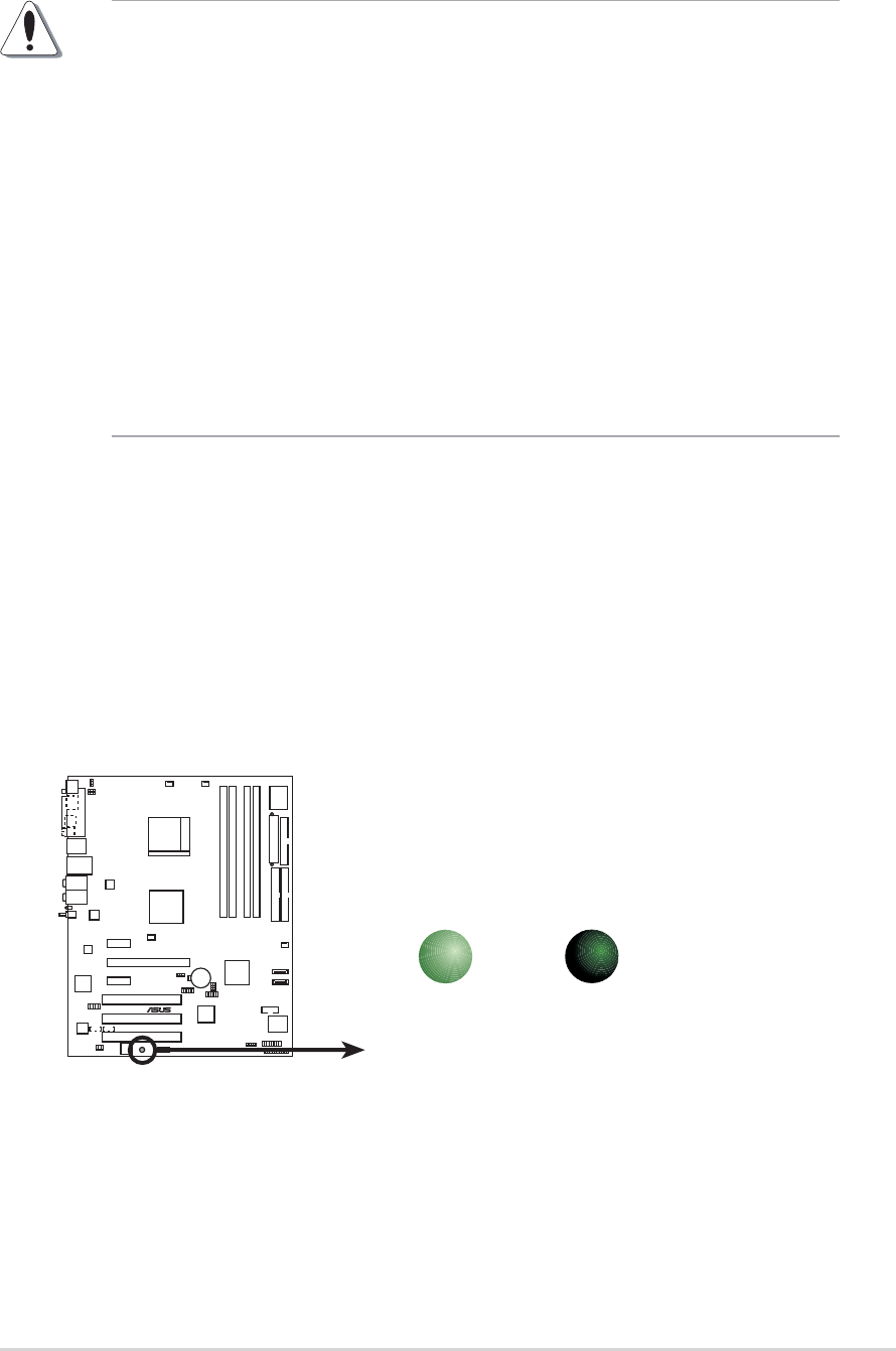
Onboard LEDOnboard LED
Onboard LEDOnboard LED
Onboard LED
The motherboard comes with a standby power LED that lights up to
indicate that the system is ON, in sleep mode, or in soft-off mode.
This is a reminder that you should shut down the system and unplug
the power cable before removing or plugging in any motherboard
component. The illustration below shows the location of the onboard
LED.
2.1 Before you proceed
Take note of the following precautions before you install motherboard
components or change any motherboard settings.
•Unplug the power cord from the wall socket before touching any
component.
• Use a grounded wrist strap or touch a safely grounded object or to
a metal object, such as the power supply case, before handling
components to avoid damaging them due to static electricity
•Hold components by the edges to avoid touching the ICs on them.
•Whenever you uninstall any component, place it on a grounded
antistatic pad or in the bag that came with the component.
•Before you install or remove any component, ensureBefore you install or remove any component, ensure
Before you install or remove any component, ensureBefore you install or remove any component, ensure
Before you install or remove any component, ensure
that the ATX power supply is switched off or thethat the ATX power supply is switched off or the
that the ATX power supply is switched off or thethat the ATX power supply is switched off or the
that the ATX power supply is switched off or the
power cord is detached from the power supply. power cord is detached from the power supply.
power cord is detached from the power supply. power cord is detached from the power supply.
power cord is detached from the power supply. Failure
to do so may cause severe damage to the motherboard, peripherals,
and/or components.
A8V-E
DELUXE
®
A8V-E DELUXE Onboard LED
SB_PWR
ON
Standby
Power
OFF
Powered
Off
2-22-2
2-22-2
2-2 Chapter 2: Hardware informationChapter 2: Hardware information
Chapter 2: Hardware informationChapter 2: Hardware information
Chapter 2: Hardware information
A8V-E
DELUXE
®
2.2 Motherboard overview
Before you install the motherboard, study the configuration of your chassis
to ensure that the motherboard fits into it.
Make sure to unplug the power cord before installing or removing the
motherboard. Failure to do so can cause you physical injury and damage
motherboard components.
Do not overtighten the screws! Doing so can damage the motherboard.
2.2.12.2.1
2.2.12.2.1
2.2.1 Placement directionPlacement direction
Placement directionPlacement direction
Placement direction
When installing the motherboard, make sure that you place it into the
chassis in the correct orientation. The edge with external ports goes to the
rear part of the chassis as indicated in the image below.
2.2.22.2.2
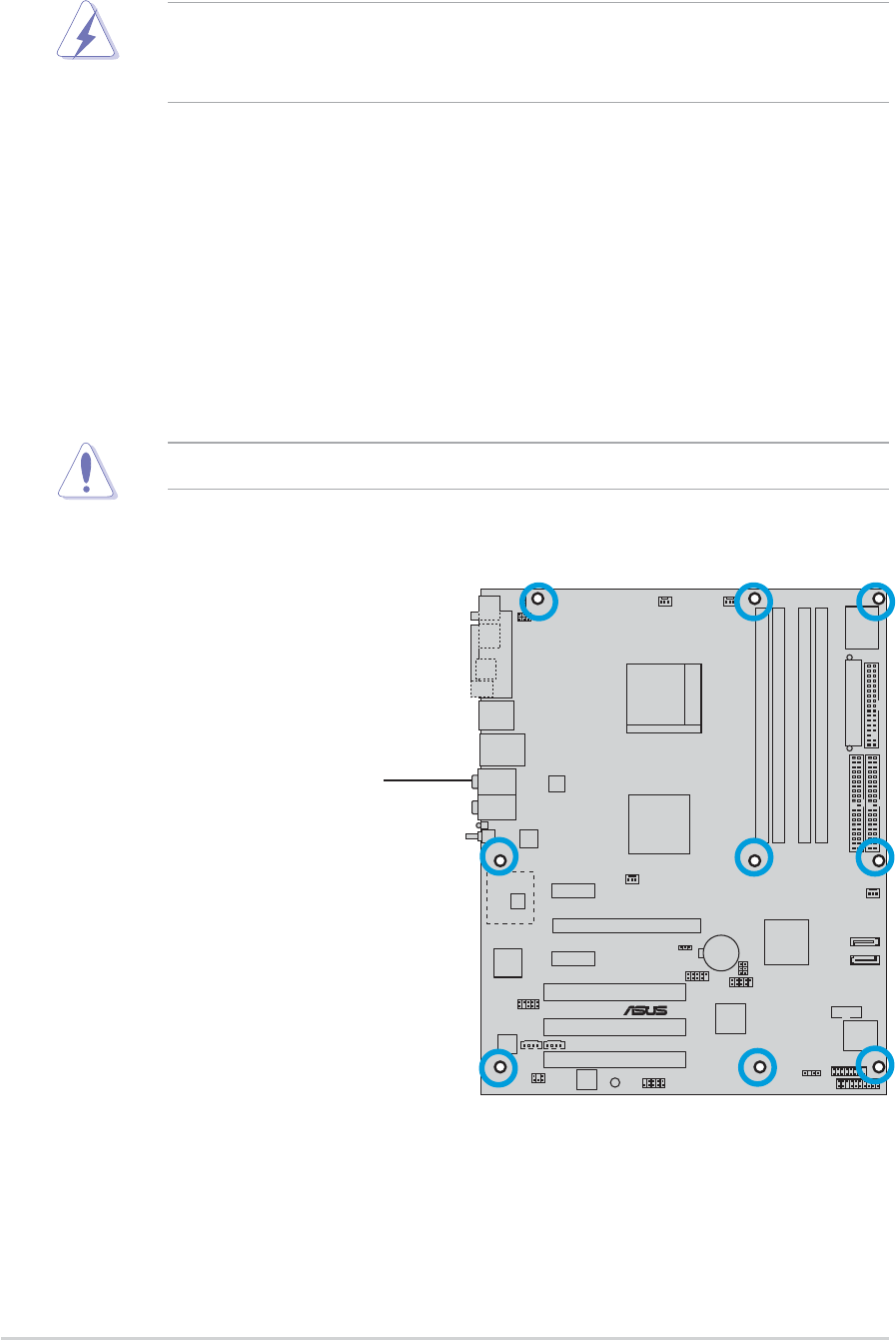
2.2.22.2.2
2.2.2 Screw holesScrew holes
Screw holesScrew holes
Screw holes
Place nine (9) screws into the holes indicated by circles to secure the
motherboard to the chassis.
Place this side towardsPlace this side towards
Place this side towardsPlace this side towards
Place this side towards
the rear of the chassisthe rear of the chassis
the rear of the chassisthe rear of the chassis
the rear of the chassis
ASUS A8V-E DeluxeASUS A8V-E Deluxe
ASUS A8V-E DeluxeASUS A8V-E Deluxe
ASUS A8V-E Deluxe 2-32-3
2-32-3
2-3
2.2.32.2.3
2.2.32.2.3
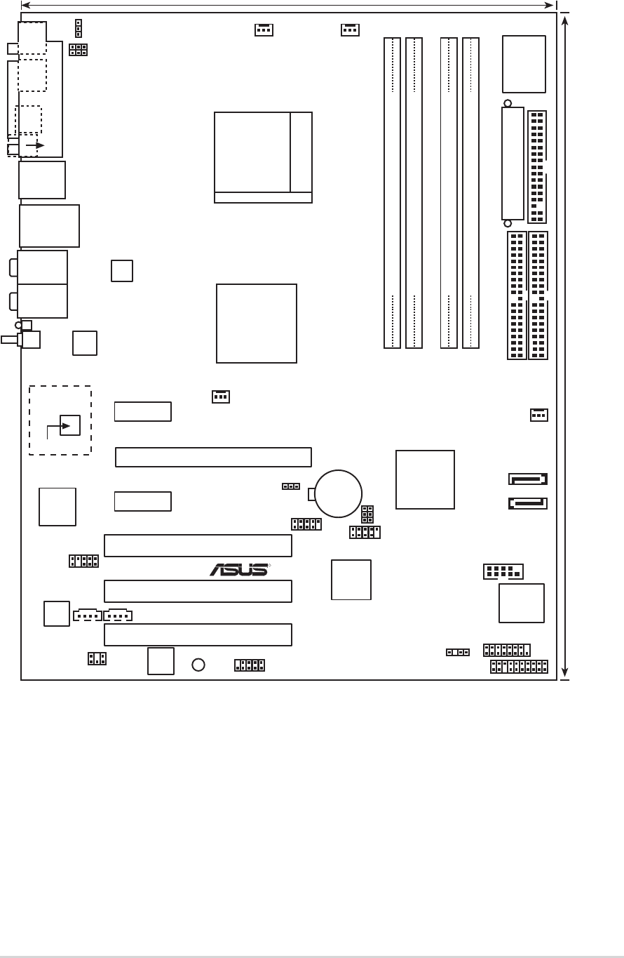
2.2.3 Motherboard layoutMotherboard layout
Motherboard layoutMotherboard layout
Motherboard layout
Bottom:Mic In
Center:Line Out
Top:Line In
PARALLEL PORT
MS1
KB1
SPDIF_O
SPDIF_O2
WL_LED
WL_ANT
Below:
Center/Subwoofer
Center:
Side Speaker Out
Top:Rear Speaker Out
PANEL
A8V-E
DELUXE
R
CR2032 3V
Lithium Cell
CMOS Power
CD
AUX
PCI1
FP_AUDIO
GAME
CHASSIS
CLRTC
PRI_IDE
SEC_IDE
EATXPWR
VIA
VT8237R
COM1
USB56
USBPW56
USBPW78
24.5cm (9.6in)
30.5cm (12.0in)
SATA1
VIA
K8T890
USB78
CPU_FAN
Socket 939
DDR DIMM_B1 (64 bit,184-pin module)
DDR DIMM_A1 (64 bit,184-pin module)
DDR DIMM_A2 (64 bit,184-pin module)
DDR DIMM_B2 (64 bit,184-pin module)
CHA_FAN2
LAN_USB34
F_USB12
PCI2
PCI3
PCIEX1_1
PCIEX1_2
PCIEX16
SPDIF
SB_PWR IE_1394_2
SATA2
PWR_FAN CHA_FAN1
KBPWR
USBPW12
USBPW34
ATX12V
FLOPPY
Super
I/O
ALC850
TI
TSB43AB22A
4Mb
BIOS
Speech
Controller
Marvell
88W8310
88W8000G
Marvell
88E8053
2-42-4
2-42-4
2-4 Chapter 2: Hardware informationChapter 2: Hardware information
Chapter 2: Hardware informationChapter 2: Hardware information
Chapter 2: Hardware information
2.2.42.2.4
2.2.42.2.4
2.2.4 Layout ContentsLayout Contents
Layout ContentsLayout Contents
Layout Contents
SlotsSlots
SlotsSlots
Slots PagePage
PagePage
Page
1. DDR DIMM slots 2-11
2. PCI slots 2-18
3. PCI Express x16 slot 2-18
4. PCI Express x1 slot 2-18
JumpersJumpers
JumpersJumpers
Jumpers PagePage
PagePage
Page
1. Clear RTC RAM (3-pin CLRTC) 2-19
2. USB Device wake-up (3-pin USBPW12, USBPW34, USBPW56, USBPW78) 2-19
3. Keyboard power (3-pin KBPWR) 2-19
Rear panel connectorsRear panel connectors
Rear panel connectorsRear panel connectors
Rear panel connectors PagePage
PagePage
Page
1. Parallel port 2-22
2. IEEE 1394 port 2-22
3. RJ-45 port 2-22
4. Rear Speaker Out port (gray) 2-22
5. Side Speaker Out port (black) 2-22
6. Line In port (light blue) 2-22
7. Line Out port (lime) 2-22
8. WiFi-g™ antenna port 2-23
9. Wireless LAN data transmission LED 2-23
10. Microphone port (pink) 2-23
11. Center/Subwoofer port (yellow orange) 2-23
12. USB 2.0 ports 3 and 4 2-23
13. USB 2.0 ports 1 and 2 2-23
14. Optical S/PDIF out port 2-23
15. Coaxial S/PDIF out port 2-23
16. PS/2 keyboard port (purple) 2-23
17. PS/2 mouse port (green) 2-23

ASUS A8V-E DeluxeASUS A8V-E Deluxe
ASUS A8V-E DeluxeASUS A8V-E Deluxe
ASUS A8V-E Deluxe 2-52-5
2-52-5
2-5
Internal connectorsInternal connectors
Internal connectorsInternal connectors
Internal connectors PagePage
PagePage
Page
1. Floppy disk drive connector (34-1 pin FLOPPY) 2-24
2. Primary IDE connector (40-1 pin PRI_IDE) 2-24
3. Secondary IDE connector (40-1 pin SEC_IDE) 2-24
4. Serial ATA connectors (7-pin SATA1, SATA2) 2-25
5. CPU fan connector (4-pin CPU_FAN) 2-26
6. Power fan connector (3-pin CHIP_FAN) 2-26
7. Chassis fan connector (3-pin CHA_FAN1) 2-26
8. Chassis fan 2 connector (3-pin CHA_FAN2) 2-26
9. Serial port connector (10-1 pin COM1) 2-27
10. USB headers (10-1 USB56, USB78) 2-27
11. ATX power connector (24-pin EATXPWR) 2-28
12. ATX 12V power connector (4-pin ATX12V) 2-28
13. Internal audio connector (4-pin CD, AUX) 2-29
14. GAME/MIDI connector (16-1 pin GAME) 2-29
15. Chassis intrusion connector (4-1 pin CHASSIS) 2-30
16. IEEE 1394 connector (10-1 pin IE1394_2) 2-30
17. Front panel audio connector (10-1 pin F_PANEL) 2-31
18. Digital audio connector (4-pin SPDIF) 2-31
19. System panel connectors (20-1 pin PANEL) 2-32
- System Power LED (Green 3-pin PLED)
- Hard Disk activity (Red 2-pin IDE_LED)
- System warning speaker (Orange 4-pin SPEAKER)
- Power/Soft-off button(Yellow 2-pin PWR)
- Reset switch (Blue 2-pin RESET)
2-62-6
2-62-6
2-6 Chapter 2: Hardware informationChapter 2: Hardware information
Chapter 2: Hardware informationChapter 2: Hardware information
Chapter 2: Hardware information
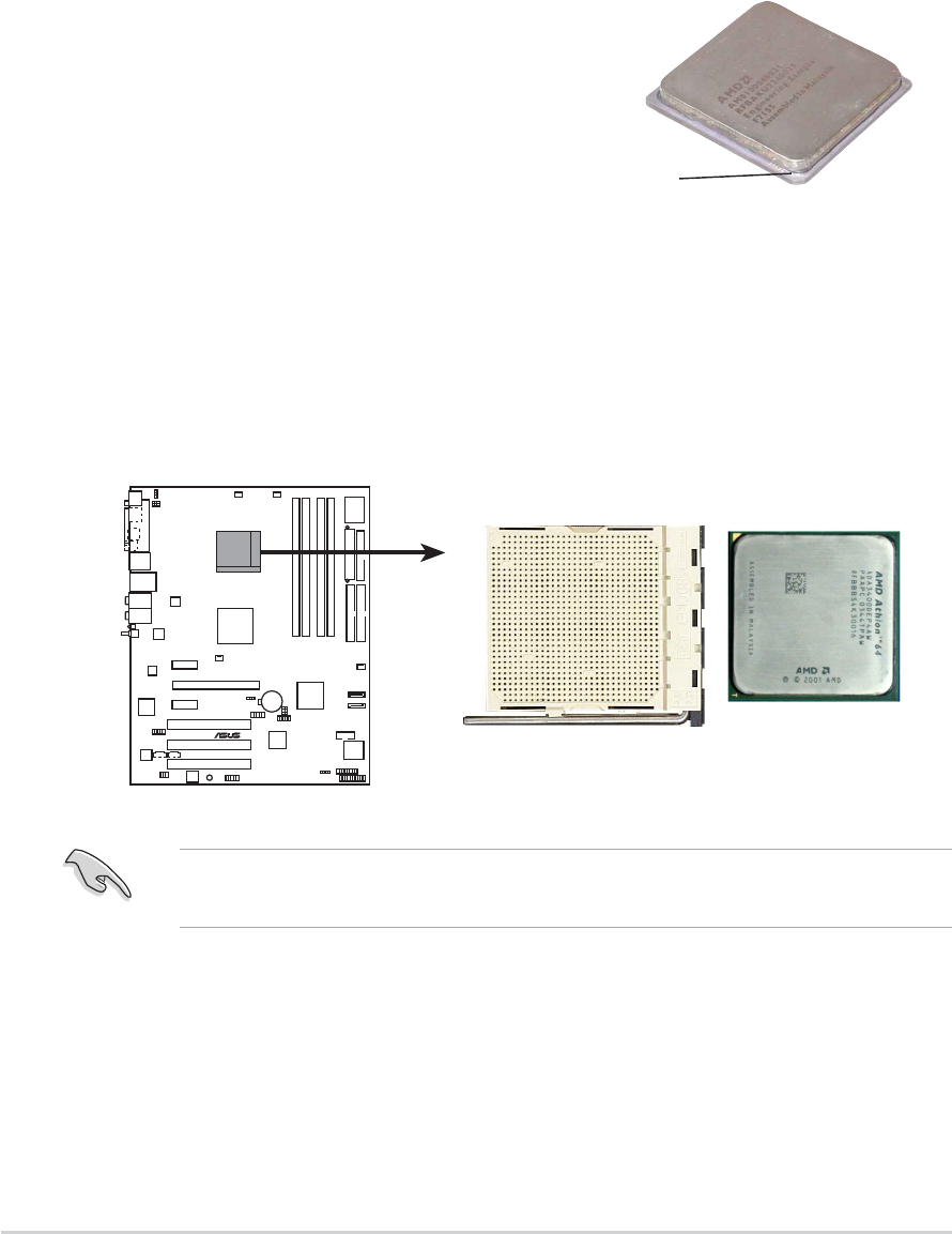
2.3.22.3.2
2.3.22.3.2
2.3.2 Installling the CPUInstallling the CPU
Installling the CPUInstallling the CPU
Installling the CPU
To install a CPU:
1. Locate the CPU socket on the motherboard.
Before installing the CPU, make sure that the socket box is facing
towards you and the load lever is on your left.
2.3 Central Processing Unit (CPU)
2.3.12.3.1
2.3.12.3.1
2.3.1 OverviewOverview
OverviewOverview
Overview
The motherboard comes with a surface mount 939-pin Zero Insertion Force
(ZIF) socket designed for the AMD Athlon™ 64FX or AMD Athlon 64™
processor.
The 128-bit-wide data paths of these processors can run applications
faster than processors with only 32-bit or 64-bit wide data paths.
Take note of the marked corner (with
gold triangle) on the CPU. This mark
should match a specific corner on the
socket to ensure correct installation.
Gold triangle
A8V-E
DELUXE
®
A8V-E DELUXE CPU Socket 939
ASUS A8V-E DeluxeASUS A8V-E Deluxe
ASUS A8V-E DeluxeASUS A8V-E Deluxe
ASUS A8V-E Deluxe 2-72-7
2-72-7
2-7
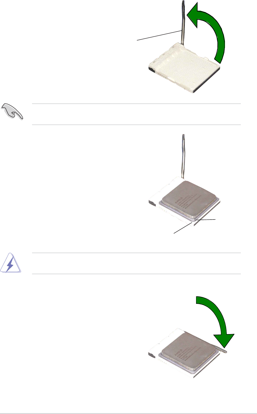
3. Position the CPU above the
socket such that the CPU corner
with the gold triangle matches
the socket corner with a small
triangle.
4. Carefully insert the CPU into the
socket until it fits in place.
2. Unlock the socket by pressing
the lever sideways, then lift it up
to a 90°-100° angle.
Make sure that the socket lever is lifted up to 90°-100° angle, otherwise
the CPU does not fit in completely.
The CPU fits only in one correct orientation. DO NOT force the CPU into
the socket to prevent bending the pins and damaging the CPU!
5. When the CPU is in place, push
down the socket lever to secure
the CPU. The lever clicks on the
side tab to indicate that it is
locked.
Gold triangleGold triangle
Gold triangleGold triangle
Gold triangle
Small triangleSmall triangle
Small triangleSmall triangle
Small triangle
Socket LeverSocket Lever
Socket LeverSocket Lever
Socket Lever
2-82-8
2-82-8
2-8 Chapter 2: Hardware informationChapter 2: Hardware information
Chapter 2: Hardware informationChapter 2: Hardware information
Chapter 2: Hardware information
2.3.32.3.3
2.3.32.3.3
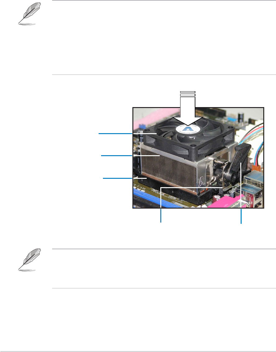
2.3.3 Installing the heatsink and fanInstalling the heatsink and fan
Installing the heatsink and fanInstalling the heatsink and fan
Installing the heatsink and fan
The AMD Athlon™ 64FX or AMD Athlon 64™ processor require a specially
designed heatsink and fan assembly to ensure optimum thermal condition
and performance.
Follow these steps to install the CPU heatsink and fan.
1. Place the heatsink on top of the installed CPU, making sure that the
heatsink fits properly on the retention module base.
Retention Module BaseRetention Module Base
Retention Module BaseRetention Module Base
Retention Module Base
CPU HeatsinkCPU Heatsink
CPU HeatsinkCPU Heatsink
CPU Heatsink
CPU FanCPU Fan
CPU FanCPU Fan
CPU Fan
Retention bracket lockRetention bracket lock
Retention bracket lockRetention bracket lock
Retention bracket lock
Retention bracketRetention bracket
Retention bracketRetention bracket
Retention bracket
•The retention module base is already installed on the motherboard
upon purchase.
•You do not have to remove the retention module base when
installing the CPU or installing other motherboard components.
•If you purchased a separate CPU heatsink and fan assembly, make
sure that a Thermal Interface Material is properly applied to the CPU
heatsink or CPU before you install the heatsink and fan assembly.
Your boxed CPU heatsink and fan assembly should come with installation
instructions for the CPU, heatsink, and the retention mechanism. If the
instructions in this section do not match the CPU documentation, follow
the latter.
ASUS A8V-E DeluxeASUS A8V-E Deluxe
ASUS A8V-E DeluxeASUS A8V-E Deluxe
ASUS A8V-E Deluxe 2-92-9
2-92-9
2-9
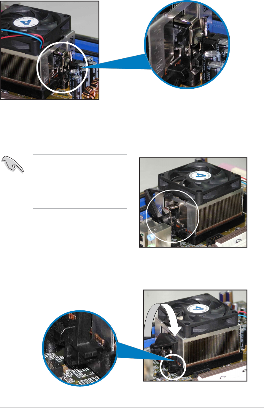
2. Attach one end of the retention bracket to the retention module
base.
3. Align the other end of the retention bracket (near the retention
bracket lock) to the retention module base. A clicking sound denotes
that the retention bracket is in place.
4. Push down the retention bracket lock on the retention mechanism to
secure the heatsink and fan to the module base.
Make sure that the fan and
heatsink assembly perfectly
fits the retention mechanism
module base, otherwise you
cannot snap the retention
bracket in place.
2-102-10
2-102-10
2-10 Chapter 2: Hardware informationChapter 2: Hardware information
Chapter 2: Hardware informationChapter 2: Hardware information
Chapter 2: Hardware information
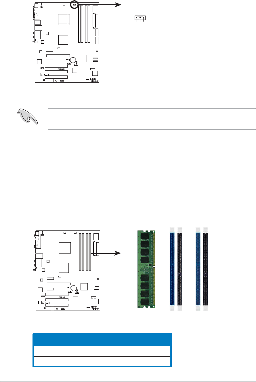
2.4 System memory
2.4.12.4.1
2.4.12.4.1
2.4.1 OverviewOverview
OverviewOverview
Overview
The motherboard comes with four 184-pin Double Data Rate (DDR) Dual
Inline Memory Modules (DIMM) sockets.
The following figure illustrates the location of the sockets:
ChannelChannel
ChannelChannel
Channel Sockets Sockets
Sockets Sockets
Sockets
Channel A DIMM_A1 and DIMM_A1
Channel B DIMM_B1 and DIMM_B2
3. When the fan and heatsink assembly is in place, connect the CPU fan
cable to the connector on the motherboard labeled CPU_FAN.
Do not forget to connect the CPU fan connector! Hardware monitoring
errors can occur if you fail to plug this connector.
A8V-E
DELUXE
®
A8V-E DELUXE CPU_Fan connector
CPU_FAN
GND
Rotation
+12V
A8V-E
DELUXE
®
A8V-E DELUXE 184-pin DDR DIMM sockets
DIMM_A1
DIMM_A2
DIMM_B1
DIMM_B2
ASUS A8V-E DeluxeASUS A8V-E Deluxe
ASUS A8V-E DeluxeASUS A8V-E Deluxe
ASUS A8V-E Deluxe 2-112-11
2-112-11
2-11
2.4.22.4.2
2.4.22.4.2
2.4.2 Memory ConfigurationsMemory Configurations
Memory ConfigurationsMemory Configurations
Memory Configurations
You may install 256 MB, 512 MB and 1 GB unbuffered ECC or non-ECC DDR
DIMMs into the DIMM sockets using the memory configurations in this
section.
•
For dual-channel configuration, the total size of memory module(s)
installed per channel must be the same for better performance
(DIMM_A1+DIMM_A2=DIMM_B1+DIMM_B2).
•
Always install DIMMs with the same CAS latency. For optimum
compatibility, it is recommended that you obtain memory modules
from the same vendor. Refer to the DDR400 Qualified Vendors List
on the next page for details.
•Due to chipset resource allocation, the system may detect less than
4 GB of system memory when you installed four 1 GB DDR memory
modules.
•Due to chipset limitation, DIMM modules with 128 Mb memory chips
or double-sided x16 memory chips are not supported in this
motherboard.
•Due to CPU limitation, install on Channel B slots for a single-channel
memory configuration.
DDR400 Qualified Vendors ListDDR400 Qualified Vendors List
DDR400 Qualified Vendors ListDDR400 Qualified Vendors List
DDR400 Qualified Vendors List
DIMM supportDIMM support
DIMM supportDIMM support
DIMM support
SizeSize
SizeSize
Size VendorVendor
VendorVendor
Vendor Model Model
Model Model
Model Brand Side(s) Brand Side(s)
Brand Side(s) Brand Side(s)
Brand Side(s) Component Component
Component Component
Component AA
AA
ABB
BB
BCC
CC
C
256MB KINGSTON KVR400X64C3A/256 Hynix SS HY5DU56822BT-D43 • • •
512MB KINGSTON KVR400X64C3A/512 Hynix DS HY5DU56822BT-D43 • •
256MB KINGSTON KVR400X72C3A/256 Mosel SS V58C2256804SAT5(ECC)
512MB KINGSTON KVR400X72C3A/512 Mosel DS V58C2256804SAT5(ECC) • •
256MB KINGSTON KVR400X64C3A/256 Infineon SS HYB25D256800BT-5B • • •
512MB KINGSTON KVR400X64C3A/512 Infineon DS HYB25D256809BT-5B •
256MB KINGSTON KVR400X64C3A/256 KINGSTON SS D3208DL2T-5 • • •
512MB KINGSTON KVR400X64C3A/512 KINGSTON DS D328DIB-50 •
1024MB KINGSTON HYB25D512800BE-5B N/A DS KVR400X64C3A/1G •
256MB SAMSUNG M381L3223ETM-CCC SAMSUNG SS K4H560838E-TCCC(ECC) • • •
512MB SAMSUNG M381L6423ETM-CCC SAMSUNG DS K4H560838E-TCCC(ECC) • • •
256MB SAMSUNG M368L3223ETM-CCC SAMSUNG SS K4H560838E-TCCC • • •
256MB SAMSUNG M368L3223FTN-CCC SAMSUNG SS K4H560838F-TCCC • • •
512MB SAMSUNG M368L6423FTN-CCC SAMSUNG DS K4H560838F-TCCC • •
512MB SAMSUNG M368L6523BTM-CCC SAMSUNG SS K4H510838B-TCCC • • •
256MB MICRON MT8VDDT3264AG-40BCB MICRON SS MT46V32M8TG-5BC • • •
512MB MICRON MT16VDDT6464AG-40BCB MICRON DS MT46V32M8TG-5BC • •
256MB Infineon HYS64D32300HU-5-C Infineon SS HYB25D256800CE-5C • • •
512MB Infineon HYS64D64320HU-5-C Infineon DS HYB25D256800CE-5C •
256MB CORSAIR CMX256A-3200C2PT Winbond SS W942508BH-5 •
512MB CORSAIR VS512MB400 VALUE seLecT DS VS32M8-5 •
1024MB CORSAIR TWINX2048-3200C2 N/A DS N/A •
256MB Hynix HYMD232645D8J-D43 Hynix SS HY5DU56822DT-D43 • • •
512MB Hynix HYMD264646D8J-D43 Hynix DS HY5DU56822DT-D43 • •
256MB GEIL GE2563200B GEIL SS GL3LC32G88TG-5A • • •
256MB GEIL GD3200-256V GEIL SS GLIL DDR 32M8 •
512MB GEIL GD3200-512V GEIL DS GLIL DDR 32M8 •
(continued on the next page)

2-122-12
2-122-12
2-12 Chapter 2: Hardware informationChapter 2: Hardware information
Chapter 2: Hardware informationChapter 2: Hardware information
Chapter 2: Hardware information
Visit the ASUS website (www.asus.com) for the latest DDR400 Qualified
Vendors List.
Side(s): SS - Side(s): SS -
Side(s): SS - Side(s): SS -
Side(s): SS - Single Sided DS -DS -
DS -DS -
DS - Double Sided
DIMM Support:DIMM Support:
DIMM Support:DIMM Support:
DIMM Support:
AA
AA
A- supports one module inserted into either slot, in a Single-channel memory
configuration.
BB
BB
B-supports on pair of modules inserted into either the yellow slots or the black
slots as one pair of Dual-channel memory configuration.
CC
CC
C-support for 4 modules inserted into the yellow and black slots as two pairs of
Dual-channel memory configuration.
DIMM supportDIMM support
DIMM supportDIMM support
DIMM support
SizeSize
SizeSize
Size VendorVendor
VendorVendor
Vendor Model Model
Model Model
Model Brand Side(s) Brand Side(s)
Brand Side(s) Brand Side(s)
Brand Side(s) Component Component
Component Component
Component AA
AA
ABB
BB
BCC
CC
C
256MB TwinMOS M2G9I08AIATT9F081AADT TwinMOS SS TMD7608F8E50D • • •
256MB TwinMOS M2G9I08A8ATT9F081AADT TwinMOS SS TMD7608F8E50D • •
512MB TwinMOS M2G9J16A8ATT9F081AADT TwinMOS DS TMD7608F8E50D •
256MB Transcend TS32MLD64V4F3 SAMSUNG SS K4H560838F-TCCC • • •
512MB Transcend TS64MLD64V4F3 SAMSUNG DS K4H560838F-TCCC •
1024MB Transcend TS128MLD64V4J SAMSUNG DS K4H510838B-TCCC •
512MB Transcend TS64MLD64V4F3 Mosel DS V58C2256804SAT5B •
256MB Transcend TS32MLD64V4F3 SAMSUNG SS K4H560838E-TCCC • • •
256MB Apacer 77.10636.33G Infineon SS HYB25D256800CE-5C • •
512MB Apacer 77.10736.33G Infineon DS HYB25D256800CE-5C •
256MB Apacer 77.10639.60G ProMOS SS V58C2256804SCT5B • •
512MB Apacer 77.10739.60G ProMOS DS V58C2256804SCT5B •
512MB A DATA MDOSS6F3H41Y0N1E0Z SAMSUNG DS K4H560838F-TCCC •
256MB A DATA MDOHY6F3G31Y0N1E0Z Hynix SS HY5DU56822CT-D43 • • •
256MB A DATA MDOAD5F3G31Y0D1E02 N/A SS ADD8608A8A-5B • •
512MB A DATA MDOAD5F3H41Y0D1E02 N/A DS ADD8608A8A-5B •
256MB Winbond W9425GCDB-5 Winbond SS W942508CH-5 •
512MB Winbond W9451GCDB-5 Winbond DS W942508CH-5 •
256MB KINGMAX MPXB62D-38KT3R N/A SS KDL388P4LA-50 • •
512MB KINGMAX MPXC22D-38KT3R N/A DS KDL388P4LA-50 •
512MB ATP AG64L64T8SQC4S SAMSUNG DS K4H560838D-TCC4 •
1024MB ATP AG28L64T8SMC4M MICRON DS MT46V64M4TG-5BC •
256MB NANYA NT256D64S88C0G-5T N/A SS NT5DS32M8CT-5T • • •
512MB NANYA NT512D64S8HC0G-5T N/A DS NT5DS32M8CT-5T •
256MB BRAIN POWER B6U808-256M-SAM-400 SAMSUNG SS K4H560838D-TCC4 •
256MB ProMOS V826632K24SCTG-D0 N/A SS V58C2256804SCT5B • •
512MB ProMOS V826664K24SCTG-D0 N/A DS V58C2256804SCT5B •
256MB Deutron A8C53T-5B1T PSC SS A2S56D30CTP • • •
512MB Deutron AL6D8C53T-5B1T PSC DS A2S56D30CTP •
256MB Novax 96M425653CE-40TB6 CEON SS C2S56D30TP-5 •
512MB Novax 96M451253CE-40TB6 CEON DS C2S56D30TP-5 •
ASUS A8V-E DeluxeASUS A8V-E Deluxe
ASUS A8V-E DeluxeASUS A8V-E Deluxe
ASUS A8V-E Deluxe 2-132-13
2-132-13
2-13
2.4.42.4.4
2.4.42.4.4
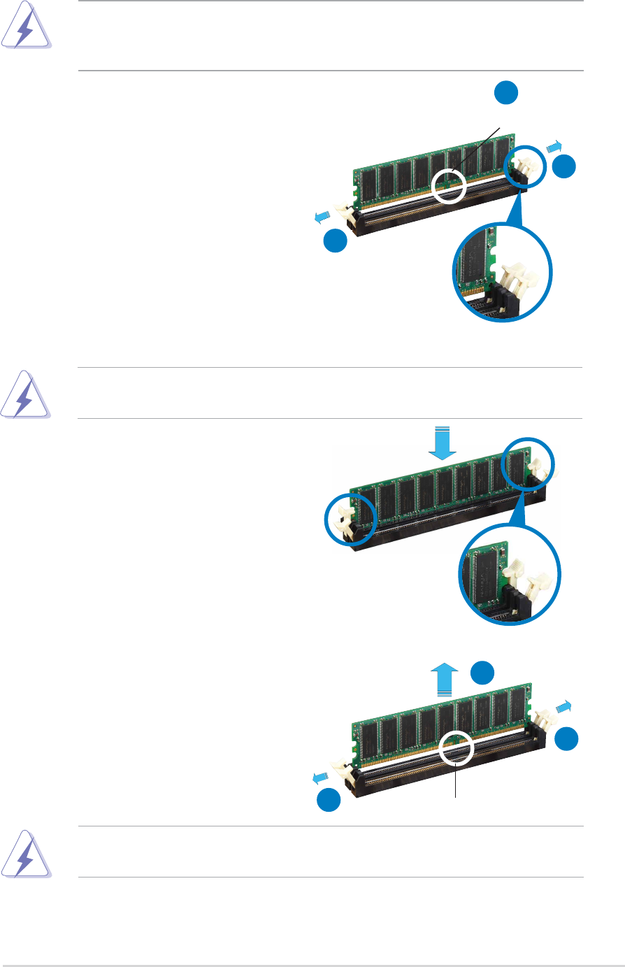
2.4.4 Removing a DIMMRemoving a DIMM
Removing a DIMMRemoving a DIMM
Removing a DIMM
Follow these steps to remove a DIMM.
1. Simultaneously press the
retaining clips outward to unlock
the DIMM.
2. Remove the DIMM from the socket.
Support the DIMM lightly with your fingers when pressing the retaining
clips. The DIMM might get damaged when it flips out with extra force.
2.4.32.4.3
2.4.32.4.3
2.4.3 Installing a DIMMInstalling a DIMM
Installing a DIMMInstalling a DIMM
Installing a DIMM
3. Firmly insert the DIMM into the
socket until the retaining clips
snap back in place and the DIMM
is properly seated.
1. Unlock a DIMM socket by
pressing the retaining clips
outward.
2. Align a DIMM on the socket such
that the notch on the DIMM
matches the break on the
socket.
Locked Retaining ClipLocked Retaining Clip
Locked Retaining ClipLocked Retaining Clip
Locked Retaining Clip
Make sure to unplug the power supply before adding or removing DIMMs
or other system components. Failure to do so may cause severe damage
to both the motherboard and the components.
A DDR DIMM is keyed with a notch so that it fits in only one direction.
DO NOT force a DIMM into a socket to avoid damaging the DIMM.
Unlocked retaining clipUnlocked retaining clip
Unlocked retaining clipUnlocked retaining clip
Unlocked retaining clip
DDR DIMM notchDDR DIMM notch
DDR DIMM notchDDR DIMM notch
DDR DIMM notch
1
2
1
DDR DIMM notchDDR DIMM notch
DDR DIMM notchDDR DIMM notch
DDR DIMM notch
1
2
1

2-142-14
2-142-14
2-14 Chapter 2: Hardware informationChapter 2: Hardware information
Chapter 2: Hardware informationChapter 2: Hardware information
Chapter 2: Hardware information
2.5 Expansion slots
In the future, you may need to install expansion cards. The following
sub-sections describe the slots and the expansion cards that they support.
2.5.12.5.1
2.5.12.5.1
2.5.1 Installing an expansion cardInstalling an expansion card
Installing an expansion cardInstalling an expansion card
Installing an expansion card
To install an expansion card:
1. Before installing the expansion card, read the documentation that
came with it and make the necessary hardware settings for the card.
2. Remove the system unit cover (if your motherboard is already
installed in a chassis).
3. Remove the bracket opposite the slot that you intend to use. Keep
the screw for later use.
4. Align the card connector with the slot and press firmly until the card is
completely seated on the slot.
5. Secure the card to the chassis with the screw you removed earlier.
6. Replace the system cover.
2.5.22.5.2
2.5.22.5.2
2.5.2 Configuring an expansion cardConfiguring an expansion card
Configuring an expansion cardConfiguring an expansion card
Configuring an expansion card
After installing the expansion card, configure the it by adjusting the
software settings.
1. Turn on the system and change the necessary BIOS settings, if any.
See Chapter 4 for information on BIOS setup.
2. Assign an IRQ to the card. Refer to the tables on the next page.
3. Install the software drivers for the expansion card.
Make sure to unplug the power cord before adding or removing
expansion cards. Failure to do so may cause you physical injury and
damage motherboard components.
ASUS A8V-E DeluxeASUS A8V-E Deluxe
ASUS A8V-E DeluxeASUS A8V-E Deluxe
ASUS A8V-E Deluxe 2-172-17
2-172-17
2-17
2.5.32.5.3
2.5.32.5.3
2.5.3 Interrupt assignmentsInterrupt assignments
Interrupt assignmentsInterrupt assignments
Interrupt assignments
Standard interrupt assignmentsStandard interrupt assignments
Standard interrupt assignmentsStandard interrupt assignments
Standard interrupt assignments
IRQIRQ
IRQIRQ
IRQ PriorityPriority
PriorityPriority
Priority Standard FunctionStandard Function
Standard FunctionStandard Function
Standard Function
01 System Timer
12 Keyboard Controller
2– Re-direct to IRQ#9
311 Communications Port (COM2)*
412 Communications Port (COM1)*
513 IRQ holder for PCI steering*
614 Floppy Disk Controller
715 Printer Port (LPT1)*
83 System CMOS/Real Time Clock
94 IRQ holder for PCI steering*
10 5 IRQ holder for PCI steering*
11 6 IRQ holder for PCI steering*
12 7 PS/2 Compatible Mouse Port*
13 8 Numeric Data Processor
14 9 Primary IDE Channel
15 10 Secondary IDE Channel
* These IRQs are usually available for ISA or PCI devices.
IRQ assignments for this motherboardIRQ assignments for this motherboard
IRQ assignments for this motherboardIRQ assignments for this motherboard
IRQ assignments for this motherboard
AA
AA
ABB
BB
BCC
CC
CDD
DD
DEE
EE
EFF
FF
FGG
GG
GHH
HH
H
PCI slot 1 shared — — — ————
PCI slot 2 — shared — — ————
PCI slot 3 — — shared — ————
PCI E x1 slot 1 shared — — — ————
PCI E x1 slot 2 shared — — — ————
PCI E x16 slot shared — — — ————
Onboard USB controller 1 shared — — — ————
Onboard USB controller 2 shared — — — ————
Onboard USB controller 3 — shared — — ————
Onboard USB controller 4 — shared — — ————
Onboard USB 2.0 controller — — shared — ————
Onboard LAN shared — — — ————
Onboard wireless LAN — shared — — ————
Onboard 1394a shared — — — ————
When using PCI cards on shared slots, ensure that the drivers support
“Share IRQ” or that the cards do not need IRQ assignments. Otherwise,
conflicts will arise between the two PCI groups, making the system
unstable and the card inoperable.
2-182-18
2-182-18
2-18 Chapter 2: Hardware informationChapter 2: Hardware information
Chapter 2: Hardware informationChapter 2: Hardware information
Chapter 2: Hardware information
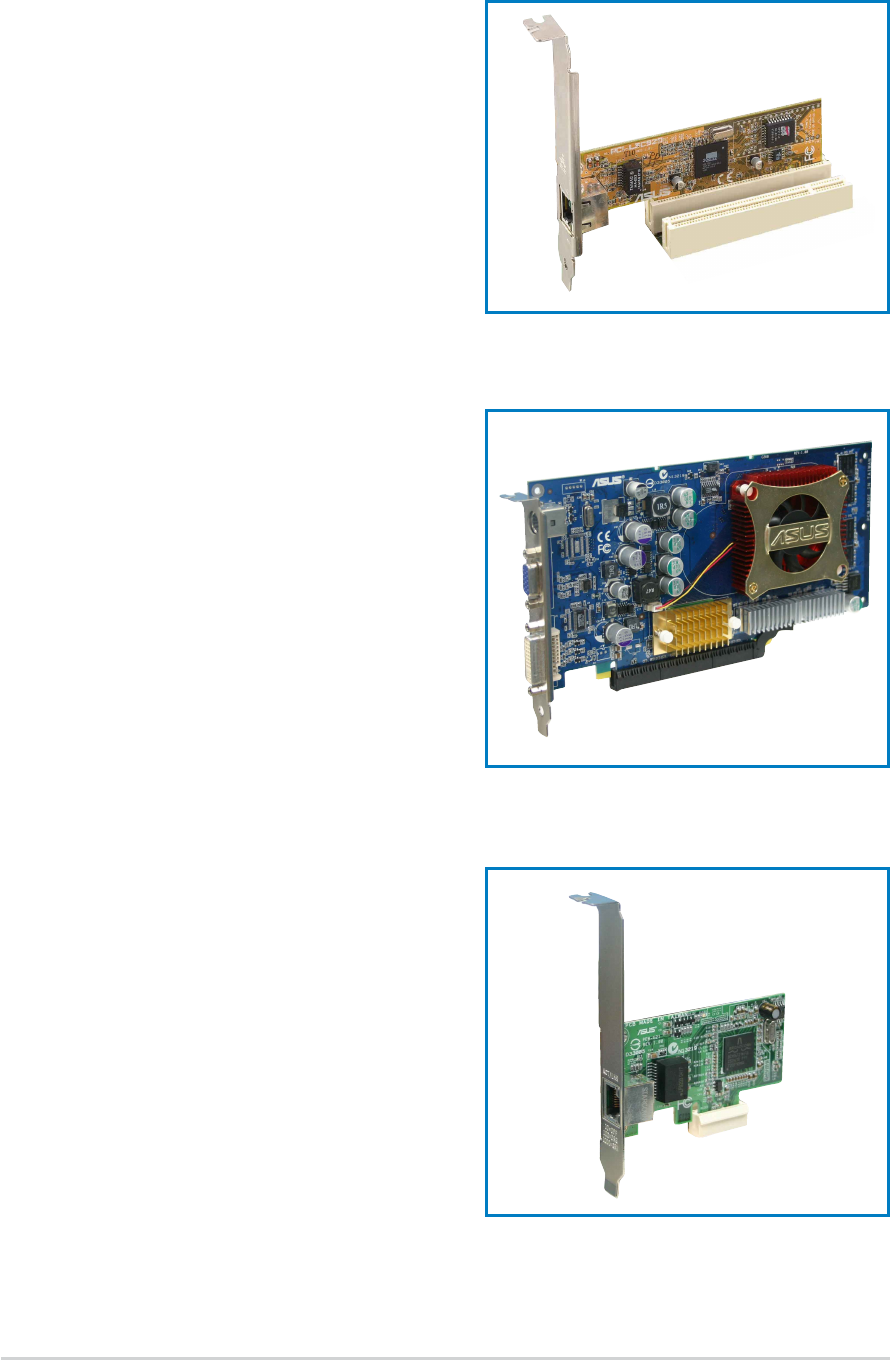
2.5.42.5.4
2.5.42.5.4
2.5.4 PCI slotsPCI slots
PCI slotsPCI slots
PCI slots
The PCI slots support cards such as a
LAN card, SCSI card, USB card, and
other cards that comply with PCI
specifications. The figure shows a
LAN card installed on a PCI slot.
2.5.52.5.5
2.5.52.5.5
2.5.5 PCI Express x16 slotPCI Express x16 slot
PCI Express x16 slotPCI Express x16 slot
PCI Express x16 slot
This motherboard supports PCI
Express x16 graphic cards that
comply with the PCI Express
specifications. The figure shows a
graphics card installed on the PCI
Express x16 slot.
2.5.62.5.6
2.5.62.5.6
2.5.6 PCI Express x1 slotPCI Express x1 slot
PCI Express x1 slotPCI Express x1 slot
PCI Express x1 slot
This motherboard supports PCI
Express x1 network cards, SCSI cards
and other cards that comply with the
PCI Express specifications. The figure
shows a network card installed on the
PCI Express x1 slot.
ASUS A8V-E DeluxeASUS A8V-E Deluxe
ASUS A8V-E DeluxeASUS A8V-E Deluxe
ASUS A8V-E Deluxe 2-192-19
2-192-19
2-19
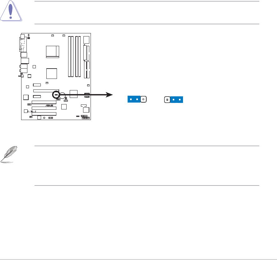
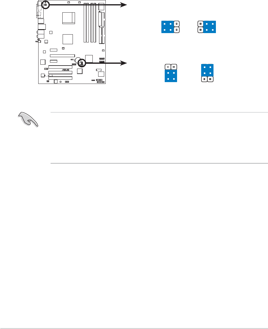
2.6 Jumpers
1.1.
1.1.
1. Clear RTC RAM (CLRTC)Clear RTC RAM (CLRTC)
Clear RTC RAM (CLRTC)Clear RTC RAM (CLRTC)
Clear RTC RAM (CLRTC)
This jumper allows you to clear the Real Time Clock (RTC) RAM in
CMOS. You can clear the CMOS memory of date, time, and system
setup parameters by erasing the CMOS RTC RAM data. The onboard
button cell battery powers the RAM data in CMOS, which include
system setup information such as system passwords.
To erase the RTC RAM:
1. Turn OFF the computer and unplug the power cord.
2. Remove the onboard battery.
3. Move the jumper cap from pins 1-2 (default) to pins 2-3. Keep the
cap on pins 2-3 for about 5~10 seconds, then move the cap back to
pins 1-2.
4. Re-install the battery.
5. Plug the power cord and turn ON the computer.
6. Hold down the <Del> key during the boot process and enter BIOS
setup to re-enter data.
Except when clearing the RTC RAM, never remove the cap on CLRTC
jumper default position. Removing the cap will cause system boot failure!
You do not need to clear the RTC when the system hangs due to
overclocking. For system failure due to overclocking, use the C.P.R. (CPU
Parameter Recall) feature. Shut down and reboot the system so the BIOS
can automatically reset parameter settings to default values.
12 23
A8V-E
DELUXE
®
A8V-E DELUXE Clear RTC RAM
CLRTC
Normal Clear CMOS
(Default)
2-202-20
2-202-20
2-20 Chapter 2: Hardware informationChapter 2: Hardware information
Chapter 2: Hardware informationChapter 2: Hardware information
Chapter 2: Hardware information
2.2.
2.2.
2. USB device wake-up (3-pin USBPW12, USBPW34,USB device wake-up (3-pin USBPW12, USBPW34,
USB device wake-up (3-pin USBPW12, USBPW34,USB device wake-up (3-pin USBPW12, USBPW34,
USB device wake-up (3-pin USBPW12, USBPW34,
USBPW56, USBPW78)USBPW56, USBPW78)
USBPW56, USBPW78)USBPW56, USBPW78)
USBPW56, USBPW78)
Set these jumpers to +5V to wake up the computer from S1 sleep
mode (CPU stopped, DRAM refreshed, system running in low power
mode) using the connected USB devices. Set to +5VSB to wake up
from S3 and S4 sleep modes (no power to CPU, DRAM in slow refresh,
power supply in reduced power mode).
The USBPWR12 and USBPWR34 jumpers are for the rear USB ports.
The USBPWR56 and USBPWR78 jumper is for the internal USB
connectors that you can connect to additional USB ports.
• The USB device wake-up feature requires a power supply that can
provide 500mA on the +5VSB lead for each USB port; otherwise,
the system would not power up.
•The total current consumed must NOT exceed the power supply
capability (+5VSB) whether under normal condition or in sleep mode.
3
2
3
2
21
A8V-E
DELUXE
®
A8V-E DELUXE USB device wake-up
+5V
(Default) +5VSB
USBPW78
USBPW56
+5V
(Default) +5VSB
USBPW34
USBPW12
1
2
ASUS A8V-E DeluxeASUS A8V-E Deluxe
ASUS A8V-E DeluxeASUS A8V-E Deluxe
ASUS A8V-E Deluxe 2-212-21
2-212-21
2-21
3.3.
3.3.
3. Keyboard power (3-pin KBPWR)Keyboard power (3-pin KBPWR)
Keyboard power (3-pin KBPWR)Keyboard power (3-pin KBPWR)
Keyboard power (3-pin KBPWR)
This jumper allows you to enable or disable the keyboard wake-up
feature. Set this jumper to pins 2-3 (+5VSB) if you wish to wake up
the computer when you press a key on the keyboard (the default is
the Space Bar). This feature requires an ATX power supply that can
supply at least 1A on the +5VSB lead, and a corresponding setting in
the BIOS.
A8V-E
DELUXE
®
A8V-E DELUXE Keyboard power setting
(Default)
+5V +5VSB
KBPWR
2
1
2
1
2-222-22
2-222-22
2-22 Chapter 2: Hardware informationChapter 2: Hardware information
Chapter 2: Hardware informationChapter 2: Hardware information
Chapter 2: Hardware information
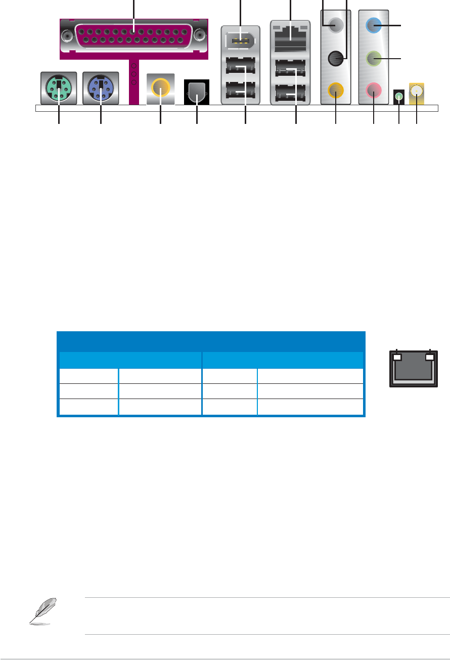
2.7 Connectors
2.7.12.7.1
2.7.12.7.1
2.7.1 Rear panel connectorsRear panel connectors
Rear panel connectorsRear panel connectors
Rear panel connectors
1.1.
1.1.
1. Parallel port.Parallel port.
Parallel port.Parallel port.
Parallel port. This 25-pin port connects a parallel printer, a scanner,
or other devices.
2.2.
2.2.
2. IEEE 1394a port.IEEE 1394a port.
IEEE 1394a port.IEEE 1394a port.
IEEE 1394a port. This 6-pin IEEE 1394 port provides high-speed
connectivity for audio/video devices, storage peripherals, PCs, or
portable devices.
3.3.
3.3.
3. LAN RJ-45 port.LAN RJ-45 port.
LAN RJ-45 port.LAN RJ-45 port.
LAN RJ-45 port. This port allows Gigabit connection to a Local
Area Network (LAN) through a network hub. Refer to the table below
for the LAN port LED indications.
SPEED
LED
ACT/LINK
LED
LAN port
LAN port LED indicationsLAN port LED indications
LAN port LED indicationsLAN port LED indications
LAN port LED indications
4.4.
4.4.
4. Rear Speaker Out port (gray).Rear Speaker Out port (gray).
Rear Speaker Out port (gray).Rear Speaker Out port (gray).
Rear Speaker Out port (gray). This port connects the rear
speakers on a 4-channel, 6-channel, or 8-channel audio configuration.
5.5.
5.5.
5. Side Speaker Out port (black).Side Speaker Out port (black).
Side Speaker Out port (black).Side Speaker Out port (black).
Side Speaker Out port (black). This port connects the side
speakers in an 8-channel audio configuration.
6.6.
6.6.
6. Line In port (light blue).Line In port (light blue).
Line In port (light blue).Line In port (light blue).
Line In port (light blue). This port connects the tape, CD, DVD
player, or other audio sources.
7.7.
7.7.
7. Line Out port (lime).Line Out port (lime).
Line Out port (lime).Line Out port (lime).
Line Out port (lime). This port connects a headphone or a
speaker. In 4-channel, 6-channel, and 8-channel configuration, the
function of this port becomes Front Speaker Out.
ACT/LINK LED ACT/LINK LED
ACT/LINK LED ACT/LINK LED
ACT/LINK LED SPEED LED SPEED LED
SPEED LED SPEED LED
SPEED LED
StatusStatus
StatusStatus
Status DescriptionDescription
DescriptionDescription
Description StatusStatus
StatusStatus
Status DescriptionDescription
DescriptionDescription
Description
OFF No link OFF 10 Mbps connection
GREEN Linked ORANGE 100 Mbps connection
BLINKING Data activity GREEN 1 Gbps connection
Refer to the audio configuration table on the next page for the function
of the audio ports in 2, 4, 6, or 8-channel configuration.
12
1 3
15
2
13
4
14
1617 11
5
6
10
7
89
ASUS A8V-E DeluxeASUS A8V-E Deluxe
ASUS A8V-E DeluxeASUS A8V-E Deluxe
ASUS A8V-E Deluxe 2-232-23
2-232-23
2-23
Wireless LAN LED indicationsWireless LAN LED indications
Wireless LAN LED indicationsWireless LAN LED indications
Wireless LAN LED indications
8.8.
8.8.
8. WiFi-g™ antenna port.WiFi-g™ antenna port.
WiFi-g™ antenna port.WiFi-g™ antenna port.
WiFi-g™ antenna port. This port connects to the optional dipolar
antenna for the onboard ASUS WiFi-g™ solution. (
Wireless Edition only
)
9.9.
9.9.
9. Wireless LAN data transmission LED. Wireless LAN data transmission LED.
Wireless LAN data transmission LED. Wireless LAN data transmission LED.
Wireless LAN data transmission LED. This green AIRAIR
AIRAIR
AIR LED
indicates the data transmission status of the onboard wireless LAN
adapter. Refer to the table below for the LED indications.
StatusStatus
StatusStatus
Status IndicationIndication
IndicationIndication
Indication
OnOn
OnOn
On The onboard WiFi-g™ is on but has no data activity.
OffOff
OffOff
Off The onboard WiFi-g™ card is off.
FlashingFlashing
FlashingFlashing
Flashing The onboard WiFi-g™ card is transmitting and/or receiving data.
12.12.
12.12.
12. USB 2.0 ports 3 and 4.USB 2.0 ports 3 and 4.
USB 2.0 ports 3 and 4.USB 2.0 ports 3 and 4.
USB 2.0 ports 3 and 4. These two 4-pin Universal Serial Bus
(USB) ports are available for connecting USB 2.0 devices.
13.13.
13.13.
13. USB 2.0 ports 1 and 2.USB 2.0 ports 1 and 2.
USB 2.0 ports 1 and 2.USB 2.0 ports 1 and 2.
USB 2.0 ports 1 and 2. These two 4-pin Universal Serial Bus
(USB) ports are available for connecting USB 2.0 devices.
14.14.
14.14.
14. Optical S/PDIF Out portOptical S/PDIF Out port
Optical S/PDIF Out portOptical S/PDIF Out port
Optical S/PDIF Out port. This port connects an external audio
output device via an optical S/PDIF cable.
15.15.
15.15.
15. Coaxial S/PDIF Out port.Coaxial S/PDIF Out port.
Coaxial S/PDIF Out port.Coaxial S/PDIF Out port.
Coaxial S/PDIF Out port. This port connects an external audio
output device via a coaxial S/PDIF cable.
16.16.
16.16.
16. PS/2 keyboard port (purple).PS/2 keyboard port (purple).
PS/2 keyboard port (purple).PS/2 keyboard port (purple).
PS/2 keyboard port (purple). This port is for a PS/2 keyboard.
17.17.
17.17.
17. PS/2 mouse port (green).PS/2 mouse port (green).
PS/2 mouse port (green).PS/2 mouse port (green).
PS/2 mouse port (green). This port is for a PS/2 mouse.
10.10.
10.10.
10. Microphone port (pink). Microphone port (pink).
Microphone port (pink). Microphone port (pink).
Microphone port (pink). This port connects a microphone.
11.11.
11.11.
11. Center/Subwoofer port (yellow orange).Center/Subwoofer port (yellow orange).
Center/Subwoofer port (yellow orange).Center/Subwoofer port (yellow orange).
Center/Subwoofer port (yellow orange). This port connects
the center/subwoofer speakers.
Audio 2, 4, 6, or 8-channel configurationAudio 2, 4, 6, or 8-channel configuration
Audio 2, 4, 6, or 8-channel configurationAudio 2, 4, 6, or 8-channel configuration
Audio 2, 4, 6, or 8-channel configuration
Light Blue Line In Line In Line In Line In
Lime Line Out Front Speaker Out Front Speaker Out Front Speaker Out
Pink Mic In Mic In Mic In Mic In
Gray • Rear Speaker Out Rear Speaker Out Rear Speaker Out
Black • • • Side Speaker Out
Yellow Orange • • Center/Subwoofer Center/Subwoofer
PortPort
PortPort
Port HeadsetHeadset
HeadsetHeadset
Headset 4-channel4-channel
4-channel4-channel
4-channel 6-channel6-channel
6-channel6-channel
6-channel 8-channel8-channel
8-channel8-channel
8-channel
2-channel2-channel
2-channel2-channel
2-channel
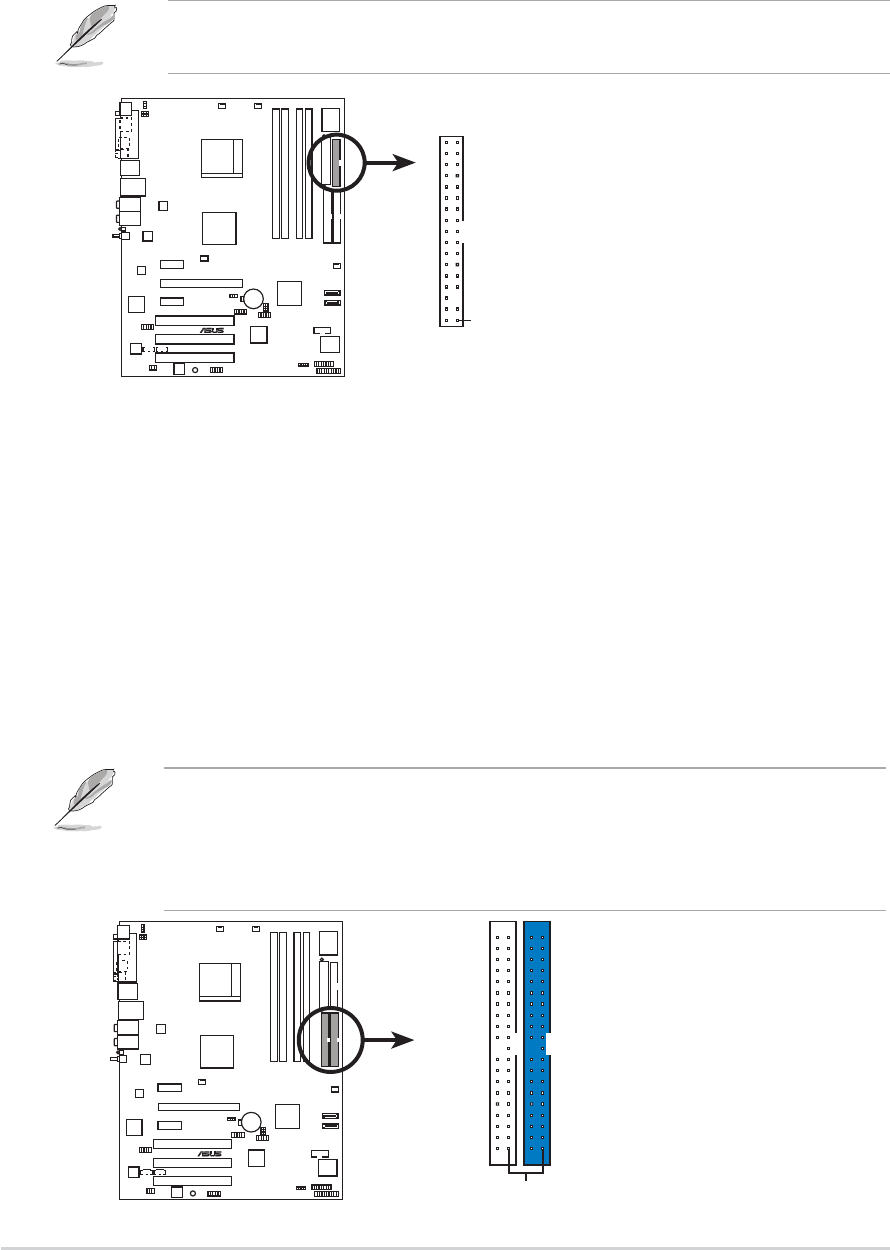
2-242-24
2-242-24
2-24 Chapter 2: Hardware informationChapter 2: Hardware information
Chapter 2: Hardware informationChapter 2: Hardware information
Chapter 2: Hardware information
2.2.
2.2.
2. IDE connectors (40-1 pin PRI_IDE, SEC_IDE)IDE connectors (40-1 pin PRI_IDE, SEC_IDE)
IDE connectors (40-1 pin PRI_IDE, SEC_IDE)IDE connectors (40-1 pin PRI_IDE, SEC_IDE)
IDE connectors (40-1 pin PRI_IDE, SEC_IDE)
These connectors are for Ultra DMA 133/100/66 signal cables. The
Ultra DMA 133/100/66 signal cable has three connectors: a blue
connector for the primary IDE connector on the motherboard, a black
connector for an Ultra DMA 133/100/66 IDE slave device (optical
drive/hard disk drive), and a gray connector for an Ultra DMA 133/
100/66 IDE master device (hard disk drive). If you install two hard disk
drives, you must configure the second drive as a slave device by setting
its jumper accordingly. Refer to the hard disk documentation for the
jumper settings.
2.7.22.7.2
2.7.22.7.2
2.7.2 Internal connectorsInternal connectors
Internal connectorsInternal connectors
Internal connectors
1.1.
1.1.
1. Floppy disk drive connector (34-1 pin FLOPPY)Floppy disk drive connector (34-1 pin FLOPPY)
Floppy disk drive connector (34-1 pin FLOPPY)Floppy disk drive connector (34-1 pin FLOPPY)
Floppy disk drive connector (34-1 pin FLOPPY)
This connector is for the provided floppy disk drive (FDD) signal cable.
Insert one end of the cable to this connector, then connect the other
end to the signal connector at the back of the floppy disk drive.
The Pin 5 on the connector is removed to prevent incorrect cable
connection when using an FDD cable with a covered Pin 5.
•The Pin 20 on the IDE connector is removed to match the covered
hole on the Ultra DMA cable connector. This prevents incorrect
insertion when you connect the IDE cable.
•Use the 80-conductor IDE cable for Ultra DMA 100/66 IDE devices.
A8V-E
DELUXE
®
A8V-E DELUXE Floppy disk drive connector
NOTE: Orient the red markings on
the floppy ribbon cable to PIN 1.
PIN 1
FLOPPY
A8V-E
DELUXE
®
A8V-E DELUXE IDE connectors
NOTE: Orient the red markings
(usually zigzag) on the IDE
ribbon cable to PIN 1.
PRI_IDE
PIN 1
SEC_IDE
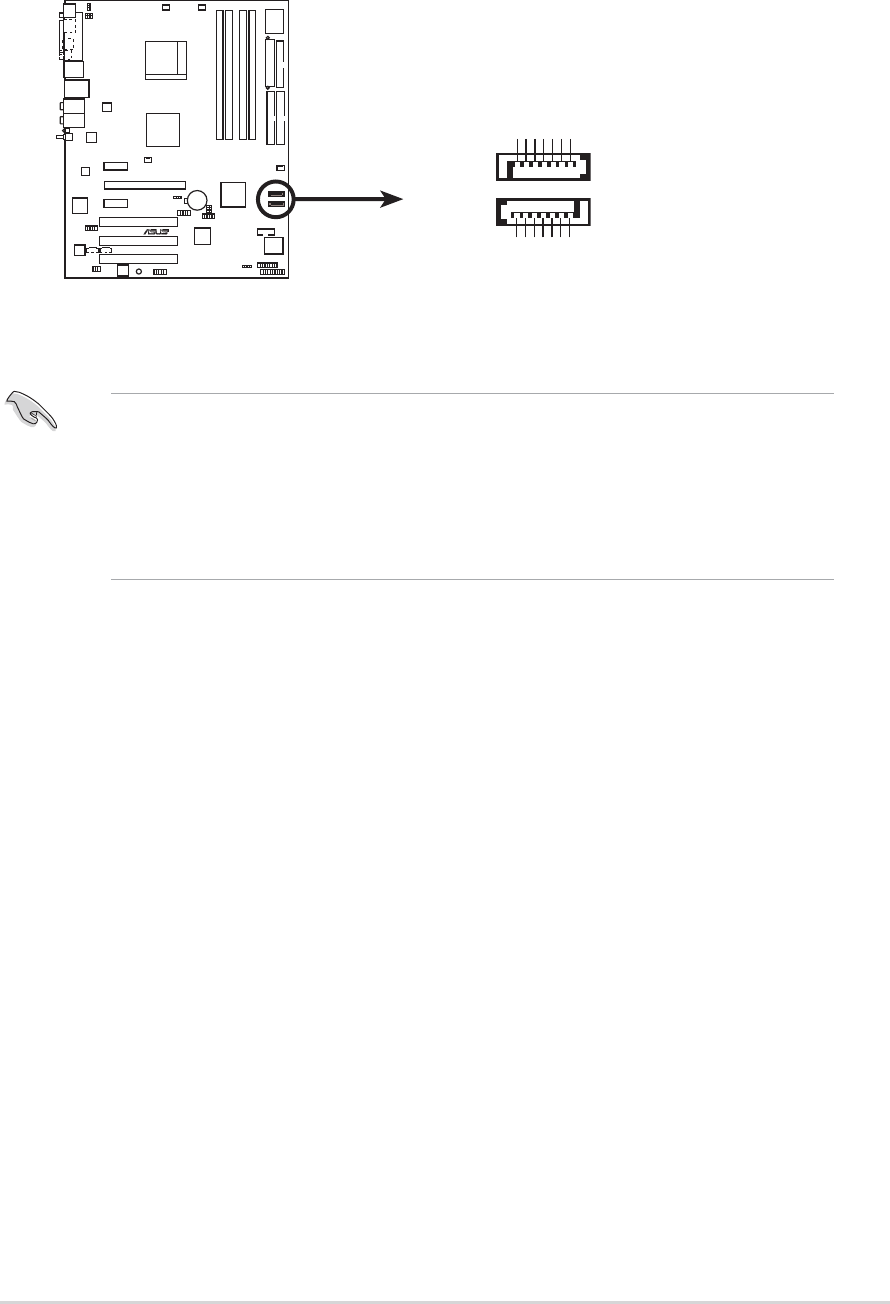
ASUS A8V-E DeluxeASUS A8V-E Deluxe
ASUS A8V-E DeluxeASUS A8V-E Deluxe
ASUS A8V-E Deluxe 2-252-25
2-252-25
2-25
3.3.
3.3.
3. Serial ATA connectors (7-pin SATA1, SATA2)Serial ATA connectors (7-pin SATA1, SATA2)
Serial ATA connectors (7-pin SATA1, SATA2)Serial ATA connectors (7-pin SATA1, SATA2)
Serial ATA connectors (7-pin SATA1, SATA2)
These connectors are for the Serial ATA signal cables for Serial ATA
hard disk drives.
Important notes on Serial ATAImportant notes on Serial ATA
Important notes on Serial ATAImportant notes on Serial ATA
Important notes on Serial ATA
•
The Serial ATA RAID feature (RAID 0, RAID 1) is available only if you
are using Windows
®
2000/XP.
•
Install the Windows
®
2000 Service Pack 4 or the Windows
®
XP
Service Pack1 when using Serial ATA.
A8V-E
DELUXE
R
A8V-E DELUXE SATA connectors
SATA1
GND
RSATA_TXP1
RSATA_TXN1
GND
RSATA_RXP1
RSATA_RXN1
GND
SATA2
GND
RSATA_TXP2
RSATA_TXN2
GND
RSATA_RXP2
RSATA_RXN2
GND
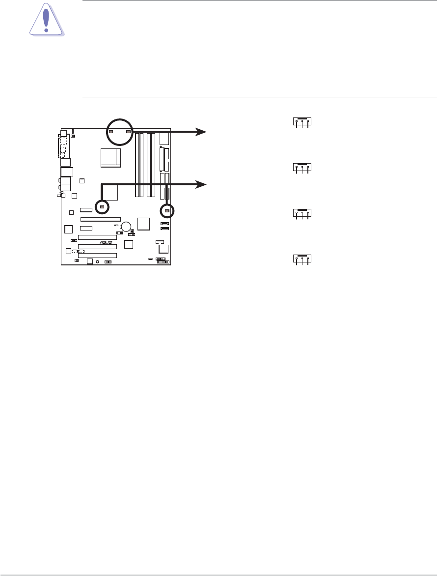
2-262-26
2-262-26
2-26 Chapter 2: Hardware informationChapter 2: Hardware information
Chapter 2: Hardware informationChapter 2: Hardware information
Chapter 2: Hardware information
4.4.
4.4.
4. CPU, Chassis, and Power fan connectorsCPU, Chassis, and Power fan connectors
CPU, Chassis, and Power fan connectorsCPU, Chassis, and Power fan connectors
CPU, Chassis, and Power fan connectors
(3-pin CPU_FAN, 3-pin CHA_FAN1, 3-pin CHIP_FAN,(3-pin CPU_FAN, 3-pin CHA_FAN1, 3-pin CHIP_FAN,
(3-pin CPU_FAN, 3-pin CHA_FAN1, 3-pin CHIP_FAN,(3-pin CPU_FAN, 3-pin CHA_FAN1, 3-pin CHIP_FAN,
(3-pin CPU_FAN, 3-pin CHA_FAN1, 3-pin CHIP_FAN,
CHA_FAN2)CHA_FAN2)
CHA_FAN2)CHA_FAN2)
CHA_FAN2)
The fan connectors support cooling fans of 350mA~2000mA (24 W
max.) or a total of 1A~3.48A (41.76 W max.) at +12V. Connect the
fan cables to the fan connectors on the motherboard, making sure that
the black wire of each cable matches the ground pin of the connector.
•Do not forget to connect the fan cables to the fan connectors. Lack
of sufficient air flow inside the system may damage the
motherboard components. These are not jumpers! DO NOT place
jumper caps on the fan connectors!
• The ASUS Q-Fan2 function is supported using the CPU Fan
(CPU_FAN) and Chassis Fan 1 (CHA_FAN1) connectors only.
A8V-E
DELUXE
R
A8V-E DELUXE Fan connectors
CPU_FAN
CHA_FAN1
CHIP_FAN
GND
Rotation
+12V
CHA_FAN2
GND
Rotation
+12V
GND
Rotation
+12V
GND
Rotation
+12V
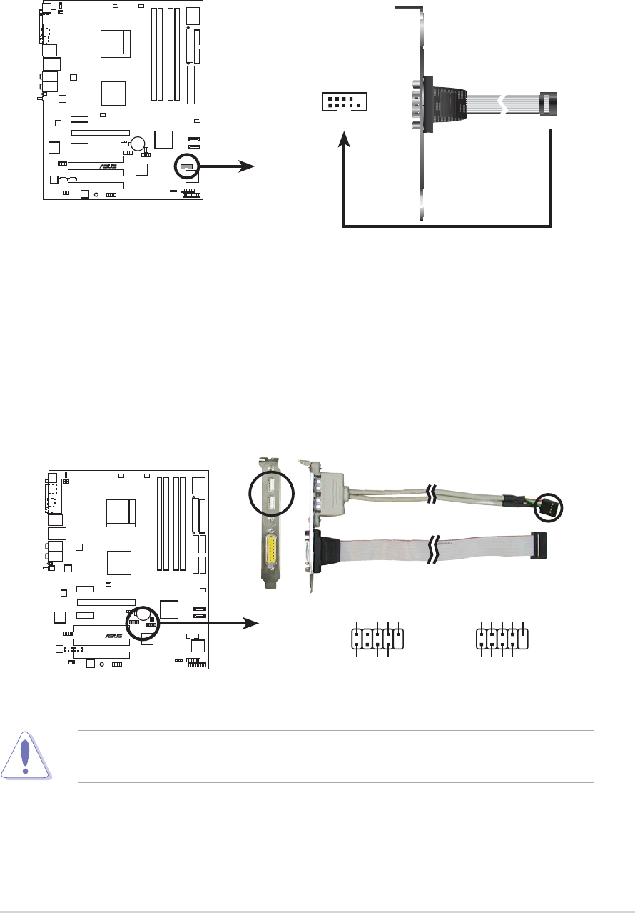
ASUS A8V-E DeluxeASUS A8V-E Deluxe
ASUS A8V-E DeluxeASUS A8V-E Deluxe
ASUS A8V-E Deluxe 2-272-27
2-272-27
2-27
5.5.
5.5.
5. Serial port connector (10-1 pin COM1)Serial port connector (10-1 pin COM1)
Serial port connector (10-1 pin COM1)Serial port connector (10-1 pin COM1)
Serial port connector (10-1 pin COM1)
This connector is for a serial (COM) port. Connect the serial port
module cable to this connector, then install the module to a slot
opening at the back of the system chassis.
Never connect a 1394 cable1394 cable
1394 cable1394 cable
1394 cable to the USB connectors. Doing so will
damage the motherboard!
6.6.
6.6.
6. USB connectors (10-1 pin USB56, USB78)USB connectors (10-1 pin USB56, USB78)
USB connectors (10-1 pin USB56, USB78)USB connectors (10-1 pin USB56, USB78)
USB connectors (10-1 pin USB56, USB78)
These connectors are for USB 2.0 ports. Connect the USB/GAME
module cable to any of these connectors, then install the module to a
slot opening at the back of the system chassis. These USB connectors
comply with USB 2.0 specification that supports up to 480 Mbps
connection speed.
A8V-E
DELUXE
®
A8V-E DELUXE COM port connector
PIN 1
COM1
A8V-E
DELUXE
®
A8V-E DELUXE USB 2.0 connectors
USB56
USB+5V
USB_P6-
USB_P6+
GND
NC
USB+5V
USB_P5-
USB_P5+
GND
1USB78
USB+5V
USB_P8-
USB_P8+
GND
NC
USB+5V
USB_P7-
USB_P7+
GND
1
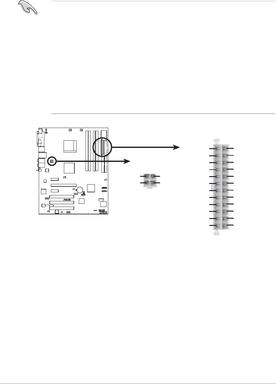
2-282-28
2-282-28
2-28 Chapter 2: Hardware informationChapter 2: Hardware information
Chapter 2: Hardware informationChapter 2: Hardware information
Chapter 2: Hardware information
7.7.
7.7.
7. ATX power connectors (24-pin EATXPWR,ATX power connectors (24-pin EATXPWR,
ATX power connectors (24-pin EATXPWR,ATX power connectors (24-pin EATXPWR,
ATX power connectors (24-pin EATXPWR, 4-pin ATX12V)4-pin ATX12V)
4-pin ATX12V)4-pin ATX12V)
4-pin ATX12V)
These connectors are for an ATX power supply plugs. The power
supply plugs are designed to fit these connectors in only one
orientation. Find the proper orientation and push down firmly until the
connectors completely fit.
•
Use of an ATX 12 V Specification 2.0-compliant power supply unit
(PSU) that provides a minimum power of 350 W is recommended
for a fully-configured system.
•
Do not forget to connect the 4-pin ATX +12 V power plug;
otherwise, the system will not boot up.
•Use of a PSU with a higher power output is recommended when
configuring a system with more power-consuming devices. The
system may become unstable or may not boot up if the power is
inadequate.
•You must install a PSU with a higher power rating if you intend to
install additional devices.
A8V-E
DELUXE
®
A8V-E DELUXE ATX power connectors
EATXPWR
ATX12V
+12V DC
GND
+12V DC
GND
+3 Volts
+3 Volts
Ground
+5 Volts
+5 Volts
Ground
Ground
Power OK
+5V Standby
+12 Volts
-5 Volts
+5 Volts
+3 Volts
-12 Volts
Ground
Ground
Ground
PSON#
Ground
+5 Volts
+12 Volts
+3 Volts
+5 Volts
Ground
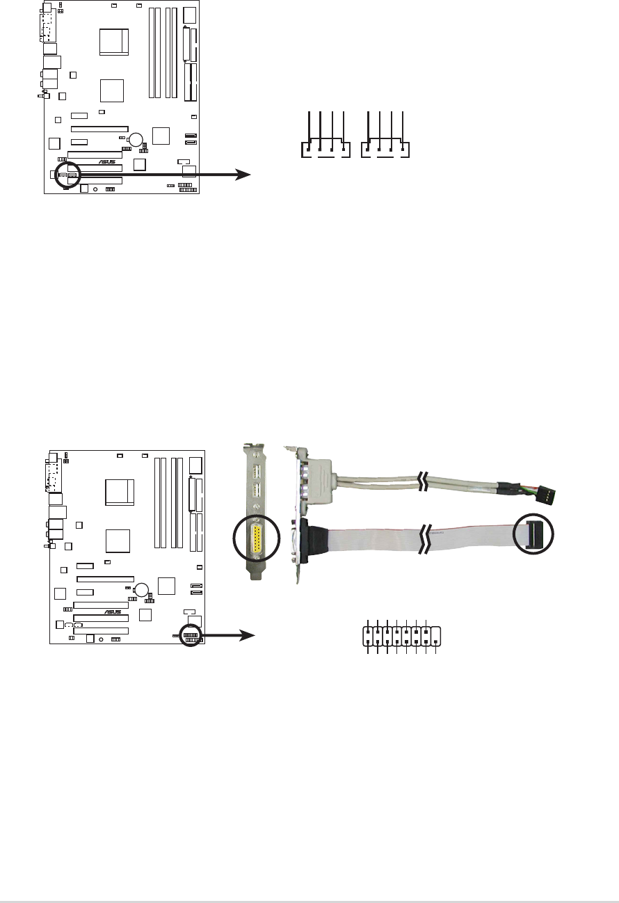
ASUS A8V-E DeluxeASUS A8V-E Deluxe
ASUS A8V-E DeluxeASUS A8V-E Deluxe
ASUS A8V-E Deluxe 2-292-29
2-292-29
2-29
8.8.
8.8.
8. Internal audio connectors (4-pin CD, AUX)Internal audio connectors (4-pin CD, AUX)
Internal audio connectors (4-pin CD, AUX)Internal audio connectors (4-pin CD, AUX)
Internal audio connectors (4-pin CD, AUX)
These connectors allow you to receive stereo audio input from sound
sources such as a CD-ROM, TV-tuner, or MPEG card.
9.9.
9.9.
9. GAME/MIDI port connector (16-1 pin GAME)GAME/MIDI port connector (16-1 pin GAME)
GAME/MIDI port connector (16-1 pin GAME)GAME/MIDI port connector (16-1 pin GAME)
GAME/MIDI port connector (16-1 pin GAME)
This connector is for a GAME/MIDI port. Connect the USB/GAME
module cable to this connector, then install the module to a slot
opening at the back of the system chassis. The GAME/MIDI port
connects a joystick or game pad for playing games, and MIDI devices
for playing or editing audio files.
A8V-E
DELUXE
®
A8V-E DELUXE Internal audio connectors
AUX
Right Audio Channel
Left Audio Channel
Ground
Ground
CD
Right Audio Channel
Left Audio Channel
Ground
Ground
A8V-E
DELUXE
®
A8V-E DELUXE Game connector
GAME
+5V +5V
J2B1
J2CX
MIDI_OUT
J2CY
J2B2
MIDI_IN
J1B1
J1CX
GND
GND
J1CY
J1B2
+5V
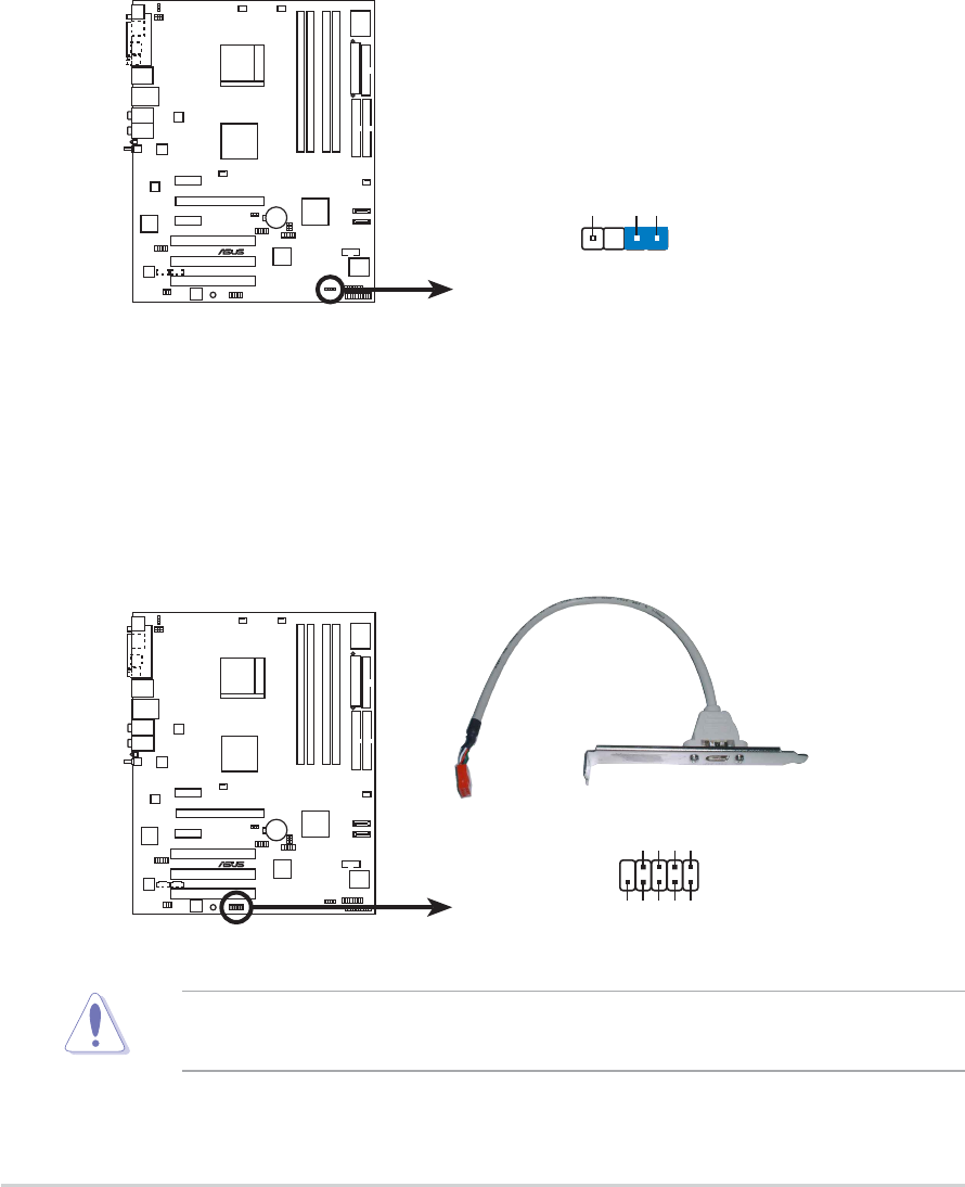
2-302-30
2-302-30
2-30 Chapter 2: Hardware informationChapter 2: Hardware information
Chapter 2: Hardware informationChapter 2: Hardware information
Chapter 2: Hardware information
10.10.
10.10.
10. Chassis intrusion connector (4-1 pin CHASSIS)Chassis intrusion connector (4-1 pin CHASSIS)
Chassis intrusion connector (4-1 pin CHASSIS)Chassis intrusion connector (4-1 pin CHASSIS)
Chassis intrusion connector (4-1 pin CHASSIS)
This connector is for a chassis-mounted intrusion detection sensor or
switch. Connect one end of the chassis intrusion sensor or switch
cable to this connector. The chassis intrusion sensor or switch sends a
high-level signal to this connector when a chassis component is
removed or replaced. The signal is then generated as a chassis
intrusion event.
By default, the pins labeled “Chassis Signal” and “Ground” are shorted
with a jumper cap. Remove the jumper caps only when you intend to
use the chassis intrusion detection feature.
A8V-E
DELUXE
®
A8V-E DELUXE Chassis alarm lead
CHASSIS
+5VSB_MB
Chassis Signal
GND
(Default)
Never connect a USB cable USB cable
USB cable USB cable
USB cable to the IEEE 1394a connectors. Doing so
will damage the motherboard!
11.11.
11.11.
11. IEEE 1394 connector (10-1 pin IE1394_2)IEEE 1394 connector (10-1 pin IE1394_2)
IEEE 1394 connector (10-1 pin IE1394_2)IEEE 1394 connector (10-1 pin IE1394_2)
IEEE 1394 connector (10-1 pin IE1394_2)
These connectors are for IEEE 1394a ports. Connect the IEEE 1394
module cable to this connector, then install the module to a slot
opening at the back of the system chassis.
A8V-E
DELUXE
®
A8V-E DELUXE IEEE 1394 connector
IE1394_2 1
GND
+12V
TPB2-
GND
TPA2-
+12V
TPB2+
GND
TPA2+
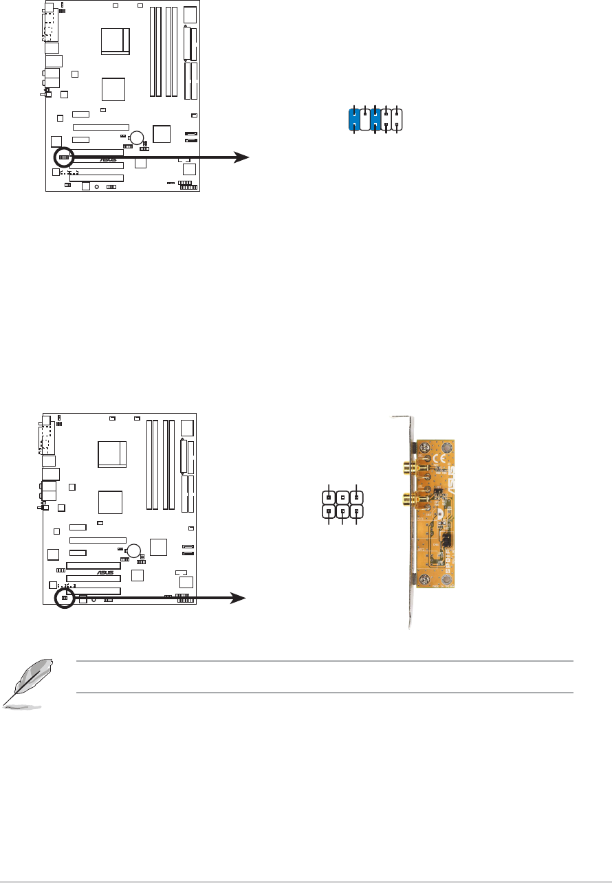
ASUS A8V-E DeluxeASUS A8V-E Deluxe
ASUS A8V-E DeluxeASUS A8V-E Deluxe
ASUS A8V-E Deluxe 2-312-31
2-312-31
2-31
A8V-E
DELUXE
®
A8V-E DELUXE Front panel audio connector
FP_AUDIO
BLINE_OUT_L
MIC2
Line out_R
Line out_L
BLINE_OUT_R
NC
MICPWR+5VA
AGND
12.12.
12.12.
12. Front panel audio connector (10-1 pin FP_AUDIO)Front panel audio connector (10-1 pin FP_AUDIO)
Front panel audio connector (10-1 pin FP_AUDIO)Front panel audio connector (10-1 pin FP_AUDIO)
Front panel audio connector (10-1 pin FP_AUDIO)
This connector is for a chassis-mounted front panel audio I/O module
that supports legacy AC ‘97 audio standard. Connect one end of the
front panel audio I/O module cable to this connector.
A8V-E
DELUXE
®
A8V-E DELUXE Digital audio connector
SPDIF
GND
+5V
SPDIF_IN
SPDIF_OUT
GND
1
13.13.
13.13.
13. Digital audio connector (4-1 pin SPDIF)Digital audio connector (4-1 pin SPDIF)
Digital audio connector (4-1 pin SPDIF)Digital audio connector (4-1 pin SPDIF)
Digital audio connector (4-1 pin SPDIF)
This connector is for an additional Sony/Philips Digital Interface
(S/PDIF) port(s). Connect the S/PDIF module cable to this connector,
then install the module to a slot opening at the back of the system
chassis.
The S/PDIF module is purchased separately.
2-322-32
2-322-32
2-32 Chapter 2: Hardware informationChapter 2: Hardware information
Chapter 2: Hardware informationChapter 2: Hardware information
Chapter 2: Hardware information
14.14.
14.14.
14. System panel connector (20-pin PANEL)System panel connector (20-pin PANEL)
System panel connector (20-pin PANEL)System panel connector (20-pin PANEL)
System panel connector (20-pin PANEL)
This connector supports several chassis-mounted functions.
The sytem panel connector is color-coded for easy connection. Refer to
the connector description below for details.
A8V-E
DELUXE
®
A8V-E DELUXE System panel connector
*
Requires an ATX power supply.
PANEL
PLED-
PWR
+5V
Speaker
Ground
RESET
Ground
Reset
Ground
Ground
PWR
PLED+
IDE_LED-
IDE_LED+
IDE LED
Ground
SMI
ExtSMI#
PLED SPEAKER
•
System power LED (Green 3-pin PLED)System power LED (Green 3-pin PLED)
System power LED (Green 3-pin PLED)System power LED (Green 3-pin PLED)
System power LED (Green 3-pin PLED)
This 3-pin connector is for the system power LED. Connect the
chassis power LED cable to this connector. The system power LED
lights up when you turn on the system power, and blinks when the
system is in sleep mode.
•
System warning speaker (Orange 4-pin SPEAKER)System warning speaker (Orange 4-pin SPEAKER)
System warning speaker (Orange 4-pin SPEAKER)System warning speaker (Orange 4-pin SPEAKER)
System warning speaker (Orange 4-pin SPEAKER)
This 4-pin connector is for the chassis-mounted system warning
speaker. The speaker allows you to hear system beeps and warnings.
•
Hard disk drive activity (Red 2-pin IDE_LED)Hard disk drive activity (Red 2-pin IDE_LED)
Hard disk drive activity (Red 2-pin IDE_LED)Hard disk drive activity (Red 2-pin IDE_LED)
Hard disk drive activity (Red 2-pin IDE_LED)
This 2-pin connector is for the HDD Activity LED. Connect the HDD
Activity LED cable to this connector. The IDE LED lights up or flashes
when data is read from or written to the HDD.
•
Power/Soft-off button (Yellow 2-pin PWR)Power/Soft-off button (Yellow 2-pin PWR)
Power/Soft-off button (Yellow 2-pin PWR)Power/Soft-off button (Yellow 2-pin PWR)
Power/Soft-off button (Yellow 2-pin PWR)
This connector is for the system power button. Pressing the power
button turns the system ON or puts the system in SLEEP or SOFT-OFF
mode depending on the BIOS settings. Pressing the power switch for
more than four seconds while the system is ON turns the system OFF.
•
Reset button (Blue 2-pin RESET)Reset button (Blue 2-pin RESET)
Reset button (Blue 2-pin RESET)Reset button (Blue 2-pin RESET)
Reset button (Blue 2-pin RESET)
This 2-pin connector is for the chassis-mounted reset button for
system reboot without turning off the system power.
3
Powering up
This chapter describes the power up
sequence, the vocal POST messages,
and ways of shutting down the
system.

ASUS A8V-E DeluxeASUS A8V-E Deluxe
ASUS A8V-E DeluxeASUS A8V-E Deluxe
ASUS A8V-E Deluxe
Chapter summary
3.1 Starting up for the first time................................................ 3-1
3.2 Powering off the computer .................................................. 3-2
3.3 ASUS POST Reporter™ .......................................................... 3-3

ASUS A8V-E DeluxeASUS A8V-E Deluxe
ASUS A8V-E DeluxeASUS A8V-E Deluxe
ASUS A8V-E Deluxe 3-13-1
3-13-1
3-1
3.1 Starting up for the first time
1. After making all the connections, replace the system case cover.
2. Be sure that all switches are off.
3. Connect the power cord to the power connector at the back of the
system chassis.
4. Connect the power cord to a power outlet that is equipped with a
surge protector.
5. Turn on the devices in the following order:
a. Monitor
b. External SCSI devices (starting with the last device on the chain)
c. System power
6. After applying power, the system power LED on the system front
panel case lights up. For systems withATX power supplies, the system
LED lights up when you press the ATX power button. If your monitor
complies with “green” standards or if it has a “power standby”
feature, the monitor LED may light up or switch between orange and
green after the system LED turns on.
The system then runs the power-on self tests or POST. While the
tests are running, the BIOS beeps (see BIOS beep codes table below)
or additional messages appear on the screen. If you do not see
anything within 30 seconds from the time you turned on the power,
the system may have failed a power-on test. Check the jumper
settings and connections or call your retailer for assistance.
7. At power on, hold down the <Delete> key to enter the BIOS Setup.
Follow the instructions in Chapter 4.

3-23-2
3-23-2
3-2 Chapter 3: Powering upChapter 3: Powering up
Chapter 3: Powering upChapter 3: Powering up
Chapter 3: Powering up
3.2 Powering off the computer
3.2.13.2.1
3.2.13.2.1
3.2.1 Using the OS shut down functionUsing the OS shut down function
Using the OS shut down functionUsing the OS shut down function
Using the OS shut down function
If you are using Windows
®
2000:
1. Click the Start Start
Start Start
Start button then click Shut Down...Shut Down...
Shut Down...Shut Down...
Shut Down...
2. Make sure that the Shut DownShut Down
Shut DownShut Down
Shut Down option button is selected, then click
the OK OK
OK OK
OK button to shut down the computer.
3. The power supply should turn off after Windows
®
shuts down.
If you are using Windows
®
XP:
1. Click the Start Start
Start Start
Start button then select Turn Off Computer.Turn Off Computer.
Turn Off Computer.Turn Off Computer.
Turn Off Computer.
2. Click the Turn Off Turn Off
Turn Off Turn Off
Turn Off button to shut down the computer.
3. The power supply should turn off after Windows
®
shuts down.
3.2.23.2.2
3.2.23.2.2
3.2.2 Using the dual function power switchUsing the dual function power switch
Using the dual function power switchUsing the dual function power switch
Using the dual function power switch
While the system is ON, pressing the power switch for less than four
seconds puts the system to sleep mode or to soft-off mode, depending on
the BIOS setting. Pressing the power switch for more than four seconds
lets the system enter the soft-off mode regardless of the BIOS setting.
Refer to section “4.5 Power Menu” in Chapter 4 for details.
ASUS A8V-E DeluxeASUS A8V-E Deluxe
ASUS A8V-E DeluxeASUS A8V-E Deluxe
ASUS A8V-E Deluxe 3-33-3
3-33-3
3-3
3.3 ASUS POST Reporter™
This motherboard includes the Winbond speech controller to support a
special feature called the ASUS POST Reporter™. This feature lets you hear
vocal messages during POST that alerts you of system events and boot
status. In case of a boot failure, you will hear the specific cause of the
problem.
These POST messages are customizable using the Winbond Voice Editor
software that came with your package. You can record your own messages
to replace the default messages.
3.3.13.3.1
3.3.13.3.1
3.3.1 Vocal POST messagesVocal POST messages
Vocal POST messagesVocal POST messages
Vocal POST messages
Following is a list of the default POST messages and the corresponding
actions you can take:
POST MessagePOST Message
POST MessagePOST Message
POST Message ActionAction
ActionAction
Action
No CPU installed
•
Install a supported processor to the
CPU socket. See section “2.3 Central
Processing Unit (CPU)” for details.
System failed CPU test
•
Check the CPU if properly installed.
•
Call ASUS technical support for
assistance. See the ASUS contact
information on the inside front cover
of this user guide.
System failed memory test
•
Install supported DDR2 DIMMs into the
memory sockets.
•
Check if the DIMMs on the DIMM
sockets are properly installed.
•
Make sure that your DIMMs are not
defective.
•
Refer to section “2.4 System memory”
for instructions on installing a DIMM.
System failed VGA test
•
Install a PCI graphics card into one of
the PCI slots, or a PCI Express AGP
card into the PCI Express x16 slot.
•
Make sure that your graphics card is
not defective.
System failed due to CPU
•
Check your CPU overclocking settings
in the BIOS setup and restore the
default CPU parameters.
No keyboard detected
•
Check if your keyboard is properly
connected to the purple PS/2
connector on the rear panel.
•See section “2.7.1 Rear panel
connectors” for the location of the
connector.
No IDE hard disk detected • Make sure you have connected an IDE
hard disk drive to one of the IDE
connectors on the motherboard.
3-43-4
3-43-4
3-4 Chapter 3: Powering upChapter 3: Powering up
Chapter 3: Powering upChapter 3: Powering up
Chapter 3: Powering up
POST MessagePOST Message
POST MessagePOST Message
POST Message ActionAction
ActionAction
Action
CPU temperature too high
•
Check if the CPU fan is working
properly.
CPU fan failed
•
Check the CPU fan and make sure it
turns on after you apply power to the
system.
•
Make sure that your CPU fan supports
the fan speed detection function.
CPU voltage out of range
•
Check your power supply and make
sure it is not defective.
•
Call ASUS technical support for
assistance. See the “ASUS contact
information” on the inside front cover
of this user guide.
Computer now booting from operating • No action required
system
You can enable or disable the ASUS POST Reporter™ in the SpeechSpeech
SpeechSpeech
Speech
Configuration Configuration
Configuration Configuration
Configuration option in the BIOS setup. See section 4.4.9 for details.
ASUS A8V-E DeluxeASUS A8V-E Deluxe
ASUS A8V-E DeluxeASUS A8V-E Deluxe
ASUS A8V-E Deluxe 3-53-5
3-53-5
3-5
3.3.23.3.2
3.3.23.3.2
3.3.2 Winbond Voice EditorWinbond Voice Editor
Winbond Voice EditorWinbond Voice Editor
Winbond Voice Editor
The Winbond Voice Editor software allows you to customize the vocal
POST messages. You can install this application from the support CD.
Launching the Voice EditorLaunching the Voice Editor
Launching the Voice EditorLaunching the Voice Editor
Launching the Voice Editor
You can launch the program from the Windows
®
desktop by clicking
StartStart
StartStart
Start > All Programs > Winbond Voice Editor > Voice Editor> All Programs > Winbond Voice Editor > Voice Editor
> All Programs > Winbond Voice Editor > Voice Editor> All Programs > Winbond Voice Editor > Voice Editor
> All Programs > Winbond Voice Editor > Voice Editor.
The Winbond Voice Editor screen appears.
Playing the default wave filesPlaying the default wave files
Playing the default wave filesPlaying the default wave files
Playing the default wave files
To play the default wave files, simply click on a POST event on the left side
of the screen, then click the Play button.
Default MessagesDefault Messages
Default MessagesDefault Messages
Default Messages
POST EventsPOST Events
POST EventsPOST Events
POST Events
To avoid conflicts, do not run the Winbond Voice Editor while running
the ASUS PC Probe application.
The default language setting is English.
3-63-6
3-63-6
3-6 Chapter 3: Powering upChapter 3: Powering up
Chapter 3: Powering upChapter 3: Powering up
Chapter 3: Powering up
3. Click the Write Write
Write Write
Write button from the Voice Editor main window to update
the EEPROM.
4. Click Yes Yes
Yes Yes
Yes to confirm.
Changing the default languageChanging the default language
Changing the default languageChanging the default language
Changing the default language
To change the default language:
1. Click the LoadLoad
LoadLoad
Load button from the
Voice Editor main window. A
window with the available
languages appears.
2. Select your desired language,
then click OpenOpen
OpenOpen
Open.
The event messages for the
language you selected appear
on the Voice Editor main
window.
Not all events on some languages have a corresponding message due to
file size constraints.
The next time you boot your computer, the ASUS Post Reporter announces
the messages in the selected language.
ASUS A8V-E DeluxeASUS A8V-E Deluxe
ASUS A8V-E DeluxeASUS A8V-E Deluxe
ASUS A8V-E Deluxe 3-73-7
3-73-7
3-7
Customizing your POST messagesCustomizing your POST messages
Customizing your POST messagesCustomizing your POST messages
Customizing your POST messages
The Voice Editor application allows you to record your own POST messages
if your language is not supported or if you wish to to replace the
pre-installed wave files.
To customize your POST messages.
1. Launch the Voice Editor application and note the list of POST events
on the leftmost column of the screen.
2. Prepare your message for each event.
3. Use a recording software (e.g. Windows
®
Recorder) to record your
messages, then save the messages as wave files (.WAV).
4. From the Voice Editor screen,
click the Add Add
Add Add
Add button to display
the Add Wave File Add Wave File
Add Wave File Add Wave File
Add Wave File window.
5. Copy the wave files that you
recorded to the database, then
close the window when done.
•The total compressed size for all the wave files must not exceed
1Mbit, so keep your messages as short as possible.
•To keep file sizes small, save your files at a low quality. For example,
use 8-bit, mono quality at 22Khz sampling rate.
•Create a separate folder for your wave files so you can locate them
easily.
3-83-8
3-83-8
3-8 Chapter 3: Powering upChapter 3: Powering up
Chapter 3: Powering upChapter 3: Powering up
Chapter 3: Powering up
If you receive an error message telling you that the files exceed the total
allowable size, do any or all of the following:
•
Shorten your messages.
•
Save the wave files at a lower quality
•
Do not include seldom-used events like FDD Detection, IDE HDD
Detection, etc.
6. Select a POST event on the
Voice Editor main window, then
click the Edit Edit
Edit Edit
Edit button. The
Event Sound EditorEvent Sound Editor
Event Sound EditorEvent Sound Editor
Event Sound Editor window
appears.
7. Locate and select your wave file
for the event, then click on the
arrow opposite Voice1. The file
you select appears on the space
next to it.
8. Click OK OK
OK OK
OK to return to the Voice
Editor main window.
9. Do steps 6 to 8 for the other
events.
10. When done, click SaveSave
SaveSave
Save. A
window appears prompting you
to save your configuration.
11. Type a file name with an .flh.flh
.flh.flh
.flh
extension, then click Save.
12. Click the Write Write
Write Write
Write button to
compress the file and copy into
the EEPROM.
13. Click Yes Yes
Yes Yes
Yes on the confirmation
window that appears.