ASUSTeK Computer MWOM4LA MOTHERBOARD User Manual FRONT A8V E Deluxe P65
ASUSTeK Computer Inc MOTHERBOARD FRONT A8V E Deluxe P65
Contents
- 1. users manual
- 2. USERS MANUAL 1
- 3. USERS MANUAL 2
USERS MANUAL 2
4
BIOS setup
This chapter tells how to change
the system settings through the BIOS
Setup menus. Detailed descriptions
of the BIOS parameters are also
provided.

ASUS A8V-E DeluxeASUS A8V-E Deluxe
ASUS A8V-E DeluxeASUS A8V-E Deluxe
ASUS A8V-E Deluxe
Chapter summary
4.1 Managing and updating your BIOS ........................................ 4-1
4.2 BIOS setup program ........................................................... 4-11
4.3 Main menu .......................................................................... 4-15
4.4 Advanced menu .................................................................. 4-18
4.5 Power menu ........................................................................ 4-33
4.6 Boot menu .......................................................................... 4-37
4.7 Exit menu ........................................................................... 4-44

ASUS A8V-E DeluxeASUS A8V-E Deluxe
ASUS A8V-E DeluxeASUS A8V-E Deluxe
ASUS A8V-E Deluxe 4-14-1
4-14-1
4-1
4.1 Managing and updating your BIOS
The following utilities allow you to manage and update the motherboard
Basic Input/Output System (BIOS) setup.
1. AwardBIOS Flash Utility AwardBIOS Flash Utility
AwardBIOS Flash Utility AwardBIOS Flash Utility
AwardBIOS Flash Utility (Updates the BIOS in DOS mode using a
bootable floppy disk.)
2. ASUS CrashFree BIOS 2 ASUS CrashFree BIOS 2
ASUS CrashFree BIOS 2 ASUS CrashFree BIOS 2
ASUS CrashFree BIOS 2 (Updates the BIOS using a bootable
floppy disk or the motherboard support CD when the BIOS file fails or
gets corrupted.)
3. ASUS EZ Flash ASUS EZ Flash
ASUS EZ Flash ASUS EZ Flash
ASUS EZ Flash (Updates the BIOS in DOS using a floppy disk or the
motherboard support CD.)
4. ASUS Update ASUS Update
ASUS Update ASUS Update
ASUS Update (Updates the BIOS in Windows
®
environment.)
Refer to the corresponding sections for details on these utilities.
4.1.14.1.1
4.1.14.1.1
4.1.1 Creating a bootable floppy diskCreating a bootable floppy disk
Creating a bootable floppy diskCreating a bootable floppy disk
Creating a bootable floppy disk
1. Do either one of the following to create a bootable floppy disk.
DOS environment
a. Insert a 1.44MB floppy disk into the drive.
b. At the DOS prompt, type format A:/S
then press <Enter>.
Windows
®
XP environment
a. Insert a 1.44 MB floppy disk to the floppy disk drive.
b. Click Start Start
Start Start
Start from the Windows
®
desktop, then select MyMy
MyMy
My
ComputerComputer
ComputerComputer
Computer.
c. Select the 3 1/2 Floppy Drive icon.
d. Click File File
File File
File from the menu, then select FormatFormat
FormatFormat
Format. A Format 3 1/2Format 3 1/2
Format 3 1/2Format 3 1/2
Format 3 1/2
Floppy DiskFloppy Disk
Floppy DiskFloppy Disk
Floppy Disk window appears.
e. Select Create an MS-DOS startup disk Create an MS-DOS startup disk
Create an MS-DOS startup disk Create an MS-DOS startup disk
Create an MS-DOS startup disk from the format
options field, then click StartStart
StartStart
Start.
Windows
®
2000 environment
To create a set of boot disks for Windows
®
2000:
a. Insert a formatted, high density 1.44 MB floppy disk into the drive.
b. Insert the Windows
®
2000 CD to the optical drive.
Save a copy of the original motherboard BIOS file to a bootable floppy
disk in case you need to restore the BIOS in the future. Copy the original
motherboard BIOS using the ASUS Update or AwardBIOS Flash utilities.
4-24-2
4-24-2
4-2 Chapter 4: BIOS setupChapter 4: BIOS setup
Chapter 4: BIOS setupChapter 4: BIOS setup
Chapter 4: BIOS setup
c. Click StartStart
StartStart
Start, then select RunRun
RunRun
Run.
d. From the Open field, type
D:\bootdisk\makeboot a:
assuming that D: is your optical drive.
e. Press <Enter>, then follow screen instructions to continue.
2. Copy the original or the latest motherboard BIOS file to the bootable
floppy disk.
4.1.24.1.2
4.1.24.1.2
4.1.2 Updating the BIOSUpdating the BIOS
Updating the BIOSUpdating the BIOS
Updating the BIOS
The Basic Input/Output System (BIOS) can be updated using the
AwardBIOS Flash Utility. Follow these instructions to update the BIOS using
this utility.
1. Download the latest BIOS file from the ASUS web site. Rename the file
to A8V-E.BINA8V-E.BIN
A8V-E.BINA8V-E.BIN
A8V-E.BIN and save it to a floppy disk.
Save only the updated BIOS file in the floppy disk to avoid loading the
wrong BIOS file.
2. Copy the AwardBIOS Flash Utility (awdflash.exe) from the Software
folder of the support CD to the floppy disk with the latest BIOS file.
3. Boot the system in DOS mode using the bootable floppy disk you
created earlier.
4. When the A:>A:>
A:>A:>
A:> appears, replace the bootable floppy disk with the
floppy disk containing the new BIOS file and the Award BIOS Flash
Utility.
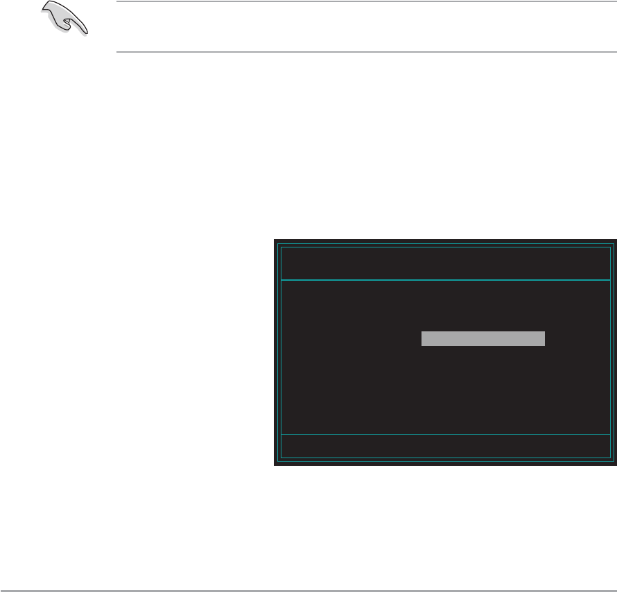
5. At the prompt, type
awdflashawdflash
awdflashawdflash
awdflash then press
<Enter>. The Award
BIOS Flash Utility screen
appears.
AwardBIOS Flash Utility for ASUS V1.01
(C) Phoenix Technologies Ltd. All Rights Reserved
Message: Please input File Name!
For K8T890-8237-A8V-E-00 DATE: 09/10/2004
Flash Type - PMC Pm49FL004T LPC/FWH
File Name to Program:
ASUS A8V-E DeluxeASUS A8V-E Deluxe
ASUS A8V-E DeluxeASUS A8V-E Deluxe
ASUS A8V-E Deluxe 4-34-3
4-34-3
4-3
6. Type the BIOS file name
in the File Name toFile Name to
File Name toFile Name to
File Name to
ProgramProgram
ProgramProgram
Program field, then
press <Enter>.
Do not turn off or reset the system during the flashing process!
AwardBIOS Flash Utility for ASUS V1.01
(C) Phoenix Technologies Ltd. All Rights Reserved
For K8T890-8237-A8V-E-00 DATE: 09/10/2004
Flash Type - PMC Pm49FL004T LPC/FWH
File Name to Program: A8V-E.BIN
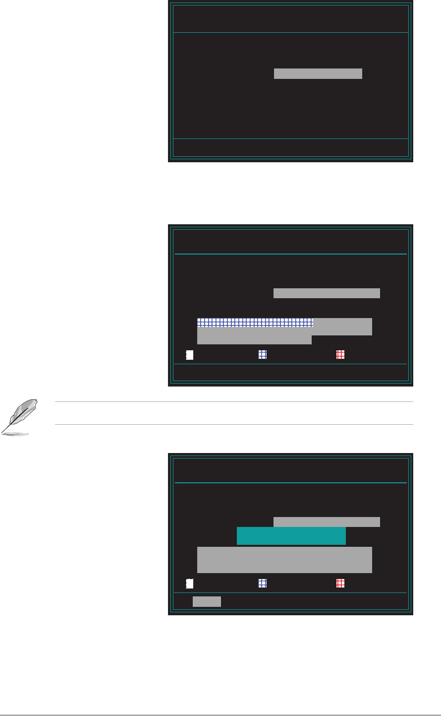
AwardBIOS Flash Utility for ASUS V1.01
(C) Phoenix Technologies Ltd. All Rights Reserved
Warning: Don’t Turn Off Power Or Reset System!
For K8T890-8237-A8V-E-00 DATE: 09/10/2004
Flash Type - PMC Pm49FL004T LPC/FWH
File Name to Program: A8V-E.BIN
Program Flashing Memory - OFE00 OK
Write OK No Update Write Fail
Message: Do You Want To Save Bios (Y/N)
9. The utility displays a
Flashing CompleteFlashing Complete
Flashing CompleteFlashing Complete
Flashing Complete
message indicating that
you have successfully
flashed the BIOS file.
Press <F1> to restart
the system.
AwardBIOS Flash Utility for ASUS V1.01
(C) Phoenix Technologies Ltd. All Rights Reserved
F1
Reset
For K8T890-8237-A8V-E-00 DATE: 09/10/2004
Flash Type - PMC Pm49FL004T LPC/FWH
File Name to Program: A8V-E.BIN
Flashing Complete
Press <F1> to Continue
Write OK No Update Write Fail
7. Press <N> when the utility prompts you to save the current BIOS file.
The following screen appears.
8. The utility verifies the
BIOS file in the floppy
disk and starts flashing
the BIOS file.
4-44-4
4-44-4
4-4 Chapter 4: BIOS setupChapter 4: BIOS setup
Chapter 4: BIOS setupChapter 4: BIOS setup
Chapter 4: BIOS setup
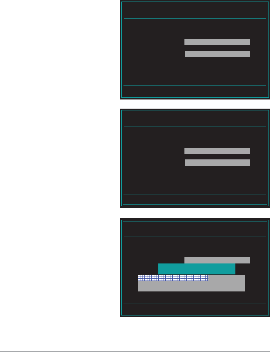
3. Type a filename for the
current BIOS file in the
Save current BIOSSave current BIOS
Save current BIOSSave current BIOS
Save current BIOS
as as
as as
as field, then press
<Enter>.
4. The utility saves the
current BIOS file to the
floppy disk, then returns
to the BIOS flashing
process.
4.1.34.1.3
4.1.34.1.3
4.1.3 Saving the current BIOS fileSaving the current BIOS file
Saving the current BIOS fileSaving the current BIOS file
Saving the current BIOS file
You can use the AwardBIOS Flash Utility to save the current BIOS file. You
can load the current BIOS file when the BIOS file gets corrupted during the
flashing process.
To save the current BIOS file using the AwardBIOS Flash Utility:
1. Follow steps 1 to 6 of the previous section.
2. Press <Y> when the
utility prompts you to
save the current BIOS
file. The following screen
appears.
AwardBIOS Flash Utility for ASUS V1.01
(C) Phoenix Technologies Ltd. All Rights Reserved
Message:
For K8T890-8237-A8V-E-00 DATE: 09/10/2004
Flash Type - PMC Pm49FL004T LPC/FWH
File Name to Program: A8V-E.BIN
Save current BIOS as:
AwardBIOS Flash Utility for ASUS V1.01
(C) Phoenix Technologies Ltd. All Rights Reserved
Message: Please Wait!
For K8T890-8237-A8V-E-00 DATE: 09/10/2004
Flash Type - PMC Pm49FL004T LPC/FWH
File Name to Program: A8V-E.BIN
Checksum: DAD6H
Save current BIOS as: old.bin
AwardBIOS Flash Utility for ASUS V1.01
(C) Phoenix Technologies Ltd. All Rights Reserved
Message: Please Wait!
For K8T890-8237-A8V-E-00 DATE: 09/10/2004
Flash Type - PMC Pm49FL004T LPC/FWH
File Name to Program: A8V-E.BIN
Now Backup System BIOS to
File!

ASUS A8V-E DeluxeASUS A8V-E Deluxe
ASUS A8V-E DeluxeASUS A8V-E Deluxe
ASUS A8V-E Deluxe 4-54-5
4-54-5
4-5
4.1.44.1.4
4.1.44.1.4
4.1.4 ASUS CrashFree BIOS 2 utilityASUS CrashFree BIOS 2 utility
ASUS CrashFree BIOS 2 utilityASUS CrashFree BIOS 2 utility
ASUS CrashFree BIOS 2 utility
The ASUS CrashFree BIOS 2 is an auto recovery tool that allows you to
restore the BIOS file when it fails or gets corrupted during the updating
process. You can update a corrupted BIOS file using the motherboard
support CD or the floppy disk that contains the updated BIOS file.
Prepare the motherboard support CD or the floppy disk containing the
updated motherboard BIOS before using this utility.
Recovering the BIOS from the support CDRecovering the BIOS from the support CD
Recovering the BIOS from the support CDRecovering the BIOS from the support CD
Recovering the BIOS from the support CD
To recover the BIOS from the support CD:
1. Turn on the system.
2. Insert the motherboard support CD to the optical drive.
3. The utility displays the following message and automatically checks
the CD for the BIOS file.
4. Restart the system after the utility completes the updating process.
DO NOT shut down or reset the system while updating the BIOS! Doing
so can cause system boot failure!
Award BootBlock BIOS v1.0
Copyright (c) 2000, Award Software, Inc.
BIOS ROM checksum error
Detecting IDE ATAPI device...
Found CDROM, try to Boot from it... Pass
When found, the utility reads the BIOS file and starts flashing the
corrupted BIOS file.
Award BootBlock BIOS v1.0
Copyright (c) 2000, Award Software, Inc.
BIOS ROM checksum error
Detecting IDE ATAPI device...

4-64-6
4-64-6
4-6 Chapter 4: BIOS setupChapter 4: BIOS setup
Chapter 4: BIOS setupChapter 4: BIOS setup
Chapter 4: BIOS setup
The recovered BIOS may not be the latest BIOS version for this
motherboard. Visit the ASUS website (www.asus.com) to download the
latest BIOS file.
Recovering the BIOS from a floppy diskRecovering the BIOS from a floppy disk
Recovering the BIOS from a floppy diskRecovering the BIOS from a floppy disk
Recovering the BIOS from a floppy disk
To recover the BIOS from the support CD:
1. Remove any CD from the optical drive, then turn on the system.
2. Insert the floppy disk with the original or updated BIOS file to the
floppy disk drive.
3. The utility displays the following message and automatically checks
the floppy disk for the original or updated BIOS file.
4. Restart the system after the utility completes the updating process.
DO NOT shut down or reset the system while updating the BIOS! Doing
so can cause system boot failure!
When no CD is found, the utility automatically checks the floppy drive
for the original or updated BIOS file. The utility then updates the
corrupted BIOS file.
Award BootBlock BIOS v1.0
Copyright (c) 2000, Award Software, Inc.
BIOS ROM checksum error
Detecting IDE ATAPI device...
Found CDROM, try to Boot from it... Fail
Detecting floppy drive A media...
Award BootBlock BIOS v1.0
Copyright (c) 2000, Award Software, Inc.
BIOS ROM checksum error
Detecting IDE ATAPI device...
ASUS A8V-E DeluxeASUS A8V-E Deluxe
ASUS A8V-E DeluxeASUS A8V-E Deluxe
ASUS A8V-E Deluxe 4-74-7
4-74-7
4-7
4.1.54.1.5
4.1.54.1.5
4.1.5 ASUS EZ Flash utilityASUS EZ Flash utility
ASUS EZ Flash utilityASUS EZ Flash utility
ASUS EZ Flash utility
The ASUS EZ Flash feature allows you to update the BIOS without having to
go through the long process of booting from a floppy disk and using a
DOS-based utility. The EZ Flash utility is built-in the BIOS chip so it is
accessible by pressing <Alt> + <F2> during the Power-On Self Tests
(POST).
To update the BIOS using EZ Flash:
1. Visit the ASUS website (www.asus.com) to download the latest BIOS
file for the motherboard.
2. Save the BIOS file to a floppy disk, then restart the system.
3. Press <Alt> + <F2> during POST to display the following.
Insert Disk then press Enter or ESC to continue POST
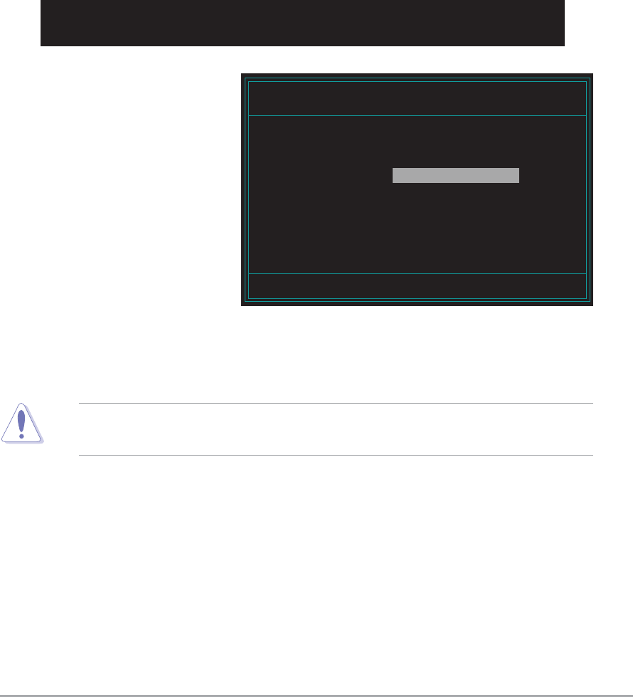
4. Insert the floppy disk
that contains the BIOS
file to the floppy disk
drive then press
<Enter>. The following
screen appears.
Do not shutdown or reset the system while updating the BIOS to
prevent system boot failure!
AwardBIOS Flash Utility for ASUS V1.01
(C) Phoenix Technologies Ltd. All Rights Reserved
Message: Please wait...
For NF-KC804-A8N-SLI-00 DATE: 11/18/2004
Flash Type - SST 49LF004A/B /3.3V
File Name to Program:
5. When the correct BIOS file is found, EZ Flash performs the BIOS
update process and automatically reboots the system when done.

4-84-8
4-84-8
4-8 Chapter 4: BIOS setupChapter 4: BIOS setup
Chapter 4: BIOS setupChapter 4: BIOS setup
Chapter 4: BIOS setup
Installing ASUS UpdateInstalling ASUS Update
Installing ASUS UpdateInstalling ASUS Update
Installing ASUS Update
To install ASUS Update:
1. Place the support CD in the optical drive. The Drivers Drivers
Drivers Drivers
Drivers menu appears.
2. Click the Utilities Utilities
Utilities Utilities
Utilities tab, then click Install ASUS UpdateInstall ASUS Update
Install ASUS UpdateInstall ASUS Update
Install ASUS Update
VX.XX.XXVX.XX.XX
VX.XX.XXVX.XX.XX
VX.XX.XX. See page 5-3 for the Utilities Utilities
Utilities Utilities
Utilities screen menu.
3. The ASUS Update utility is copied to your system.
4.1.64.1.6
4.1.64.1.6
4.1.6 ASUS Update utilityASUS Update utility
ASUS Update utilityASUS Update utility
ASUS Update utility
The ASUS Update is a utility that allows you to manage, save, and update
the motherboard BIOS in Windows
®
environment. The ASUS Update utility
allows you to:
•Save the current BIOS file
•Download the latest BIOS file from the Internet
•Update the BIOS from an updated BIOS file
•Update the BIOS directly from the Internet, and
•View the BIOS version information.
This utility is available in the support CD that comes with the motherboard
package.
ASUS Update requires an Internet connection either through a network
or an Internet Service Provider (ISP).
Quit all Windows
®
applications before you update the BIOS using this
utility.
ASUS A8V-E DeluxeASUS A8V-E Deluxe
ASUS A8V-E DeluxeASUS A8V-E Deluxe
ASUS A8V-E Deluxe 4-94-9
4-94-9
4-9
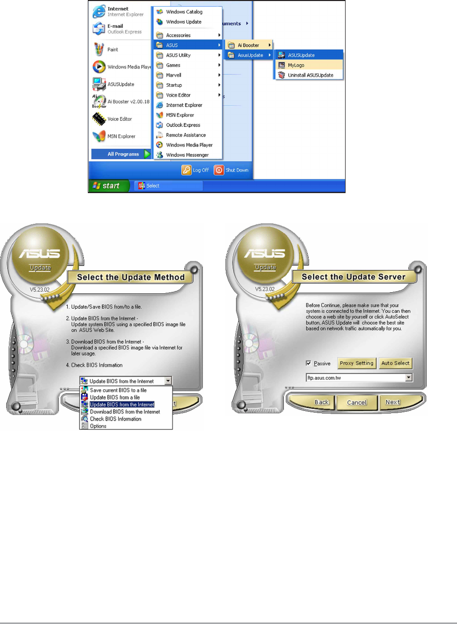
3. Select the ASUS FTP site
nearest you to avoid network
traffic, or click Auto SelectAuto Select
Auto SelectAuto Select
Auto Select.
Click NextNext
NextNext
Next.
Updating the BIOS through the InternetUpdating the BIOS through the Internet
Updating the BIOS through the InternetUpdating the BIOS through the Internet
Updating the BIOS through the Internet
To update the BIOS through the Internet:
1. Launch the ASUS Update utility from the Windows
®
desktop by clicking
Start Start
Start Start
Start > Programs Programs
Programs Programs
Programs > ASUS ASUS
ASUS ASUS
ASUS > ASUSUpdate ASUSUpdate
ASUSUpdate ASUSUpdate
ASUSUpdate > ASUSUpdateASUSUpdate
ASUSUpdateASUSUpdate
ASUSUpdate. The
ASUS Update main window appears.
2. Select Update BIOS fromUpdate BIOS from
Update BIOS fromUpdate BIOS from
Update BIOS from
the Internet the Internet
the Internet the Internet
the Internet option from the
drop-down menu, then click
NextNext
NextNext
Next.
4-104-10
4-104-10
4-10 Chapter 4: BIOS setupChapter 4: BIOS setup
Chapter 4: BIOS setupChapter 4: BIOS setup
Chapter 4: BIOS setup
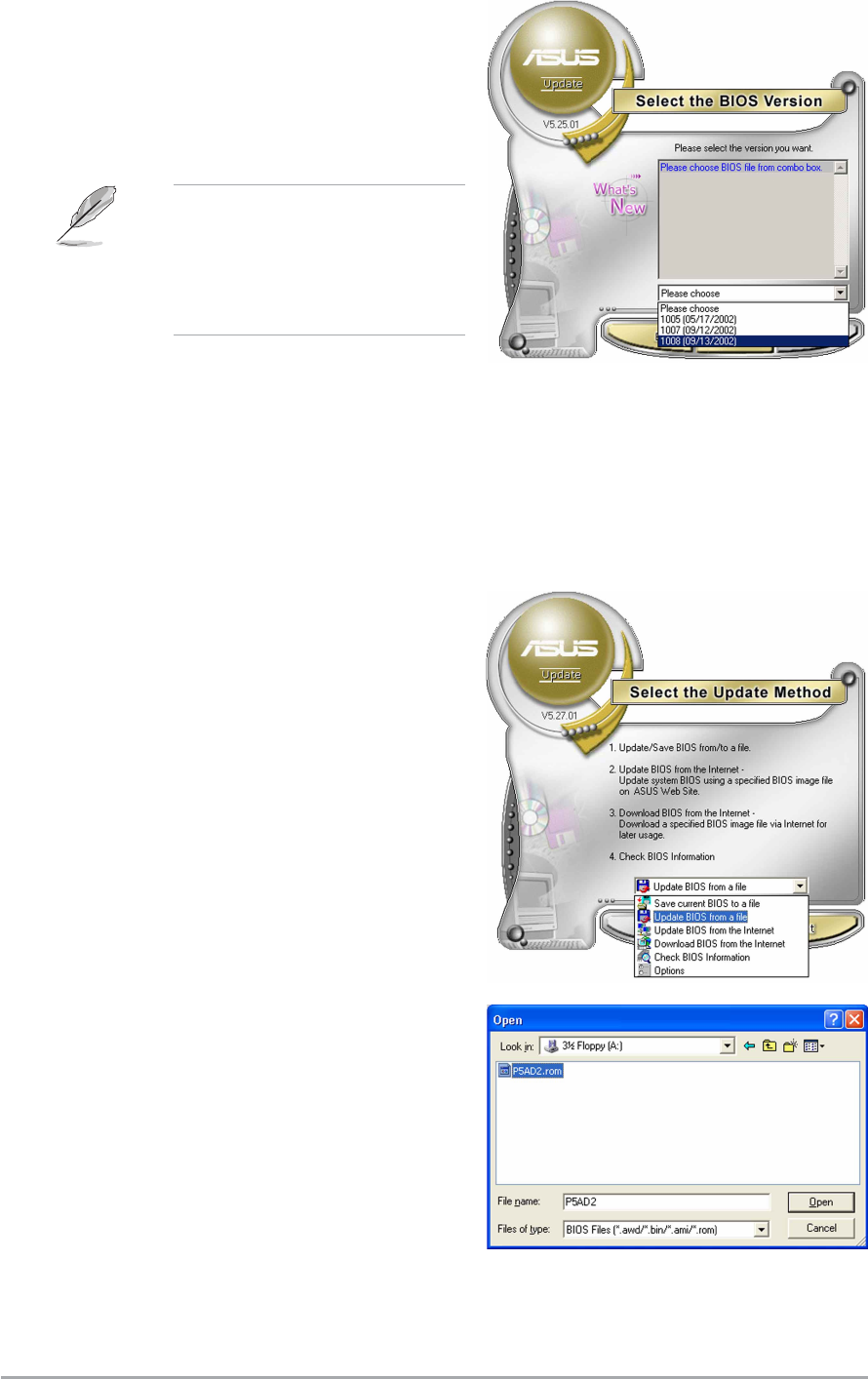
Updating the BIOS through a BIOS fileUpdating the BIOS through a BIOS file
Updating the BIOS through a BIOS fileUpdating the BIOS through a BIOS file
Updating the BIOS through a BIOS file
To update the BIOS through a BIOS file:
1. Launch the ASUS Update utility from the Windows
®
desktop by
clicking Start Start
Start Start
Start > Programs Programs
Programs Programs
Programs > ASUS ASUS
ASUS ASUS
ASUS > ASUSUpdate ASUSUpdate
ASUSUpdate ASUSUpdate
ASUSUpdate >
ASUSUpdateASUSUpdate
ASUSUpdateASUSUpdate
ASUSUpdate. The ASUS Update main window appears.
2. Select Update BIOS from aUpdate BIOS from a
Update BIOS from aUpdate BIOS from a
Update BIOS from a
file file
file file
file option from the drop-down
menu, then click NextNext
NextNext
Next.
4. From the FTP site, select the
BIOS version that you wish to
download. Click Next.
5. Follow the screen instructions to
complete the update process.
The ASUS Update utility is
capable of updating itself
through the Internet. Always
update the utility to avail all
its features.
3. Locate the BIOS file from the
Open Open
Open Open
Open window, then click SaveSave
SaveSave
Save.
4. Follow the screen instructions to
complete the update process.

ASUS A8V-E DeluxeASUS A8V-E Deluxe
ASUS A8V-E DeluxeASUS A8V-E Deluxe
ASUS A8V-E Deluxe 4-114-11
4-114-11
4-11
4.2 BIOS setup program
This motherboard supports a programmable Low-Pin Count (LPC) chip that
you can update using the provided utility described in section
“
4.1
Managing and updating your BIOS.”
Use the BIOS Setup program when you are installing a motherboard,
reconfiguring your system, or prompted to “Run Setup”. This section
explains how to configure your system using this utility.
Even if you are not prompted to use the Setup program, you can change
the configuration of your computer in the future. For example, you can
enable the security password feature or change the power management
settings. This requires you to reconfigure your system using the BIOS
Setup program so that the computer can recognize these changes and
record them in the CMOS RAM of the LPC chip.
The LPC chip on the motherboard stores the Setup utility. When you start
up the computer, the system provides you with the opportunity to run this
program. Press <Del>
during the Power-On Self-Test (POST) to enter the
Setup utility; otherwise, POST continues with its test routines.
If you wish to enter Setup after POST, restart the system by pressing
<Ctrl+Alt+Delete>, or by pressing the reset button on the system chassis.
You can also restart by turning the system off and then back on. Do this
last option only if the first two failed.
The Setup program is designed to make it as easy to use as possible. Being
a menu-driven program, it lets you scroll through the various sub-menus
and make your selections from the available options using the navigation
keys.
•The default BIOS settings for this motherboard apply for most
conditions to ensure optimum performance. If the system becomes
unstable after changing any BIOS settings, load the default settings
to ensure system compatibility and stability. Select the LoadLoad
LoadLoad
Load
Default SettingsDefault Settings
Default SettingsDefault Settings
Default Settings item under the Exit Menu. See section “4.7 Exit
Menu.”
•The BIOS setup screens shown in this section are for reference
purposes only, and may not exactly match what you see on your
screen.
•Visit the ASUS website (www.asus.com) to download the latest BIOS
file for this motherboard and .
4-124-12
4-124-12
4-12 Chapter 4: BIOS setupChapter 4: BIOS setup
Chapter 4: BIOS setupChapter 4: BIOS setup
Chapter 4: BIOS setup
F1:Help ↑↓ : Select Item -/+: Change Value F5: Setup Defaults
ESC: Exit →←: Select Menu Enter: Select Sub-menu F10: Save and Exit
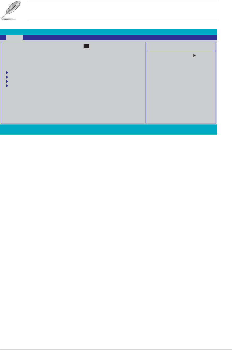
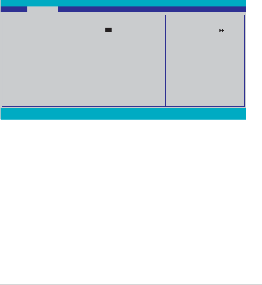
Phoenix-Award BIOS CMOS Setup Utility
Main Advanced Power Boot Exit
Select Menu
Item Specific Help
Change the day, month,
year and century.
System Time 15 : 30 : 36
System Date Wed, Sep 15 2004
Language [English]
Legacy Diskette A: [1.44M, 3.5 in.]
Primary IDE Master [ST321122A]
Primary IDE Slave [ASUS CDS520/A]
Secondary IDE Master [None]
Secondary IDE Slave [None]
HDD SMART Monitoring [Disabled]
Installed Memory 256MB
4.2.24.2.2
4.2.24.2.2
4.2.2 Menu barMenu bar
Menu barMenu bar
Menu bar
The menu bar on top of the screen has the following main items:
MainMain
MainMain
Main For changing the basic system configuration
AdvancedAdvanced
AdvancedAdvanced
Advanced For changing the advanced system settings
PowerPower
PowerPower
Power For changing the advanced power management (APM)
configuration
BootBoot
BootBoot
Boot For changing the system boot configuration
ExitExit
ExitExit
Exit For selecting the exit options and loading default settings
To select an item on the menu bar, press the right or left arrow key on the
keyboard until the desired item is highlighted.
4.2.14.2.1
4.2.14.2.1
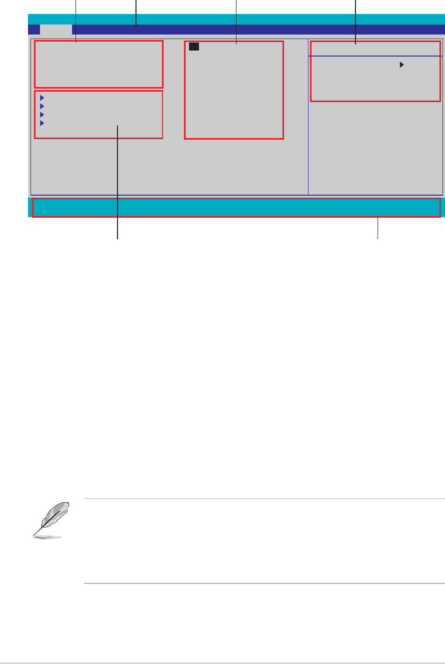
4.2.1 BIOS menu screenBIOS menu screen
BIOS menu screenBIOS menu screen
BIOS menu screen
•The BIOS setup screens shown in this chapter are for reference
purposes only, and may not exactly match what you see on your
screen.
•Visit the ASUS website (www.asus.com) to download the latest BIOS
information.
Legend barLegend bar
Legend barLegend bar
Legend bar
General helpGeneral help
General helpGeneral help
General help
Menu barMenu bar
Menu barMenu bar
Menu bar
Sub-menu itemsSub-menu items
Sub-menu itemsSub-menu items
Sub-menu items
Configuration fieldsConfiguration fields
Configuration fieldsConfiguration fields
Configuration fields
Menu itemsMenu items
Menu itemsMenu items
Menu items

ASUS A8V-E DeluxeASUS A8V-E Deluxe
ASUS A8V-E DeluxeASUS A8V-E Deluxe
ASUS A8V-E Deluxe 4-134-13
4-134-13
4-13
4.2.44.2.4
4.2.44.2.4
4.2.4 Menu itemsMenu items
Menu itemsMenu items
Menu items
The highlighted item on the menu bar displays the specific items for that
menu. For example, selecting Main Main
Main Main
Main shows the Main menu items.
The other items (Advanced, Power, Boot, and Exit) on the menu bar have
their respective menu items.
4.2.54.2.5
4.2.54.2.5
4.2.5 Sub-menu itemsSub-menu items
Sub-menu itemsSub-menu items
Sub-menu items
A solid triangle before each item on any menu screen means that the iteam
has a sub-menu. To display the sub-menu, select the item and press
<Enter>.
4.2.64.2.6
4.2.64.2.6
4.2.6 Configuration fieldsConfiguration fields
Configuration fieldsConfiguration fields
Configuration fields
These fields show the values for the menu items. If an item is
user-configurable, you can change the value of the field opposite the item.
You cannot select an item that is not user-configurable.
A configurable field is enclosed in brackets, and is highlighted when
selected. To change the value of a field, select it then press <Enter> to
display a list of options. Refer to “4.2.7 Pop-up window.”
4.2.34.2.3
4.2.34.2.3
4.2.3 Legend barLegend bar
Legend barLegend bar
Legend bar
At the bottom of the Setup screen is a legend bar. The keys in the legend
bar allow you to navigate through the various setup menus. The following
table lists the keys found in the legend bar with their corresponding
functions.
Navigation KeyNavigation Key
Navigation KeyNavigation Key
Navigation Key FunctionFunction
FunctionFunction
Function
<F1><F1>
<F1><F1>
<F1> Displays the General Help screen
<F5><F5>
<F5><F5>
<F5> Loads setup default values
<Esc><Esc>
<Esc><Esc>
<Esc> Exits the BIOS setup or returns to the main menu
from a sub-menu
Left or Right arrowLeft or Right arrow
Left or Right arrowLeft or Right arrow
Left or Right arrow Selects the menu item to the left or right
Up or Down arrowUp or Down arrow
Up or Down arrowUp or Down arrow
Up or Down arrow Moves the highlight up or down between fields
Page Down or – (minus)Page Down or – (minus)
Page Down or – (minus)Page Down or – (minus)
Page Down or – (minus) Scrolls backward through the values for the
highlighted field
Page Up or + (plus)Page Up or + (plus)
Page Up or + (plus)Page Up or + (plus)
Page Up or + (plus) Scrolls forward through the values for the highlighted
field
<Enter><Enter>
<Enter><Enter>
<Enter> Brings up a selection menu for the highlighted field
<F10><F10>
<F10><F10>
<F10> Saves changes and exit
4-144-14
4-144-14
4-14 Chapter 4: BIOS setupChapter 4: BIOS setup
Chapter 4: BIOS setupChapter 4: BIOS setup
Chapter 4: BIOS setup
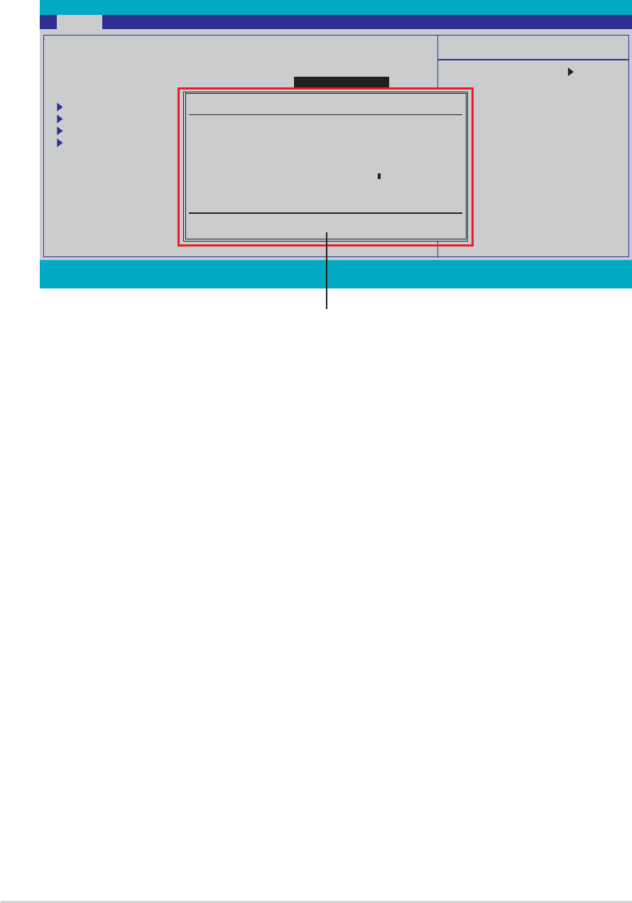
4.2.74.2.7
4.2.74.2.7
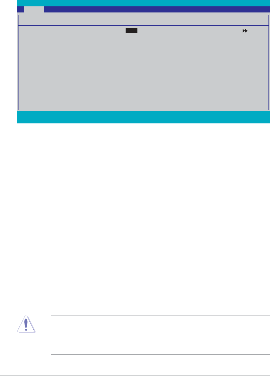
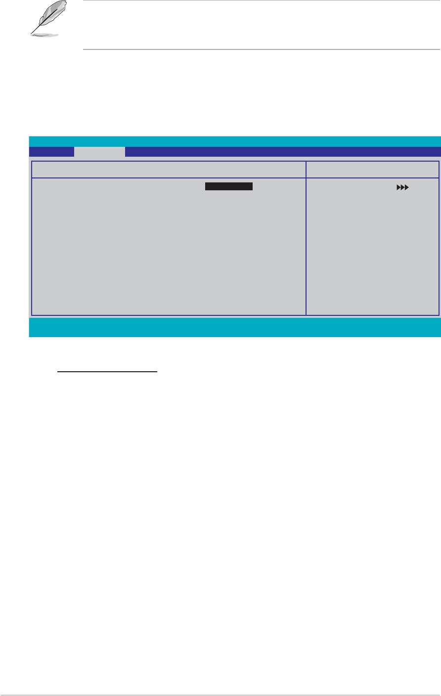
4.2.7 Pop-up windowPop-up window
Pop-up windowPop-up window
Pop-up window
Select a menu item then press <Enter> to display a pop-up window with
the configuration options for that item.
F1:Help ↑↓ : Select Item -/+: Change Value F5: Setup Defaults
ESC: Exit →←: Select Menu Enter: Select Sub-menu F10: Save and Exit
Phoenix-Award BIOS CMOS Setup Utility
Main Advanced Power Boot Exit
Select Menu
Item Specific Help
Specifies the capacity
and physical size of
diskette drive A.
System Time 15 : 30 : 36
System Date Wed, Sep 15 2004
Legacy Diskette A: [1.44M, 3.5 in.]
Primary IDE Master [ST321122A]
Primary IDE Slave [ASUS CDS520/A]
Secondary IDE Master [None]
Secondary IDE Slave [None]
HDD SMART Monitoring [Disabled]
Installed Memory 256MB
Legacy Diskette A:
Disabled ..... [ ]
360K , 5.25 in. ..... [ ]
1.2M , 5.25 in. ..... [ ]
720K , 3.5 in. ..... [ ]
1.44M, 3.5 in. ..... [ ]
2.88M, 3.5 in. ..... [ ]
↑↓ :Move ENTER:Accept ESC:Abort
Pop-up menuPop-up menu
Pop-up menuPop-up menu
Pop-up menu
4.2.84.2.8
4.2.84.2.8
4.2.8 General helpGeneral help
General helpGeneral help
General help
At the top right corner of the menu screen is a brief description of the
selected item.
ASUS A8V-E DeluxeASUS A8V-E Deluxe
ASUS A8V-E DeluxeASUS A8V-E Deluxe
ASUS A8V-E Deluxe 4-154-15
4-154-15
4-15
F1:Help ↑↓ : Select Item -/+: Change Value F5: Setup Defaults
ESC: Exit →←: Select Menu Enter: Select Sub-menu F10: Save and Exit
Phoenix-Award BIOS CMOS Setup Utility
Main Advanced Power Boot Exit
Select Menu
Item Specific Help
Change the day, month,
year and century.
System Time 15 : 30 : 36
System Date Wed, Sep 15 2004
Language [English]
Legacy Diskette A: [1.44M, 3.5 in.]
Primary IDE Master [ST321122A]
Primary IDE Slave [ASUS CDS520/A]
Secondary IDE Master [None]
Secondary IDE Slave [None]
HDD SMART Monitoring [Disabled]
Installed Memory 256MB
4.3 Main menu
When you enter the BIOS Setup program, the Main menu screen appears,
giving you an overview of the basic system information.
Refer to section “4.2.1 BIOS menu screen” for information on the menu
screen items and how to navigate through them.
4.3.14.3.1
4.3.14.3.1
4.3.1 System Time [xx:xx:xxxx]System Time [xx:xx:xxxx]
System Time [xx:xx:xxxx]System Time [xx:xx:xxxx]
System Time [xx:xx:xxxx]
Allows you to set the system time.
4.3.24.3.2
4.3.24.3.2
4.3.2 System Date [Day xx/xx/xxxx]System Date [Day xx/xx/xxxx]
System Date [Day xx/xx/xxxx]System Date [Day xx/xx/xxxx]
System Date [Day xx/xx/xxxx]
Allows you to set the system date.
4.3.34.3.3
4.3.34.3.3
4.3.3 Language [English]Language [English]
Language [English]Language [English]
Language [English]
Allows you to choose the BIOS language version from the options.
Configuration options: [English] [French] [German]
4.3.44.3.4
4.3.44.3.4
4.3.4 Legacy Diskette A [1.44M, 3.5 in.]Legacy Diskette A [1.44M, 3.5 in.]
Legacy Diskette A [1.44M, 3.5 in.]Legacy Diskette A [1.44M, 3.5 in.]
Legacy Diskette A [1.44M, 3.5 in.]
Sets the type of floppy drive installed. Configuration options: [Disabled]
[360K, 5.25 in.] [1.2M , 5.25 in.] [720K , 3.5 in.] [1.44M, 3.5 in.]
[2.88M, 3.5 in.]
4-164-16
4-164-16
4-16 Chapter 4: BIOS setupChapter 4: BIOS setup
Chapter 4: BIOS setupChapter 4: BIOS setup
Chapter 4: BIOS setup
Before attempting to configure a hard disk drive, make sure you have
the correct configuration information supplied by the drive
manufacturer. Incorrect settings may cause the system to fail to
recognize the installed hard disk.
4.3.54.3.5
4.3.54.3.5
4.3.5 Primary and Secondary IDE Master/SlavePrimary and Secondary IDE Master/Slave
Primary and Secondary IDE Master/SlavePrimary and Secondary IDE Master/Slave
Primary and Secondary IDE Master/Slave
While entering Setup, the BIOS automatically detects the presence of IDE
devices. There is a separate sub-menu for each IDE device. Select a device
item then press <Enter> to display the IDE device information.
The BIOS automatically detects the values opposite the dimmed items
(Capacity, Cylinder, Head, Sector and Transfer Mode). These values are not
user-configurable. These items show N/A if no IDE device is installed in the
system.
Primary/Secondary IDE Master/Slave [Auto]Primary/Secondary IDE Master/Slave [Auto]
Primary/Secondary IDE Master/Slave [Auto]Primary/Secondary IDE Master/Slave [Auto]
Primary/Secondary IDE Master/Slave [Auto]
Select [Auto] to automatically detect an IDE hard disk drive. If automatic
detection is successful, the BIOS automatically fills in the correct values for
the remaining fields on this sub-menu. If the hard disk was already
formatted on a previous system, the setup BIOS may detect incorrect
parameters. Select [Manual] to manually enter the IDE hard disk drive
parameters. If no drive is installed select [None].
Configuration options: [None] [Auto] [Manual]
Access Mode [Auto]Access Mode [Auto]
Access Mode [Auto]Access Mode [Auto]
Access Mode [Auto]
The default [Auto] allows automatic detection of an IDE hard disk drive.
Select [CHS] for this item if you set the IDE Primary Master/Slave to
[Manual]. Configuration options: [CHS] [LBA] [Large] [Auto]
F1:Help ↑↓ : Select Item -/+: Change Value F5: Setup Defaults
ESC: Exit →←: Select Menu Enter: Select Sub-menu F10: Save and Exit
Phoenix-Award BIOS CMOS Setup Utility
Main
Select Menu
Item Specific Help
Press [Enter] to
select
Primary IDE Master
Primary IDE Master [Auto]
Access Mode [Auto]
Capacity 13579 MB
Cylinder 26310
Head 16
Sector 63
PIO Mode [Auto]
UDMA Mode [Auto]
Transfer Mode UDMA 4

ASUS A8V-E DeluxeASUS A8V-E Deluxe
ASUS A8V-E DeluxeASUS A8V-E Deluxe
ASUS A8V-E Deluxe 4-174-17
4-174-17
4-17
CapacityCapacity
CapacityCapacity
Capacity
Displays the auto-detected hard disk capacity. This item is not
configurable.
CylinderCylinder
CylinderCylinder
Cylinder
Shows the number of the hard disk cylinders. This item is not configurable.
HeadHead
HeadHead
Head
Shows the number of the hard disk read/write heads. This item is not
configurable.
SectorSector
SectorSector
Sector
Shows the number of sectors per track. This item is not configurable.
PIO ModePIO Mode
PIO ModePIO Mode
PIO Mode
Sets the PIO mode for the IDE device.
Configuration options: [Auto] [Mode 0] [Mode 1] [Mode 2] [Mode 3]
[Mode 4]
UDMA ModeUDMA Mode
UDMA ModeUDMA Mode
UDMA Mode
Disables or sets the UDMA mode. Configuration options: [Disabled] [Auto]
Transfer ModeTransfer Mode
Transfer ModeTransfer Mode
Transfer Mode
Shows the Transfer mode. This item is not configurable.
After entering the IDE hard disk drive information into BIOS, use a disk
utility, such as FDISK, to partition and format new IDE hard disk drives.
This is necessary so that you can write or read data from the hard disk.
Make sure to set the partition of the Primary IDE hard disk drives to
active.
4.3.64.3.6
4.3.64.3.6
4.3.6 HDD SMART MonitoringHDD SMART Monitoring
HDD SMART MonitoringHDD SMART Monitoring
HDD SMART Monitoring
Enables or disables the hard disk Self-Monitoring Analysis & Reporting
Technology (SMART) feature. Configuration options: [Disabled] [Enabled]
4.3.74.3.7
4.3.74.3.7
4.3.7 Installed MemoryInstalled Memory
Installed MemoryInstalled Memory
Installed Memory
Shows the size of installed memory.
4-184-18
4-184-18
4-18 Chapter 4: BIOS setupChapter 4: BIOS setup
Chapter 4: BIOS setupChapter 4: BIOS setup
Chapter 4: BIOS setup
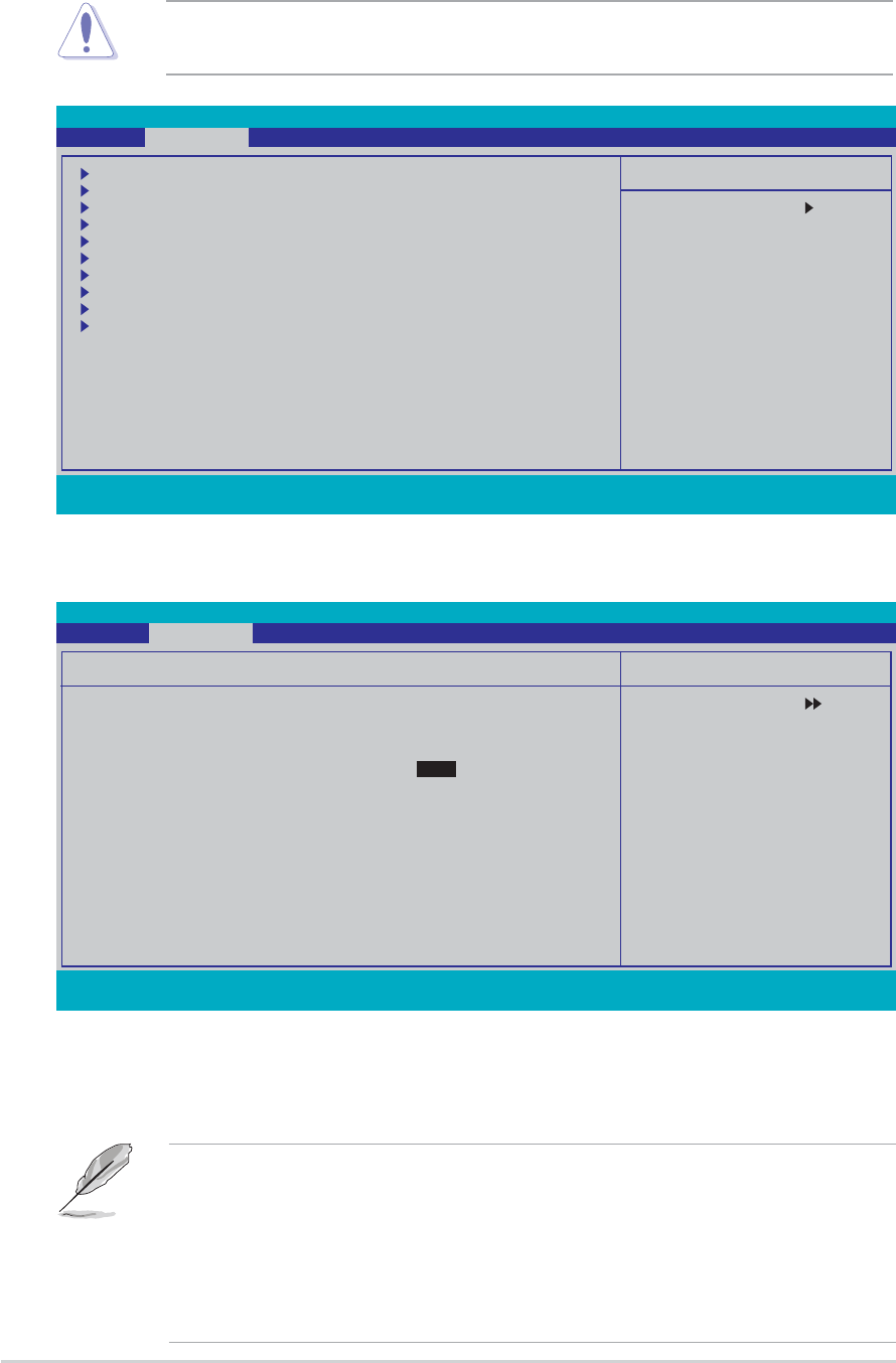
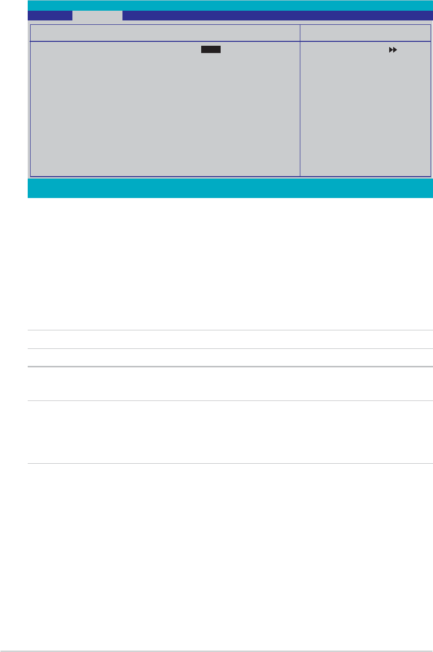
Phoenix-Award BIOS CMOS Setup Utility
Main Advanced Power Boot Exit
Select Menu
Item Specific Help
Press Enter to Set
CPU Configuration
Chipset
PCIPnP
Onboard Device Configuration
USB Configuration
JumperFree Configuration
LAN Cable Status
PEG Link Mode
Speech Configuration
Instant Music
4.4.14.4.1
4.4.14.4.1
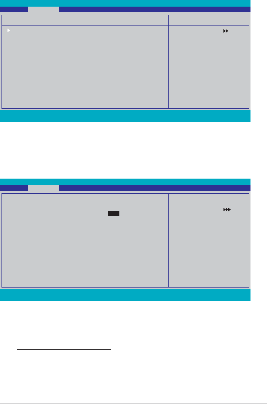
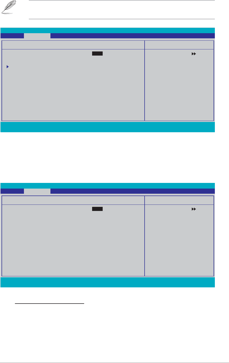
4.4.1 CPU ConfigurationCPU Configuration
CPU ConfigurationCPU Configuration
CPU Configuration
Cool N’ Quiet [Auto]Cool N’ Quiet [Auto]
Cool N’ Quiet [Auto]Cool N’ Quiet [Auto]
Cool N’ Quiet [Auto]
Allows you to disable or set the AMD Cool ‘n’ Quiet!™ Technology feature.
Configuration options: [Auto] [Disabled]
• Make sure that the above item is set to Auto Auto
Auto Auto
Auto if you want to use
the AMD CPU Cool ‘n’ Quiet!™ Technology feature.
•This feature requires the AMD CPU heatsink and fan assembly with
monitor chip. If you purchased a separate heatsink and fan package,
use the ASUS Q-Fan Technology feature to automatically adjust the
CPU fan speed according to your system loading.
F1:Help ↑↓ : Select Item -/+: Change Value F5: Setup Defaults
ESC: Exit →←: Select Menu Enter: Select Sub-menu F10: Save and Exit
Select Menu
Item Specific Help
CPU Configuration
CPU Type AMD Athlon(tm) 64 Processor 3400+
CPU Speed 2200MHz
Cache RAM 512K
Current FSB Frequency 200 MHz
AMD K8 Cool’n’Quiet control [Auto]
Phoenix-Award BIOS CMOS Setup Utility
Advanced
4.4 Advanced menu
The Advanced menu items allow you to change the settings for the CPU
and other system devices.
Take caution when changing the settings of the Advanced menu items.
Incorrect field values can cause the system to malfunction.
F1:Help ↑↓ : Select Item -/+: Change Value F5: Setup Defaults
ESC: Exit →←: Select Menu Enter: Select Sub-menu F10: Save and Exit
ASUS A8V-E DeluxeASUS A8V-E Deluxe
ASUS A8V-E DeluxeASUS A8V-E Deluxe
ASUS A8V-E Deluxe 4-194-19
4-194-19
4-19
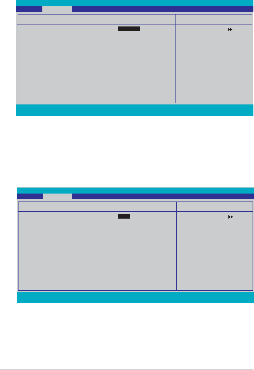
4.4.24.4.2
4.4.24.4.2
4.4.2 ChipsetChipset
ChipsetChipset
Chipset
DRAM ConfigurationDRAM Configuration
DRAM ConfigurationDRAM Configuration
DRAM Configuration
The items in this sub-menu show the DRAM-related information
auto-detected by the BIOS.
F1:Help ↑↓ : Select Item -/+: Change Value F5: Setup Defaults
ESC: Exit →←: Select Menu Enter: Select Sub-menu F10: Save and Exit
Select Menu
Item Specific Help
Place an artificial
memory clock limit on
the system. Memory is
prevented from
running faster than
this frequency.
DRAM Configuration
Current DRAM Frequency 166 MHz
Max Memclock (MHz) [Auto]
CAS# latency (Tcl) [Auto]
RAS# to CAS# delay (Trcd) [Auto]
Min RAS# active time(Tras) [Auto]
Row precharge Time (Trp) [Auto]
Master ECC Enable [Enabled]
Phoenix-Award BIOS CMOS Setup Utility
Advanced
F1:Help ↑↓ : Select Item -/+: Change Value F5: Setup Defaults
ESC: Exit →←: Select Menu Enter: Select Sub-menu F10: Save and Exit
Select Menu
Item Specific Help
DRAM timing and
control
Chipset
DRAM Configuration
Upstream LDT Bus Width [16 bit]
Downstream LDT Bus Width [16 bit]
LDT Bus Frequency [Auto]
VLink Mode Selection [By Auto]
PEG Data Scrambling [Auto]
PE0-PE3 Data Scrambling [Enable]
Init Display First [PCI Slot
Chipset Vcore Adjustment [+1.6 V]
Phoenix-Award BIOS CMOS Setup Utility
Advanced
Current DRAM Frequency
Shows the Transfer mode. This item is not configurable.
Max Memclock (MHz) [Auto]
Sets the maximum operating memory clock.
Configuration options: [Auto] [DDR200] [DDR266] [DDR333]
[DDR400]

4-204-20
4-204-20
4-20 Chapter 4: BIOS setupChapter 4: BIOS setup
Chapter 4: BIOS setupChapter 4: BIOS setup
Chapter 4: BIOS setup
CAS# latency (Tcl) [Auto]
Controls the latency between the SDRAM read command and the time
the data actually becomes available. Configuration options: [Auto]
[2.0] [2.5] [3.0]
RAS# to CAS# delay (Trcd) [Auto]
Controls the latency between the DDR SDRAM active command and
the read/write command. Configuration options: [Auto] [2] [3] [4]
[5] [6] [7]
Min RAS# active time (Tras) [Auto]
Sets the minimum RAS# active time. Configuration options: [Auto] [5]
[6] [7] [8] [9] [10] [11] [12] [13] [14] [15]
Row precharge Time (Trp) [Auto]
Sets the Row precharge time. Configuration options: [Auto] [2] [3]
[4] [5] [6]
Master ECC Enable [Enabled]
Enables or disables the Master ECC feature.
Configuration options: [Disabled] [Enabled]
Upstream LDT Bus Width [16 bit]Upstream LDT Bus Width [16 bit]
Upstream LDT Bus Width [16 bit]Upstream LDT Bus Width [16 bit]
Upstream LDT Bus Width [16 bit]
Sets the upstream Lightning Data Transport (LDT) Bus Width.
Configuration options: [ 8 bit] [16 bit]
Downstream LDT Bus Width [16 bit]Downstream LDT Bus Width [16 bit]
Downstream LDT Bus Width [16 bit]Downstream LDT Bus Width [16 bit]
Downstream LDT Bus Width [16 bit]
Sets the downstream Lightning Data Transport (LDT) Bus Width.
Configuration options: [ 8 bit] [16 bit]
LDT Bus Frequency [Auto]LDT Bus Frequency [Auto]
LDT Bus Frequency [Auto]LDT Bus Frequency [Auto]
LDT Bus Frequency [Auto]
Sets the Lightning Data Transport (LDT) Bus frequency.
Configuration options: [Auto] [1 GHz] [800 MHz] [600 MHz] [400 MHz]
[200 MHz]
VLink Mode Selection [By Auto]VLink Mode Selection [By Auto]
VLink Mode Selection [By Auto]VLink Mode Selection [By Auto]
VLink Mode Selection [By Auto]
Sets the VLink mode. Configuration options: [By Auto] [Mode 0] [Mode 1]
[Mode 2] [Mode 3] [Mode 4]
PEG Data Scrambling [Auto]PEG Data Scrambling [Auto]
PEG Data Scrambling [Auto]PEG Data Scrambling [Auto]
PEG Data Scrambling [Auto]
Disables or enables the PCI Express™ graphics data scrambling.
Configuration options: [Auto] [Disable] [Enable]
ASUS A8V-E DeluxeASUS A8V-E Deluxe
ASUS A8V-E DeluxeASUS A8V-E Deluxe
ASUS A8V-E Deluxe 4-214-21
4-214-21
4-21
PE0-PE3 Data Scrambling [Enable]PE0-PE3 Data Scrambling [Enable]
PE0-PE3 Data Scrambling [Enable]PE0-PE3 Data Scrambling [Enable]
PE0-PE3 Data Scrambling [Enable]
Disables or enables the PCI Express™ 0 to PCI Express™ 3 data scrambling.
Configuration options: [Disable] [Enable]
Init Display First [PCI Slot]Init Display First [PCI Slot]
Init Display First [PCI Slot]Init Display First [PCI Slot]
Init Display First [PCI Slot]
Allows you to select the graphics controller to use as the primary boot
device. Configuration options: [PCI Slot] [PCIEx]
Chipset Vcore Adjustment [+1.5 V]Chipset Vcore Adjustment [+1.5 V]
Chipset Vcore Adjustment [+1.5 V]Chipset Vcore Adjustment [+1.5 V]
Chipset Vcore Adjustment [+1.5 V]
Sets the chipset vcore adjustment voltage.
Configuration options: [+1.5 V] [+1.6 V]
F1:Help ↑↓ : Select Item -/+: Change Value F5: Setup Defaults
ESC: Exit →←: Select Menu Enter: Select Sub-menu F10: Save and Exit
Select Menu
Item Specific Help
Select Yes if you are
using a Plug and Play
capable operating
system. Select No if you
need the BIOS to
configure non-boot
devices.
Frequency/Voltage control
Plug & Play O/S [No]
Resources Controlled By [Auto]
xIRQ Resources
PCI/VGA Palette Snoop [Disabled]
Assign IRQ for VGA [Enabled]
** PCI Express relative items **
Maximum Payload Size [4096]
Phoenix-Award BIOS CMOS Setup Utility
Advanced
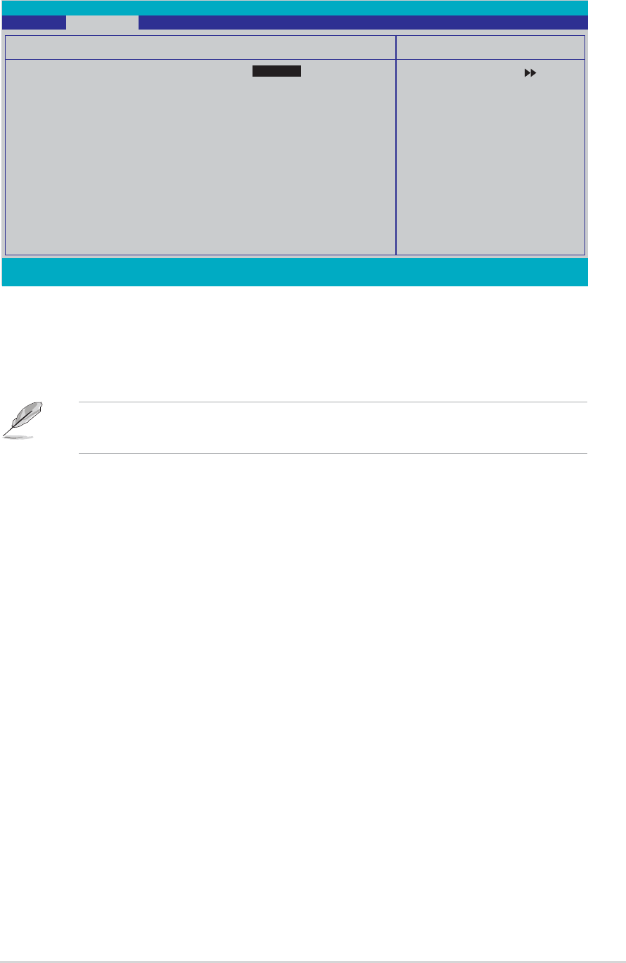
4.4.34.4.3
4.4.34.4.3
4.4.3 PCI PnPPCI PnP
PCI PnPPCI PnP
PCI PnP
Plug & Play O/S [No]Plug & Play O/S [No]
Plug & Play O/S [No]Plug & Play O/S [No]
Plug & Play O/S [No]
When set to [No], the BIOS configures all the devices in the system. When
set to [Yes] and if you install a Plug and Play operating system, the
operating system configures the Plug and Play devices not required for
boot. Configuration options: [No] [Yes]
Resources Controlled By [Auto]Resources Controlled By [Auto]
Resources Controlled By [Auto]Resources Controlled By [Auto]
Resources Controlled By [Auto]
When set to [Auto], the BIOS automatically configures all the boot and
Plug and Play compatible devices. Set to [Manual] if you want to assign the
IRQ DMA and memory base address fields.
Configuration options: [Auto] [Manual]
4-224-22
4-224-22
4-22 Chapter 4: BIOS setupChapter 4: BIOS setup
Chapter 4: BIOS setupChapter 4: BIOS setup
Chapter 4: BIOS setup
IRQ ResourcesIRQ Resources
IRQ ResourcesIRQ Resources
IRQ Resources
This sub-menu is activated only when the Resources Controlled ByResources Controlled By
Resources Controlled ByResources Controlled By
Resources Controlled By
item is set to Manual.
F1:Help ↑↓ : Select Item -/+: Change Value F5: Setup Defaults
ESC: Exit →←: Select Menu Enter: Select Sub-menu F10: Save and Exit
Select Menu
Item Specific Help
Legacy ISA for devices
compliant with the
original PC AT bus
specification, PCI/ISA
PnP for devices
compliant with the
Plug and Play standard
whether designed for
PCI or ISA bus
architecture
IRQ Resources
IRQ-3 assigned to [PCI Device]
IRQ-4 assigned to [PCI Device]
IRQ-5 assigned to [PCI Device]
IRQ-7 assigned to [PCI Device]
IRQ-9 assigned to [PCI Device]
IRQ-10 assigned to [PCI Device]
IRQ-11 assigned to [PCI Device]
IRQ-12 assigned to [PCI Device]
IRQ-14 assigned to [PCI Device]
IRQ-15 assigned to [PCI Device]
Phoenix-Award BIOS CMOS Setup Utility
Advanced
IRQ-xx assigned to
When set to [PCI Device], the specific IRQ is free for use of PCI/PnP
devices. When set to [Reserved], the IRQ is reserved for legacy ISA
devices. Configuration options: [PCI Device] [Reserved]
PCI/VGA Palette Snoop [Disabled]PCI/VGA Palette Snoop [Disabled]
PCI/VGA Palette Snoop [Disabled]PCI/VGA Palette Snoop [Disabled]
PCI/VGA Palette Snoop [Disabled]
When set to [Enabled], the pallete snooping feature informs the PCI
devices that an ISA graphics device is installed in the system so that the
latter can function correctly. Configuration options: [Disabled] [Enabled]
Assign IRQ for VGA [Enabled]Assign IRQ for VGA [Enabled]
Assign IRQ for VGA [Enabled]Assign IRQ for VGA [Enabled]
Assign IRQ for VGA [Enabled]
When set to [Enabled], the BIOS assigns an IRQ to PCI VGA card if the card
requests for an IRQ. When set to [Disabled], the BIOS does not assign an
IRQ to the PCI VGA card even if requested.
Configuration options: [Disabled] [Enabled]
Maximum Payload Size [4096]Maximum Payload Size [4096]
Maximum Payload Size [4096]Maximum Payload Size [4096]
Maximum Payload Size [4096]
Sets the maximum payload size in bytes for PCI Express devices.
Configuration options: [128] [256] [512] [1024] [2048] [4096]
When the item Resources Controlled By is set to [Auto], the item IRQ
Resources is grayed out and not user-configurable. Refer to the section
“IRQ Resources” for information on how to enable this item.

ASUS A8V-E DeluxeASUS A8V-E Deluxe
ASUS A8V-E DeluxeASUS A8V-E Deluxe
ASUS A8V-E Deluxe 4-234-23
4-234-23
4-23
F1:Help ↑↓ : Select Item -/+: Change Value F5: Setup Defaults
ESC: Exit →←: Select Menu Enter: Select Sub-menu F10: Save and Exit
Select Menu
Item Specific Help
Enable/Disable Onboard
1394 device support.
Onboard Device Configuration
Onboard 1394 Controller [Enabled]
Onboard PCIE GbE LAN [Enabled]
Onboard LAN Boot ROM [Disabled]
Onboard Wireless LAN [Enabled]
OnChip SATA [Enabled]
SATA Mode [RAID]
Onboard AC97 Audio [Auto]
Serial Port1 Address [3F8/IRQ4]
Parallel Port Address [378/IRQ7]
Parallel Port Mode [ECP+EPP]
EPP Mode Select [EPP1.7]
ECP MOde Use DMA [3]
Game Port Address [201]
Midi Port Address [330]
Midi Port IRQ [10]
Phoenix-Award BIOS CMOS Setup Utility
Advanced
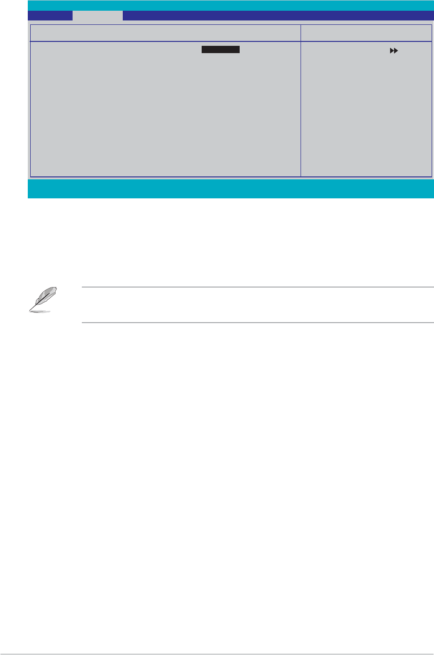
4.4.44.4.4
4.4.44.4.4
4.4.4 Onboard Devices ConfigurationOnboard Devices Configuration
Onboard Devices ConfigurationOnboard Devices Configuration
Onboard Devices Configuration
Onboard 1394 Controller [Enabled]Onboard 1394 Controller [Enabled]
Onboard 1394 Controller [Enabled]Onboard 1394 Controller [Enabled]
Onboard 1394 Controller [Enabled]
Enables or disables the onboard 1394 controller.
Configuration options: [Enabled] [Disabled]
OnBoard PCIEX GbE LAN [Enabled]OnBoard PCIEX GbE LAN [Enabled]
OnBoard PCIEX GbE LAN [Enabled]OnBoard PCIEX GbE LAN [Enabled]
OnBoard PCIEX GbE LAN [Enabled]
Allows you to enable or disable the onboard PCI Express Gigabit LAN
controller. Configuration options: [Disabled] [Enabled]
OnBoard LAN Boot ROM [Disabled]OnBoard LAN Boot ROM [Disabled]
OnBoard LAN Boot ROM [Disabled]OnBoard LAN Boot ROM [Disabled]
OnBoard LAN Boot ROM [Disabled]
Allows you to enable or disable the onboard LAN boot ROM.
Configuration options: [Disabled] [Enabled]
OnBoard Wireless LAN [Enabled]OnBoard Wireless LAN [Enabled]
OnBoard Wireless LAN [Enabled]OnBoard Wireless LAN [Enabled]
OnBoard Wireless LAN [Enabled]
Allows you to enable or disable the onboard Wi-Fi controller.
Configuration options: [Disabled] [Enabled]
OnChip SATA [Enabled]OnChip SATA [Enabled]
OnChip SATA [Enabled]OnChip SATA [Enabled]
OnChip SATA [Enabled]
Allows you to enable or disable the onboard VIA Serial ATA controller.
Configuration options: [Disabled] [Enabled]
SATA Mode [RAID]SATA Mode [RAID]
SATA Mode [RAID]SATA Mode [RAID]
SATA Mode [RAID]
Allows you to set the onboard VIA SATA RAID controller mode.
Configuration options: [IDE] [RAID]

4-244-24
4-244-24
4-24 Chapter 4: BIOS setupChapter 4: BIOS setup
Chapter 4: BIOS setupChapter 4: BIOS setup
Chapter 4: BIOS setup
Onboard AC97 Audio [Auto]Onboard AC97 Audio [Auto]
Onboard AC97 Audio [Auto]Onboard AC97 Audio [Auto]
Onboard AC97 Audio [Auto]
Allows you to disable or set the onboard AC97 audio controller.
Configuration options: [Disabled] [Auto]
Serial Port1 Address [3F8/IRQ4]Serial Port1 Address [3F8/IRQ4]
Serial Port1 Address [3F8/IRQ4]Serial Port1 Address [3F8/IRQ4]
Serial Port1 Address [3F8/IRQ4]
Allows you to select the Serial Port1 base address.
Configuration options: [Disabled] [3F8/IRQ4] [2F8/IRQ3] [3E8/IRQ4]
[2E8/IRQ3] [Auto]
Parallel Port Address [378/IRQ7]Parallel Port Address [378/IRQ7]
Parallel Port Address [378/IRQ7]Parallel Port Address [378/IRQ7]
Parallel Port Address [378/IRQ7]
Allows you to select the Parallel Port base addresses.
Configuration options: [Disabled] [378/IRQ7] [278/IRQ5] [3BC/IRQ7]
Parallel Port Mode [ECP+EPP]Parallel Port Mode [ECP+EPP]
Parallel Port Mode [ECP+EPP]Parallel Port Mode [ECP+EPP]
Parallel Port Mode [ECP+EPP]
Allows you to select the Parallel Port mode.
Configuration options: [Normal] [SPP] [EPP] [ECP] [ECP+EPP] [Normal]
EPP Mode Select [EPP1.7]EPP Mode Select [EPP1.7]
EPP Mode Select [EPP1.7]EPP Mode Select [EPP1.7]
EPP Mode Select [EPP1.7]
Allows selection of the Parallel Port EPP version.
Configuration options: [EPP1.9] [EPP1.7]
ECP Mode Use DMA [3]ECP Mode Use DMA [3]
ECP Mode Use DMA [3]ECP Mode Use DMA [3]
ECP Mode Use DMA [3]
Allows selection of ECP Mode. Configuration options: [1] [3]
Game Port Address [201]Game Port Address [201]
Game Port Address [201]Game Port Address [201]
Game Port Address [201]
Allows you to select the Game Port address or to disable the port.
Configuration options: [Disabled] [201] [209]
Midi Port Address [330]Midi Port Address [330]
Midi Port Address [330]Midi Port Address [330]
Midi Port Address [330]
Allows you to select the Game Port address or to disable the port.
Configuration options: [Disabled] [330] [300] [290]
Midi Port IRQ [10]Midi Port IRQ [10]
Midi Port IRQ [10]Midi Port IRQ [10]
Midi Port IRQ [10]
Allows you to set the Midi port IRQ address. Configuration options: [5] [10]

ASUS A8V-E DeluxeASUS A8V-E Deluxe
ASUS A8V-E DeluxeASUS A8V-E Deluxe
ASUS A8V-E Deluxe 4-254-25
4-254-25
4-25
F1:Help ↑↓ : Select Item -/+: Change Value F5: Setup Defaults
ESC: Exit →←: Select Menu Enter: Select Sub-menu F10: Save and Exit
Select Menu
Item Specific Help
USB Configuration
OnChip USB Controller [Enabled]
OnChip EHCI Controller [Enabled]
USB Legacy support [Enabled]
Phoenix-Award BIOS CMOS Setup Utility
Advanced
4.4.54.4.5
4.4.54.4.5
4.4.5 USB ConfigurationUSB Configuration
USB ConfigurationUSB Configuration
USB Configuration
The items in this menu allows you to change the USB-related features.
Select an item then press <Enter> to display the configuration options.
OnChip USB Controller [Enabled]OnChip USB Controller [Enabled]
OnChip USB Controller [Enabled]OnChip USB Controller [Enabled]
OnChip USB Controller [Enabled]
Allows you to enable or disable the onchip USB controller.
Configuration options: [Disabled] [Enabled]
OnChip EHCI Controller [Enabled]OnChip EHCI Controller [Enabled]
OnChip EHCI Controller [Enabled]OnChip EHCI Controller [Enabled]
OnChip EHCI Controller [Enabled]
Allows you to enable or disable the onchip Enhanced Host Controller
Interface (EHCI) controller. Configuration options: [Disabled] [Enabled]
USB Legacy Support [Enabled]USB Legacy Support [Enabled]
USB Legacy Support [Enabled]USB Legacy Support [Enabled]
USB Legacy Support [Enabled]
Allows you to enable or disable support for USB devices on legacy
operating systems (OS). Configuration options: [Disabled] [Enabled]
4-264-26
4-264-26
4-26 Chapter 4: BIOS setupChapter 4: BIOS setup
Chapter 4: BIOS setupChapter 4: BIOS setup
Chapter 4: BIOS setup
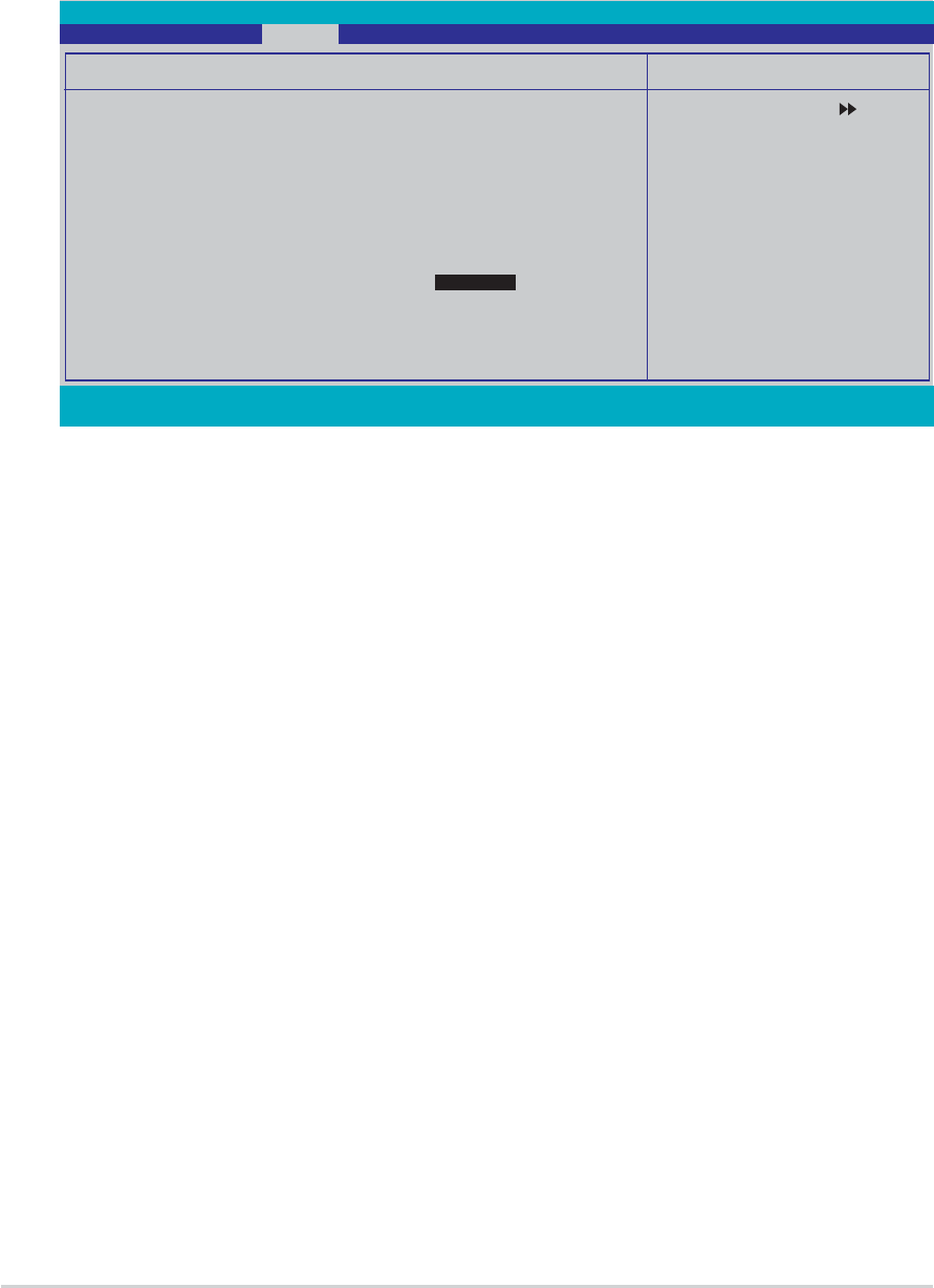
4.4.64.4.6
4.4.64.4.6
4.4.6 JumperFree ConfigurationJumperFree Configuration
JumperFree ConfigurationJumperFree Configuration
JumperFree Configuration
Overclock Profile [Auto]Overclock Profile [Auto]
Overclock Profile [Auto]Overclock Profile [Auto]
Overclock Profile [Auto]
Allows selection of CPU overclocking options to achieve desired CPU
internal frequency. Select either one of the preset overclocking
configuration options:
ManualManual
ManualManual
Manual Allows you to individually set overclocking
parameters.
AutoAuto
AutoAuto
Auto Loads the optimal settings for the system.
StandardStandard
StandardStandard
Standard Loads the standard settings for the system.
Overclock ProfileOverclock Profile
Overclock ProfileOverclock Profile
Overclock Profile Loads overclocking profiles with optimal
parameters for stability when overclocking.
AI N.O.S.AI N.O.S.
AI N.O.S.AI N.O.S.
AI N.O.S. The ASUS AI Non-delay Overclocking System
feature intelligently determines the system
load and automatically boost the performance
for the most demanding tasks.
F1:Help ↑↓ : Select Item -/+: Change Value F5: Setup Defaults
ESC: Exit →←: Select Menu Enter: Select Sub-menu F10: Save and Exit
Select Menu
Item Specific Help
JumperFree Configuration
Overclock Profile [Auto]
xOverclock Options Overclock 3%
xN.O.S. Option Overclock 3%
x Frequency Configuration
xCPU Multiplier Auto
xHammer Vid control Startup
xMemory Voltage Adjustment 2.70 V
x CPU Vcore Adjustment +100 mv
Phoenix-Award BIOS CMOS Setup Utility
Advanced
ASUS A8V-E DeluxeASUS A8V-E Deluxe
ASUS A8V-E DeluxeASUS A8V-E Deluxe
ASUS A8V-E Deluxe 4-274-27
4-274-27
4-27
The following items are user-configurable only when the AI Overclocking
item is set to [Manual].
F1:Help ↑↓ : Select Item -/+: Change Value F5: Setup Defaults
ESC: Exit →←: Select Menu Enter: Select Sub-menu F10: Save and Exit
Select Menu
Item Specific Help
JumperFree Configuration
Overclock Profile [Auto]
xOverclock Options Disabled
xN.O.S. Option Disabled
Frequency Configuration
CPU Multiplier [Auto]
Hammer Vid control [Startup]
Memory Voltage Adjustment [2.75 V]
CPU Vcore Adjustment [+100 mv]
Phoenix-Award BIOS CMOS Setup Utility
Advanced
F1:Help ↑↓ : Select Item -/+: Change Value F5: Setup Defaults
ESC: Exit →←: Select Menu Enter: Select Sub-menu F10: Save and Exit
Select Menu
Item Specific Help
Frequency Configuration
Spread Spectrum [Auto]
PCIEx clock Sync. to CPU [Enable]
xPCIEx Clock 100MHz
PCI clock Sync. to CPU [Enabled]
xPCI Clock 33.0 MHz
CPU Clock [200MHz]
Phoenix-Award BIOS CMOS Setup Utility
Advanced
Spread Spectrum [Auto]
Enables or disables the clock generator spread spectrum.
Configuration options: [Disabled] [Enabled] [Auto]
Frequency ConfigurationFrequency Configuration
Frequency ConfigurationFrequency Configuration
Frequency Configuration
The items in this sub-menu show the frequency information auto-detected
by the BIOS.

4-284-28
4-284-28
4-28 Chapter 4: BIOS setupChapter 4: BIOS setup
Chapter 4: BIOS setupChapter 4: BIOS setup
Chapter 4: BIOS setup
Selecting a very high CPU frequency may cause the system to become
unstable! If this happens, revert to the default setting.
PCIEx clock Sync. to CPU [Enable]
Enables or disables the PCI Express™ synchronous clock to the CPU.
Configuration options: [Disabled] [Enabled]
PCIEx Clock [XXX] (value is auto-detected)
Allows you to set the PCI Express clock frequency. This item is
user-configurable only when the PCIEx clock Sync. to CPUPCIEx clock Sync. to CPU
PCIEx clock Sync. to CPUPCIEx clock Sync. to CPU
PCIEx clock Sync. to CPU item is
set to Disabled. The BIOS detects the default value of this item. Press
<Enter> then key-in desired PCI Express clock frequency within range.
PCI clock Sync. to CPU [Enable]
Enables or disables the PCI synchronous clock to the CPU.
Configuration options: [Disabled] [Enabled]
PCI Clock [XXX] (value is auto-detected)
Allows you to set the PCI clock frequency. This item is
user-configurable only when the PCI clock Sync. to CPUPCI clock Sync. to CPU
PCI clock Sync. to CPUPCI clock Sync. to CPU
PCI clock Sync. to CPU item is
set to Disabled. The BIOS detects the default value of this item. Press
<Enter> then key-in desired PCI clock frequency within range.
CPU Clock [XXX] (value is auto-detected)
Displays the frequency sent by the clock generator to the system bus
and PCI bus. The default value of this item is auto-detected by the
BIOS. Use the <+> and <-> keys to adjust the CPU frequency. Refer to
the following table for the correct Front Side Bus and CPU External
Frequency settings.
CPU Multiplier [Auto]CPU Multiplier [Auto]
CPU Multiplier [Auto]CPU Multiplier [Auto]
CPU Multiplier [Auto]
Sets the CPU multiplier. Configuration options: [Auto] [x4] [x4.5] [x5]
[x5.5] [x6] [x6.5] [x7] [x7.5] [x8] [x8.5] [x9] [x9.5] [x10] [x10.5] [x11]
[x11.5] [x12] [x12.5] [x13] [x13.5] [x14] [x14.5] [x15] [x15.5] [x16]
[x16.5] [x17] [x17.5] [x18] [x18.5] [x19] [x19.5] [x20]

ASUS A8V-E DeluxeASUS A8V-E Deluxe
ASUS A8V-E DeluxeASUS A8V-E Deluxe
ASUS A8V-E Deluxe 4-294-29
4-294-29
4-29
Overclock Options [Overclock 3%]Overclock Options [Overclock 3%]
Overclock Options [Overclock 3%]Overclock Options [Overclock 3%]
Overclock Options [Overclock 3%]
Allows you to set the oveclocking options.
Configuration options: [Overclock 3%] [Overclock 5%] [Overclock 8%]
[Overclock 10%]
The following item is user-configurable only when the AI Overclocking
item is set to [AI Overclock].
Hammer Vid control [Startup]Hammer Vid control [Startup]
Hammer Vid control [Startup]Hammer Vid control [Startup]
Hammer Vid control [Startup]
Sets the Hammer Voltage ID control. Configuration options: [Startup]
[1.5625v] [1.550 v] [1.5375v] [1.525 v] [1.5125v] [1.500 v] [1.4875v]
[1.475 v] [1.4625v] [1.450 v] [1.4375v] [1.425 v] [1.4125v] [1.400 v]
[1.3875v] [1.375 v] [1.3625v] [1.350 v] [1.3375v] [1.325 v] [1.3125v]
[1.300 v] [1.2875v] [1.275 v] [1.2625v] [1.250 v] [1.2375v] [1.225 v]
[1.2125v] [1.200 v] [1.1875v] [1.175 v] [1.1625v] [1.150 v] [1.1375v]
[1.125 v] [1.1125v] [1.100 v] [1.0875v] [1.075 v] [1.0625v] [1.050 v]
[1.0375v] [1.025 v] [1.0125v] [1.000 v] [0.9875v] [0.975 v] [0.9625v]
[0.950 v] [0.9375v] [0.925 v] [0.9125v] [0.900 v] [0.8875v] [0.875 v]
[0.8625v] [0.850 v] [0.8375v] [0.825 v] [0.8125v] [0.800 v]
Memory Voltage Adjustment [2.75 V]Memory Voltage Adjustment [2.75 V]
Memory Voltage Adjustment [2.75 V]Memory Voltage Adjustment [2.75 V]
Memory Voltage Adjustment [2.75 V]
Sets the memory adjustment voltage. Configuration options: [2.60 V]
[2.65 V] [2.70 V] [2.75 V] [2.80 V] [2.85 V] [2.90 V] [2.95 V] [3.00 V]
CPU VCore Offset [+100 mv]CPU VCore Offset [+100 mv]
CPU VCore Offset [+100 mv]CPU VCore Offset [+100 mv]
CPU VCore Offset [+100 mv]
Sets the CPU Vcore offset voltage.
Configuration options: [+100 mv] [+200 mv]
The following item is user-configurable only when the AI Overclocking
item is set to [AI N.O.S.].
N.O.S. Option [Disable]N.O.S. Option [Disable]
N.O.S. Option [Disable]N.O.S. Option [Disable]
N.O.S. Option [Disable]
Allows you to disable or set the Non-Delay Overclocking System mode.
Configuration options: [Disable] [Overclock 3%] [Overclock 5%]
[Overclock 8%] [Overclock 10%]
4-304-30
4-304-30
4-30 Chapter 4: BIOS setupChapter 4: BIOS setup
Chapter 4: BIOS setupChapter 4: BIOS setup
Chapter 4: BIOS setup
4.4.84.4.8
4.4.84.4.8
4.4.8 PEG Link ModePEG Link Mode
PEG Link ModePEG Link Mode
PEG Link Mode
F1:Help ↑↓ : Select Item -/+: Change Value F5: Setup Defaults
ESC: Exit →←: Select Menu Enter: Select Sub-menu F10: Save and Exit
Select Menu
Item Specific Help
Enhance performance on
NVidia 6x00 PCIE
serial graphic card.
JumperFree Configuration
PEG Link Mode [Auto]
Phoenix-Award BIOS CMOS Setup Utility
Advanced
PEG Link Mode [Auto]PEG Link Mode [Auto]
PEG Link Mode [Auto]PEG Link Mode [Auto]
PEG Link Mode [Auto]
Allows you to enhance the performance of your PCI Express graphics card.
Configuration options: [Auto] [Slow] [Normal] [Fast] [Faster]
POST Check LAN cable [Disabled]POST Check LAN cable [Disabled]
POST Check LAN cable [Disabled]POST Check LAN cable [Disabled]
POST Check LAN cable [Disabled]
Enables or disables checking of the LAN cable during the Power-On
Self-Test (POST). Configuration options: [Disabled] [Enabled]
4.4.74.4.7
4.4.74.4.7
4.4.7 LAN Cable StatusLAN Cable Status
LAN Cable StatusLAN Cable Status
LAN Cable Status
The items in this menu displays the status of the Local Area Network
(LAN) cable.
F1:Help ↑↓ : Select Item -/+: Change Value F5: Setup Defaults
ESC: Exit →←: Select Menu Enter: Select Sub-menu F10: Save and Exit
Select Menu
Item Specific Help
Enable/Disable Speech
IC Controller
JumperFree Configuration
POST Check LAN Cable [Disabled]
Pair Status Length
1-2 Open N/A
3-6 Open N/A
4-5 Open N/A
7-8 Open N/A
Phoenix-Award BIOS CMOS Setup Utility
Advanced
ASUS A8V-E DeluxeASUS A8V-E Deluxe
ASUS A8V-E DeluxeASUS A8V-E Deluxe
ASUS A8V-E Deluxe 4-314-31
4-314-31
4-31
Speech IC Reporter [Enabled]Speech IC Reporter [Enabled]
Speech IC Reporter [Enabled]Speech IC Reporter [Enabled]
Speech IC Reporter [Enabled]
Allows you to enable or disable the ASUS Speech POST Reporter™ feature.
Configuration options: [Disabled] [Enabled]
The following items appear only when Speech POST Reporter is set to
Enabled.
Report IDE Error [Disabled]Report IDE Error [Disabled]
Report IDE Error [Disabled]Report IDE Error [Disabled]
Report IDE Error [Disabled]
Enables or disables the report feature in the event of an IDE error.
Configuration options: [Disabled] [Enabled]
Report System Booting [Disabled]Report System Booting [Disabled]
Report System Booting [Disabled]Report System Booting [Disabled]
Report System Booting [Disabled]
Enables or disables the report after booting the system.
Configuration options: [Disabled] [Enabled]
4.4.94.4.9
4.4.94.4.9
4.4.9 Speech ConfigurationSpeech Configuration
Speech ConfigurationSpeech Configuration
Speech Configuration
F1:Help ↑↓ : Select Item -/+: Change Value F5: Setup Defaults
ESC: Exit →←: Select Menu Enter: Select Sub-menu F10: Save and Exit
Select Menu
Item Specific Help
Enable/Disable Speech
IC Controller
JumperFree Configuration
Speech IC Reporter [Enabled]
Report IDE Error [Disabled]
Report System Booting [Disabled]
Phoenix-Award BIOS CMOS Setup Utility
Advanced
4-324-32
4-324-32
4-32 Chapter 4: BIOS setupChapter 4: BIOS setup
Chapter 4: BIOS setupChapter 4: BIOS setup
Chapter 4: BIOS setup
Instant Music [Disabled]Instant Music [Disabled]
Instant Music [Disabled]Instant Music [Disabled]
Instant Music [Disabled]
Allows you to enable or disable the ASUS Instant Music feature.
Configuration options: [Disabled] [Enabled]
Instant Music CD-ROM Drive [Primary Master]Instant Music CD-ROM Drive [Primary Master]
Instant Music CD-ROM Drive [Primary Master]Instant Music CD-ROM Drive [Primary Master]
Instant Music CD-ROM Drive [Primary Master]
Allows you to select the CD-ROM drive that you wish to use for the Instant
Music CD playback. Configuration options: [Primary Master] [Primary Slave]
[Secondary Master] [Secondary Slave]
4.4.104.4.10
4.4.104.4.10
4.4.10 Instant MusicInstant Music
Instant MusicInstant Music
Instant Music
F1:Help ↑↓ : Select Item -/+: Change Value F5: Setup Defaults
ESC: Exit →←: Select Menu Enter: Select Sub-menu F10: Save and Exit
Select Menu
Item Specific Help
If enabled, power up
by PS/2 keyboard
function will be
disabled.
JumperFree Configuration
Instant Music [Disabled]
xInstant Music CD-ROM Drive Primary Master
Phoenix-Award BIOS CMOS Setup Utility
Advanced
Enabling Instant Music automatically disables the PS/2 keyboard power
up feature.

ASUS A8V-E DeluxeASUS A8V-E Deluxe
ASUS A8V-E DeluxeASUS A8V-E Deluxe
ASUS A8V-E Deluxe 4-334-33
4-334-33
4-33
4.5 Power menu
The Power menu items allow you to change the settings for the Advanced
Configuration and Power Interface (ACPI) and the Advanced Power
Management (APM). Select an item then press <Enter> to display the
configuration options.
Phoenix-Award BIOS CMOS Setup Utility
Main Advanced Power Boot Exit
Select Menu
Item Specific Help
Select the ACPI state
used for System
Suspend.
ACPI Suspend Type [S1&S3]
ACPI APIC support [Enabled]
APM Configuration
Hardware Monitor
F1:Help ↑↓ : Select Item -/+: Change Value F5: Setup Defaults
ESC: Exit →←: Select Menu Enter: Select Sub-menu F10: Save and Exit
4.5.14.5.1
4.5.14.5.1
4.5.1 ACPI Suspend Type [S1&S3]ACPI Suspend Type [S1&S3]
ACPI Suspend Type [S1&S3]ACPI Suspend Type [S1&S3]
ACPI Suspend Type [S1&S3]
Allows you to select the Advanced Configuration and Power Interface
(ACPI) state to be used for system suspend.
Configuration options: [S1 (POS)] [S3(STR)] [S1&S3]
4.5.24.5.2
4.5.24.5.2
4.5.2 ACPI APIC Support [Enabled]ACPI APIC Support [Enabled]
ACPI APIC Support [Enabled]ACPI APIC Support [Enabled]
ACPI APIC Support [Enabled]
Allows you to enable or disable the Advanced Configuration and Power
Interface (ACPI) support in the Application-Specific Integrated Circuit
(ASIC). When set to Enabled, the ACPI APIC table pointer is included in the
RSDT pointer list. Configuration options: [Disabled] [Enabled]

4-344-34
4-344-34
4-34 Chapter 4: BIOS setupChapter 4: BIOS setup
Chapter 4: BIOS setupChapter 4: BIOS setup
Chapter 4: BIOS setup
4.5.34.5.3
4.5.34.5.3
4.5.3 APM ConfigurationAPM Configuration
APM ConfigurationAPM Configuration
APM Configuration
F1:Help ↑↓ : Select Item -/+: Change Value F5: Setup Defaults
ESC: Exit →←: Select Menu Enter: Select Sub-menu F10: Save and Exit
Select Menu
Item Specific Help
When Select Password,
Please press ENTER key
to change Password
Max 8 numbers.
APM Configuration
PS2KB Wakeup from S5 [Disabled]
PS2MS Wakeup from S5 [Disabled]
USB Resume from S3 [Disabled]
Power Up On PCI Devices [Disabled]
Modem Ring Resume [Disabled]
Power On By RTC Alarm [Disabled]
xDate (of Month) 0
xResume Time (hh:mm:ss) 0 : 0 : 0
Restore on AC Power Loss [Power Off]
PWR Button < 4 secs [Instant Off]
Phoenix-Award BIOS CMOS Setup Utility
Power
PS2KB Wakeup from S5 [Disabled]PS2KB Wakeup from S5 [Disabled]
PS2KB Wakeup from S5 [Disabled]PS2KB Wakeup from S5 [Disabled]
PS2KB Wakeup from S5 [Disabled]
Allows you to disable the Power On by PS/2 keyboard function or set
specific keys on the PS/2 keyboard to turn on the system. This feature
requires an ATX power supply that provides at least 1A on the +5VSB lead.
Configuration options: [Disabled] [Space Bar] [Ctrl+ESC] [Power Key]
PS2MS Wakeup from S5 [Disabled]PS2MS Wakeup from S5 [Disabled]
PS2MS Wakeup from S5 [Disabled]PS2MS Wakeup from S5 [Disabled]
PS2MS Wakeup from S5 [Disabled]
When set to [Enabled], this parameter allows you to use the PS/2 mouse
to turn on the system. This feature requires an ATX power supply that
provides at least 1A on the +5VSB lead. Configuration options: [Disabled]
[Enabled]
Power Up On PCI Devices [Disabled]Power Up On PCI Devices [Disabled]
Power Up On PCI Devices [Disabled]Power Up On PCI Devices [Disabled]
Power Up On PCI Devices [Disabled]
When set to [Enabled], this parameter allows you to turn on the system
through a PCI LAN or modem card. This feature requires an ATX power
supply that provides at least 1A on the +5VSB lead.
Configuration options: [Disabled] [Enabled]
Modem Ring Resume [Disabled]Modem Ring Resume [Disabled]
Modem Ring Resume [Disabled]Modem Ring Resume [Disabled]
Modem Ring Resume [Disabled]
This allows either settings of [Enabled] or [Disabled] for powering up the
computer when the external modem receives a call while the computer is in
Soft-off mode. Configuration options: [Disabled] [Enabled]

ASUS A8V-E DeluxeASUS A8V-E Deluxe
ASUS A8V-E DeluxeASUS A8V-E Deluxe
ASUS A8V-E Deluxe 4-354-35
4-354-35
4-35
Power On By RTC Alarm [Disabled]Power On By RTC Alarm [Disabled]
Power On By RTC Alarm [Disabled]Power On By RTC Alarm [Disabled]
Power On By RTC Alarm [Disabled]
Allows you to enable or disable RTC to generate a wake event. When this
item is set to Enabled, the items Date (of Month) and Resume Time
(hh:mm:ss) become configurable with set values.
Configuration options: [Disabled] [Enabled]
Date (of Month) [0]Date (of Month) [0]
Date (of Month) [0]Date (of Month) [0]
Date (of Month) [0]
To set the date of alarm, highlight this item and press <Enter> to display
the Day of Month Alarm pop-up menu. Key-in a value within the specified
range then press <Enter>. Configuration options: [Min=0] [Max=31]
Resume Time (hh:mm:ss) 0 : 0 : 0Resume Time (hh:mm:ss) 0 : 0 : 0
Resume Time (hh:mm:ss) 0 : 0 : 0Resume Time (hh:mm:ss) 0 : 0 : 0
Resume Time (hh:mm:ss) 0 : 0 : 0
To set the time of alarm:
1. Highlight this item and press <Enter> to display a pop-up menu for the
hour field.
2. Key-in a value (Min=0, Max=23), then press <Enter>.
3. Press <TAB> to move to the minutes field then press <Enter>.
4. Key-in a minute value (Min=0, Max=59), then press <Enter>.
5. Press <TAB> to move to the seconds field then press <Enter>.
6. Key-in a value (Min=0, Max=59), then press <Enter>.
Restore on AC Power Loss [Power Off]Restore on AC Power Loss [Power Off]
Restore on AC Power Loss [Power Off]Restore on AC Power Loss [Power Off]
Restore on AC Power Loss [Power Off]
When set to Power Off, the system goes into off state after an AC power
loss. When set to Power On, the system goes on after an AC power loss.
When set to Last State, the system goes into either off or on state,
whatever the system state was before the AC power loss.
Configuration options: [Power Off] [Power On] [Last State]
PWR Button < 4 secs [Instant-Off]PWR Button < 4 secs [Instant-Off]
PWR Button < 4 secs [Instant-Off]PWR Button < 4 secs [Instant-Off]
PWR Button < 4 secs [Instant-Off]
Allows you to set the event after the power button is pressed for more
than 4 seconds. Configuration options: [Suspend] [Instant-Off]
4-364-36
4-364-36
4-36 Chapter 4: BIOS setupChapter 4: BIOS setup
Chapter 4: BIOS setupChapter 4: BIOS setup
Chapter 4: BIOS setup
4.5.44.5.4
4.5.44.5.4
4.5.4 Hardware MonitorHardware Monitor
Hardware MonitorHardware Monitor
Hardware Monitor
The items in this sub-menu displays the hardware monitor values
automatically detected by the BIOS. It also allows you to change CPU Q-Fan
feature-related parameters. Select an item then press <Enter> to display
the configuration options.
F1:Help ↑↓ : Select Item -/+: Change Value F5: Setup Defaults
ESC: Exit →←: Select Menu Enter: Select Sub-menu F10: Save and Exit
Select Menu
Item Specific Help
Hardware Monitor
M/B Temperature 34ºC/ 93ºF
Current CPU1 Temperature 47ºC/118ºF
Chassis Fan speed 0 RPM
CPU Fan speed 4265 RPM
Chipset Fan speed 7500 RPM
Chassis Fan2 speed 6367 RPM
VCORE Voltage 1.64V
+12V Voltage 11.35V
+3.3V Voltage 3.36V
+5VCC Voltage 5.22V
Q-FAN Function [Disabled]
xCPU Target Temperature 45ºC/113ºF
xTemperature Tolerance 3ºC
xMinimum FAN Duty Cycle 11/16
xFAN Step Time 0.1 sec
Phoenix-Award BIOS CMOS Setup Utility
Power
M/B TemperatureM/B Temperature
M/B TemperatureM/B Temperature
M/B Temperature
Current CPU1 TemperatureCurrent CPU1 Temperature
Current CPU1 TemperatureCurrent CPU1 Temperature
Current CPU1 Temperature
The onboard hardware monitor automatically detects and displays the
motherboard and CPU temperatures. These items are not user-configurable.
Chassis Fan SpeedChassis Fan Speed
Chassis Fan SpeedChassis Fan Speed
Chassis Fan Speed
CPU Fan SpeedCPU Fan Speed
CPU Fan SpeedCPU Fan Speed
CPU Fan Speed
Chipset Fan SpeedChipset Fan Speed
Chipset Fan SpeedChipset Fan Speed
Chipset Fan Speed
Chassis Fan2 SpeedChassis Fan2 Speed
Chassis Fan2 SpeedChassis Fan2 Speed
Chassis Fan2 Speed
The onboard hardware monitor automatically detects and displays the
Chassis, CPU, and Power fan speeds in rotations per minute (RPM). If the
fan is not connected to the motherboard, the field shows 0. These items
are not user-configurable.
VCORE Voltage, +12V Voltage, 3.3V Voltage, 5VCCVCORE Voltage, +12V Voltage, 3.3V Voltage, 5VCC
VCORE Voltage, +12V Voltage, 3.3V Voltage, 5VCCVCORE Voltage, +12V Voltage, 3.3V Voltage, 5VCC
VCORE Voltage, +12V Voltage, 3.3V Voltage, 5VCC
VoltageVoltage
VoltageVoltage
Voltage
The onboard hardware monitor automatically detects the voltage output
through the onboard voltage regulators. These items are not
user-configurable.
Q-FAN Function [Disabled]Q-FAN Function [Disabled]
Q-FAN Function [Disabled]Q-FAN Function [Disabled]
Q-FAN Function [Disabled]
Allows you to disable or enable the ASUS Q-Fan function.
Configuration options: [Disabled] [Enabled]
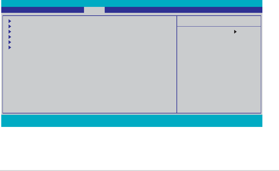
ASUS A8V-E DeluxeASUS A8V-E Deluxe
ASUS A8V-E DeluxeASUS A8V-E Deluxe
ASUS A8V-E Deluxe 4-374-37
4-374-37
4-37
CPU Target Temperature [xxxºC/xxxºF]CPU Target Temperature [xxxºC/xxxºF]
CPU Target Temperature [xxxºC/xxxºF]CPU Target Temperature [xxxºC/xxxºF]
CPU Target Temperature [xxxºC/xxxºF]
Allows you to set the CPU Q-Fan temperature threshold when the CPU fan
speed is increased to lower the CPU temperature.
Configuration options: [10ºC/50ºF] [15ºC/59ºF] [20ºC/68ºF] [25ºC/77ºF]
[30ºC/86ºF] [35ºC/95ºF] [40ºC/104ºF] [45ºC/113ºF] [50ºC/122ºF]
[55ºC/131ºF] [60ºC/140ºF] [65ºC/149ºF] [70ºC/158ºF] [75ºC/167ºF]
[80ºC/176ºF] [85ºC/185ºF]
Temperature Tolerance [3ºC]Temperature Tolerance [3ºC]
Temperature Tolerance [3ºC]Temperature Tolerance [3ºC]
Temperature Tolerance [3ºC]
Allows you to set the CPU temperature tolerance value.
Configuration options: [0ºC] [1ºC] [2ºC] [3ºC] [4ºC] [5ºC] [6ºC] [7ºC]
Minimum FAN Duty Cycle [11/16]Minimum FAN Duty Cycle [11/16]
Minimum FAN Duty Cycle [11/16]Minimum FAN Duty Cycle [11/16]
Minimum FAN Duty Cycle [11/16]
Allows you to set the minimum fan duty cycle.
Configuration options: [11/16] [12/16] [13/16] [14/16] [15/16]
FAN Step Time [0.1 sec]FAN Step Time [0.1 sec]
FAN Step Time [0.1 sec]FAN Step Time [0.1 sec]
FAN Step Time [0.1 sec]
Allows you to select the fan speed time interval. Configuration options:
[0.1 sec] [0.2 sec] [0.3 sec] [0.4 sec] [0.5 sec] [0.6 sec] [0.7 sec]
[0.8 sec] [0.9 sec] [1.0 sec] [1.1 sec] [1.2 sec] [1.3 sec] [1.4 sec]
[1.5 sec] [1.6 sec]
4.6 Boot menu
The Boot menu items allow you to change the system boot options. Select
an item then press <Enter> to display the sub-menu.
Phoenix-Award BIOS CMOS Setup Utility
Main Advanced Power Boot Exit
Select Menu
Item Specific Help
Boot Device Priority
Removable Drives
Hard Disk Drives
CDROM Drives
Boot Settings Configuration
Security
F1:Help ↑↓ : Select Item -/+: Change Value F5: Setup Defaults
ESC: Exit →←: Select Menu Enter: Select Sub-menu F10: Save and Exit
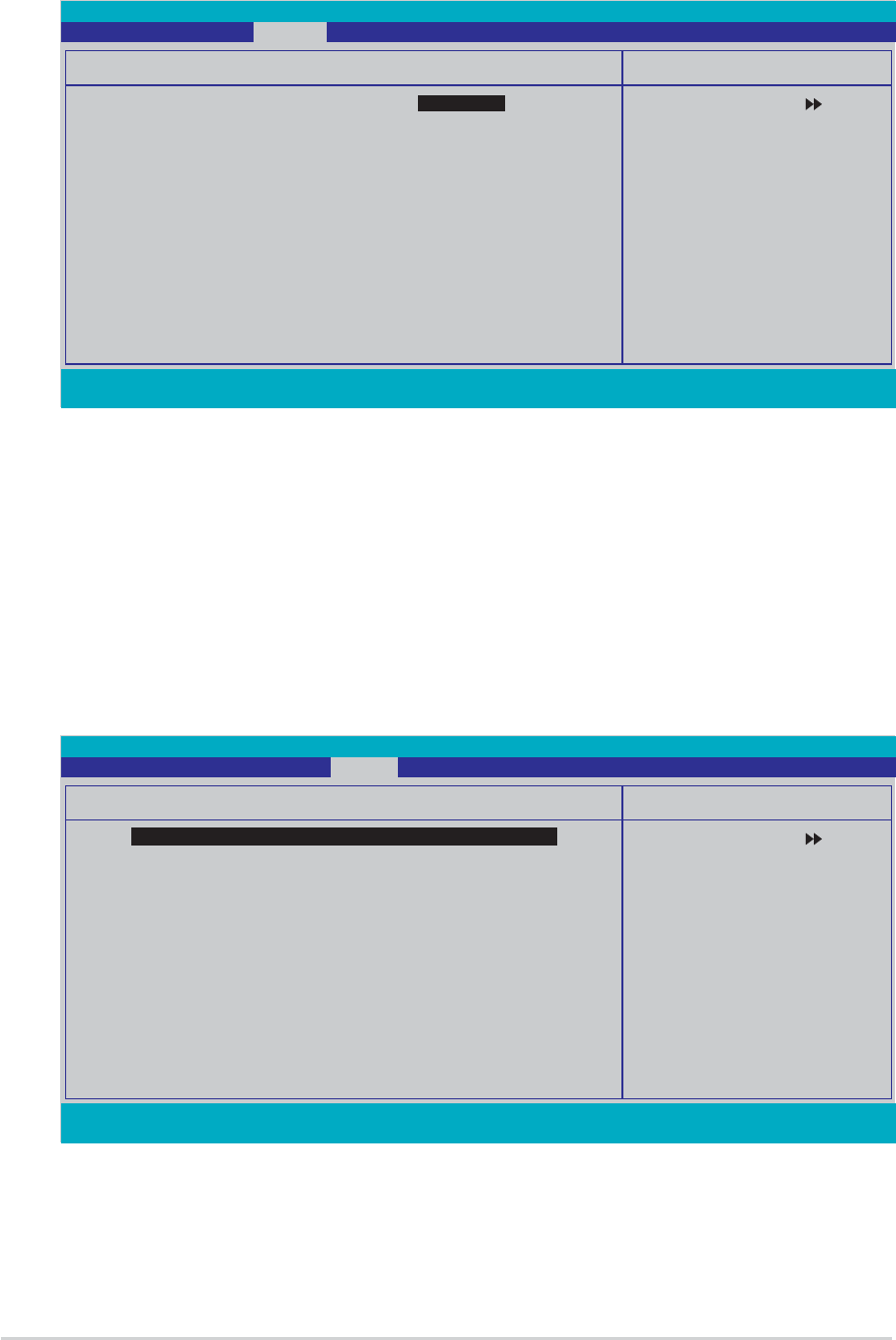
4-384-38
4-384-38
4-38 Chapter 4: BIOS setupChapter 4: BIOS setup
Chapter 4: BIOS setupChapter 4: BIOS setup
Chapter 4: BIOS setup
4.6.14.6.1
4.6.14.6.1
4.6.1 Boot Device PriorityBoot Device Priority
Boot Device PriorityBoot Device Priority
Boot Device Priority
1st ~ xxth Boot Device [Removable]1st ~ xxth Boot Device [Removable]
1st ~ xxth Boot Device [Removable]1st ~ xxth Boot Device [Removable]
1st ~ xxth Boot Device [Removable]
These items specify the boot device priority sequence from the available
devices. The number of device items that appears on the screen depends
on the number of devices installed in the system.
Configuration options: [xxxxx Drive] [Disabled]
F1:Help ↑↓ : Select Item -/+: Change Value F5: Setup Defaults
ESC: Exit →←: Select Menu Enter: Select Sub-menu F10: Save and Exit
Select Menu
Item Specific Help
Select your boot
device priority
Boot Device Priority
1st Boot Device [Removable]
2nd Boot Device [Hard Disk]
3rd Boot Device [CDROM]
4th Boot Device [Disabled]
Phoenix-Award BIOS CMOS Setup Utility
Power
4.6.24.6.2
4.6.24.6.2
4.6.2 Removable DrivesRemovable Drives
Removable DrivesRemovable Drives
Removable Drives
1. Floppy Disks1. Floppy Disks
1. Floppy Disks1. Floppy Disks
1. Floppy Disks
Allows you to assign a removable drive attached to the system.
F1:Help ↑↓ : Select Item -/+: Change Value F5: Setup Defaults
ESC: Exit →←: Select Menu Enter: Select Sub-menu F10: Save and Exit
Select Menu
Item Specific Help
Use <↑> or <↓> to
select a device, then
press <+> to move it
up, or <-> to move it
down the list. Press
<ESC> to exit this
menu.
Removable Drives
1. Floppy Disks
Phoenix-Award BIOS CMOS Setup Utility
Boot
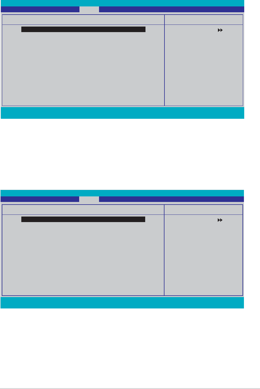
ASUS A8V-E DeluxeASUS A8V-E Deluxe
ASUS A8V-E DeluxeASUS A8V-E Deluxe
ASUS A8V-E Deluxe 4-394-39
4-394-39
4-39
4.6.34.6.3
4.6.34.6.3
4.6.3 Hard Disk DrivesHard Disk Drives
Hard Disk DrivesHard Disk Drives
Hard Disk Drives
1. 1st Master: XXXXXXXXX1. 1st Master: XXXXXXXXX
1. 1st Master: XXXXXXXXX1. 1st Master: XXXXXXXXX
1. 1st Master: XXXXXXXXX
Allows you to assign hard disk drives attached to the system.
F1:Help ↑↓ : Select Item -/+: Change Value F5: Setup Defaults
ESC: Exit →←: Select Menu Enter: Select Sub-menu F10: Save and Exit
Select Menu
Item Specific Help
Use <↑> or <↓> to
select a device, then
press <+> to move it
up, or <-> to move it
down the list. Press
<ESC> to exit this
menu.
Hard Disk Drives
1. 1st Master: XXXXXXXXX
2. Bootable Add-in Cards
Phoenix-Award BIOS CMOS Setup Utility
Boot
4.6.44.6.4
4.6.44.6.4
4.6.4 CDROM DrivesCDROM Drives
CDROM DrivesCDROM Drives
CDROM Drives
1. 1st Slave: XXXXXXXXX1. 1st Slave: XXXXXXXXX
1. 1st Slave: XXXXXXXXX1. 1st Slave: XXXXXXXXX
1. 1st Slave: XXXXXXXXX
Allows you to assign optical drives attached to the system.
F1:Help ↑↓ : Select Item -/+: Change Value F5: Setup Defaults
ESC: Exit →←: Select Menu Enter: Select Sub-menu F10: Save and Exit
Select Menu
Item Specific Help
Use <↑> or <↓> to
select a device, then
press <+> to move it
up, or <-> to move it
down the list. Press
<ESC> to exit this
menu.
CDROM Drives
1. 1st Slave: XXXXXXXXX
Phoenix-Award BIOS CMOS Setup Utility
Boot

4-404-40
4-404-40
4-40 Chapter 4: BIOS setupChapter 4: BIOS setup
Chapter 4: BIOS setupChapter 4: BIOS setup
Chapter 4: BIOS setup
The items Typematic Rate (Chars/Sec)Typematic Rate (Chars/Sec)
Typematic Rate (Chars/Sec)Typematic Rate (Chars/Sec)
Typematic Rate (Chars/Sec) and Typematic DelayTypematic Delay
Typematic DelayTypematic Delay
Typematic Delay
(Msec)(Msec)
(Msec)(Msec)
(Msec) becomes user-configurable only when the item Typematic Rate
Setting is enabled.
4.6.54.6.5
4.6.54.6.5
4.6.5 Boot Settings ConfigurationBoot Settings Configuration
Boot Settings ConfigurationBoot Settings Configuration
Boot Settings Configuration
F1:Help ↑↓ : Select Item -/+: Change Value F5: Setup Defaults
ESC: Exit →←: Select Menu Enter: Select Sub-menu F10: Save and Exit
Select Menu
Item Specific Help
Press [Enter] to
enable or disable.
Boot Settings Configuration
Case Open Warning [Enabled]
Quick Boot [Enabled]
Boot Up Floppy Seek [Enabled]
Bootup Num-Lock [On]
Typematic Rate Setting [Disabled]
xTypematic Rate (Chars/Sec) 6
xTypematic Delay (Msec) 250
OS Select For DRAM > 64MB [Non-OS2]
Full Screen LOGO [Enabled]
Halt On [All, But Keyboard]
Phoenix-Award BIOS CMOS Setup Utility
Boot
Case Open Warning [Enabled]Case Open Warning [Enabled]
Case Open Warning [Enabled]Case Open Warning [Enabled]
Case Open Warning [Enabled]
Enables or disables the chassis open status feature. Setting to Enabled,
clears the chassis open status. Configuration options: [Disabled] [Enabled]
Quick Boot [Enabled]Quick Boot [Enabled]
Quick Boot [Enabled]Quick Boot [Enabled]
Quick Boot [Enabled]
Enables or disables the quick boot feature. When Enabled, the system skips
certain tests while booting. Configuration options: [Disabled] [Enabled]
Boot Up Floppy Seek [Enabled]Boot Up Floppy Seek [Enabled]
Boot Up Floppy Seek [Enabled]Boot Up Floppy Seek [Enabled]
Boot Up Floppy Seek [Enabled]
Enables or disables the chassis open status feature. Setting to Enabled,
clears the chassis open status. Configuration options: [Disabled] [Enabled]
Bootup Num-Lock [On]Bootup Num-Lock [On]
Bootup Num-Lock [On]Bootup Num-Lock [On]
Bootup Num-Lock [On]
Allows you to select the power-on state for the NumLock.
Configuration options: [Off] [On]
Typematic Rate Setting [Disabled]Typematic Rate Setting [Disabled]
Typematic Rate Setting [Disabled]Typematic Rate Setting [Disabled]
Typematic Rate Setting [Disabled]
Allows you to set the keystroke rate. Enable this item to configure the
Typematic Rate (Chars/Sec) Typematic Rate (Chars/Sec)
Typematic Rate (Chars/Sec) Typematic Rate (Chars/Sec)
Typematic Rate (Chars/Sec) and the Typematic Delay (Msec)Typematic Delay (Msec)
Typematic Delay (Msec)Typematic Delay (Msec)
Typematic Delay (Msec).
Configuration options: [Disabled] [Enabled]

ASUS A8V-E DeluxeASUS A8V-E Deluxe
ASUS A8V-E DeluxeASUS A8V-E Deluxe
ASUS A8V-E Deluxe 4-414-41
4-414-41
4-41
Typematic Rate (Chars/Sec) [6]Typematic Rate (Chars/Sec) [6]
Typematic Rate (Chars/Sec) [6]Typematic Rate (Chars/Sec) [6]
Typematic Rate (Chars/Sec) [6]
Allows you to select the rate at which a character repeats when you hold a
key. Configuration options: [6] [8] [10] [12] [15] [20] [24] [30]
Typematic Delay (Msec) [250]Typematic Delay (Msec) [250]
Typematic Delay (Msec) [250]Typematic Delay (Msec) [250]
Typematic Delay (Msec) [250]
Allows you to set the delay before keystrokes begin to repeat.
Configuration options: [250] [500] [750] [1000]
OS Select for DRAM > 64MB [Non-OS2]OS Select for DRAM > 64MB [Non-OS2]
OS Select for DRAM > 64MB [Non-OS2]OS Select for DRAM > 64MB [Non-OS2]
OS Select for DRAM > 64MB [Non-OS2]
Set this item to OS2 only when you are running on an OS/2 operating
system with an installed RAM of greater than 64 KB.
Configuration options: [Non-OS2] [OS2]
Full Screen LOGO [Enabled]Full Screen LOGO [Enabled]
Full Screen LOGO [Enabled]Full Screen LOGO [Enabled]
Full Screen LOGO [Enabled]
Allows you to enable or disable the full screen logo display feature.
Configuration options: [Disabled] [Enabled]
Make sure that the above item is set to [Enabled] if you want to use the
ASUS MyLogo2™ feature.
Halt On [All, But Keyboard]Halt On [All, But Keyboard]
Halt On [All, But Keyboard]Halt On [All, But Keyboard]
Halt On [All, But Keyboard]
Allows you to error report type.
Configuration options: [All Errors] [No Errors] [All, But Keyboard]
[All, But Diskette] [All, But Disk/Key]

4-424-42
4-424-42
4-42 Chapter 4: BIOS setupChapter 4: BIOS setup
Chapter 4: BIOS setupChapter 4: BIOS setup
Chapter 4: BIOS setup
4.6.64.6.6
4.6.64.6.6
4.6.6 SecuritySecurity
SecuritySecurity
Security
F1:Help ↑↓ : Select Item -/+: Change Value F5: Setup Defaults
ESC: Exit →←: Select Menu Enter: Select Sub-menu F10: Save and Exit
Select Menu
Item Specific Help
Supervisor password
controls full access,
<Enter> to change
password.
Boot Settings Configuration
Supervisor Password Clear
User Password Clear
Password Check [Setup]
Phoenix-Award BIOS CMOS Setup Utility
Boot
Supervisor PasswordSupervisor Password
Supervisor PasswordSupervisor Password
Supervisor Password
User PasswordUser Password
User PasswordUser Password
User Password
These fields allow you to set passwords:
To set a password:
1. Select an item then press <Enter>.
2. Type in a password using a combination of a maximum of eight (8)
alpha-numeric characters, then press <Enter>.
3. When prompted, confirm the password by typing the exact characters
again, then press <Enter>. The password field setting is changed to
Set.
To clear the password:
1. Select the password field and press <Enter> twice. The following
message appears:
PASSWORD DISABLED !!!
Press any key to continue...
2. Press any key to continue. The password field setting is changed to
Clear.

ASUS A8V-E DeluxeASUS A8V-E Deluxe
ASUS A8V-E DeluxeASUS A8V-E Deluxe
ASUS A8V-E Deluxe 4-434-43
4-434-43
4-43
A note about passwordsA note about passwords
A note about passwordsA note about passwords
A note about passwords
The Supervisor password is required to enter the BIOS Setup program
preventing unauthorized access. The User password is required to
boot the system preventing unauthorized use.
Forgot your password?Forgot your password?
Forgot your password?Forgot your password?
Forgot your password?
If you forget your password, you can clear it by erasing the CMOS Real
Time Clock (RTC) RAM. The RAM data containing the password
information is powered by the onboard button cell battery. If you need
to erase the CMOS RAM, refer to section “2.6 Jumpers” for
instructions.
Password CheckPassword Check
Password CheckPassword Check
Password Check
This field requires you to enter the password before entering the BIOS
setup or the system. Select [Setup] to require the password before
entering the BIOS Setup. Select [System] to require the password before
entering the system. Configuration options: [Setup] [System]
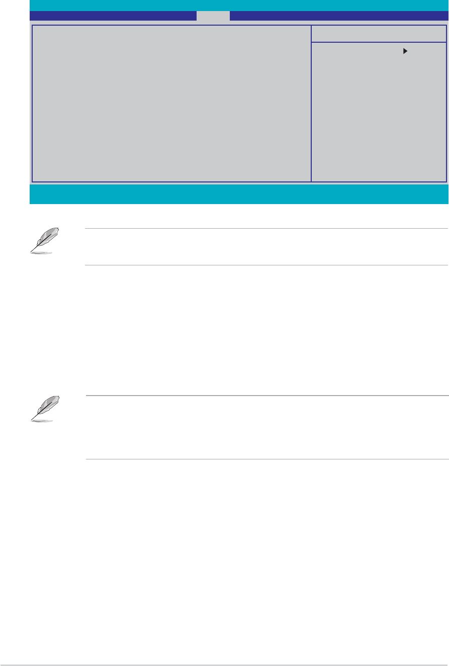
4-444-44
4-444-44
4-44 Chapter 4: BIOS setupChapter 4: BIOS setup
Chapter 4: BIOS setupChapter 4: BIOS setup
Chapter 4: BIOS setup
Phoenix-Award BIOS CMOS Setup Utility
Main Advanced Power Boot Exit
Select Menu
Item Specific Help
This option save data
to CMOS and exiting
the setup menu.
Exit & Save Changes
Exit & Discard Changes
Load Setup Default
Discard Changes
F1:Help ↑↓ : Select Item -/+: Change Value F5: Setup Defaults
ESC: Exit →←: Select Menu Enter: Select Sub-menu F10: Save and Exit
4.7 Exit menu
The Exit menu items allow you to load the optimal or failsafe default values
for the BIOS items, and save or discard your changes to the BIOS items.
Exit & Save ChangesExit & Save Changes
Exit & Save ChangesExit & Save Changes
Exit & Save Changes
Once you are finished making your selections, choose this option from the
Exit menu to ensure the values you selected are saved to the CMOS RAM.
An onboard backup battery sustains the CMOS RAM so it stays on even
when the PC is turned off. When you select this option, a confirmation
window appears. Select YesYes
YesYes
Yes to save changes and exit.
Pressing <Esc> does not immediately exit this menu. Select one of the
options from this menu or <F10> from the legend bar to exit.
Exit & Discard ChangesExit & Discard Changes
Exit & Discard ChangesExit & Discard Changes
Exit & Discard Changes
Select this option only if you do not want to save the changes that you
made to the Setup program. If you made changes to fields other than
System Date, System Time, and Password, the BIOS asks for a confirmation
before exiting.
If you attempt to exit the Setup program without saving your changes,
the program prompts you with a message asking if you want to save
your changes before exiting. Press <Enter> to save the changes while
exiting.

ASUS A8V-E DeluxeASUS A8V-E Deluxe
ASUS A8V-E DeluxeASUS A8V-E Deluxe
ASUS A8V-E Deluxe 4-454-45
4-454-45
4-45
Load Setup DefaultsLoad Setup Defaults
Load Setup DefaultsLoad Setup Defaults
Load Setup Defaults
This option allows you to load the default values for each of the
parameters on the Setup menus. When you select this option or if you
press <F5>, a confirmation window appears. Select YesYes
YesYes
Yes to load default
values. Select Exit & Save ChangesExit & Save Changes
Exit & Save ChangesExit & Save Changes
Exit & Save Changes or make other changes before
saving the values to the non-volatile RAM.
Discard ChangesDiscard Changes
Discard ChangesDiscard Changes
Discard Changes
This option allows you to discard the selections you made and restore the
previously saved values. After selecting this option, a confirmation appears.
Select YesYes
YesYes
Yes to discard any changes and load the previously saved values.

4-464-46
4-464-46
4-46 Chapter 4: BIOS setupChapter 4: BIOS setup
Chapter 4: BIOS setupChapter 4: BIOS setup
Chapter 4: BIOS setup
5
Software
support
This chapter describes the contents
of the support CD that comes with
the motherboard package.

ASUS A8V-E DeluxeASUS A8V-E Deluxe
ASUS A8V-E DeluxeASUS A8V-E Deluxe
ASUS A8V-E Deluxe
Chapter summary
5.1 Installing an operating system ............................................. 5-1
5.2 Support CD information ........................................................ 5-1
5.3 Software information ........................................................... 5-9
5.4 RAID configurations ............................................................ 5-18
5.5 Creating a RAID driver disk ................................................. 5-26
5.6 Cool ‘n’ Quiet!™ Technology ............................................... 5-27
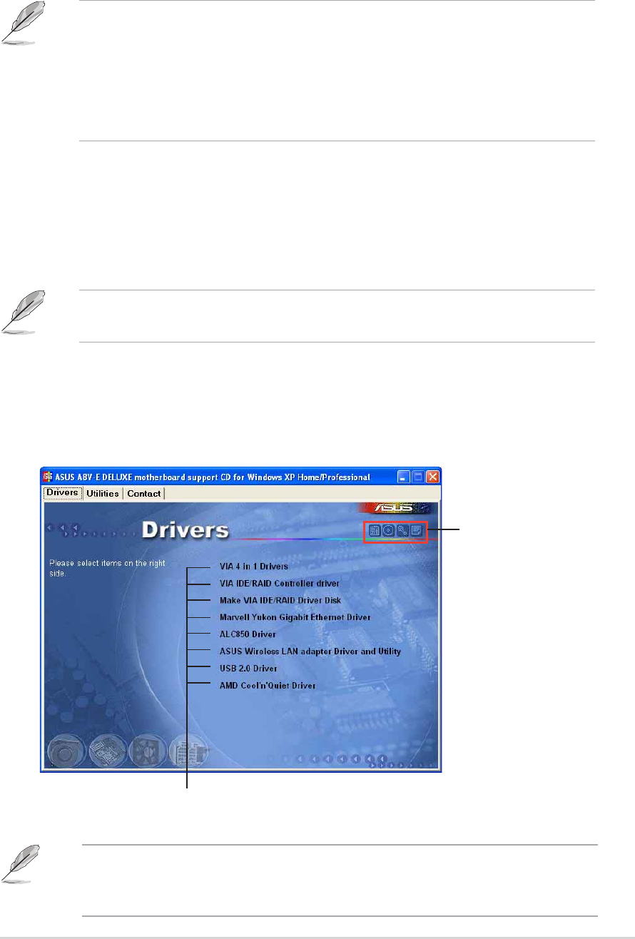
ASUS A8V-E DeluxeASUS A8V-E Deluxe
ASUS A8V-E DeluxeASUS A8V-E Deluxe
ASUS A8V-E Deluxe 5-15-1
5-15-1
5-1
If Autorun Autorun
Autorun Autorun
Autorun is NOT enabled in your computer, browse the contents of
the support CD to locate the file ASSETUP.EXE from the BIN folder.
Double-click the ASSETUP.EXEASSETUP.EXE
ASSETUP.EXEASSETUP.EXE
ASSETUP.EXE to run the CD.
Click an item to installClick an item to install
Click an item to installClick an item to install
Click an item to install
5.1 Installing an operating system
This motherboard supports Windows
®
2000/2003 Server/XP operating
systems (OS). Always install the latest OS version and corresponding
updates to maximize the features of your hardware.
5.2 Support CD information
The support CD that came with the motherboard package contains the
drivers, software applications, and utilities that you can install to avail all
motherboard features.
5.2.15.2.1
5.2.15.2.1
5.2.1 Running the support CDRunning the support CD
Running the support CDRunning the support CD
Running the support CD
Place the support CD to the optical drive. The CD automatically displays the
Drivers Drivers
Drivers Drivers
Drivers menu if Autorun is enabled in your computer.
•Motherboard settings and hardware options vary. Use the setup
procedures presented in this chapter for reference only. Refer to
your OS documentation for detailed information.
•Make sure that you install Windows
®
2000 Service Pack 4 or the
Windows
®
XP Service Pack1 or later versions before installing the
drivers for better compatibility and system stability.
The contents of the support CD are subject to change at any time
without notice. Visit the ASUS website(www.asus.com) for updates.
Click an icon toClick an icon to
Click an icon toClick an icon to
Click an icon to
display supportdisplay support
display supportdisplay support
display support
CD/motherboardCD/motherboard
CD/motherboardCD/motherboard
CD/motherboard
informationinformation
informationinformation
information

5-25-2
5-25-2
5-2 Chapter 5: Software supportChapter 5: Software support
Chapter 5: Software supportChapter 5: Software support
Chapter 5: Software support
5.2.25.2.2
5.2.25.2.2
5.2.2 Drivers menuDrivers menu
Drivers menuDrivers menu
Drivers menu
The drivers menu shows the available device drivers if the system detects
installed devices. Install the necessary drivers to activate the devices.
VIA 4 in 1 driversVIA 4 in 1 drivers
VIA 4 in 1 driversVIA 4 in 1 drivers
VIA 4 in 1 drivers
This item installs the following drivers:
- VIA Registry (INF) driver
- VIA ATAPI vendor support driver
- VIA PCI IRQ Miniport driver.
VIA IDE RAID Controller driverVIA IDE RAID Controller driver
VIA IDE RAID Controller driverVIA IDE RAID Controller driver
VIA IDE RAID Controller driver
Installs the VIA 6420 RAID controller driver and application.
Make VIA 6420 Driver DiskMake VIA 6420 Driver Disk
Make VIA 6420 Driver DiskMake VIA 6420 Driver Disk
Make VIA 6420 Driver Disk
Allows you to create a RAID driver disk for the VIA 6420 RAID
configuration.
PCI Marvell Yukon Gigabit Ethernet DriverPCI Marvell Yukon Gigabit Ethernet Driver
PCI Marvell Yukon Gigabit Ethernet DriverPCI Marvell Yukon Gigabit Ethernet Driver
PCI Marvell Yukon Gigabit Ethernet Driver
Installs the Marvell
®
Yukon 88E8053 PCI Express™ Gigabit LAN driver that
provides up to 1000 Mbps data transfer rates.
ALC850 Audio DriverALC850 Audio Driver
ALC850 Audio DriverALC850 Audio Driver
ALC850 Audio Driver
Installs the Realtek
®
ALC850 audio controller and application.

ASUS A8V-E DeluxeASUS A8V-E Deluxe
ASUS A8V-E DeluxeASUS A8V-E Deluxe
ASUS A8V-E Deluxe 5-35-3
5-35-3
5-3
ASUS Wireless LAN adapter Drivers and UtilityASUS Wireless LAN adapter Drivers and Utility
ASUS Wireless LAN adapter Drivers and UtilityASUS Wireless LAN adapter Drivers and Utility
ASUS Wireless LAN adapter Drivers and Utility
Installs the driver, utilities, and setup wizard for the ASUS WiFi-g™ wireless
solution. Refer to the WiFi-g™ documentation for details.
USB 2.0 DriverUSB 2.0 Driver
USB 2.0 DriverUSB 2.0 Driver
USB 2.0 Driver
Installs the USB 2.0 driver.
AMD Cool ‘n’ Quiet DriverAMD Cool ‘n’ Quiet Driver
AMD Cool ‘n’ Quiet DriverAMD Cool ‘n’ Quiet Driver
AMD Cool ‘n’ Quiet Driver
Launches the AMD Cool ‘n’ Quiet!™ Technology driver installation wizard.
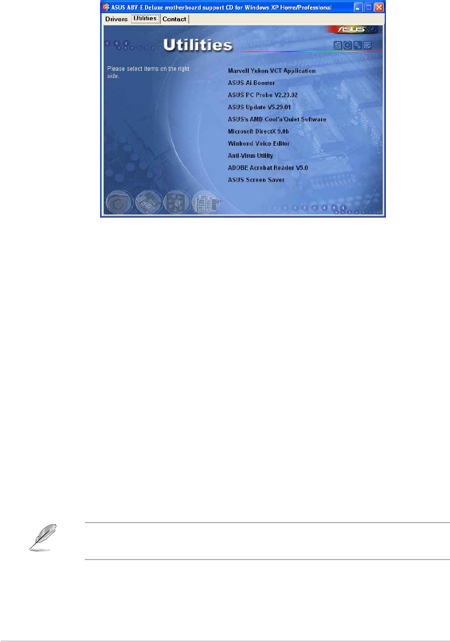
5-45-4
5-45-4
5-4 Chapter 5: Software supportChapter 5: Software support
Chapter 5: Software supportChapter 5: Software support
Chapter 5: Software support
5.2.35.2.3
5.2.35.2.3
5.2.3 Utilities menuUtilities menu
Utilities menuUtilities menu
Utilities menu
The Utilities menu shows the applications and other software that the
motherboard supports.
Marvell Yukon VCT ApplicationMarvell Yukon VCT Application
Marvell Yukon VCT ApplicationMarvell Yukon VCT Application
Marvell Yukon VCT Application
Installs the Marvell
®
Yukon Virtual Cable Tester (VCT) application. The VCT
is a cable diagnostic application that analyzes and reports LAN cable faults
and shorts. See page 5-11 for details.
AI BoosterAI Booster
AI BoosterAI Booster
AI Booster
The ASUS AI Booster application allows you to overclock the CPU speed in a
Windows
®
environment.
ASUS PC ProbeASUS PC Probe
ASUS PC ProbeASUS PC Probe
ASUS PC Probe
This smart utility monitors the fan speed, CPU temperature, and system
voltages, and alerts you of any detected problems. This utility helps you
keep your computer in healthy operating condition.
ASUS UpdateASUS Update
ASUS UpdateASUS Update
ASUS Update
Allows you to download the latest version of the BIOS from the ASUS
website.
Before using the ASUS Update, make sure that you have an Internet
connection so you can connect to the ASUS website.

ASUS A8V-E DeluxeASUS A8V-E Deluxe
ASUS A8V-E DeluxeASUS A8V-E Deluxe
ASUS A8V-E Deluxe 5-55-5
5-55-5
5-5
Microsoft DirectXMicrosoft DirectX
Microsoft DirectXMicrosoft DirectX
Microsoft DirectX
Installs the Microsoft
®
DirectX 9.0 driver. The Microsoft DirectX
®
9.0 is a
multimedia technology that enhances computer graphics and sound.
DirectX
®
improves the multimedia features of you computer so you can
enjoy watching TV and movies, capturing videos, or playing games in your
computer. Visit the Microsoft website (www.microsoft.com) for updates.
Winbond Voice EditorWinbond Voice Editor
Winbond Voice EditorWinbond Voice Editor
Winbond Voice Editor
This program is for recording and customizing wave files for the ASUS
POST Reporter™. Use this program to change the default vocal POST
messages. See section “3.3 Vocal POST Messages” for a list of the default
messages.
Anti-virus UtilityAnti-virus Utility
Anti-virus UtilityAnti-virus Utility
Anti-virus Utility
The anti-virus application detects and protects your computer from viruses
that destroys data.
ADOBE Acrobat ReaderADOBE Acrobat Reader
ADOBE Acrobat ReaderADOBE Acrobat Reader
ADOBE Acrobat Reader
Installs the Adobe
®
Acrobat
®
Reader that allows you to open, view, and
print documents in Portable Document Format (PDF).
ASUS Screen SaverASUS Screen Saver
ASUS Screen SaverASUS Screen Saver
ASUS Screen Saver
Bring life to your computer screen by installing the ASUS screen saver.
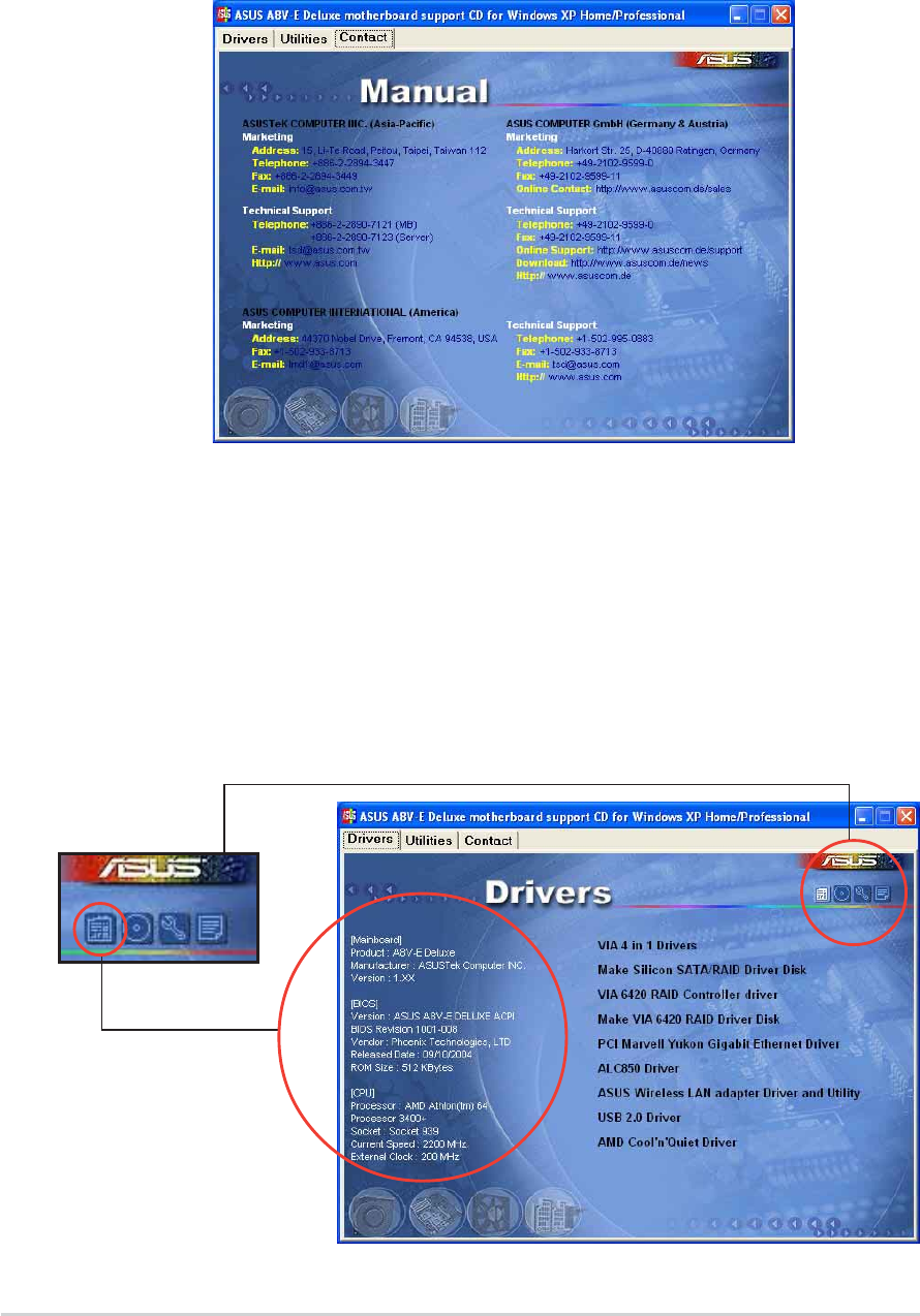
5-65-6
5-65-6
5-6 Chapter 5: Software supportChapter 5: Software support
Chapter 5: Software supportChapter 5: Software support
Chapter 5: Software support
5.2.45.2.4
5.2.45.2.4
5.2.4 ASUS Contact informationASUS Contact information
ASUS Contact informationASUS Contact information
ASUS Contact information
Click the Contact Contact
Contact Contact
Contact tab to display the ASUS contact information. You can
also find this information on the inside front cover of this user guide.
5.2.55.2.5
5.2.55.2.5
5.2.5 Other informationOther information
Other informationOther information
Other information
The icons on the top right corner of the screen give additional information
on the motherboard and the contents of the support CD. Click an icon to
display the specified information.
Motherboard InfoMotherboard Info
Motherboard InfoMotherboard Info
Motherboard Info
Displays the general specifications of the motherboard.
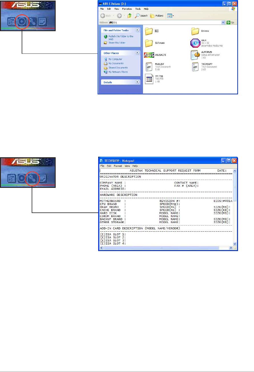
ASUS A8V-E DeluxeASUS A8V-E Deluxe
ASUS A8V-E DeluxeASUS A8V-E Deluxe
ASUS A8V-E Deluxe 5-75-7
5-75-7
5-7
Browse this CDBrowse this CD
Browse this CDBrowse this CD
Browse this CD
Displays the support CD contents in graphical format.
Technical support FormTechnical support Form
Technical support FormTechnical support Form
Technical support Form
Displays the ASUS Technical Support Request Form that you have to fill out
when requesting technical support.
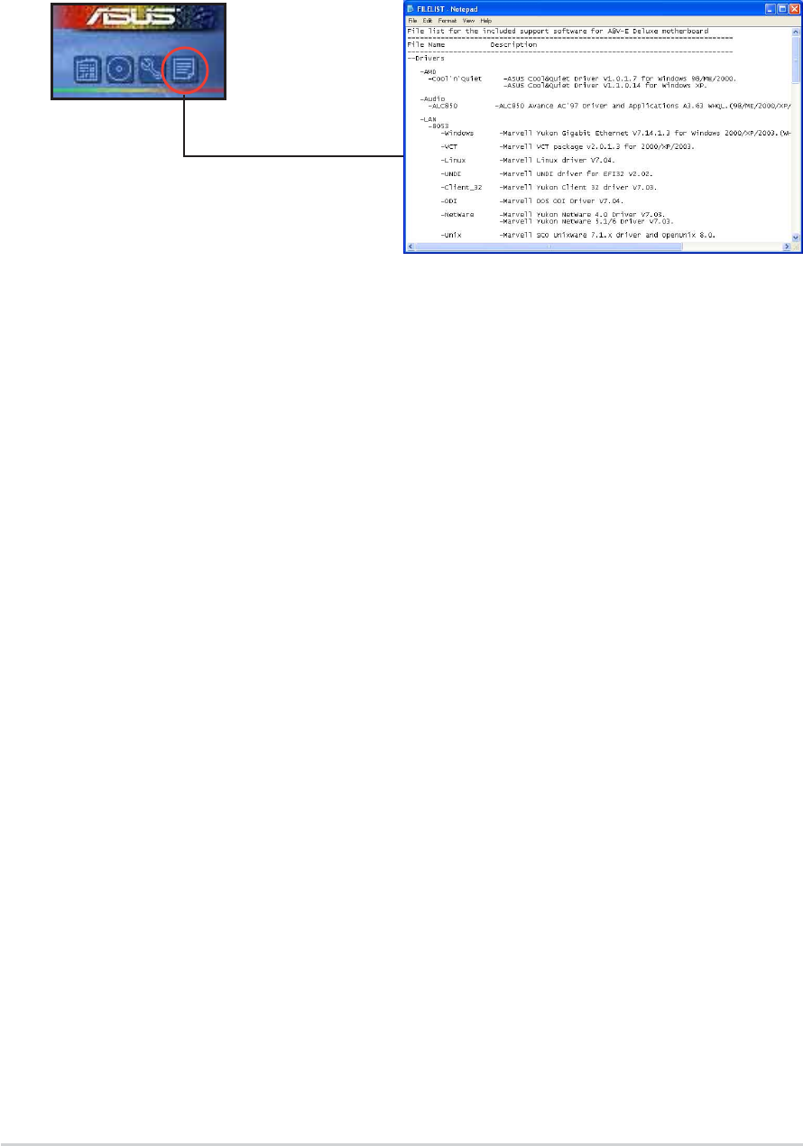
5-85-8
5-85-8
5-8 Chapter 5: Software supportChapter 5: Software support
Chapter 5: Software supportChapter 5: Software support
Chapter 5: Software support
FilelistFilelist
FilelistFilelist
Filelist
Displays the contents of the support CD and a brief description of each in
text format.
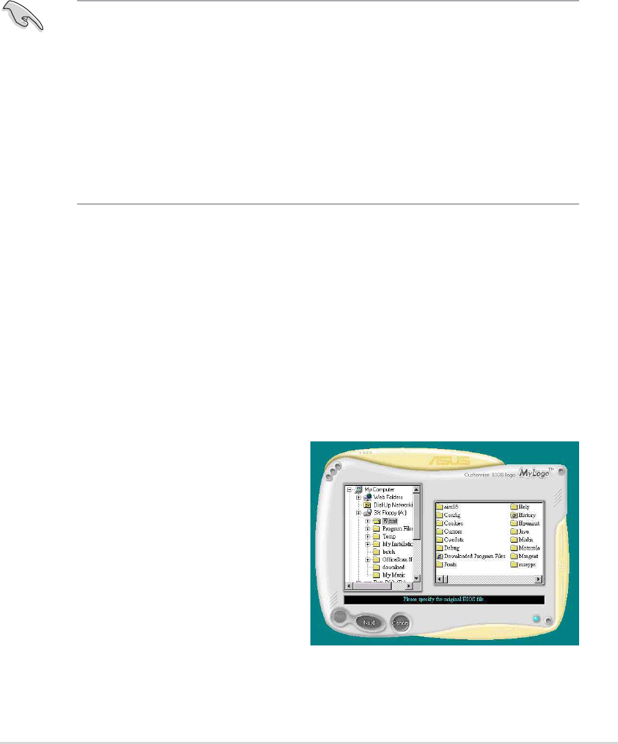
ASUS A8V-E DeluxeASUS A8V-E Deluxe
ASUS A8V-E DeluxeASUS A8V-E Deluxe
ASUS A8V-E Deluxe 5-95-9
5-95-9
5-9
5.3 Software information
Most of the applications in the support CD have wizards that will
conveniently guide you through the installation. View the online help or
readme file that came with the software application for more information.
5.3.15.3.1
5.3.15.3.1
5.3.1 ASUS MyLogo2™ASUS MyLogo2™
ASUS MyLogo2™ASUS MyLogo2™
ASUS MyLogo2™
The ASUS MyLogo2™ utility lets you customize the boot logo. The boot
logo is the image that appears on screen during the Power-On Self-Tests
(POST). The ASUS MyLogo2™ is automatically installed when you install the
ASUS Update ASUS Update
ASUS Update ASUS Update
ASUS Update utility from the support CD. See section “5.2.3 Utilities
menu” for details.
To launch the ASUS MyLogo2™:
1. Launch the ASUS Update utility. Refer to section “4.1.5 ASUS Update
utility” for details.
2. Select Options Options
Options Options
Options from the drop down menu, then click NextNext
NextNext
Next.
3. Check the option Launch MyLogo to replace system bootLaunch MyLogo to replace system boot
Launch MyLogo to replace system bootLaunch MyLogo to replace system boot
Launch MyLogo to replace system boot
logo before flashing BIOSlogo before flashing BIOS
logo before flashing BIOSlogo before flashing BIOS
logo before flashing BIOS, then click NextNext
NextNext
Next.
4. Select Update BIOS from a fileUpdate BIOS from a file
Update BIOS from a fileUpdate BIOS from a file
Update BIOS from a file from the drop down menu, then
click NextNext
NextNext
Next.
5. When prompted, locate the new
BIOS file, then click NextNext
NextNext
Next. The
ASUS MyLogo2 window appears.
6. From the left window pane, select
the folder that contains the image
you intend to use as your boot
logo.
• Before using the ASUS MyLogo2™, use the AWDFLASH utility to
make a copy of your original BIOS file, or obtain the latest BIOS
version from the ASUS website. See section “4.1.2 Updating the
BIOS”.
•Make sure that the BIOS item Full Screen Logo Full Screen Logo
Full Screen Logo Full Screen Logo
Full Screen Logo is set to
[Enabled] if you wish to use ASUS MyLogo2.
See section “4.6.5 Boot Settings Configuration”.
•You can create your own boot logo image in GIF, JPG, or BMP file
formats.

5-105-10
5-105-10
5-10 Chapter 5: Software supportChapter 5: Software support
Chapter 5: Software supportChapter 5: Software support
Chapter 5: Software support
9. When the screen returns to the ASUS Update utility, flash the original
BIOS to load the new boot logo.
10. After flashing the BIOS, restart the computer to display the new boot
logo during POST.
8. Adjust the boot image to your
desired size by selecting a value
on the Ratio Ratio
Ratio Ratio
Ratio box.
7. When the logo images appear on
the right window pane, select an
image to enlarge by clicking on it.
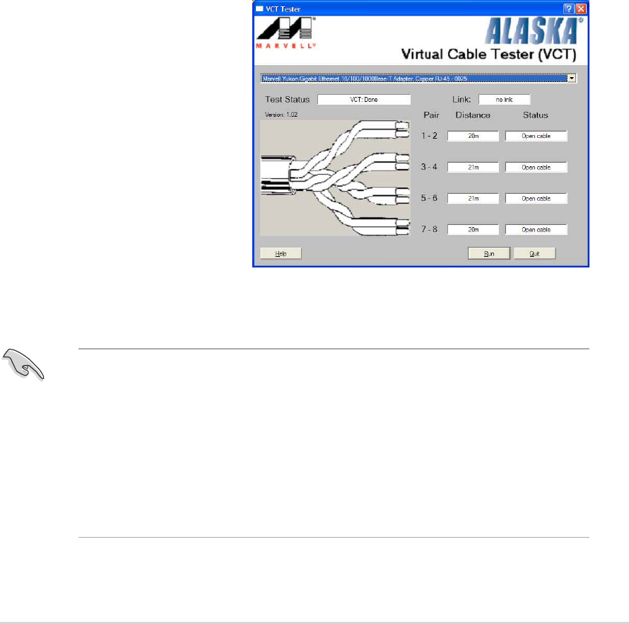
ASUS A8V-E DeluxeASUS A8V-E Deluxe
ASUS A8V-E DeluxeASUS A8V-E Deluxe
ASUS A8V-E Deluxe 5-115-11
5-115-11
5-11
3. Click the RunRun
RunRun
Run button to perform a cable test.
5.3.25.3.2
5.3.25.3.2
5.3.2 AI NET 2AI NET 2
AI NET 2AI NET 2
AI NET 2
The Marvell
®
Virtual Cable Tester™ (VCT) is a cable diagnostic utility that
reports LAN cable faults and shorts using the Time Domain Reflectometry
(TDR) technology. The VCT detects and reports open and shorted cables,
impedance mismatches, pair swaps, pair polarity problems, and pair skew
problems of up to 100 meters at one meter accuracy.
The VCT feature reduces networking and support costs through a highly
manageable and controlled network system. This utility can be incorporated
in the network systems sofware for ideal field support as well as
development diagnostics.
Using the Virtual Cable Tester™Using the Virtual Cable Tester™
Using the Virtual Cable Tester™Using the Virtual Cable Tester™
Using the Virtual Cable Tester™
To use the the Marvell
®
Virtual Cable Tester™ utility:
1. Launch the VCT utility from the Windows
®
desktop by clicking
Start > All Programs > Marvell > Virtual Cable TesterStart > All Programs > Marvell > Virtual Cable Tester
Start > All Programs > Marvell > Virtual Cable TesterStart > All Programs > Marvell > Virtual Cable Tester
Start > All Programs > Marvell > Virtual Cable Tester.
2. Click Virtual CableVirtual Cable
Virtual CableVirtual Cable
Virtual Cable
Tester Tester
Tester Tester
Tester from the menu
to display the screen
below.
•The VCT only runs on systems with Windows
®
XP or Windows
®
2000
operating systems.
• The RunRun
RunRun
Run button on the Virtual Cable Tester™ main window is
disabled if no problem is detected on the LAN cable(s) connected to
the LAN port(s).
•If you want the system to check the LAN cable before entering the
OS, enable the POST Check LAN cablePOST Check LAN cable
POST Check LAN cablePOST Check LAN cable
POST Check LAN cable item in the BIOS. See
section “4.4.7 LAN Cable Status” for details.

5-125-12
5-125-12
5-12 Chapter 5: Software supportChapter 5: Software support
Chapter 5: Software supportChapter 5: Software support
Chapter 5: Software support
5.3.35.3.3
5.3.35.3.3
5.3.3 Audio configurationsAudio configurations
Audio configurationsAudio configurations
Audio configurations
The Realtek
®
ALC850 AC ‘97 audio CODEC provides 8-channel audio
capability to deliver the ultimate audio experience on your PC. The software
provides Jack-Sensing function (Line-In, Line-Out, Mic-In), S/PDIF out
support and interrupt capability. The ALC850 also includes the Realtek
®
proprietary UAJ
®
(Universal Audio Jack) technology for three ports (Line-In,
Line-Out and Mic-In), eliminating cable connection errors and giving users
plug and play convenience.
Follow the installation wizard to install the Realtek ALC850 AudioRealtek ALC850 Audio
Realtek ALC850 AudioRealtek ALC850 Audio
Realtek ALC850 Audio
Driver and ApplicationDriver and Application
Driver and ApplicationDriver and Application
Driver and Application from the support CD that came with the
motherboard package.
If the Realtek audio software is correctly installed, you will find the
SoundEffect icon on the taskbar.
From the taskbar, double-click on the
SoundEffect SoundEffect
SoundEffect SoundEffect
SoundEffect icon to display the RealtekRealtek
RealtekRealtek
Realtek
Audio Control PanelAudio Control Panel
Audio Control PanelAudio Control Panel
Audio Control Panel.
Sound Effect optionsSound Effect options
Sound Effect optionsSound Effect options
Sound Effect options
The Realtek
®
ALC850 Audio CODEC allows you to set your listening
environment, adjust the equalizer, set the karaoke, or select
pre-programmed equalizer settings for your listening pleasure.
The Jack-sensing and UAJ
®
technology features are supported on the
Line-In, Line-Out, and Mic jacks only.
Realtek SoundEffect iconRealtek SoundEffect icon
Realtek SoundEffect iconRealtek SoundEffect icon
Realtek SoundEffect icon

ASUS A8V-E DeluxeASUS A8V-E Deluxe
ASUS A8V-E DeluxeASUS A8V-E Deluxe
ASUS A8V-E Deluxe 5-135-13
5-135-13
5-13
S/PDIF optionS/PDIF option
S/PDIF optionS/PDIF option
S/PDIF option
The Sony/Philips Digital Interface (S/PDIF) options allows you to change
your S/PDIF output settings.
To set the S/PDIF options:
1. From the Realtek Audio Control Panel, click the SPDIF SPDIF
SPDIF SPDIF
SPDIF button.
2. Click the option buttons to change your S/PDIF out settings.
3. Click the Exit (XX
XX
X) button on the upper-right hand corner of the window
to exit.
To set the sound effect options:
1. From the Realtek Audio Control Panel, click the Sound EffectSound Effect
Sound EffectSound Effect
Sound Effect
button.
2. Click the shortcut buttons to change the acoustic environment, adjust
the equalizer, or set the karaoke to your desired settings.
3. The audio settings take effect immediately after you click on the
buttons.
4. Click the Exit (XX
XX
X) button on the upper-right hand corner of the window
to exit.
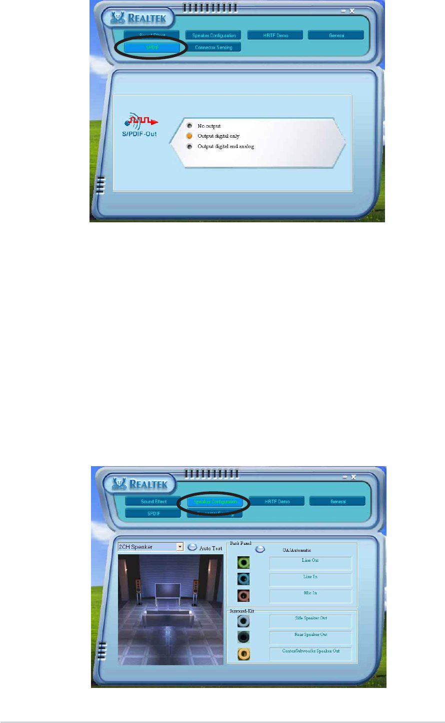
5-145-14
5-145-14
5-14 Chapter 5: Software supportChapter 5: Software support
Chapter 5: Software supportChapter 5: Software support
Chapter 5: Software support
Speaker ConfigurationSpeaker Configuration
Speaker ConfigurationSpeaker Configuration
Speaker Configuration
This option allows you to set your speaker configuration.
To set the speaker configuration:
1. From the Realtek Audio Control Panel, click the SpeakerSpeaker
SpeakerSpeaker
Speaker
Configuration Configuration
Configuration Configuration
Configuration button.
2. Select from the combo list box your current speaker setup, then click
Auto TestAuto Test
Auto TestAuto Test
Auto Test to test your settings.
3. Click the UAJ AutomaticUAJ Automatic
UAJ AutomaticUAJ Automatic
UAJ Automatic button to enable or disable the Universal
Audio Jack(UAJ
®
) technology feature.
4. Click the Exit (XX
XX
X) button on the upper-right hand corner of the window
to exit.
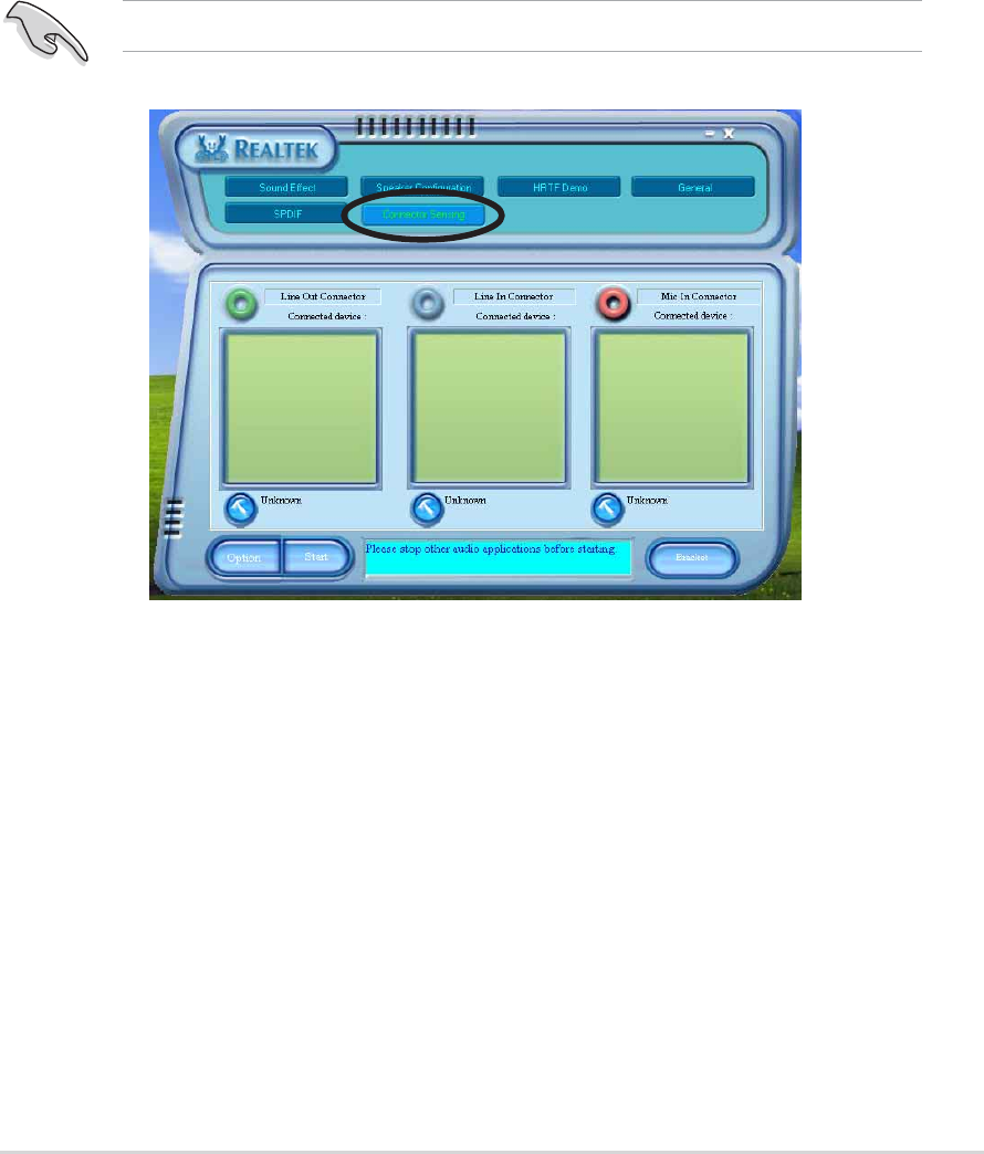
ASUS A8V-E DeluxeASUS A8V-E Deluxe
ASUS A8V-E DeluxeASUS A8V-E Deluxe
ASUS A8V-E Deluxe 5-155-15
5-155-15
5-15
5. When finished, the utility prompts the Realtek
®
EZ-connection dialog
box showing your current audio connections. The text at the bottom
of the box explains your audio connection status. An
X mark
denotes
an incorrect connection.
AI Audio featureAI Audio feature
AI Audio featureAI Audio feature
AI Audio feature
The AI Audio feature works through the connector sensing option that
allows you to check if your audio devices are connected properly.
To start the connector sensing:
1. From the Realtek Audio Control Panel, click the Connector SensingConnector Sensing
Connector SensingConnector Sensing
Connector Sensing
button.
2. Click the Bracket Bracket
Bracket Bracket
Bracket button to display connected audio devices.
3. Click the Option Option
Option Option
Option button to change sensing options.
4. Click the Start Start
Start Start
Start button to start connection sensing. A progress bar
displays current connector sensing status.
Make sure to exit all audio applications before starting this function.
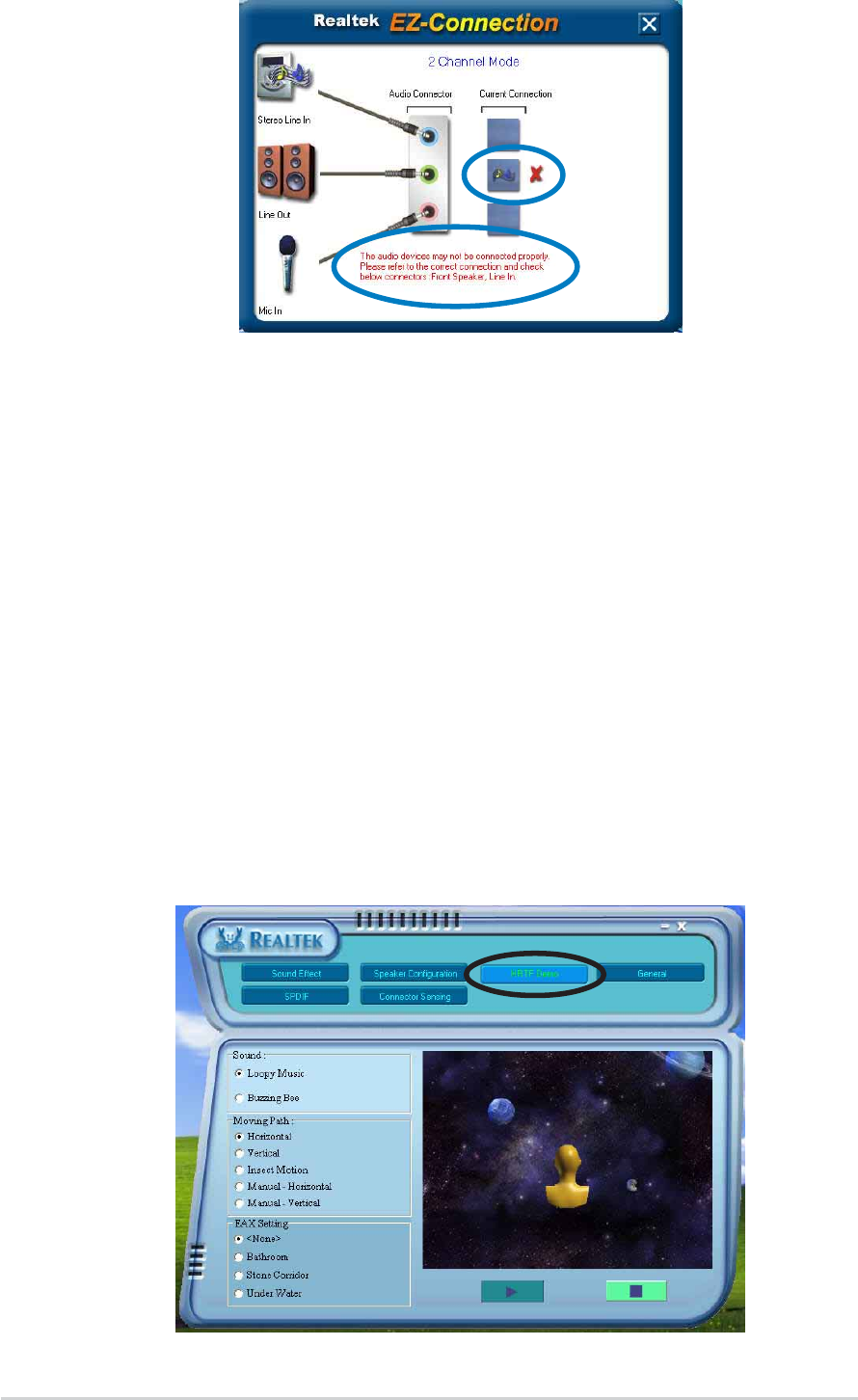
5-165-16
5-165-16
5-16 Chapter 5: Software supportChapter 5: Software support
Chapter 5: Software supportChapter 5: Software support
Chapter 5: Software support
6. If there are detected problems, make sure that your audio cables are
connected to the proper audio jack and repeat connector sensing.
7. Click the X X
X X
X button to exit EZ-connection dialog box.
8. Click the Exit (XX
XX
X) button on the upper-right hand corner of the window
to exit audio control panel.
HRTF DemoHRTF Demo
HRTF DemoHRTF Demo
HRTF Demo
This option shows a demo of the Head-Related Transfer Functions (HRTF).
To start the HRTF demo:
1. From the Realtek Audio Control Panel, click the HRTF Demo HRTF Demo
HRTF Demo HRTF Demo
HRTF Demo button.
2. Click the option buttons to change the sound, moving path or EAX
settings.
3. Click the Play Play
Play Play
Play button to start or the Stop Stop
Stop Stop
Stop button to stop.
4. Click the Exit (XX
XX
X) button on the upper-right hand corner of the window
to exit.
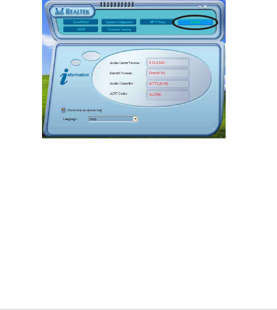
ASUS A8V-E DeluxeASUS A8V-E Deluxe
ASUS A8V-E DeluxeASUS A8V-E Deluxe
ASUS A8V-E Deluxe 5-175-17
5-175-17
5-17
Rear panel audio ports function variationRear panel audio ports function variation
Rear panel audio ports function variationRear panel audio ports function variation
Rear panel audio ports function variation
The functions of the Line Out (lime), Line In (blue), Mic (pink), Rear
Speaker Out (gray), Side Speaker Out (black), and Center/Subwoofer
(yellow orange) ports on the rear panel change when you select the
4-channel, 6-channel or 8-channel audio configurations. See the 8, 6, 4 or
2-channel speaker configuration on page 2-23.
General settingsGeneral settings
General settingsGeneral settings
General settings
This option shows the audio settings and allows you to change the
language setting or toggle the SoundEffect icon display on the Windows
taskbar.
To display the general settings:
1. From the Realtek Audio Control Panel, click the General General
General General
General button.
2. Click the option button to enable or disable the icon display on the
Windows taskbar.
3. Click the Language Language
Language Language
Language combo list box to change language display.
4. Click the Exit (XX
XX
X) button on the upper-right hand corner of the window
to exit.

5-185-18
5-185-18
5-18 Chapter 5: Software supportChapter 5: Software support
Chapter 5: Software supportChapter 5: Software support
Chapter 5: Software support
5.4 RAID configurations
The motherboard comes with the VIA VT8237R Southbridge RAID
controller that allows you to configure Serial ATA hard disk drives as RAID
sets. The motherboard supports the following RAID configurations.
RAID 0RAID 0
RAID 0RAID 0
RAID 0
(Data striping)
optimizes two identical hard disk drives to read and
write data in parallel, interleaved stacks. Two hard disks perform the same
work as a single drive but at a sustained data transfer rate, double that of
a single disk alone, thus improving data access and storage. Use of two
new identical hard disk drives is required for this setup.
RAID 1RAID 1
RAID 1RAID 1
RAID 1
(Data mirroring)
copies and maintains an identical image of data
from one drive to a second drive. If one drive fails, the disk array
management software directs all applications to the surviving drive as it
contains a complete copy of the data in the other drive. This RAID
configuration provides data protection and increases fault tolerance to the
entire system. Use two new drives or use an existing drive and a new drive
for this setup. The new drive must be of the same size or larger than the
existing drive.
If you want to boot the system from a hard disk drive included in a RAID
set, copy first the RAID driver from the support CD to a floppy disk
before you install an operating system to a selected hard disk drive.
Refer to section “5.5 Creating a RAID driver disk” for details.
5.4.15.4.1
5.4.15.4.1
5.4.1 Installing hard disksInstalling hard disks
Installing hard disksInstalling hard disks
Installing hard disks
The motherboard supports Serial ATA hard disk drives. For optimal
performance, install identical drives of the same model and capacity when
creating a disk array.
Installing Serial ATA (SATA) hard disksInstalling Serial ATA (SATA) hard disks
Installing Serial ATA (SATA) hard disksInstalling Serial ATA (SATA) hard disks
Installing Serial ATA (SATA) hard disks
To install the SATA hard disks for a RAID configuration:
1. Install the SATA hard disks into the drive bays.
2. Connect the SATA signal cables.
3. Connect a SATA power cable to the power connector on each drive.

ASUS A8V-E DeluxeASUS A8V-E Deluxe
ASUS A8V-E DeluxeASUS A8V-E Deluxe
ASUS A8V-E Deluxe 5-195-19
5-195-19
5-19
Entering VIA Tech RAID BIOS UtilityEntering VIA Tech RAID BIOS Utility
Entering VIA Tech RAID BIOS UtilityEntering VIA Tech RAID BIOS Utility
Entering VIA Tech RAID BIOS Utility
1. Boot-up your computer.
2. During POST, press <Tab> to enter VIA RAID configuration utility.
The following menu options will appear.
On the upper-right side of the screen is the message and legend box. The
keys on the legend box allows you to navigate through the setup menu
options. The message describes the function of each menu item. The
following lists the keys found in the legend box with their corresponding
functions.
<F1><F1>
<F1><F1>
<F1> : View Array/Disk Status
↑, ,
, ,
, ↓:Move to the next item
<Enter><Enter>
<Enter><Enter>
<Enter> : Confirm the selection
<ESC><ESC>
<ESC><ESC>
<ESC> : Exit
The RAID BIOS information on the setup screen shown below is for
reference only. What you see on your screen may not exactly match
what is shown here.
5.4.25.4.2
5.4.25.4.2
5.4.2 VIA RAID configurationsVIA RAID configurations
VIA RAID configurationsVIA RAID configurations
VIA RAID configurations
The motherboard includes a high performance IDE RAID controller
integrated in the VIA VT8237R southbridge chipset. It supports RAID 0 and
RAID 1 with two independent Serial ATA channels.
Create Array
Delete Array
Create/Delete Spare
Select Boot Array
Serial Number View
VIA Tech. RAID BIOS Ver 1.xx
Create a RAID array with
the hard disks attached to
VIA RAID controller
F1 : View Array/Disk Status
↑
,
↓
: Move to next item
Enter : Confirm the selection
ESC : Exit
Channel Drive Name Array Name Mode Size(GB) Status
Serial_Ch0 Master XXXXXXXXXXX ARRAY 0 SATA 999.99 XXXXXXX
Serial_Ch1 Master XXXXXXXXXXX ARRAY 0 SATA 999.99 XXXXXXX

5-205-20
5-205-20
5-20 Chapter 5: Software supportChapter 5: Software support
Chapter 5: Software supportChapter 5: Software support
Chapter 5: Software support
Create ArrayCreate Array
Create ArrayCreate Array
Create Array
1. From the VIA RAID BIOS utility main menu, select Create ArrayCreate Array
Create ArrayCreate Array
Create Array then
press <Enter><Enter>
<Enter><Enter>
<Enter>. The main menu items on the upper-left corner of the
screen are replaced with create array menu options.
RAID 0 for performanceRAID 0 for performance
RAID 0 for performanceRAID 0 for performance
RAID 0 for performance
1. From the create array menu, select Array ModeArray Mode
Array ModeArray Mode
Array Mode, then press
<Enter>. The supported RAID configurations appear on a pop-up
menu.
2. Select RAID 0 for performanceRAID 0 for performance
RAID 0 for performanceRAID 0 for performance
RAID 0 for performance then press <Enter>.
From this point, you may choose to auto-configure the RAID array by
selecting Auto Setup for PerformanceAuto Setup for Performance
Auto Setup for PerformanceAuto Setup for Performance
Auto Setup for Performance or manually configure the
RAID array for stripped sets. If you want to auto-configure, proceed
to the next step, otherwise, skip to step 5.
3. Select Auto Setup for PerformanceAuto Setup for Performance
Auto Setup for PerformanceAuto Setup for Performance
Auto Setup for Performance and press <Enter>. The
following confirmation message appears.
RAID 1 for data protection
RAID 0/1
RAID SPAN for capacity
RAID 0 for performance
Auto create array will destroy all
data on disks, Continue? (Y/N)
Auto Setup For Data Security
Array Mode RAID 1 (Mirroring)
Select Disk Drives
Start Create Process
VIA Tech. RAID BIOS Ver 1.xx
Create a RAID array with
the hard disks attached to
VIA RAID controller
F1 : View Array/Disk Status
↑
,
↓
: Move to next item
Enter : Confirm the selection
ESC : Exit
Channel Drive Name Array Name Mode Size(GB) Status
Serial_Ch0 Master XXXXXXXXXXX ARRAY 0 SATA 999.99 XXXXXXX
Serial_Ch1 Master XXXXXXXXXXX ARRAY 0 SATA 999.99 XXXXXXX

ASUS A8V-E DeluxeASUS A8V-E Deluxe
ASUS A8V-E DeluxeASUS A8V-E Deluxe
ASUS A8V-E Deluxe 5-215-21
5-215-21
5-21
Use arrow keys to move selection bar on items and press <Enter> to
select.
7. Select Start Create ProcessStart Create Process
Start Create ProcessStart Create Process
Start Create Process and press <Enter> to set up hard disk
for RAID system. The following confirmation message appears:
8. Press <Y> to confirm or <N> to return to the configuration options.
9. Press <Esc> to go back to main menu.
RAID 1 for data protectionRAID 1 for data protection
RAID 1 for data protectionRAID 1 for data protection
RAID 1 for data protection
1. From the create array menu, select Array ModeArray Mode
Array ModeArray Mode
Array Mode, then press <Enter>.
The supported RAID configurations appear on a pop-up menu.
The data on the selected disks will
be destroyed. Continue? (Y/N)
4K
8K
16K
32K
64K
RAID 0 for performance
RAID 1 for data protection
RAID 0/1
RAID SPAN for capacity
RAID 1 for data protection
TIP: TIP:
TIP: TIP:
TIP: For server systems, use of a lower array
block size is recommended. For multimedia
computer systems used mainly for audio and
video editing, a higher array block size is
recommended for optimum performance.
4. Press <Y> to confirm or <N> to return to the configuration options. If
you selected <Y>, proceed to step 9.
5. Select Select Disk DrivesSelect Disk Drives
Select Disk DrivesSelect Disk Drives
Select Disk Drives, then press <Enter>. Use arrow keys to
select disk drive, then press <Enter> to mark selected drive. An
asterisk appears before a selected drive.
6. Select Block SizeBlock Size
Block SizeBlock Size
Block Size, then press <Enter> to set array block size. A list
of valid array block sizes are displayed on a pop-up menu.
2. Select RAID 1 for data protectionRAID 1 for data protection
RAID 1 for data protectionRAID 1 for data protection
RAID 1 for data protection then press <Enter>.

5-225-22
5-225-22
5-22 Chapter 5: Software supportChapter 5: Software support
Chapter 5: Software supportChapter 5: Software support
Chapter 5: Software support
8. If you select <Y> the utility will duplicate your data. Press <Y>
anytime if you want to exit the duplication process.
3. From this point, you can auto-configure the RAID array by selecting
Auto Setup for Data SecurityAuto Setup for Data Security
Auto Setup for Data SecurityAuto Setup for Data Security
Auto Setup for Data Security or manually configure the RAID
array for mirrored sets. If you want to auto-configure, proceed to the
next step, otherwise, skip to step 6.
4. Select Auto Setup for Data SecurityAuto Setup for Data Security
Auto Setup for Data SecurityAuto Setup for Data Security
Auto Setup for Data Security and press <Enter>. The
following confirmation message appears.
The data on the selected disks will
be destroyed. Continue? (Y/N)
10. Press <Y> to confirm or <N> to return to the configuration options.
11. Press <Esc> to go back to main menu.
Auto create array will destroy all
data on disks, Continue? (Y/N)
5. Press <Y> to confirm or <N> to return to the configuration options. If
you selected <Y>, proceed to step 11.
6. Select Select Disk DrivesSelect Disk Drives
Select Disk DrivesSelect Disk Drives
Select Disk Drives, then press <Enter>. Use arrow keys to
select disk drive/s, then press <Enter>. An asterisk appears before a
selected drive.
7. Select Start Create ProcessStart Create Process
Start Create ProcessStart Create Process
Start Create Process and press <Enter> to setup hard disk
for RAID system. The following inquiry appears:
Save the data on source disk to
mirror after creation? (Y/N)
Duplicating...
RAID 1 for data protection
Press Yes(Y) to Escape
9. If you select <N>, the following confirmation message appears.

ASUS A8V-E DeluxeASUS A8V-E Deluxe
ASUS A8V-E DeluxeASUS A8V-E Deluxe
ASUS A8V-E Deluxe 5-235-23
5-235-23
5-23
RAID Span for capacityRAID Span for capacity
RAID Span for capacityRAID Span for capacity
RAID Span for capacity
1. From the create array menu, select Array ModeArray Mode
Array ModeArray Mode
Array Mode, then press <Enter>.
The supported RAID configurations appear on a pop-up menu.
2. Select RAID SPAN for capacityRAID SPAN for capacity
RAID SPAN for capacityRAID SPAN for capacity
RAID SPAN for capacity then press <Enter>.
3. From this point, you can auto-configure the RAID array by selecting
Auto Setup for Capacity Auto Setup for Capacity
Auto Setup for Capacity Auto Setup for Capacity
Auto Setup for Capacity or manually configure the RAID array for
spanned sets. If you want to auto-configure, continue with next step;
otherwise, proceed to step 6.
4. Select Auto Setup for CapacityAuto Setup for Capacity
Auto Setup for CapacityAuto Setup for Capacity
Auto Setup for Capacity and press <Enter>. The following
confirmation message appears.
RAID 0 for performance
RAID 1 for data protection
RAID 0/1
RAID SPAN for capacity
RAID SPAN for capacity
Auto create array will destroy all
data on disks, Continue? (Y/N)
5. Press <Y> to confirm or <N> to return to the configuration options. If
you selected <Y>, proceed to step 11.
6. Select Select Disk DrivesSelect Disk Drives
Select Disk DrivesSelect Disk Drives
Select Disk Drives, then press <Enter>. Use arrow keys to
select disk drive/s, then press <Enter>. An asterisk appears before a
selected drive.
7. Select Start Create ProcessStart Create Process
Start Create ProcessStart Create Process
Start Create Process and press <Enter> to start RAID
system setup. The following inquiry appears:
8. If you select <Y>, the utility will save your disk data on Span 0 disk
then configure the RAID set. Proceed to step 11.
9. If you select <N>, the following confirmation message appears.
The data on the selected disks will
be destroyed. Continue? (Y/N)
Save the data on Span 0 disk
after creation? (Y/N)

5-245-24
5-245-24
5-24 Chapter 5: Software supportChapter 5: Software support
Chapter 5: Software supportChapter 5: Software support
Chapter 5: Software support
Delete ArrayDelete Array
Delete ArrayDelete Array
Delete Array
1. From the VIA RAID BIOS utility main menu, select Delete ArrayDelete Array
Delete ArrayDelete Array
Delete Array then
press <Enter>.
3. Press <Y> to confirm or <N> to return to the configuration options.
The selected array will be destroyed.
Are you sure? Continue? Press Y/N
10. Press <Y> to confirm or <N> to return to the configuration options.
11. Press <Esc> to go back to main menu.
Select Boot ArraySelect Boot Array
Select Boot ArraySelect Boot Array
Select Boot Array
1. From the VIA RAID BIOS utility main menu, select Select BootSelect Boot
Select BootSelect Boot
Select Boot
ArrayArray
ArrayArray
Array then press <Enter>.
2. From the list of channel used for IDE RAID arrays, press <Enter> to
select a RAID array for boot. After selection, the StatusStatus
StatusStatus
Status of the
selected array will change to Boot.
3. Press <ESC> to return to the menu items. Follow the same procedure
to deselect the the boot array.
2. From the list of channel used for IDE RAID arrays, press <Enter><Enter>
<Enter><Enter>
<Enter> to
select a RAID array to delete. The following confirmation message
appears.
Create Array
Delete Array
Create/Delete Spare
Select Boot Array
Serial Number View
VIA Tech. RAID BIOS Ver 1.xx
Create a RAID array with
the hard disks attached to
VIA RAID controller
F1 : View Array/Disk Status
↑
,
↓
: Move to next item
Enter : Confirm the selection
ESC : Exit
Channel Drive Name Array Name Mode Size(GB) Status
[ ]Serial_Ch0 Master XXXXXXXXXXX ARRAY 0 SATA 999.99 XXXXXXX
[ ]Serial_Ch1 Master XXXXXXXXXXX ARRAY 0 SATA 999.99 XXXXXXX
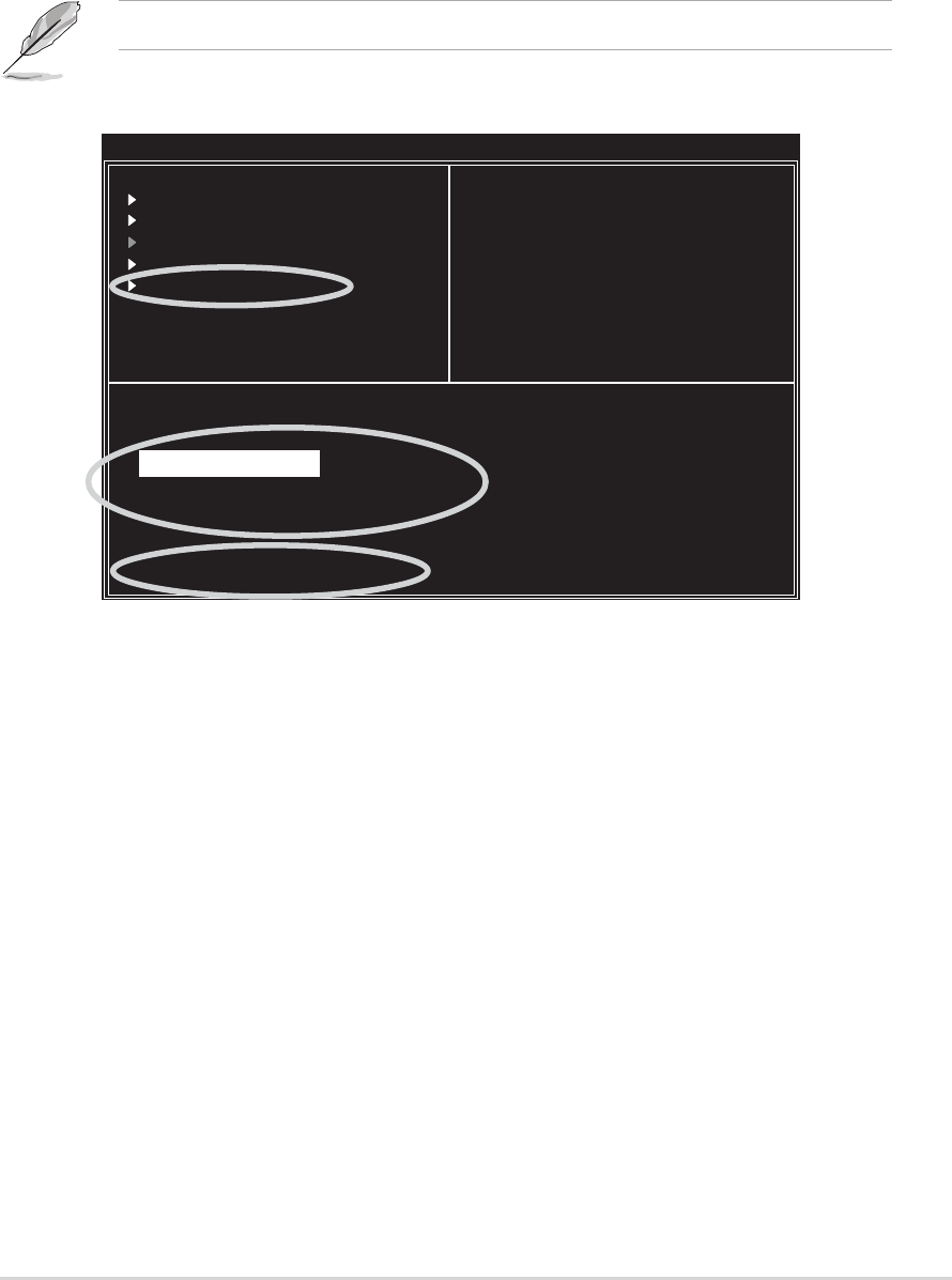
ASUS A8V-E DeluxeASUS A8V-E Deluxe
ASUS A8V-E DeluxeASUS A8V-E Deluxe
ASUS A8V-E Deluxe 5-255-25
5-255-25
5-25
Serial Number ViewSerial Number View
Serial Number ViewSerial Number View
Serial Number View
1. From the VIA RAID BIOS utility main menu, select Serial NumberSerial Number
Serial NumberSerial Number
Serial Number
ViewView
ViewView
View then press <Enter>.
2. From the list of channel used for IDE RAID arrays, use the arrow keys
to move the selection bar on each item. The serial number for the
selected drive is displayed at the bottom of the screen.
Create Array
Delete Array
Create/Delete Spare
Select Boot Array
Serial Number View
VIA Tech. RAID BIOS Ver 1.xx
Create a RAID array with
the hard disks attached to
VIA RAID controller
F1 : View Array/Disk Status
↑
,
↓
: Move to next item
Enter : Confirm the selection
ESC : Exit
Channel Drive Name Array Name Mode Size(GB) Status
Serial_Ch0 Master XXXXXXXXXXX ARRAY 0 SATA 999.99 XXXXXXX
Serial_Ch1 Master XXXXXXXXXXX ARRAY 0 SATA 999.99 XXXXXXX
Serial Number: XXXXXXXX
Serial_Ch0 Master
This option is useful for identifying same model disks.

5-265-26
5-265-26
5-26 Chapter 5: Software supportChapter 5: Software support
Chapter 5: Software supportChapter 5: Software support
Chapter 5: Software support
5.5 Creating a RAID driver disk
A floppy disk with the RAID driver is required when installing Windows
®
2000/XP operating system on a hard disk drive that is included in a RAID
set.
To create a RAID driver disk:
1. Place the motherboard support CD into the CD-ROM drive.
2. When the Drivers Drivers
Drivers Drivers
Drivers menu appears, click Make VIA 6420 RAIDMake VIA 6420 RAID
Make VIA 6420 RAIDMake VIA 6420 RAID
Make VIA 6420 RAID
Driver DiskDriver Disk
Driver DiskDriver Disk
Driver Disk to create a VIA RAID driver disk
Or
Browse the contents of the support CD to locate the driver disk utility
and go to \Drivers\VIARAID\6420RAID\Drivers\VIARAID\6420RAID
\Drivers\VIARAID\6420RAID\Drivers\VIARAID\6420RAID
\Drivers\VIARAID\6420RAID for the VIA RAID
driver disk utility
3Insert floppy disk to floppy disk drive.
5. Follow succeeding screen information to complete process.
6. Write-protect the floppy disk to avoid computer virus infection.
To install the RAID driver:
1. During the OS installation, the system prompts you to press the F6
key to install third-party SCSI or RAID driver.
2. Press <F6>
then insert the floppy disk with RAID driver into the floppy
disk drive.
3. Follow the succeeding screen instructions to complete the installation.
Refer to section “5.2.2 Drivers menu” for details.
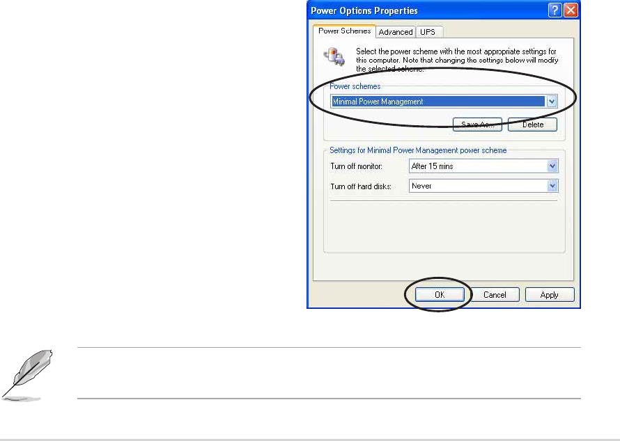
ASUS A8V-E DeluxeASUS A8V-E Deluxe
ASUS A8V-E DeluxeASUS A8V-E Deluxe
ASUS A8V-E Deluxe 5-275-27
5-275-27
5-27
5.6 Cool ‘n’ Quiet!™ Technology
The motherboard supports the AMD Cool ‘n’ Quiet!™ Technology that
dynamically and automatically change the CPU speed, voltage, and amount
of power depending on the task the CPU performs.
5.6.15.6.1
5.6.15.6.1
5.6.1 Enabling Cool ‘n’ Quiet!™ TechnologyEnabling Cool ‘n’ Quiet!™ Technology
Enabling Cool ‘n’ Quiet!™ TechnologyEnabling Cool ‘n’ Quiet!™ Technology
Enabling Cool ‘n’ Quiet!™ Technology
To enable Cool ‘n’ Quiet!™ Technology:
1. Turn on the system and enter BIOS by pressing the <Del>
key during
the Power On Self-Tests (POST).
2. In the Advanced > CPU Configuration > AMD CPU Cool &Advanced > CPU Configuration > AMD CPU Cool &
Advanced > CPU Configuration > AMD CPU Cool &Advanced > CPU Configuration > AMD CPU Cool &
Advanced > CPU Configuration > AMD CPU Cool &
Quiet ConfigurationQuiet Configuration
Quiet ConfigurationQuiet Configuration
Quiet Configuration menu, select the item Cool N’QuietCool N’Quiet
Cool N’QuietCool N’Quiet
Cool N’Quiet and set
it to EnabledEnabled
EnabledEnabled
Enabled. See section “4.4 Advanced Menu” in the user guide.
3. In the Power Power
Power Power
Power menu, select the item ACPI 2.0 SupportACPI 2.0 Support
ACPI 2.0 SupportACPI 2.0 Support
ACPI 2.0 Support and set it
to YesYes
YesYes
Yes. See section “4.5 Power Menu” in the user guide.
4. Save your changes and exit BIOS Setup.
5. Reboot your computer and set your Power Option Properties
depending on your operating system.
WindowsWindows
WindowsWindows
Windows
®®
®®
®
2000/XP 2000/XP
2000/XP 2000/XP
2000/XP
1. From the Windows
®
2000/XP operating system, click the StartStart
StartStart
Start
button. Select SettingsSettings
SettingsSettings
Settings, then Control PanelControl Panel
Control PanelControl Panel
Control Panel.
2. Make sure the Control Panel is set to Classic View.
3. Double-click the Display Display
Display Display
Display icon in
the Control Panel then select the
Screen SaverScreen Saver
Screen SaverScreen Saver
Screen Saver tab.
4. Click the Power...Power...
Power...Power...
Power... button. The
following dialog box appears.
5. From the Power schemesPower schemes
Power schemesPower schemes
Power schemes
combo list box, select MinimalMinimal
MinimalMinimal
Minimal
Power ManagementPower Management
Power ManagementPower Management
Power Management.
6. Click OK OK
OK OK
OK to effect settings.
Make sure to install the Cool ‘n’ Quiet!™ driver and application before
using this feature.

5-285-28
5-285-28
5-28 Chapter 5: Software supportChapter 5: Software support
Chapter 5: Software supportChapter 5: Software support
Chapter 5: Software support
5.6.25.6.2
5.6.25.6.2
5.6.2 Launching the Cool ‘n’ Quiet!™ softwareLaunching the Cool ‘n’ Quiet!™ software
Launching the Cool ‘n’ Quiet!™ softwareLaunching the Cool ‘n’ Quiet!™ software
Launching the Cool ‘n’ Quiet!™ software
The motherboard support CD includes the Cool ‘n’ Quiet!™ software that
enables you to view your system’s real-time CPU Frequency and voltage.
To launch the Cool ‘n’ Quiet!™ program:
1. If you are using Windows
®
2000, click the StartStart
StartStart
Start button. Select
Programs > ASUS > Cool & Quiet > Cool & Quiet.Programs > ASUS > Cool & Quiet > Cool & Quiet.
Programs > ASUS > Cool & Quiet > Cool & Quiet.Programs > ASUS > Cool & Quiet > Cool & Quiet.
Programs > ASUS > Cool & Quiet > Cool & Quiet.
2. If you are using Windows
®
XP, click the StartStart
StartStart
Start button. Select AllAll
AllAll
All
Programs > ASUS > Cool & Quiet > Cool & Quiet.Programs > ASUS > Cool & Quiet > Cool & Quiet.
Programs > ASUS > Cool & Quiet > Cool & Quiet.Programs > ASUS > Cool & Quiet > Cool & Quiet.
Programs > ASUS > Cool & Quiet > Cool & Quiet.
3. The Cool ‘n’ Quiet!™ technology screen appears and displays the
current CPU Frequency and CPU Voltage.
Make sure to install the Cool ‘n’ Quiet!™ software from the motherboard
support CD. Refer to section “5.2.3 Utilities menu”, for details.