ASUSTeK Computer MWOM4LA MOTHERBOARD User Manual FRONT A8V E Deluxe P65
ASUSTeK Computer Inc MOTHERBOARD FRONT A8V E Deluxe P65
UserManual.wiki
>
ASUSTeK Computer
>
MWOM4LA User Manual
>
USERS MANUAL 2
Contents
1.
users manual
2.
USERS MANUAL 1
3.
USERS MANUAL 2
USERS MANUAL 2
Navigation menu
Upload a User Manual
Namespaces
Wiki Guide
HTML
PDF
Info
Views
User Manual
Discussion / Help
Navigation
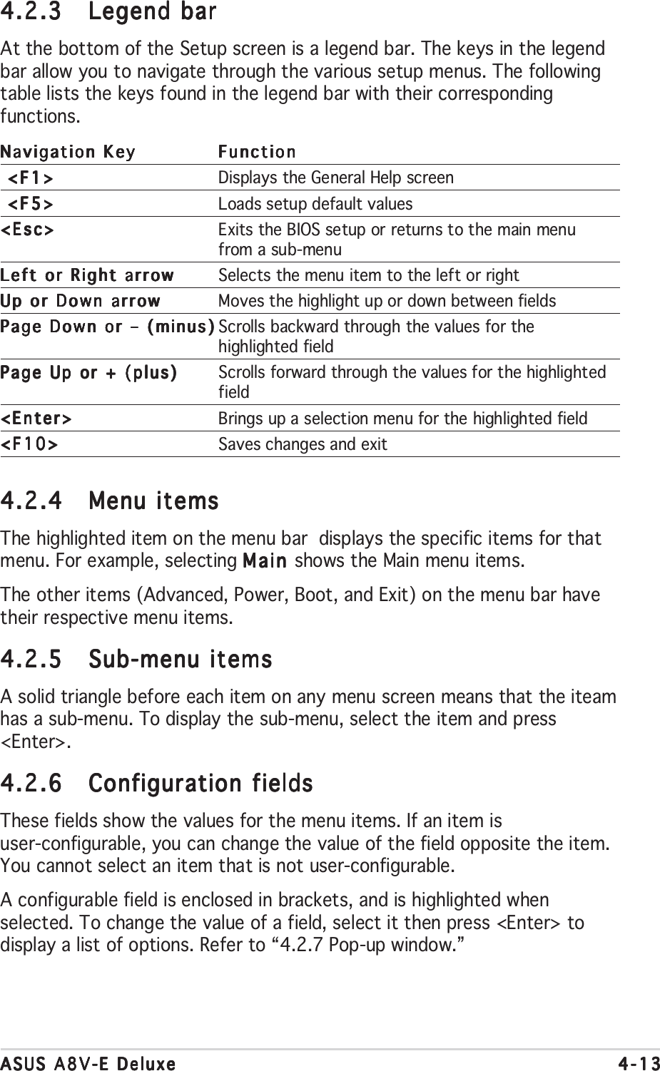
![4-124-124-124-124-12 Chapter 4: BIOS setupChapter 4: BIOS setupChapter 4: BIOS setupChapter 4: BIOS setupChapter 4: BIOS setupF1:Help ↑↓ : Select Item -/+: Change Value F5: Setup DefaultsESC: Exit →←: Select Menu Enter: Select Sub-menu F10: Save and ExitPhoenix-Award BIOS CMOS Setup Utility Main Advanced Power Boot ExitSelect MenuItem Specific HelpChange the day, month,year and century.System Time 15 : 30 : 36System Date Wed, Sep 15 2004Language [English]Legacy Diskette A: [1.44M, 3.5 in.]Primary IDE Master [ST321122A]Primary IDE Slave [ASUS CDS520/A]Secondary IDE Master [None]Secondary IDE Slave [None]HDD SMART Monitoring [Disabled]Installed Memory 256MB4.2.24.2.24.2.24.2.24.2.2 Menu barMenu barMenu barMenu barMenu barThe menu bar on top of the screen has the following main items:MainMainMainMainMain For changing the basic system configurationAdvancedAdvancedAdvancedAdvancedAdvanced For changing the advanced system settingsPowerPowerPowerPowerPower For changing the advanced power management (APM)configurationBootBootBootBootBoot For changing the system boot configurationExitExitExitExitExit For selecting the exit options and loading default settingsTo select an item on the menu bar, press the right or left arrow key on thekeyboard until the desired item is highlighted.4.2.14.2.14.2.14.2.14.2.1 BIOS menu screenBIOS menu screenBIOS menu screenBIOS menu screenBIOS menu screen•The BIOS setup screens shown in this chapter are for referencepurposes only, and may not exactly match what you see on yourscreen.•Visit the ASUS website (www.asus.com) to download the latest BIOSinformation.Legend barLegend barLegend barLegend barLegend barGeneral helpGeneral helpGeneral helpGeneral helpGeneral helpMenu barMenu barMenu barMenu barMenu barSub-menu itemsSub-menu itemsSub-menu itemsSub-menu itemsSub-menu itemsConfiguration fieldsConfiguration fieldsConfiguration fieldsConfiguration fieldsConfiguration fieldsMenu itemsMenu itemsMenu itemsMenu itemsMenu items](https://usermanual.wiki/ASUSTeK-Computer/MWOM4LA.USERS-MANUAL-2/User-Guide-503729-Page-14.png)
![4-144-144-144-144-14 Chapter 4: BIOS setupChapter 4: BIOS setupChapter 4: BIOS setupChapter 4: BIOS setupChapter 4: BIOS setup4.2.74.2.74.2.74.2.74.2.7 Pop-up windowPop-up windowPop-up windowPop-up windowPop-up windowSelect a menu item then press <Enter> to display a pop-up window withthe configuration options for that item.F1:Help ↑↓ : Select Item -/+: Change Value F5: Setup DefaultsESC: Exit →←: Select Menu Enter: Select Sub-menu F10: Save and ExitPhoenix-Award BIOS CMOS Setup Utility Main Advanced Power Boot ExitSelect MenuItem Specific HelpSpecifies the capacityand physical size ofdiskette drive A.System Time 15 : 30 : 36System Date Wed, Sep 15 2004Legacy Diskette A: [1.44M, 3.5 in.]Primary IDE Master [ST321122A]Primary IDE Slave [ASUS CDS520/A]Secondary IDE Master [None]Secondary IDE Slave [None]HDD SMART Monitoring [Disabled]Installed Memory 256MBLegacy Diskette A:Disabled ..... [ ]360K , 5.25 in. ..... [ ]1.2M , 5.25 in. ..... [ ]720K , 3.5 in. ..... [ ]1.44M, 3.5 in. ..... [ ]2.88M, 3.5 in. ..... [ ] ↑↓ :Move ENTER:Accept ESC:AbortPop-up menuPop-up menuPop-up menuPop-up menuPop-up menu4.2.84.2.84.2.84.2.84.2.8 General helpGeneral helpGeneral helpGeneral helpGeneral helpAt the top right corner of the menu screen is a brief description of theselected item.](https://usermanual.wiki/ASUSTeK-Computer/MWOM4LA.USERS-MANUAL-2/User-Guide-503729-Page-16.png)
![ASUS A8V-E DeluxeASUS A8V-E DeluxeASUS A8V-E DeluxeASUS A8V-E DeluxeASUS A8V-E Deluxe 4-154-154-154-154-15F1:Help ↑↓ : Select Item -/+: Change Value F5: Setup DefaultsESC: Exit →←: Select Menu Enter: Select Sub-menu F10: Save and ExitPhoenix-Award BIOS CMOS Setup Utility Main Advanced Power Boot ExitSelect MenuItem Specific HelpChange the day, month,year and century.System Time 15 : 30 : 36System Date Wed, Sep 15 2004Language [English]Legacy Diskette A: [1.44M, 3.5 in.]Primary IDE Master [ST321122A]Primary IDE Slave [ASUS CDS520/A]Secondary IDE Master [None]Secondary IDE Slave [None]HDD SMART Monitoring [Disabled]Installed Memory 256MB4.3 Main menuWhen you enter the BIOS Setup program, the Main menu screen appears,giving you an overview of the basic system information.Refer to section “4.2.1 BIOS menu screen” for information on the menuscreen items and how to navigate through them.4.3.14.3.14.3.14.3.14.3.1 System Time [xx:xx:xxxx]System Time [xx:xx:xxxx]System Time [xx:xx:xxxx]System Time [xx:xx:xxxx]System Time [xx:xx:xxxx]Allows you to set the system time.4.3.24.3.24.3.24.3.24.3.2 System Date [Day xx/xx/xxxx]System Date [Day xx/xx/xxxx]System Date [Day xx/xx/xxxx]System Date [Day xx/xx/xxxx]System Date [Day xx/xx/xxxx]Allows you to set the system date.4.3.34.3.34.3.34.3.34.3.3 Language [English]Language [English]Language [English]Language [English]Language [English]Allows you to choose the BIOS language version from the options.Configuration options: [English] [French] [German]4.3.44.3.44.3.44.3.44.3.4 Legacy Diskette A [1.44M, 3.5 in.]Legacy Diskette A [1.44M, 3.5 in.]Legacy Diskette A [1.44M, 3.5 in.]Legacy Diskette A [1.44M, 3.5 in.]Legacy Diskette A [1.44M, 3.5 in.]Sets the type of floppy drive installed. Configuration options: [Disabled][360K, 5.25 in.] [1.2M , 5.25 in.] [720K , 3.5 in.] [1.44M, 3.5 in.][2.88M, 3.5 in.]](https://usermanual.wiki/ASUSTeK-Computer/MWOM4LA.USERS-MANUAL-2/User-Guide-503729-Page-17.png)
![4-164-164-164-164-16 Chapter 4: BIOS setupChapter 4: BIOS setupChapter 4: BIOS setupChapter 4: BIOS setupChapter 4: BIOS setupBefore attempting to configure a hard disk drive, make sure you havethe correct configuration information supplied by the drivemanufacturer. Incorrect settings may cause the system to fail torecognize the installed hard disk.4.3.54.3.54.3.54.3.54.3.5 Primary and Secondary IDE Master/SlavePrimary and Secondary IDE Master/SlavePrimary and Secondary IDE Master/SlavePrimary and Secondary IDE Master/SlavePrimary and Secondary IDE Master/SlaveWhile entering Setup, the BIOS automatically detects the presence of IDEdevices. There is a separate sub-menu for each IDE device. Select a deviceitem then press <Enter> to display the IDE device information.The BIOS automatically detects the values opposite the dimmed items(Capacity, Cylinder, Head, Sector and Transfer Mode). These values are notuser-configurable. These items show N/A if no IDE device is installed in thesystem.Primary/Secondary IDE Master/Slave [Auto]Primary/Secondary IDE Master/Slave [Auto]Primary/Secondary IDE Master/Slave [Auto]Primary/Secondary IDE Master/Slave [Auto]Primary/Secondary IDE Master/Slave [Auto]Select [Auto] to automatically detect an IDE hard disk drive. If automaticdetection is successful, the BIOS automatically fills in the correct values forthe remaining fields on this sub-menu. If the hard disk was alreadyformatted on a previous system, the setup BIOS may detect incorrectparameters. Select [Manual] to manually enter the IDE hard disk driveparameters. If no drive is installed select [None].Configuration options: [None] [Auto] [Manual]Access Mode [Auto]Access Mode [Auto]Access Mode [Auto]Access Mode [Auto]Access Mode [Auto]The default [Auto] allows automatic detection of an IDE hard disk drive.Select [CHS] for this item if you set the IDE Primary Master/Slave to[Manual]. Configuration options: [CHS] [LBA] [Large] [Auto]F1:Help ↑↓ : Select Item -/+: Change Value F5: Setup DefaultsESC: Exit →←: Select Menu Enter: Select Sub-menu F10: Save and ExitPhoenix-Award BIOS CMOS Setup Utility MainSelect MenuItem Specific HelpPress [Enter] toselectPrimary IDE Master Primary IDE Master [Auto]Access Mode [Auto]Capacity 13579 MBCylinder 26310Head 16Sector 63PIO Mode [Auto]UDMA Mode [Auto]Transfer Mode UDMA 4](https://usermanual.wiki/ASUSTeK-Computer/MWOM4LA.USERS-MANUAL-2/User-Guide-503729-Page-18.png)
![ASUS A8V-E DeluxeASUS A8V-E DeluxeASUS A8V-E DeluxeASUS A8V-E DeluxeASUS A8V-E Deluxe 4-174-174-174-174-17CapacityCapacityCapacityCapacityCapacityDisplays the auto-detected hard disk capacity. This item is notconfigurable.CylinderCylinderCylinderCylinderCylinderShows the number of the hard disk cylinders. This item is not configurable.HeadHeadHeadHeadHeadShows the number of the hard disk read/write heads. This item is notconfigurable.SectorSectorSectorSectorSectorShows the number of sectors per track. This item is not configurable.PIO ModePIO ModePIO ModePIO ModePIO ModeSets the PIO mode for the IDE device.Configuration options: [Auto] [Mode 0] [Mode 1] [Mode 2] [Mode 3][Mode 4]UDMA ModeUDMA ModeUDMA ModeUDMA ModeUDMA ModeDisables or sets the UDMA mode. Configuration options: [Disabled] [Auto]Transfer ModeTransfer ModeTransfer ModeTransfer ModeTransfer ModeShows the Transfer mode. This item is not configurable.After entering the IDE hard disk drive information into BIOS, use a diskutility, such as FDISK, to partition and format new IDE hard disk drives.This is necessary so that you can write or read data from the hard disk.Make sure to set the partition of the Primary IDE hard disk drives toactive.4.3.64.3.64.3.64.3.64.3.6 HDD SMART MonitoringHDD SMART MonitoringHDD SMART MonitoringHDD SMART MonitoringHDD SMART MonitoringEnables or disables the hard disk Self-Monitoring Analysis & ReportingTechnology (SMART) feature. Configuration options: [Disabled] [Enabled]4.3.74.3.74.3.74.3.74.3.7 Installed MemoryInstalled MemoryInstalled MemoryInstalled MemoryInstalled MemoryShows the size of installed memory.](https://usermanual.wiki/ASUSTeK-Computer/MWOM4LA.USERS-MANUAL-2/User-Guide-503729-Page-19.png)
![4-184-184-184-184-18 Chapter 4: BIOS setupChapter 4: BIOS setupChapter 4: BIOS setupChapter 4: BIOS setupChapter 4: BIOS setupPhoenix-Award BIOS CMOS Setup Utility Main Advanced Power Boot ExitSelect MenuItem Specific HelpPress Enter to SetCPU ConfigurationChipsetPCIPnPOnboard Device ConfigurationUSB ConfigurationJumperFree ConfigurationLAN Cable StatusPEG Link ModeSpeech ConfigurationInstant Music4.4.14.4.14.4.14.4.14.4.1 CPU ConfigurationCPU ConfigurationCPU ConfigurationCPU ConfigurationCPU ConfigurationCool N’ Quiet [Auto]Cool N’ Quiet [Auto]Cool N’ Quiet [Auto]Cool N’ Quiet [Auto]Cool N’ Quiet [Auto]Allows you to disable or set the AMD Cool ‘n’ Quiet!™ Technology feature.Configuration options: [Auto] [Disabled]• Make sure that the above item is set to Auto Auto Auto Auto Auto if you want to usethe AMD CPU Cool ‘n’ Quiet!™ Technology feature.•This feature requires the AMD CPU heatsink and fan assembly withmonitor chip. If you purchased a separate heatsink and fan package,use the ASUS Q-Fan Technology feature to automatically adjust theCPU fan speed according to your system loading.F1:Help ↑↓ : Select Item -/+: Change Value F5: Setup DefaultsESC: Exit →←: Select Menu Enter: Select Sub-menu F10: Save and ExitSelect MenuItem Specific HelpCPU Configuration CPU Type AMD Athlon(tm) 64 Processor 3400+CPU Speed 2200MHzCache RAM 512KCurrent FSB Frequency 200 MHzAMD K8 Cool’n’Quiet control [Auto]Phoenix-Award BIOS CMOS Setup Utility Advanced4.4 Advanced menuThe Advanced menu items allow you to change the settings for the CPUand other system devices.Take caution when changing the settings of the Advanced menu items.Incorrect field values can cause the system to malfunction.F1:Help ↑↓ : Select Item -/+: Change Value F5: Setup DefaultsESC: Exit →←: Select Menu Enter: Select Sub-menu F10: Save and Exit](https://usermanual.wiki/ASUSTeK-Computer/MWOM4LA.USERS-MANUAL-2/User-Guide-503729-Page-20.png)
![ASUS A8V-E DeluxeASUS A8V-E DeluxeASUS A8V-E DeluxeASUS A8V-E DeluxeASUS A8V-E Deluxe 4-194-194-194-194-194.4.24.4.24.4.24.4.24.4.2 ChipsetChipsetChipsetChipsetChipsetDRAM ConfigurationDRAM ConfigurationDRAM ConfigurationDRAM ConfigurationDRAM ConfigurationThe items in this sub-menu show the DRAM-related informationauto-detected by the BIOS.F1:Help ↑↓ : Select Item -/+: Change Value F5: Setup DefaultsESC: Exit →←: Select Menu Enter: Select Sub-menu F10: Save and ExitSelect MenuItem Specific HelpPlace an artificialmemory clock limit onthe system. Memory isprevented fromrunning faster thanthis frequency.DRAM Configuration Current DRAM Frequency 166 MHzMax Memclock (MHz) [Auto]CAS# latency (Tcl) [Auto]RAS# to CAS# delay (Trcd) [Auto]Min RAS# active time(Tras) [Auto]Row precharge Time (Trp) [Auto]Master ECC Enable [Enabled]Phoenix-Award BIOS CMOS Setup Utility AdvancedF1:Help ↑↓ : Select Item -/+: Change Value F5: Setup DefaultsESC: Exit →←: Select Menu Enter: Select Sub-menu F10: Save and ExitSelect MenuItem Specific HelpDRAM timing andcontrolChipsetDRAM ConfigurationUpstream LDT Bus Width [16 bit]Downstream LDT Bus Width [16 bit]LDT Bus Frequency [Auto]VLink Mode Selection [By Auto]PEG Data Scrambling [Auto]PE0-PE3 Data Scrambling [Enable]Init Display First [PCI SlotChipset Vcore Adjustment [+1.6 V]Phoenix-Award BIOS CMOS Setup Utility AdvancedCurrent DRAM FrequencyShows the Transfer mode. This item is not configurable.Max Memclock (MHz) [Auto]Sets the maximum operating memory clock.Configuration options: [Auto] [DDR200] [DDR266] [DDR333][DDR400]](https://usermanual.wiki/ASUSTeK-Computer/MWOM4LA.USERS-MANUAL-2/User-Guide-503729-Page-21.png)
![4-204-204-204-204-20 Chapter 4: BIOS setupChapter 4: BIOS setupChapter 4: BIOS setupChapter 4: BIOS setupChapter 4: BIOS setupCAS# latency (Tcl) [Auto]Controls the latency between the SDRAM read command and the timethe data actually becomes available. Configuration options: [Auto][2.0] [2.5] [3.0]RAS# to CAS# delay (Trcd) [Auto]Controls the latency between the DDR SDRAM active command andthe read/write command. Configuration options: [Auto] [2] [3] [4][5] [6] [7]Min RAS# active time (Tras) [Auto]Sets the minimum RAS# active time. Configuration options: [Auto] [5][6] [7] [8] [9] [10] [11] [12] [13] [14] [15]Row precharge Time (Trp) [Auto]Sets the Row precharge time. Configuration options: [Auto] [2] [3][4] [5] [6]Master ECC Enable [Enabled]Enables or disables the Master ECC feature.Configuration options: [Disabled] [Enabled]Upstream LDT Bus Width [16 bit]Upstream LDT Bus Width [16 bit]Upstream LDT Bus Width [16 bit]Upstream LDT Bus Width [16 bit]Upstream LDT Bus Width [16 bit]Sets the upstream Lightning Data Transport (LDT) Bus Width.Configuration options: [ 8 bit] [16 bit]Downstream LDT Bus Width [16 bit]Downstream LDT Bus Width [16 bit]Downstream LDT Bus Width [16 bit]Downstream LDT Bus Width [16 bit]Downstream LDT Bus Width [16 bit]Sets the downstream Lightning Data Transport (LDT) Bus Width.Configuration options: [ 8 bit] [16 bit]LDT Bus Frequency [Auto]LDT Bus Frequency [Auto]LDT Bus Frequency [Auto]LDT Bus Frequency [Auto]LDT Bus Frequency [Auto]Sets the Lightning Data Transport (LDT) Bus frequency.Configuration options: [Auto] [1 GHz] [800 MHz] [600 MHz] [400 MHz][200 MHz]VLink Mode Selection [By Auto]VLink Mode Selection [By Auto]VLink Mode Selection [By Auto]VLink Mode Selection [By Auto]VLink Mode Selection [By Auto]Sets the VLink mode. Configuration options: [By Auto] [Mode 0] [Mode 1][Mode 2] [Mode 3] [Mode 4]PEG Data Scrambling [Auto]PEG Data Scrambling [Auto]PEG Data Scrambling [Auto]PEG Data Scrambling [Auto]PEG Data Scrambling [Auto]Disables or enables the PCI Express™ graphics data scrambling.Configuration options: [Auto] [Disable] [Enable]](https://usermanual.wiki/ASUSTeK-Computer/MWOM4LA.USERS-MANUAL-2/User-Guide-503729-Page-22.png)
![ASUS A8V-E DeluxeASUS A8V-E DeluxeASUS A8V-E DeluxeASUS A8V-E DeluxeASUS A8V-E Deluxe 4-214-214-214-214-21PE0-PE3 Data Scrambling [Enable]PE0-PE3 Data Scrambling [Enable]PE0-PE3 Data Scrambling [Enable]PE0-PE3 Data Scrambling [Enable]PE0-PE3 Data Scrambling [Enable]Disables or enables the PCI Express™ 0 to PCI Express™ 3 data scrambling.Configuration options: [Disable] [Enable]Init Display First [PCI Slot]Init Display First [PCI Slot]Init Display First [PCI Slot]Init Display First [PCI Slot]Init Display First [PCI Slot]Allows you to select the graphics controller to use as the primary bootdevice. Configuration options: [PCI Slot] [PCIEx]Chipset Vcore Adjustment [+1.5 V]Chipset Vcore Adjustment [+1.5 V]Chipset Vcore Adjustment [+1.5 V]Chipset Vcore Adjustment [+1.5 V]Chipset Vcore Adjustment [+1.5 V]Sets the chipset vcore adjustment voltage.Configuration options: [+1.5 V] [+1.6 V]F1:Help ↑↓ : Select Item -/+: Change Value F5: Setup DefaultsESC: Exit →←: Select Menu Enter: Select Sub-menu F10: Save and ExitSelect MenuItem Specific HelpSelect Yes if you areusing a Plug and Playcapable operatingsystem. Select No if youneed the BIOS toconfigure non-bootdevices.Frequency/Voltage controlPlug & Play O/S [No]Resources Controlled By [Auto]xIRQ ResourcesPCI/VGA Palette Snoop [Disabled]Assign IRQ for VGA [Enabled]** PCI Express relative items **Maximum Payload Size [4096]Phoenix-Award BIOS CMOS Setup Utility Advanced4.4.34.4.34.4.34.4.34.4.3 PCI PnPPCI PnPPCI PnPPCI PnPPCI PnPPlug & Play O/S [No]Plug & Play O/S [No]Plug & Play O/S [No]Plug & Play O/S [No]Plug & Play O/S [No]When set to [No], the BIOS configures all the devices in the system. Whenset to [Yes] and if you install a Plug and Play operating system, theoperating system configures the Plug and Play devices not required forboot. Configuration options: [No] [Yes]Resources Controlled By [Auto]Resources Controlled By [Auto]Resources Controlled By [Auto]Resources Controlled By [Auto]Resources Controlled By [Auto]When set to [Auto], the BIOS automatically configures all the boot andPlug and Play compatible devices. Set to [Manual] if you want to assign theIRQ DMA and memory base address fields.Configuration options: [Auto] [Manual]](https://usermanual.wiki/ASUSTeK-Computer/MWOM4LA.USERS-MANUAL-2/User-Guide-503729-Page-23.png)
![4-224-224-224-224-22 Chapter 4: BIOS setupChapter 4: BIOS setupChapter 4: BIOS setupChapter 4: BIOS setupChapter 4: BIOS setupIRQ ResourcesIRQ ResourcesIRQ ResourcesIRQ ResourcesIRQ ResourcesThis sub-menu is activated only when the Resources Controlled ByResources Controlled ByResources Controlled ByResources Controlled ByResources Controlled Byitem is set to Manual.F1:Help ↑↓ : Select Item -/+: Change Value F5: Setup DefaultsESC: Exit →←: Select Menu Enter: Select Sub-menu F10: Save and ExitSelect MenuItem Specific HelpLegacy ISA for devicescompliant with theoriginal PC AT busspecification, PCI/ISAPnP for devicescompliant with thePlug and Play standardwhether designed forPCI or ISA busarchitectureIRQ ResourcesIRQ-3 assigned to [PCI Device]IRQ-4 assigned to [PCI Device]IRQ-5 assigned to [PCI Device]IRQ-7 assigned to [PCI Device]IRQ-9 assigned to [PCI Device]IRQ-10 assigned to [PCI Device]IRQ-11 assigned to [PCI Device]IRQ-12 assigned to [PCI Device]IRQ-14 assigned to [PCI Device]IRQ-15 assigned to [PCI Device]Phoenix-Award BIOS CMOS Setup Utility AdvancedIRQ-xx assigned toWhen set to [PCI Device], the specific IRQ is free for use of PCI/PnPdevices. When set to [Reserved], the IRQ is reserved for legacy ISAdevices. Configuration options: [PCI Device] [Reserved]PCI/VGA Palette Snoop [Disabled]PCI/VGA Palette Snoop [Disabled]PCI/VGA Palette Snoop [Disabled]PCI/VGA Palette Snoop [Disabled]PCI/VGA Palette Snoop [Disabled]When set to [Enabled], the pallete snooping feature informs the PCIdevices that an ISA graphics device is installed in the system so that thelatter can function correctly. Configuration options: [Disabled] [Enabled]Assign IRQ for VGA [Enabled]Assign IRQ for VGA [Enabled]Assign IRQ for VGA [Enabled]Assign IRQ for VGA [Enabled]Assign IRQ for VGA [Enabled]When set to [Enabled], the BIOS assigns an IRQ to PCI VGA card if the cardrequests for an IRQ. When set to [Disabled], the BIOS does not assign anIRQ to the PCI VGA card even if requested.Configuration options: [Disabled] [Enabled]Maximum Payload Size [4096]Maximum Payload Size [4096]Maximum Payload Size [4096]Maximum Payload Size [4096]Maximum Payload Size [4096]Sets the maximum payload size in bytes for PCI Express devices.Configuration options: [128] [256] [512] [1024] [2048] [4096]When the item Resources Controlled By is set to [Auto], the item IRQResources is grayed out and not user-configurable. Refer to the section“IRQ Resources” for information on how to enable this item.](https://usermanual.wiki/ASUSTeK-Computer/MWOM4LA.USERS-MANUAL-2/User-Guide-503729-Page-24.png)
![ASUS A8V-E DeluxeASUS A8V-E DeluxeASUS A8V-E DeluxeASUS A8V-E DeluxeASUS A8V-E Deluxe 4-234-234-234-234-23F1:Help ↑↓ : Select Item -/+: Change Value F5: Setup DefaultsESC: Exit →←: Select Menu Enter: Select Sub-menu F10: Save and ExitSelect MenuItem Specific HelpEnable/Disable Onboard1394 device support.Onboard Device ConfigurationOnboard 1394 Controller [Enabled]Onboard PCIE GbE LAN [Enabled]Onboard LAN Boot ROM [Disabled]Onboard Wireless LAN [Enabled]OnChip SATA [Enabled]SATA Mode [RAID]Onboard AC97 Audio [Auto]Serial Port1 Address [3F8/IRQ4]Parallel Port Address [378/IRQ7]Parallel Port Mode [ECP+EPP]EPP Mode Select [EPP1.7]ECP MOde Use DMA [3]Game Port Address [201]Midi Port Address [330]Midi Port IRQ [10]Phoenix-Award BIOS CMOS Setup Utility Advanced4.4.44.4.44.4.44.4.44.4.4 Onboard Devices ConfigurationOnboard Devices ConfigurationOnboard Devices ConfigurationOnboard Devices ConfigurationOnboard Devices ConfigurationOnboard 1394 Controller [Enabled]Onboard 1394 Controller [Enabled]Onboard 1394 Controller [Enabled]Onboard 1394 Controller [Enabled]Onboard 1394 Controller [Enabled]Enables or disables the onboard 1394 controller.Configuration options: [Enabled] [Disabled]OnBoard PCIEX GbE LAN [Enabled]OnBoard PCIEX GbE LAN [Enabled]OnBoard PCIEX GbE LAN [Enabled]OnBoard PCIEX GbE LAN [Enabled]OnBoard PCIEX GbE LAN [Enabled]Allows you to enable or disable the onboard PCI Express Gigabit LANcontroller. Configuration options: [Disabled] [Enabled]OnBoard LAN Boot ROM [Disabled]OnBoard LAN Boot ROM [Disabled]OnBoard LAN Boot ROM [Disabled]OnBoard LAN Boot ROM [Disabled]OnBoard LAN Boot ROM [Disabled]Allows you to enable or disable the onboard LAN boot ROM.Configuration options: [Disabled] [Enabled]OnBoard Wireless LAN [Enabled]OnBoard Wireless LAN [Enabled]OnBoard Wireless LAN [Enabled]OnBoard Wireless LAN [Enabled]OnBoard Wireless LAN [Enabled]Allows you to enable or disable the onboard Wi-Fi controller.Configuration options: [Disabled] [Enabled]OnChip SATA [Enabled]OnChip SATA [Enabled]OnChip SATA [Enabled]OnChip SATA [Enabled]OnChip SATA [Enabled]Allows you to enable or disable the onboard VIA Serial ATA controller.Configuration options: [Disabled] [Enabled]SATA Mode [RAID]SATA Mode [RAID]SATA Mode [RAID]SATA Mode [RAID]SATA Mode [RAID]Allows you to set the onboard VIA SATA RAID controller mode.Configuration options: [IDE] [RAID]](https://usermanual.wiki/ASUSTeK-Computer/MWOM4LA.USERS-MANUAL-2/User-Guide-503729-Page-25.png)
![4-244-244-244-244-24 Chapter 4: BIOS setupChapter 4: BIOS setupChapter 4: BIOS setupChapter 4: BIOS setupChapter 4: BIOS setupOnboard AC97 Audio [Auto]Onboard AC97 Audio [Auto]Onboard AC97 Audio [Auto]Onboard AC97 Audio [Auto]Onboard AC97 Audio [Auto]Allows you to disable or set the onboard AC97 audio controller.Configuration options: [Disabled] [Auto]Serial Port1 Address [3F8/IRQ4]Serial Port1 Address [3F8/IRQ4]Serial Port1 Address [3F8/IRQ4]Serial Port1 Address [3F8/IRQ4]Serial Port1 Address [3F8/IRQ4]Allows you to select the Serial Port1 base address.Configuration options: [Disabled] [3F8/IRQ4] [2F8/IRQ3] [3E8/IRQ4][2E8/IRQ3] [Auto]Parallel Port Address [378/IRQ7]Parallel Port Address [378/IRQ7]Parallel Port Address [378/IRQ7]Parallel Port Address [378/IRQ7]Parallel Port Address [378/IRQ7]Allows you to select the Parallel Port base addresses.Configuration options: [Disabled] [378/IRQ7] [278/IRQ5] [3BC/IRQ7]Parallel Port Mode [ECP+EPP]Parallel Port Mode [ECP+EPP]Parallel Port Mode [ECP+EPP]Parallel Port Mode [ECP+EPP]Parallel Port Mode [ECP+EPP]Allows you to select the Parallel Port mode.Configuration options: [Normal] [SPP] [EPP] [ECP] [ECP+EPP] [Normal]EPP Mode Select [EPP1.7]EPP Mode Select [EPP1.7]EPP Mode Select [EPP1.7]EPP Mode Select [EPP1.7]EPP Mode Select [EPP1.7]Allows selection of the Parallel Port EPP version.Configuration options: [EPP1.9] [EPP1.7]ECP Mode Use DMA [3]ECP Mode Use DMA [3]ECP Mode Use DMA [3]ECP Mode Use DMA [3]ECP Mode Use DMA [3]Allows selection of ECP Mode. Configuration options: [1] [3]Game Port Address [201]Game Port Address [201]Game Port Address [201]Game Port Address [201]Game Port Address [201]Allows you to select the Game Port address or to disable the port.Configuration options: [Disabled] [201] [209]Midi Port Address [330]Midi Port Address [330]Midi Port Address [330]Midi Port Address [330]Midi Port Address [330]Allows you to select the Game Port address or to disable the port.Configuration options: [Disabled] [330] [300] [290]Midi Port IRQ [10]Midi Port IRQ [10]Midi Port IRQ [10]Midi Port IRQ [10]Midi Port IRQ [10]Allows you to set the Midi port IRQ address. Configuration options: [5] [10]](https://usermanual.wiki/ASUSTeK-Computer/MWOM4LA.USERS-MANUAL-2/User-Guide-503729-Page-26.png)
![ASUS A8V-E DeluxeASUS A8V-E DeluxeASUS A8V-E DeluxeASUS A8V-E DeluxeASUS A8V-E Deluxe 4-254-254-254-254-25F1:Help ↑↓ : Select Item -/+: Change Value F5: Setup DefaultsESC: Exit →←: Select Menu Enter: Select Sub-menu F10: Save and ExitSelect MenuItem Specific HelpUSB ConfigurationOnChip USB Controller [Enabled]OnChip EHCI Controller [Enabled]USB Legacy support [Enabled]Phoenix-Award BIOS CMOS Setup Utility Advanced4.4.54.4.54.4.54.4.54.4.5 USB ConfigurationUSB ConfigurationUSB ConfigurationUSB ConfigurationUSB ConfigurationThe items in this menu allows you to change the USB-related features.Select an item then press <Enter> to display the configuration options.OnChip USB Controller [Enabled]OnChip USB Controller [Enabled]OnChip USB Controller [Enabled]OnChip USB Controller [Enabled]OnChip USB Controller [Enabled]Allows you to enable or disable the onchip USB controller.Configuration options: [Disabled] [Enabled]OnChip EHCI Controller [Enabled]OnChip EHCI Controller [Enabled]OnChip EHCI Controller [Enabled]OnChip EHCI Controller [Enabled]OnChip EHCI Controller [Enabled]Allows you to enable or disable the onchip Enhanced Host ControllerInterface (EHCI) controller. Configuration options: [Disabled] [Enabled]USB Legacy Support [Enabled]USB Legacy Support [Enabled]USB Legacy Support [Enabled]USB Legacy Support [Enabled]USB Legacy Support [Enabled]Allows you to enable or disable support for USB devices on legacyoperating systems (OS). Configuration options: [Disabled] [Enabled]](https://usermanual.wiki/ASUSTeK-Computer/MWOM4LA.USERS-MANUAL-2/User-Guide-503729-Page-27.png)
![4-264-264-264-264-26 Chapter 4: BIOS setupChapter 4: BIOS setupChapter 4: BIOS setupChapter 4: BIOS setupChapter 4: BIOS setup4.4.64.4.64.4.64.4.64.4.6 JumperFree ConfigurationJumperFree ConfigurationJumperFree ConfigurationJumperFree ConfigurationJumperFree ConfigurationOverclock Profile [Auto]Overclock Profile [Auto]Overclock Profile [Auto]Overclock Profile [Auto]Overclock Profile [Auto]Allows selection of CPU overclocking options to achieve desired CPUinternal frequency. Select either one of the preset overclockingconfiguration options:ManualManualManualManualManual Allows you to individually set overclockingparameters.AutoAutoAutoAutoAuto Loads the optimal settings for the system.StandardStandardStandardStandardStandard Loads the standard settings for the system.Overclock ProfileOverclock ProfileOverclock ProfileOverclock ProfileOverclock Profile Loads overclocking profiles with optimalparameters for stability when overclocking.AI N.O.S.AI N.O.S.AI N.O.S.AI N.O.S.AI N.O.S. The ASUS AI Non-delay Overclocking Systemfeature intelligently determines the systemload and automatically boost the performancefor the most demanding tasks.F1:Help ↑↓ : Select Item -/+: Change Value F5: Setup DefaultsESC: Exit →←: Select Menu Enter: Select Sub-menu F10: Save and ExitSelect MenuItem Specific HelpJumperFree ConfigurationOverclock Profile [Auto]xOverclock Options Overclock 3%xN.O.S. Option Overclock 3%x Frequency ConfigurationxCPU Multiplier AutoxHammer Vid control StartupxMemory Voltage Adjustment 2.70 Vx CPU Vcore Adjustment +100 mvPhoenix-Award BIOS CMOS Setup Utility Advanced](https://usermanual.wiki/ASUSTeK-Computer/MWOM4LA.USERS-MANUAL-2/User-Guide-503729-Page-28.png)
![ASUS A8V-E DeluxeASUS A8V-E DeluxeASUS A8V-E DeluxeASUS A8V-E DeluxeASUS A8V-E Deluxe 4-274-274-274-274-27The following items are user-configurable only when the AI Overclockingitem is set to [Manual].F1:Help ↑↓ : Select Item -/+: Change Value F5: Setup DefaultsESC: Exit →←: Select Menu Enter: Select Sub-menu F10: Save and ExitSelect MenuItem Specific HelpJumperFree ConfigurationOverclock Profile [Auto]xOverclock Options DisabledxN.O.S. Option Disabled Frequency ConfigurationCPU Multiplier [Auto]Hammer Vid control [Startup]Memory Voltage Adjustment [2.75 V]CPU Vcore Adjustment [+100 mv]Phoenix-Award BIOS CMOS Setup Utility AdvancedF1:Help ↑↓ : Select Item -/+: Change Value F5: Setup DefaultsESC: Exit →←: Select Menu Enter: Select Sub-menu F10: Save and ExitSelect MenuItem Specific HelpFrequency ConfigurationSpread Spectrum [Auto]PCIEx clock Sync. to CPU [Enable]xPCIEx Clock 100MHzPCI clock Sync. to CPU [Enabled]xPCI Clock 33.0 MHzCPU Clock [200MHz]Phoenix-Award BIOS CMOS Setup Utility AdvancedSpread Spectrum [Auto]Enables or disables the clock generator spread spectrum.Configuration options: [Disabled] [Enabled] [Auto]Frequency ConfigurationFrequency ConfigurationFrequency ConfigurationFrequency ConfigurationFrequency ConfigurationThe items in this sub-menu show the frequency information auto-detectedby the BIOS.](https://usermanual.wiki/ASUSTeK-Computer/MWOM4LA.USERS-MANUAL-2/User-Guide-503729-Page-29.png)
![4-284-284-284-284-28 Chapter 4: BIOS setupChapter 4: BIOS setupChapter 4: BIOS setupChapter 4: BIOS setupChapter 4: BIOS setupSelecting a very high CPU frequency may cause the system to becomeunstable! If this happens, revert to the default setting.PCIEx clock Sync. to CPU [Enable]Enables or disables the PCI Express™ synchronous clock to the CPU.Configuration options: [Disabled] [Enabled]PCIEx Clock [XXX] (value is auto-detected)Allows you to set the PCI Express clock frequency. This item isuser-configurable only when the PCIEx clock Sync. to CPUPCIEx clock Sync. to CPUPCIEx clock Sync. to CPUPCIEx clock Sync. to CPUPCIEx clock Sync. to CPU item isset to Disabled. The BIOS detects the default value of this item. Press<Enter> then key-in desired PCI Express clock frequency within range.PCI clock Sync. to CPU [Enable]Enables or disables the PCI synchronous clock to the CPU.Configuration options: [Disabled] [Enabled]PCI Clock [XXX] (value is auto-detected)Allows you to set the PCI clock frequency. This item isuser-configurable only when the PCI clock Sync. to CPUPCI clock Sync. to CPUPCI clock Sync. to CPUPCI clock Sync. to CPUPCI clock Sync. to CPU item isset to Disabled. The BIOS detects the default value of this item. Press<Enter> then key-in desired PCI clock frequency within range.CPU Clock [XXX] (value is auto-detected)Displays the frequency sent by the clock generator to the system busand PCI bus. The default value of this item is auto-detected by theBIOS. Use the <+> and <-> keys to adjust the CPU frequency. Refer tothe following table for the correct Front Side Bus and CPU ExternalFrequency settings.CPU Multiplier [Auto]CPU Multiplier [Auto]CPU Multiplier [Auto]CPU Multiplier [Auto]CPU Multiplier [Auto]Sets the CPU multiplier. Configuration options: [Auto] [x4] [x4.5] [x5][x5.5] [x6] [x6.5] [x7] [x7.5] [x8] [x8.5] [x9] [x9.5] [x10] [x10.5] [x11][x11.5] [x12] [x12.5] [x13] [x13.5] [x14] [x14.5] [x15] [x15.5] [x16][x16.5] [x17] [x17.5] [x18] [x18.5] [x19] [x19.5] [x20]](https://usermanual.wiki/ASUSTeK-Computer/MWOM4LA.USERS-MANUAL-2/User-Guide-503729-Page-30.png)
![ASUS A8V-E DeluxeASUS A8V-E DeluxeASUS A8V-E DeluxeASUS A8V-E DeluxeASUS A8V-E Deluxe 4-294-294-294-294-29Overclock Options [Overclock 3%]Overclock Options [Overclock 3%]Overclock Options [Overclock 3%]Overclock Options [Overclock 3%]Overclock Options [Overclock 3%]Allows you to set the oveclocking options.Configuration options: [Overclock 3%] [Overclock 5%] [Overclock 8%][Overclock 10%]The following item is user-configurable only when the AI Overclockingitem is set to [AI Overclock].Hammer Vid control [Startup]Hammer Vid control [Startup]Hammer Vid control [Startup]Hammer Vid control [Startup]Hammer Vid control [Startup]Sets the Hammer Voltage ID control. Configuration options: [Startup][1.5625v] [1.550 v] [1.5375v] [1.525 v] [1.5125v] [1.500 v] [1.4875v][1.475 v] [1.4625v] [1.450 v] [1.4375v] [1.425 v] [1.4125v] [1.400 v][1.3875v] [1.375 v] [1.3625v] [1.350 v] [1.3375v] [1.325 v] [1.3125v][1.300 v] [1.2875v] [1.275 v] [1.2625v] [1.250 v] [1.2375v] [1.225 v][1.2125v] [1.200 v] [1.1875v] [1.175 v] [1.1625v] [1.150 v] [1.1375v][1.125 v] [1.1125v] [1.100 v] [1.0875v] [1.075 v] [1.0625v] [1.050 v][1.0375v] [1.025 v] [1.0125v] [1.000 v] [0.9875v] [0.975 v] [0.9625v][0.950 v] [0.9375v] [0.925 v] [0.9125v] [0.900 v] [0.8875v] [0.875 v][0.8625v] [0.850 v] [0.8375v] [0.825 v] [0.8125v] [0.800 v]Memory Voltage Adjustment [2.75 V]Memory Voltage Adjustment [2.75 V]Memory Voltage Adjustment [2.75 V]Memory Voltage Adjustment [2.75 V]Memory Voltage Adjustment [2.75 V]Sets the memory adjustment voltage. Configuration options: [2.60 V][2.65 V] [2.70 V] [2.75 V] [2.80 V] [2.85 V] [2.90 V] [2.95 V] [3.00 V]CPU VCore Offset [+100 mv]CPU VCore Offset [+100 mv]CPU VCore Offset [+100 mv]CPU VCore Offset [+100 mv]CPU VCore Offset [+100 mv]Sets the CPU Vcore offset voltage.Configuration options: [+100 mv] [+200 mv]The following item is user-configurable only when the AI Overclockingitem is set to [AI N.O.S.].N.O.S. Option [Disable]N.O.S. Option [Disable]N.O.S. Option [Disable]N.O.S. Option [Disable]N.O.S. Option [Disable]Allows you to disable or set the Non-Delay Overclocking System mode.Configuration options: [Disable] [Overclock 3%] [Overclock 5%][Overclock 8%] [Overclock 10%]](https://usermanual.wiki/ASUSTeK-Computer/MWOM4LA.USERS-MANUAL-2/User-Guide-503729-Page-31.png)
![4-304-304-304-304-30 Chapter 4: BIOS setupChapter 4: BIOS setupChapter 4: BIOS setupChapter 4: BIOS setupChapter 4: BIOS setup4.4.84.4.84.4.84.4.84.4.8 PEG Link ModePEG Link ModePEG Link ModePEG Link ModePEG Link ModeF1:Help ↑↓ : Select Item -/+: Change Value F5: Setup DefaultsESC: Exit →←: Select Menu Enter: Select Sub-menu F10: Save and ExitSelect MenuItem Specific HelpEnhance performance onNVidia 6x00 PCIEserial graphic card.JumperFree ConfigurationPEG Link Mode [Auto]Phoenix-Award BIOS CMOS Setup Utility AdvancedPEG Link Mode [Auto]PEG Link Mode [Auto]PEG Link Mode [Auto]PEG Link Mode [Auto]PEG Link Mode [Auto]Allows you to enhance the performance of your PCI Express graphics card.Configuration options: [Auto] [Slow] [Normal] [Fast] [Faster]POST Check LAN cable [Disabled]POST Check LAN cable [Disabled]POST Check LAN cable [Disabled]POST Check LAN cable [Disabled]POST Check LAN cable [Disabled]Enables or disables checking of the LAN cable during the Power-OnSelf-Test (POST). Configuration options: [Disabled] [Enabled]4.4.74.4.74.4.74.4.74.4.7 LAN Cable StatusLAN Cable StatusLAN Cable StatusLAN Cable StatusLAN Cable StatusThe items in this menu displays the status of the Local Area Network(LAN) cable.F1:Help ↑↓ : Select Item -/+: Change Value F5: Setup DefaultsESC: Exit →←: Select Menu Enter: Select Sub-menu F10: Save and ExitSelect MenuItem Specific HelpEnable/Disable SpeechIC ControllerJumperFree ConfigurationPOST Check LAN Cable [Disabled] Pair Status Length1-2 Open N/A3-6 Open N/A4-5 Open N/A7-8 Open N/APhoenix-Award BIOS CMOS Setup Utility Advanced](https://usermanual.wiki/ASUSTeK-Computer/MWOM4LA.USERS-MANUAL-2/User-Guide-503729-Page-32.png)
![ASUS A8V-E DeluxeASUS A8V-E DeluxeASUS A8V-E DeluxeASUS A8V-E DeluxeASUS A8V-E Deluxe 4-314-314-314-314-31Speech IC Reporter [Enabled]Speech IC Reporter [Enabled]Speech IC Reporter [Enabled]Speech IC Reporter [Enabled]Speech IC Reporter [Enabled]Allows you to enable or disable the ASUS Speech POST Reporter™ feature.Configuration options: [Disabled] [Enabled]The following items appear only when Speech POST Reporter is set toEnabled.Report IDE Error [Disabled]Report IDE Error [Disabled]Report IDE Error [Disabled]Report IDE Error [Disabled]Report IDE Error [Disabled]Enables or disables the report feature in the event of an IDE error.Configuration options: [Disabled] [Enabled]Report System Booting [Disabled]Report System Booting [Disabled]Report System Booting [Disabled]Report System Booting [Disabled]Report System Booting [Disabled]Enables or disables the report after booting the system.Configuration options: [Disabled] [Enabled]4.4.94.4.94.4.94.4.94.4.9 Speech ConfigurationSpeech ConfigurationSpeech ConfigurationSpeech ConfigurationSpeech ConfigurationF1:Help ↑↓ : Select Item -/+: Change Value F5: Setup DefaultsESC: Exit →←: Select Menu Enter: Select Sub-menu F10: Save and ExitSelect MenuItem Specific HelpEnable/Disable SpeechIC ControllerJumperFree ConfigurationSpeech IC Reporter [Enabled]Report IDE Error [Disabled]Report System Booting [Disabled]Phoenix-Award BIOS CMOS Setup Utility Advanced](https://usermanual.wiki/ASUSTeK-Computer/MWOM4LA.USERS-MANUAL-2/User-Guide-503729-Page-33.png)
![4-324-324-324-324-32 Chapter 4: BIOS setupChapter 4: BIOS setupChapter 4: BIOS setupChapter 4: BIOS setupChapter 4: BIOS setupInstant Music [Disabled]Instant Music [Disabled]Instant Music [Disabled]Instant Music [Disabled]Instant Music [Disabled]Allows you to enable or disable the ASUS Instant Music feature.Configuration options: [Disabled] [Enabled]Instant Music CD-ROM Drive [Primary Master]Instant Music CD-ROM Drive [Primary Master]Instant Music CD-ROM Drive [Primary Master]Instant Music CD-ROM Drive [Primary Master]Instant Music CD-ROM Drive [Primary Master]Allows you to select the CD-ROM drive that you wish to use for the InstantMusic CD playback. Configuration options: [Primary Master] [Primary Slave][Secondary Master] [Secondary Slave]4.4.104.4.104.4.104.4.104.4.10 Instant MusicInstant MusicInstant MusicInstant MusicInstant MusicF1:Help ↑↓ : Select Item -/+: Change Value F5: Setup DefaultsESC: Exit →←: Select Menu Enter: Select Sub-menu F10: Save and ExitSelect MenuItem Specific HelpIf enabled, power upby PS/2 keyboardfunction will bedisabled.JumperFree ConfigurationInstant Music [Disabled]xInstant Music CD-ROM Drive Primary MasterPhoenix-Award BIOS CMOS Setup Utility AdvancedEnabling Instant Music automatically disables the PS/2 keyboard powerup feature.](https://usermanual.wiki/ASUSTeK-Computer/MWOM4LA.USERS-MANUAL-2/User-Guide-503729-Page-34.png)
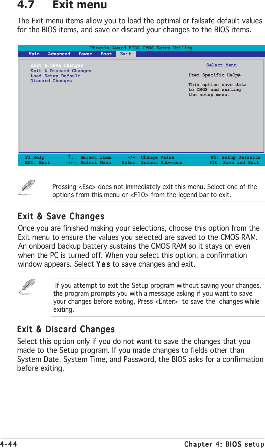
![ASUS A8V-E DeluxeASUS A8V-E DeluxeASUS A8V-E DeluxeASUS A8V-E DeluxeASUS A8V-E Deluxe 4-334-334-334-334-334.5 Power menuThe Power menu items allow you to change the settings for the AdvancedConfiguration and Power Interface (ACPI) and the Advanced PowerManagement (APM). Select an item then press <Enter> to display theconfiguration options.Phoenix-Award BIOS CMOS Setup Utility Main Advanced Power Boot ExitSelect MenuItem Specific HelpSelect the ACPI stateused for SystemSuspend.ACPI Suspend Type [S1&S3]ACPI APIC support [Enabled]APM ConfigurationHardware MonitorF1:Help ↑↓ : Select Item -/+: Change Value F5: Setup DefaultsESC: Exit →←: Select Menu Enter: Select Sub-menu F10: Save and Exit4.5.14.5.14.5.14.5.14.5.1 ACPI Suspend Type [S1&S3]ACPI Suspend Type [S1&S3]ACPI Suspend Type [S1&S3]ACPI Suspend Type [S1&S3]ACPI Suspend Type [S1&S3]Allows you to select the Advanced Configuration and Power Interface(ACPI) state to be used for system suspend.Configuration options: [S1 (POS)] [S3(STR)] [S1&S3]4.5.24.5.24.5.24.5.24.5.2 ACPI APIC Support [Enabled]ACPI APIC Support [Enabled]ACPI APIC Support [Enabled]ACPI APIC Support [Enabled]ACPI APIC Support [Enabled]Allows you to enable or disable the Advanced Configuration and PowerInterface (ACPI) support in the Application-Specific Integrated Circuit(ASIC). When set to Enabled, the ACPI APIC table pointer is included in theRSDT pointer list. Configuration options: [Disabled] [Enabled]](https://usermanual.wiki/ASUSTeK-Computer/MWOM4LA.USERS-MANUAL-2/User-Guide-503729-Page-35.png)
![4-344-344-344-344-34 Chapter 4: BIOS setupChapter 4: BIOS setupChapter 4: BIOS setupChapter 4: BIOS setupChapter 4: BIOS setup4.5.34.5.34.5.34.5.34.5.3 APM ConfigurationAPM ConfigurationAPM ConfigurationAPM ConfigurationAPM ConfigurationF1:Help ↑↓ : Select Item -/+: Change Value F5: Setup DefaultsESC: Exit →←: Select Menu Enter: Select Sub-menu F10: Save and ExitSelect MenuItem Specific HelpWhen Select Password,Please press ENTER keyto change PasswordMax 8 numbers.APM ConfigurationPS2KB Wakeup from S5 [Disabled]PS2MS Wakeup from S5 [Disabled]USB Resume from S3 [Disabled]Power Up On PCI Devices [Disabled]Modem Ring Resume [Disabled]Power On By RTC Alarm [Disabled]xDate (of Month) 0xResume Time (hh:mm:ss) 0 : 0 : 0Restore on AC Power Loss [Power Off]PWR Button < 4 secs [Instant Off]Phoenix-Award BIOS CMOS Setup Utility PowerPS2KB Wakeup from S5 [Disabled]PS2KB Wakeup from S5 [Disabled]PS2KB Wakeup from S5 [Disabled]PS2KB Wakeup from S5 [Disabled]PS2KB Wakeup from S5 [Disabled]Allows you to disable the Power On by PS/2 keyboard function or setspecific keys on the PS/2 keyboard to turn on the system. This featurerequires an ATX power supply that provides at least 1A on the +5VSB lead.Configuration options: [Disabled] [Space Bar] [Ctrl+ESC] [Power Key]PS2MS Wakeup from S5 [Disabled]PS2MS Wakeup from S5 [Disabled]PS2MS Wakeup from S5 [Disabled]PS2MS Wakeup from S5 [Disabled]PS2MS Wakeup from S5 [Disabled]When set to [Enabled], this parameter allows you to use the PS/2 mouseto turn on the system. This feature requires an ATX power supply thatprovides at least 1A on the +5VSB lead. Configuration options: [Disabled][Enabled]Power Up On PCI Devices [Disabled]Power Up On PCI Devices [Disabled]Power Up On PCI Devices [Disabled]Power Up On PCI Devices [Disabled]Power Up On PCI Devices [Disabled]When set to [Enabled], this parameter allows you to turn on the systemthrough a PCI LAN or modem card. This feature requires an ATX powersupply that provides at least 1A on the +5VSB lead.Configuration options: [Disabled] [Enabled]Modem Ring Resume [Disabled]Modem Ring Resume [Disabled]Modem Ring Resume [Disabled]Modem Ring Resume [Disabled]Modem Ring Resume [Disabled]This allows either settings of [Enabled] or [Disabled] for powering up thecomputer when the external modem receives a call while the computer is inSoft-off mode. Configuration options: [Disabled] [Enabled]](https://usermanual.wiki/ASUSTeK-Computer/MWOM4LA.USERS-MANUAL-2/User-Guide-503729-Page-36.png)
![ASUS A8V-E DeluxeASUS A8V-E DeluxeASUS A8V-E DeluxeASUS A8V-E DeluxeASUS A8V-E Deluxe 4-354-354-354-354-35Power On By RTC Alarm [Disabled]Power On By RTC Alarm [Disabled]Power On By RTC Alarm [Disabled]Power On By RTC Alarm [Disabled]Power On By RTC Alarm [Disabled]Allows you to enable or disable RTC to generate a wake event. When thisitem is set to Enabled, the items Date (of Month) and Resume Time(hh:mm:ss) become configurable with set values.Configuration options: [Disabled] [Enabled]Date (of Month) [0]Date (of Month) [0]Date (of Month) [0]Date (of Month) [0]Date (of Month) [0]To set the date of alarm, highlight this item and press <Enter> to displaythe Day of Month Alarm pop-up menu. Key-in a value within the specifiedrange then press <Enter>. Configuration options: [Min=0] [Max=31]Resume Time (hh:mm:ss) 0 : 0 : 0Resume Time (hh:mm:ss) 0 : 0 : 0Resume Time (hh:mm:ss) 0 : 0 : 0Resume Time (hh:mm:ss) 0 : 0 : 0Resume Time (hh:mm:ss) 0 : 0 : 0To set the time of alarm:1. Highlight this item and press <Enter> to display a pop-up menu for thehour field.2. Key-in a value (Min=0, Max=23), then press <Enter>.3. Press <TAB> to move to the minutes field then press <Enter>.4. Key-in a minute value (Min=0, Max=59), then press <Enter>.5. Press <TAB> to move to the seconds field then press <Enter>.6. Key-in a value (Min=0, Max=59), then press <Enter>.Restore on AC Power Loss [Power Off]Restore on AC Power Loss [Power Off]Restore on AC Power Loss [Power Off]Restore on AC Power Loss [Power Off]Restore on AC Power Loss [Power Off]When set to Power Off, the system goes into off state after an AC powerloss. When set to Power On, the system goes on after an AC power loss.When set to Last State, the system goes into either off or on state,whatever the system state was before the AC power loss.Configuration options: [Power Off] [Power On] [Last State]PWR Button < 4 secs [Instant-Off]PWR Button < 4 secs [Instant-Off]PWR Button < 4 secs [Instant-Off]PWR Button < 4 secs [Instant-Off]PWR Button < 4 secs [Instant-Off]Allows you to set the event after the power button is pressed for morethan 4 seconds. Configuration options: [Suspend] [Instant-Off]](https://usermanual.wiki/ASUSTeK-Computer/MWOM4LA.USERS-MANUAL-2/User-Guide-503729-Page-37.png)
![4-364-364-364-364-36 Chapter 4: BIOS setupChapter 4: BIOS setupChapter 4: BIOS setupChapter 4: BIOS setupChapter 4: BIOS setup4.5.44.5.44.5.44.5.44.5.4 Hardware MonitorHardware MonitorHardware MonitorHardware MonitorHardware MonitorThe items in this sub-menu displays the hardware monitor valuesautomatically detected by the BIOS. It also allows you to change CPU Q-Fanfeature-related parameters. Select an item then press <Enter> to displaythe configuration options.F1:Help ↑↓ : Select Item -/+: Change Value F5: Setup DefaultsESC: Exit →←: Select Menu Enter: Select Sub-menu F10: Save and ExitSelect MenuItem Specific HelpHardware MonitorM/B Temperature 34ºC/ 93ºFCurrent CPU1 Temperature 47ºC/118ºFChassis Fan speed 0 RPMCPU Fan speed 4265 RPMChipset Fan speed 7500 RPMChassis Fan2 speed 6367 RPMVCORE Voltage 1.64V+12V Voltage 11.35V+3.3V Voltage 3.36V+5VCC Voltage 5.22VQ-FAN Function [Disabled]xCPU Target Temperature 45ºC/113ºFxTemperature Tolerance 3ºCxMinimum FAN Duty Cycle 11/16xFAN Step Time 0.1 secPhoenix-Award BIOS CMOS Setup Utility PowerM/B TemperatureM/B TemperatureM/B TemperatureM/B TemperatureM/B TemperatureCurrent CPU1 TemperatureCurrent CPU1 TemperatureCurrent CPU1 TemperatureCurrent CPU1 TemperatureCurrent CPU1 TemperatureThe onboard hardware monitor automatically detects and displays themotherboard and CPU temperatures. These items are not user-configurable.Chassis Fan SpeedChassis Fan SpeedChassis Fan SpeedChassis Fan SpeedChassis Fan SpeedCPU Fan SpeedCPU Fan SpeedCPU Fan SpeedCPU Fan SpeedCPU Fan SpeedChipset Fan SpeedChipset Fan SpeedChipset Fan SpeedChipset Fan SpeedChipset Fan SpeedChassis Fan2 SpeedChassis Fan2 SpeedChassis Fan2 SpeedChassis Fan2 SpeedChassis Fan2 SpeedThe onboard hardware monitor automatically detects and displays theChassis, CPU, and Power fan speeds in rotations per minute (RPM). If thefan is not connected to the motherboard, the field shows 0. These itemsare not user-configurable.VCORE Voltage, +12V Voltage, 3.3V Voltage, 5VCCVCORE Voltage, +12V Voltage, 3.3V Voltage, 5VCCVCORE Voltage, +12V Voltage, 3.3V Voltage, 5VCCVCORE Voltage, +12V Voltage, 3.3V Voltage, 5VCCVCORE Voltage, +12V Voltage, 3.3V Voltage, 5VCCVoltageVoltageVoltageVoltageVoltageThe onboard hardware monitor automatically detects the voltage outputthrough the onboard voltage regulators. These items are notuser-configurable.Q-FAN Function [Disabled]Q-FAN Function [Disabled]Q-FAN Function [Disabled]Q-FAN Function [Disabled]Q-FAN Function [Disabled]Allows you to disable or enable the ASUS Q-Fan function.Configuration options: [Disabled] [Enabled]](https://usermanual.wiki/ASUSTeK-Computer/MWOM4LA.USERS-MANUAL-2/User-Guide-503729-Page-38.png)
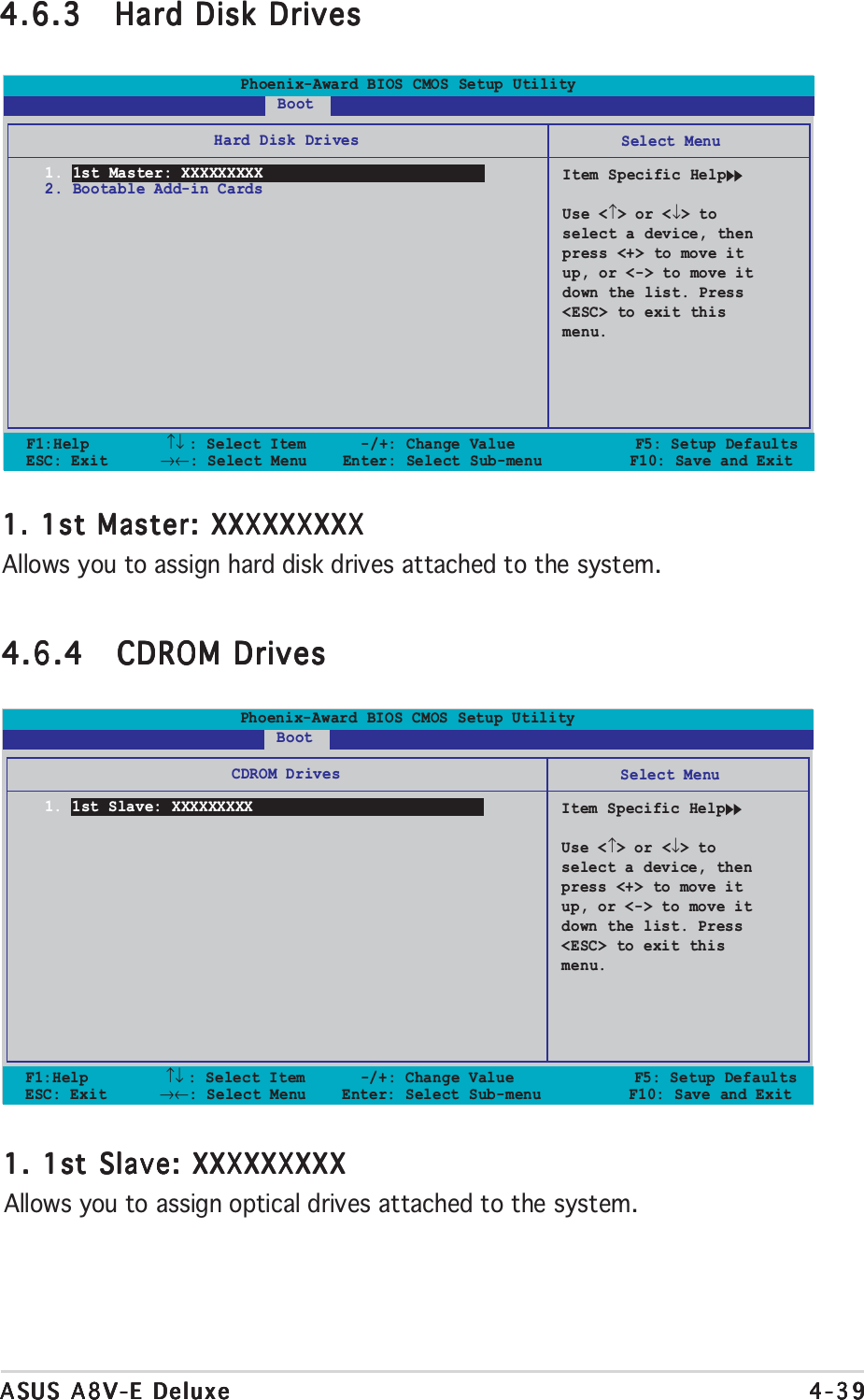
![ASUS A8V-E DeluxeASUS A8V-E DeluxeASUS A8V-E DeluxeASUS A8V-E DeluxeASUS A8V-E Deluxe 4-374-374-374-374-37CPU Target Temperature [xxxºC/xxxºF]CPU Target Temperature [xxxºC/xxxºF]CPU Target Temperature [xxxºC/xxxºF]CPU Target Temperature [xxxºC/xxxºF]CPU Target Temperature [xxxºC/xxxºF]Allows you to set the CPU Q-Fan temperature threshold when the CPU fanspeed is increased to lower the CPU temperature.Configuration options: [10ºC/50ºF] [15ºC/59ºF] [20ºC/68ºF] [25ºC/77ºF][30ºC/86ºF] [35ºC/95ºF] [40ºC/104ºF] [45ºC/113ºF] [50ºC/122ºF][55ºC/131ºF] [60ºC/140ºF] [65ºC/149ºF] [70ºC/158ºF] [75ºC/167ºF][80ºC/176ºF] [85ºC/185ºF]Temperature Tolerance [3ºC]Temperature Tolerance [3ºC]Temperature Tolerance [3ºC]Temperature Tolerance [3ºC]Temperature Tolerance [3ºC]Allows you to set the CPU temperature tolerance value.Configuration options: [0ºC] [1ºC] [2ºC] [3ºC] [4ºC] [5ºC] [6ºC] [7ºC]Minimum FAN Duty Cycle [11/16]Minimum FAN Duty Cycle [11/16]Minimum FAN Duty Cycle [11/16]Minimum FAN Duty Cycle [11/16]Minimum FAN Duty Cycle [11/16]Allows you to set the minimum fan duty cycle.Configuration options: [11/16] [12/16] [13/16] [14/16] [15/16]FAN Step Time [0.1 sec]FAN Step Time [0.1 sec]FAN Step Time [0.1 sec]FAN Step Time [0.1 sec]FAN Step Time [0.1 sec]Allows you to select the fan speed time interval. Configuration options:[0.1 sec] [0.2 sec] [0.3 sec] [0.4 sec] [0.5 sec] [0.6 sec] [0.7 sec][0.8 sec] [0.9 sec] [1.0 sec] [1.1 sec] [1.2 sec] [1.3 sec] [1.4 sec][1.5 sec] [1.6 sec]4.6 Boot menuThe Boot menu items allow you to change the system boot options. Selectan item then press <Enter> to display the sub-menu.Phoenix-Award BIOS CMOS Setup Utility Main Advanced Power Boot ExitSelect MenuItem Specific HelpBoot Device PriorityRemovable DrivesHard Disk DrivesCDROM DrivesBoot Settings ConfigurationSecurityF1:Help ↑↓ : Select Item -/+: Change Value F5: Setup DefaultsESC: Exit →←: Select Menu Enter: Select Sub-menu F10: Save and Exit](https://usermanual.wiki/ASUSTeK-Computer/MWOM4LA.USERS-MANUAL-2/User-Guide-503729-Page-39.png)
![4-384-384-384-384-38 Chapter 4: BIOS setupChapter 4: BIOS setupChapter 4: BIOS setupChapter 4: BIOS setupChapter 4: BIOS setup4.6.14.6.14.6.14.6.14.6.1 Boot Device PriorityBoot Device PriorityBoot Device PriorityBoot Device PriorityBoot Device Priority1st ~ xxth Boot Device [Removable]1st ~ xxth Boot Device [Removable]1st ~ xxth Boot Device [Removable]1st ~ xxth Boot Device [Removable]1st ~ xxth Boot Device [Removable]These items specify the boot device priority sequence from the availabledevices. The number of device items that appears on the screen dependson the number of devices installed in the system.Configuration options: [xxxxx Drive] [Disabled]F1:Help ↑↓ : Select Item -/+: Change Value F5: Setup DefaultsESC: Exit →←: Select Menu Enter: Select Sub-menu F10: Save and ExitSelect MenuItem Specific HelpSelect your bootdevice priorityBoot Device Priority1st Boot Device [Removable]2nd Boot Device [Hard Disk]3rd Boot Device [CDROM]4th Boot Device [Disabled]Phoenix-Award BIOS CMOS Setup Utility Power4.6.24.6.24.6.24.6.24.6.2 Removable DrivesRemovable DrivesRemovable DrivesRemovable DrivesRemovable Drives1. Floppy Disks1. Floppy Disks1. Floppy Disks1. Floppy Disks1. Floppy DisksAllows you to assign a removable drive attached to the system.F1:Help ↑↓ : Select Item -/+: Change Value F5: Setup DefaultsESC: Exit →←: Select Menu Enter: Select Sub-menu F10: Save and ExitSelect MenuItem Specific HelpUse <↑> or <↓> toselect a device, thenpress <+> to move itup, or <-> to move itdown the list. Press<ESC> to exit thismenu.Removable Drives1. Floppy DisksPhoenix-Award BIOS CMOS Setup Utility Boot](https://usermanual.wiki/ASUSTeK-Computer/MWOM4LA.USERS-MANUAL-2/User-Guide-503729-Page-40.png)
![4-404-404-404-404-40 Chapter 4: BIOS setupChapter 4: BIOS setupChapter 4: BIOS setupChapter 4: BIOS setupChapter 4: BIOS setupThe items Typematic Rate (Chars/Sec)Typematic Rate (Chars/Sec)Typematic Rate (Chars/Sec)Typematic Rate (Chars/Sec)Typematic Rate (Chars/Sec) and Typematic DelayTypematic DelayTypematic DelayTypematic DelayTypematic Delay(Msec)(Msec)(Msec)(Msec)(Msec) becomes user-configurable only when the item Typematic RateSetting is enabled.4.6.54.6.54.6.54.6.54.6.5 Boot Settings ConfigurationBoot Settings ConfigurationBoot Settings ConfigurationBoot Settings ConfigurationBoot Settings ConfigurationF1:Help ↑↓ : Select Item -/+: Change Value F5: Setup DefaultsESC: Exit →←: Select Menu Enter: Select Sub-menu F10: Save and ExitSelect MenuItem Specific HelpPress [Enter] toenable or disable.Boot Settings ConfigurationCase Open Warning [Enabled]Quick Boot [Enabled]Boot Up Floppy Seek [Enabled]Bootup Num-Lock [On]Typematic Rate Setting [Disabled]xTypematic Rate (Chars/Sec) 6xTypematic Delay (Msec) 250OS Select For DRAM > 64MB [Non-OS2]Full Screen LOGO [Enabled]Halt On [All, But Keyboard]Phoenix-Award BIOS CMOS Setup Utility BootCase Open Warning [Enabled]Case Open Warning [Enabled]Case Open Warning [Enabled]Case Open Warning [Enabled]Case Open Warning [Enabled]Enables or disables the chassis open status feature. Setting to Enabled,clears the chassis open status. Configuration options: [Disabled] [Enabled]Quick Boot [Enabled]Quick Boot [Enabled]Quick Boot [Enabled]Quick Boot [Enabled]Quick Boot [Enabled]Enables or disables the quick boot feature. When Enabled, the system skipscertain tests while booting. Configuration options: [Disabled] [Enabled]Boot Up Floppy Seek [Enabled]Boot Up Floppy Seek [Enabled]Boot Up Floppy Seek [Enabled]Boot Up Floppy Seek [Enabled]Boot Up Floppy Seek [Enabled]Enables or disables the chassis open status feature. Setting to Enabled,clears the chassis open status. Configuration options: [Disabled] [Enabled]Bootup Num-Lock [On]Bootup Num-Lock [On]Bootup Num-Lock [On]Bootup Num-Lock [On]Bootup Num-Lock [On]Allows you to select the power-on state for the NumLock.Configuration options: [Off] [On]Typematic Rate Setting [Disabled]Typematic Rate Setting [Disabled]Typematic Rate Setting [Disabled]Typematic Rate Setting [Disabled]Typematic Rate Setting [Disabled]Allows you to set the keystroke rate. Enable this item to configure theTypematic Rate (Chars/Sec) Typematic Rate (Chars/Sec) Typematic Rate (Chars/Sec) Typematic Rate (Chars/Sec) Typematic Rate (Chars/Sec) and the Typematic Delay (Msec)Typematic Delay (Msec)Typematic Delay (Msec)Typematic Delay (Msec)Typematic Delay (Msec).Configuration options: [Disabled] [Enabled]](https://usermanual.wiki/ASUSTeK-Computer/MWOM4LA.USERS-MANUAL-2/User-Guide-503729-Page-42.png)
![ASUS A8V-E DeluxeASUS A8V-E DeluxeASUS A8V-E DeluxeASUS A8V-E DeluxeASUS A8V-E Deluxe 4-414-414-414-414-41Typematic Rate (Chars/Sec) [6]Typematic Rate (Chars/Sec) [6]Typematic Rate (Chars/Sec) [6]Typematic Rate (Chars/Sec) [6]Typematic Rate (Chars/Sec) [6]Allows you to select the rate at which a character repeats when you hold akey. Configuration options: [6] [8] [10] [12] [15] [20] [24] [30]Typematic Delay (Msec) [250]Typematic Delay (Msec) [250]Typematic Delay (Msec) [250]Typematic Delay (Msec) [250]Typematic Delay (Msec) [250]Allows you to set the delay before keystrokes begin to repeat.Configuration options: [250] [500] [750] [1000]OS Select for DRAM > 64MB [Non-OS2]OS Select for DRAM > 64MB [Non-OS2]OS Select for DRAM > 64MB [Non-OS2]OS Select for DRAM > 64MB [Non-OS2]OS Select for DRAM > 64MB [Non-OS2]Set this item to OS2 only when you are running on an OS/2 operatingsystem with an installed RAM of greater than 64 KB.Configuration options: [Non-OS2] [OS2]Full Screen LOGO [Enabled]Full Screen LOGO [Enabled]Full Screen LOGO [Enabled]Full Screen LOGO [Enabled]Full Screen LOGO [Enabled]Allows you to enable or disable the full screen logo display feature.Configuration options: [Disabled] [Enabled]Make sure that the above item is set to [Enabled] if you want to use theASUS MyLogo2™ feature.Halt On [All, But Keyboard]Halt On [All, But Keyboard]Halt On [All, But Keyboard]Halt On [All, But Keyboard]Halt On [All, But Keyboard]Allows you to error report type.Configuration options: [All Errors] [No Errors] [All, But Keyboard][All, But Diskette] [All, But Disk/Key]](https://usermanual.wiki/ASUSTeK-Computer/MWOM4LA.USERS-MANUAL-2/User-Guide-503729-Page-43.png)
![4-424-424-424-424-42 Chapter 4: BIOS setupChapter 4: BIOS setupChapter 4: BIOS setupChapter 4: BIOS setupChapter 4: BIOS setup4.6.64.6.64.6.64.6.64.6.6 SecuritySecuritySecuritySecuritySecurityF1:Help ↑↓ : Select Item -/+: Change Value F5: Setup DefaultsESC: Exit →←: Select Menu Enter: Select Sub-menu F10: Save and ExitSelect MenuItem Specific HelpSupervisor passwordcontrols full access,<Enter> to changepassword.Boot Settings ConfigurationSupervisor Password ClearUser Password ClearPassword Check [Setup]Phoenix-Award BIOS CMOS Setup Utility BootSupervisor PasswordSupervisor PasswordSupervisor PasswordSupervisor PasswordSupervisor PasswordUser PasswordUser PasswordUser PasswordUser PasswordUser PasswordThese fields allow you to set passwords:To set a password:1. Select an item then press <Enter>.2. Type in a password using a combination of a maximum of eight (8)alpha-numeric characters, then press <Enter>.3. When prompted, confirm the password by typing the exact charactersagain, then press <Enter>. The password field setting is changed toSet.To clear the password:1. Select the password field and press <Enter> twice. The followingmessage appears:PASSWORD DISABLED !!!Press any key to continue...2. Press any key to continue. The password field setting is changed toClear.](https://usermanual.wiki/ASUSTeK-Computer/MWOM4LA.USERS-MANUAL-2/User-Guide-503729-Page-44.png)
![ASUS A8V-E DeluxeASUS A8V-E DeluxeASUS A8V-E DeluxeASUS A8V-E DeluxeASUS A8V-E Deluxe 4-434-434-434-434-43A note about passwordsA note about passwordsA note about passwordsA note about passwordsA note about passwordsThe Supervisor password is required to enter the BIOS Setup programpreventing unauthorized access. The User password is required toboot the system preventing unauthorized use.Forgot your password?Forgot your password?Forgot your password?Forgot your password?Forgot your password?If you forget your password, you can clear it by erasing the CMOS RealTime Clock (RTC) RAM. The RAM data containing the passwordinformation is powered by the onboard button cell battery. If you needto erase the CMOS RAM, refer to section “2.6 Jumpers” forinstructions.Password CheckPassword CheckPassword CheckPassword CheckPassword CheckThis field requires you to enter the password before entering the BIOSsetup or the system. Select [Setup] to require the password beforeentering the BIOS Setup. Select [System] to require the password beforeentering the system. Configuration options: [Setup] [System]](https://usermanual.wiki/ASUSTeK-Computer/MWOM4LA.USERS-MANUAL-2/User-Guide-503729-Page-45.png)
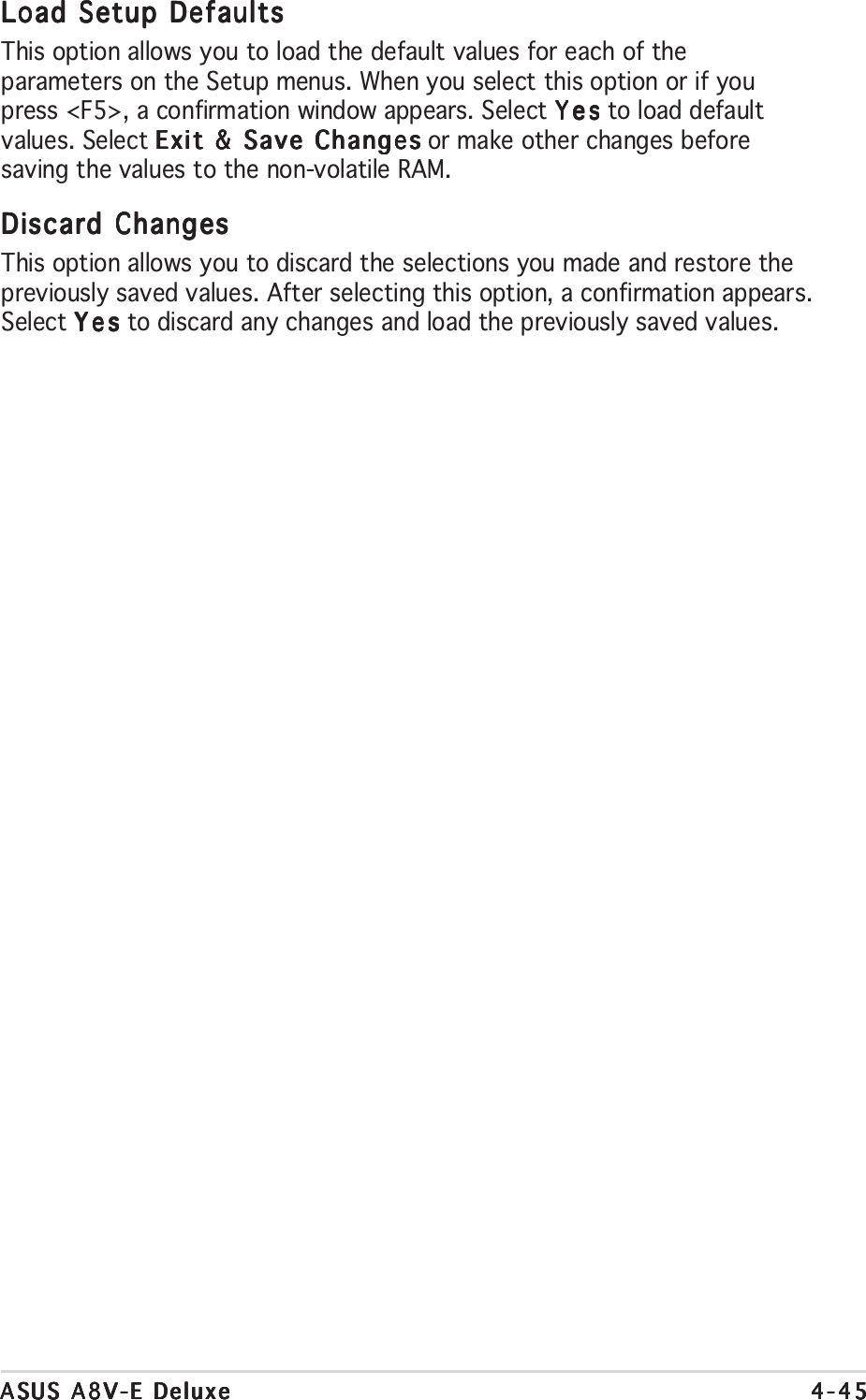

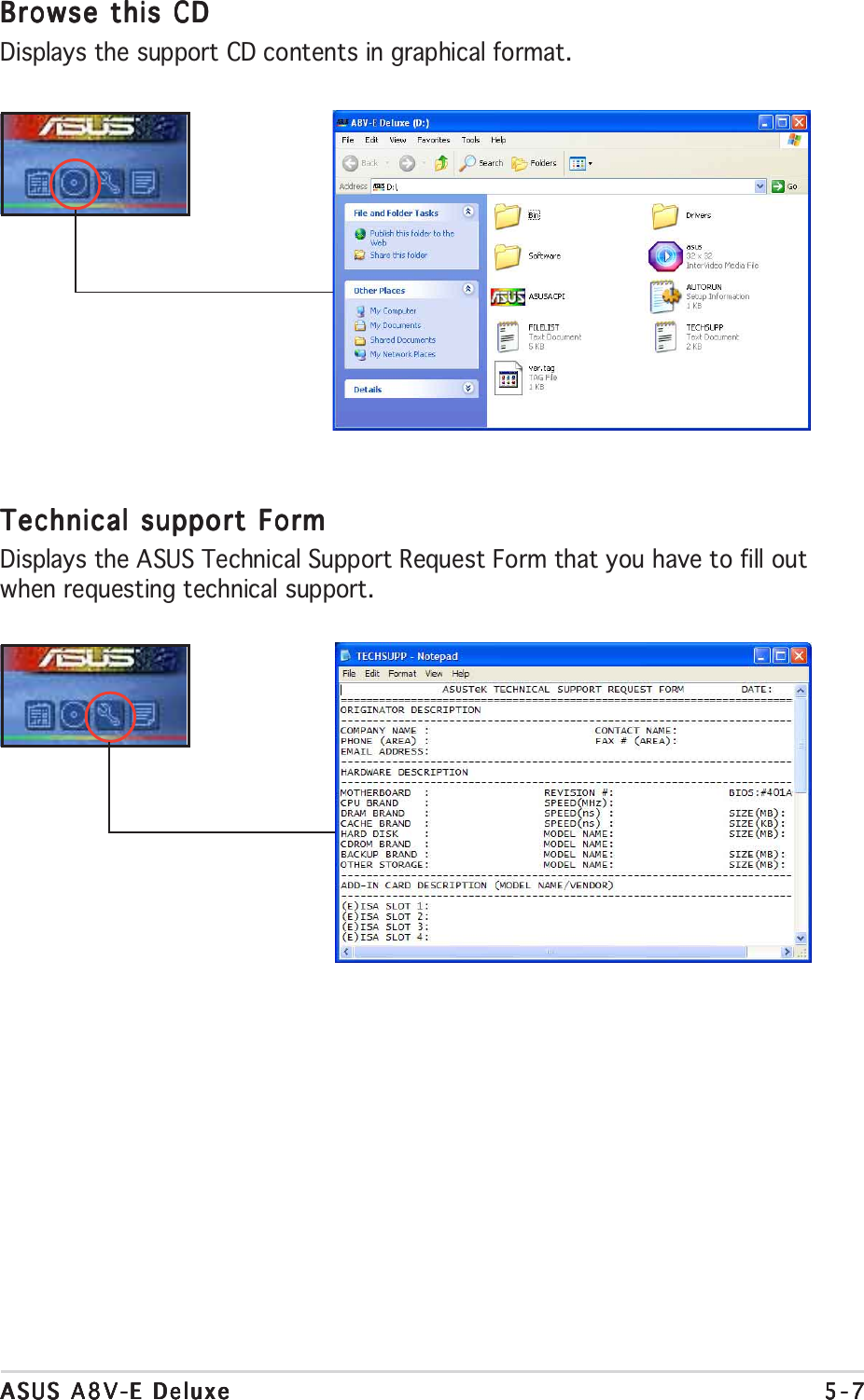
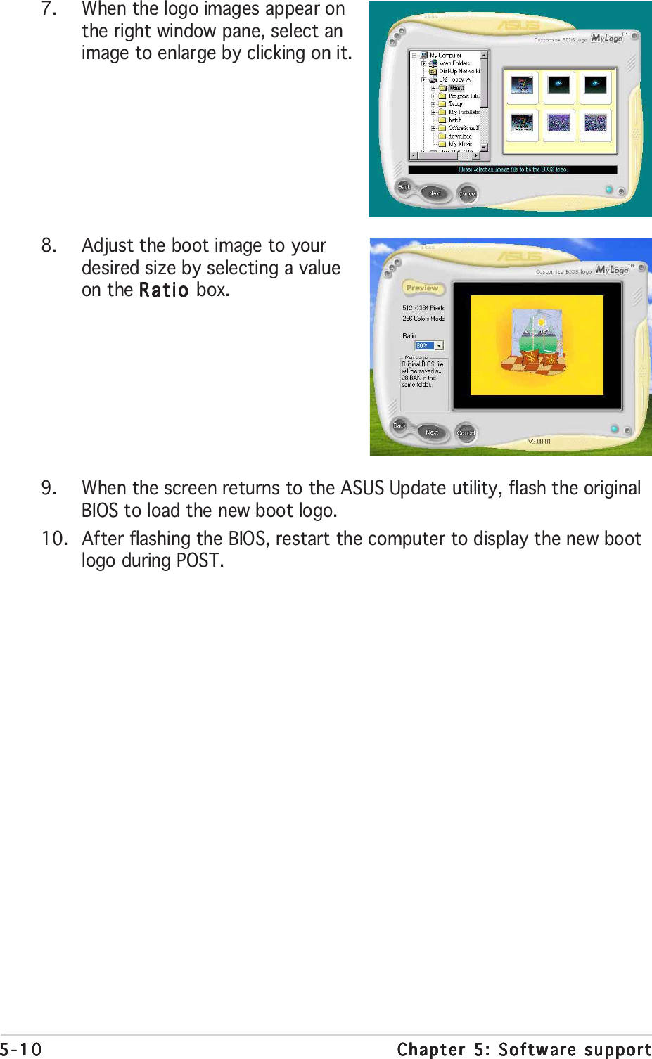
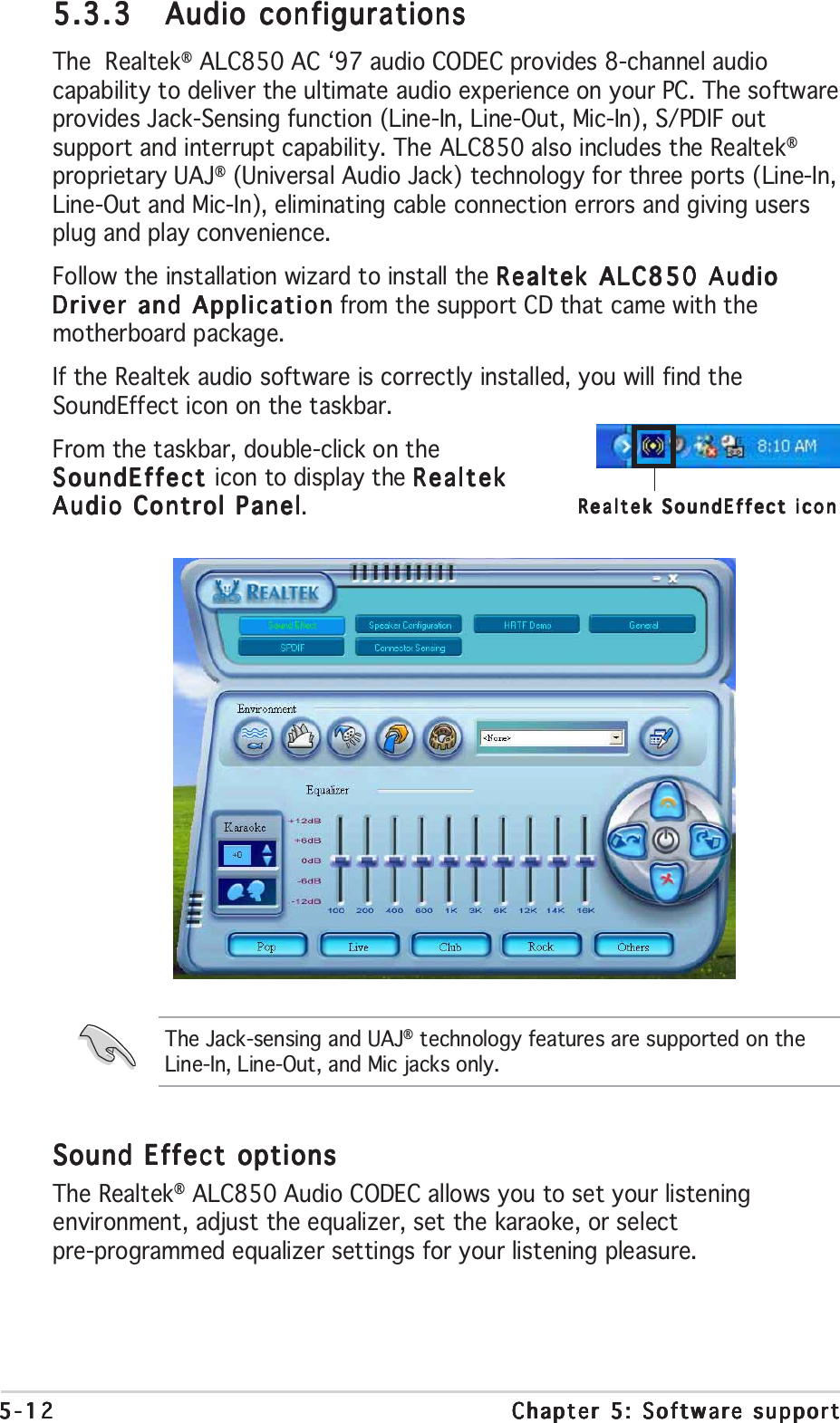
![ASUS A8V-E DeluxeASUS A8V-E DeluxeASUS A8V-E DeluxeASUS A8V-E DeluxeASUS A8V-E Deluxe 5-95-95-95-95-95.3 Software informationMost of the applications in the support CD have wizards that willconveniently guide you through the installation. View the online help orreadme file that came with the software application for more information.5.3.15.3.15.3.15.3.15.3.1 ASUS MyLogo2™ASUS MyLogo2™ASUS MyLogo2™ASUS MyLogo2™ASUS MyLogo2™The ASUS MyLogo2™ utility lets you customize the boot logo. The bootlogo is the image that appears on screen during the Power-On Self-Tests(POST). The ASUS MyLogo2™ is automatically installed when you install theASUS Update ASUS Update ASUS Update ASUS Update ASUS Update utility from the support CD. See section “5.2.3 Utilitiesmenu” for details.To launch the ASUS MyLogo2™:1. Launch the ASUS Update utility. Refer to section “4.1.5 ASUS Updateutility” for details.2. Select Options Options Options Options Options from the drop down menu, then click NextNextNextNextNext.3. Check the option Launch MyLogo to replace system bootLaunch MyLogo to replace system bootLaunch MyLogo to replace system bootLaunch MyLogo to replace system bootLaunch MyLogo to replace system bootlogo before flashing BIOSlogo before flashing BIOSlogo before flashing BIOSlogo before flashing BIOSlogo before flashing BIOS, then click NextNextNextNextNext.4. Select Update BIOS from a fileUpdate BIOS from a fileUpdate BIOS from a fileUpdate BIOS from a fileUpdate BIOS from a file from the drop down menu, thenclick NextNextNextNextNext.5. When prompted, locate the newBIOS file, then click NextNextNextNextNext. TheASUS MyLogo2 window appears.6. From the left window pane, selectthe folder that contains the imageyou intend to use as your bootlogo.• Before using the ASUS MyLogo2™, use the AWDFLASH utility tomake a copy of your original BIOS file, or obtain the latest BIOSversion from the ASUS website. See section “4.1.2 Updating theBIOS”.•Make sure that the BIOS item Full Screen Logo Full Screen Logo Full Screen Logo Full Screen Logo Full Screen Logo is set to[Enabled] if you wish to use ASUS MyLogo2.See section “4.6.5 Boot Settings Configuration”.•You can create your own boot logo image in GIF, JPG, or BMP fileformats.](https://usermanual.wiki/ASUSTeK-Computer/MWOM4LA.USERS-MANUAL-2/User-Guide-503729-Page-59.png)
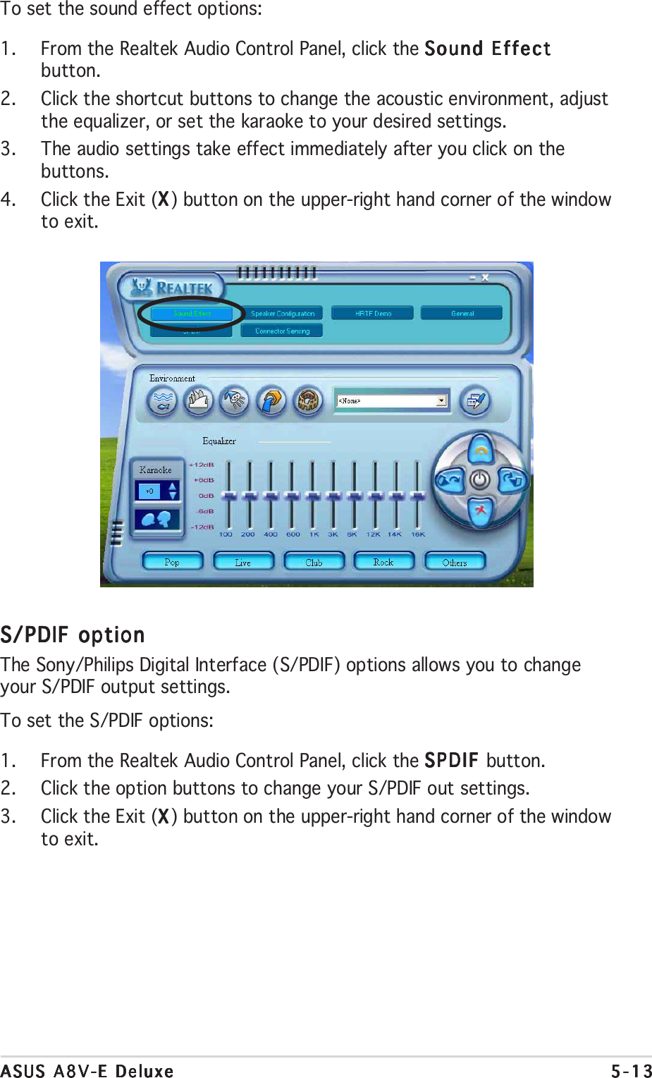
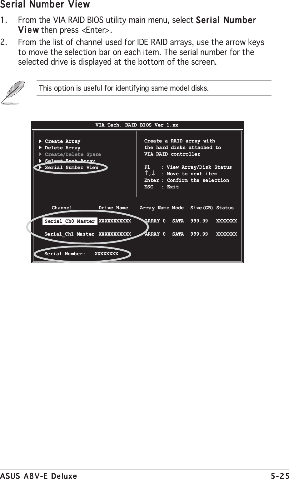
![5-245-245-245-245-24 Chapter 5: Software supportChapter 5: Software supportChapter 5: Software supportChapter 5: Software supportChapter 5: Software supportDelete ArrayDelete ArrayDelete ArrayDelete ArrayDelete Array1. From the VIA RAID BIOS utility main menu, select Delete ArrayDelete ArrayDelete ArrayDelete ArrayDelete Array thenpress <Enter>.3. Press <Y> to confirm or <N> to return to the configuration options.The selected array will be destroyed.Are you sure? Continue? Press Y/N10. Press <Y> to confirm or <N> to return to the configuration options.11. Press <Esc> to go back to main menu.Select Boot ArraySelect Boot ArraySelect Boot ArraySelect Boot ArraySelect Boot Array1. From the VIA RAID BIOS utility main menu, select Select BootSelect BootSelect BootSelect BootSelect BootArrayArrayArrayArrayArray then press <Enter>.2. From the list of channel used for IDE RAID arrays, press <Enter> toselect a RAID array for boot. After selection, the StatusStatusStatusStatusStatus of theselected array will change to Boot.3. Press <ESC> to return to the menu items. Follow the same procedureto deselect the the boot array.2. From the list of channel used for IDE RAID arrays, press <Enter><Enter><Enter><Enter><Enter> toselect a RAID array to delete. The following confirmation messageappears. Create Array Delete Array Create/Delete Spare Select Boot Array Serial Number ViewVIA Tech. RAID BIOS Ver 1.xxCreate a RAID array withthe hard disks attached toVIA RAID controllerF1 : View Array/Disk Status↑,↓: Move to next itemEnter : Confirm the selectionESC : Exit Channel Drive Name Array Name Mode Size(GB) Status [ ]Serial_Ch0 Master XXXXXXXXXXX ARRAY 0 SATA 999.99 XXXXXXX [ ]Serial_Ch1 Master XXXXXXXXXXX ARRAY 0 SATA 999.99 XXXXXXX](https://usermanual.wiki/ASUSTeK-Computer/MWOM4LA.USERS-MANUAL-2/User-Guide-503729-Page-74.png)