ASUSTeK Computer R1F Notebook PC User Manual rev 2
ASUSTeK Computer Inc Notebook PC rev 2
UserManual.wiki
>
ASUSTeK Computer
>
R1F User Manual
>
user manual rev 2
Contents
1.
User Manual WLAN 1
2.
User Manual WLAN 2
3.
User Manual 1
4.
User Manual 2
5.
User manual WLAN 1
6.
User manual WLAN 2
7.
User manual 1
8.
User manual 2
9.
Revised user manual part 1
10.
Revised user manual part 2
11.
user manual rev 1
12.
user manual rev 2
13.
user manual 1 rev
14.
user manual 2 rev
user manual rev 2
Navigation menu
Upload a User Manual
Namespaces
Wiki Guide
HTML
PDF
Info
Views
User Manual
Discussion / Help
Navigation
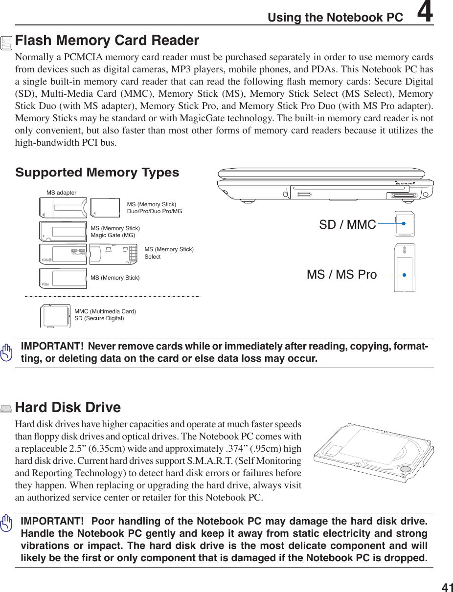
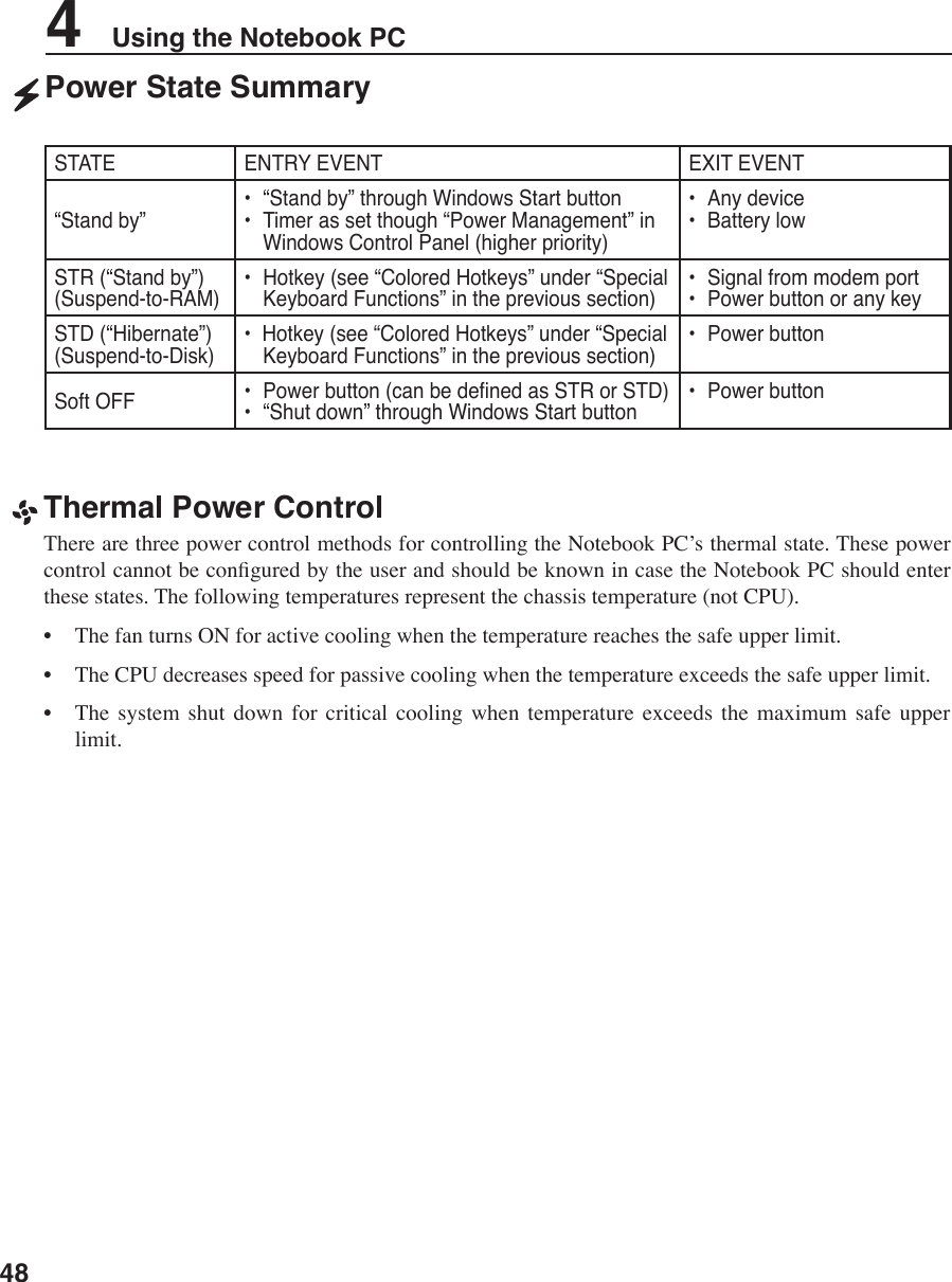
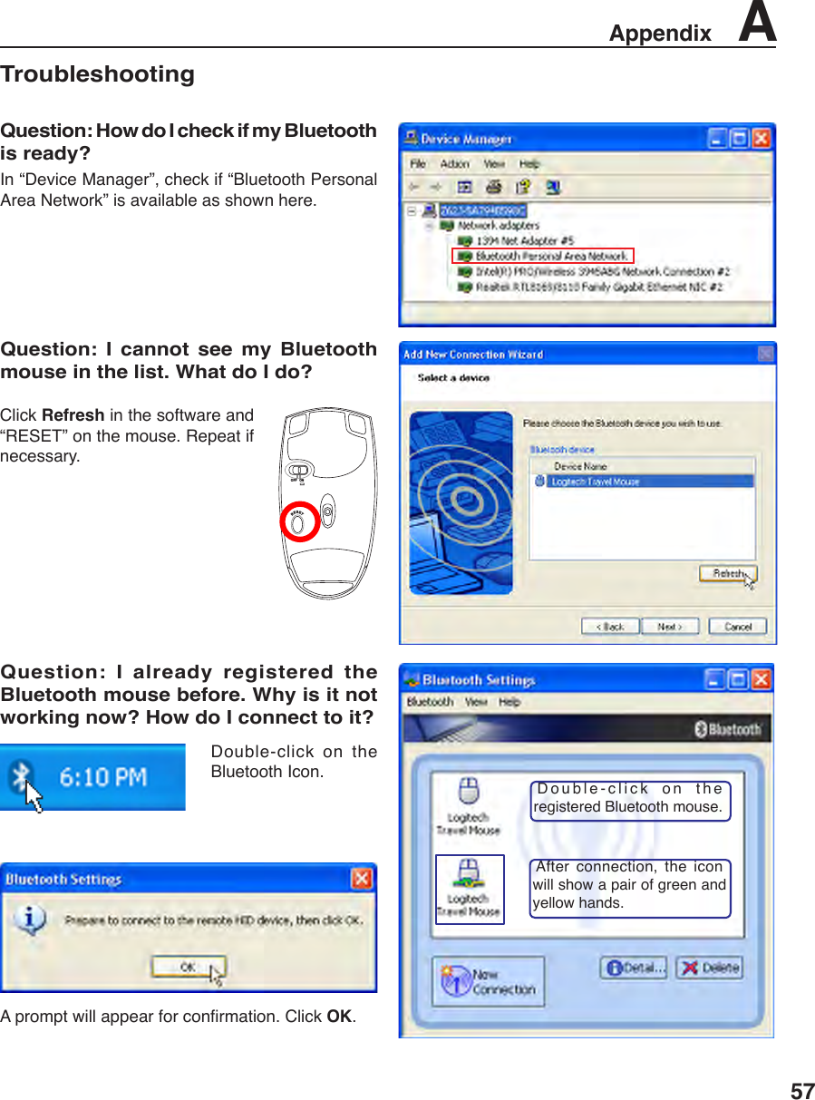
![47Using the Notebook PC 4Power Management ModesThe Notebook PC has a number of automatic or adjustable power saving features that you can use to maximize battery life and lower Total Cost of Ownership (TCO). You can control some of these features through the Power menu in the BIOS Setup. ACPI power management settings are made through the operating system. The power management features are designed to save as much electricity as possible by putting components into a low power consumption mode as often as possible but also allow full operation on demand. These low power modes are referred to as “Stand by” (or Suspend-to-RAM) and “Hibernation” mode or Suspend-to-Disk (STD). The Standby mode is a simple function provided by the operating system. When the Notebook PC is in either one of the power saving modes, the status will be shown by the following: “Stand by”: Power LED Blinks and “Hibernation”: Power LED OFF.Full Power Mode & Maximum PerformanceThe Notebook PC operates in Full Power mode when the power management function is disabled by conguring Windows power management and SpeedStep. When the Notebook PC is operating in Full Power Mode, the Power LED remains ON. If you are conscious of both system performance and power consumption, select “Maximum Performance” instead of disabling all power management features.ACPIAdvanced Conguration and Power Management (ACPI) was developed by Intel, Microsoft, and Toshiba especially for Windows and later to control power management and Plug and Play features. ACPI is the new standard in power management for Notebook PCs. NOTE: APM was used in older operating systems like Windows NT4 and Windows 98. Because newer operating systems like Windows XP, Windows 2000, and Windows ME utilize ACPI, APM is no longer fully supported on this Notebook PC.Suspend ModeIn “Stand by” (STR) and “Hibernation” (STD), the CPU clock is stopped and most of the Notebook PC devices are put in their lowest active state. The suspend mode is the lowest power state of the Notebook PC. The Notebook PC enters suspend mode when the system remains idle for a specied amount of time or manually using the [Fn][F1] keys. The Power LED blinks when the Notebook PC is in STR mode. In STD mode, the Notebook PC will appear to be powered OFF. Recover from STR by pressing any keyboard button (except Fn). Recover from STD by using the power switch (just like powering ON the Notebook PC).Power SavingsIn addition to reducing the CPU clock, this mode puts devices including the LCD backlight in their lower active state. The Notebook PC enters “Stand by” mode (low priority) when the system remains idle for a specied amount of time. The time-out can be set through Windows power management (higher priority). To resume system operation, press any key.](https://usermanual.wiki/ASUSTeK-Computer/R1F.user-manual-rev-2/User-Guide-661173-Page-7.png)
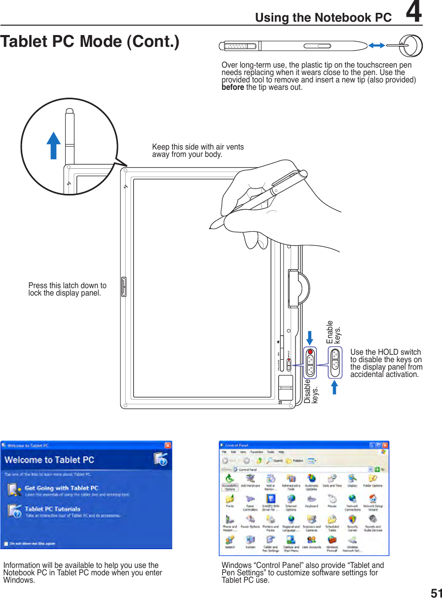

![Appendix A 66 CE Mark Warning This is a Class B product, in a domestic environment, this product may cause radio interference, in which case the user may be required to take adequate measures. FCC Radio Frequency Interference Requirements This device is restricted to INDOOR USE due to its operation in the 5.15 to 5.25GHz frequency range. FCC requires this product to be used indoors for the frequency range 5.15 to 5.25GHz to reduce the potential for harmful interference to co-channel of the Mobile Satellite Systems. High power radars are allocated as primary user of the 5.25 to 5.35GHz and 5.65 to 5.85GHz bands. These radar stations can cause interference with and / or damage this device. IMPORTANT: This device and its antenna(s) must not be co-located or operating in conjunction with any other antenna or transmitter. FCC Radio Frequency (RF) Exposure Caution Statement FCC Caution: Any changes or modifications not expressly approved by the party responsible for compliance could void the user’s authority to operate this equipment. “ASUS declare that this device in the 2.4GHz is limited to Channels 1 through 11 by specified firmware controlled in the USA.” This equipment complies with FCC RF exposure limits set forth for an uncontrolled environment. To maintain compliance with FCC RF exposure compliance requirements, please follow operation instruction in the user’s manual. For operation within 5.15 GHz and 5.25GHz frequency ranges, it is restricted to indoor environment only. IC Radiation Exposure Statement This equipment complies with IC radiation exposure limits set forth for an uncontrolled environment. To maintain compliance with IC RF exposure compliance requirements, please avoid direct contact to the transmitting antenna during transmitting. End users must follow the specific operating instructions for satisfying RF exposure compliance. Declaration of Conformity (R&TTE directive 1999/5/EC) The following items were completed and are considered relevant and sufficient: • Essential requirements as in [Article 3] • Protection requirements for health and safety as in [Article 3.1a] • Testing for electric safety according to [EN 60950] • Protection requirements for electromagnetic compatibility in [Article 3.1b] • Testing for electromagnetic compatibility in [EN 301 489-1] & [EN 301] • Testing according to [489-17] • Effective use of the radio spectrum as in [Article 3.2] • Radio test suites according to [EN 300 328-2]](https://usermanual.wiki/ASUSTeK-Computer/R1F.user-manual-rev-2/User-Guide-661173-Page-26.png)