ASUSTeK Computer R2E Ultra Mobile PC (UMPC) User Manual R2E USerMan part1
ASUSTeK Computer Inc Ultra Mobile PC (UMPC) R2E USerMan part1
Contents
Part 1
UltraMobilePC (UMPC)
Hardware User’s Manual
E3357 / Jul 2007
1.3M
PIXELS
1.3M
PIXELS

2
UltraMobilePC
Table of Contents
1. Introducing the UltraMobilePC
About This User’s Manual .......................................................................... 6
Notes For This Manual........................................................................... 6
Safety Precautions ..................................................................................... 7
Transportation Precautions .................................................................. 8
Preparing your UltraMobilePC.................................................................... 9
2. Knowing the Parts
Front Side................................................................................................. 12
Right Side................................................................................................. 14
Top Side.................................................................................................... 16
Left Side ................................................................................................... 18
Bottom Side.............................................................................................. 19
Back Side ................................................................................................. 20
3. Getting Started
Power System .......................................................................................... 24
Using AC Power .................................................................................. 24
Using Battery Power ............................................................................ 25
Battery Care......................................................................................... 25
Powering ON the UltraMobilePC ......................................................... 26
The Power-On Self Test (POST).......................................................... 26
Checking Battery Power ...................................................................... 27
Charging the Battery Pack................................................................... 28
Power Options ..................................................................................... 28
Power Management Modes................................................................. 29
Sleep and Hibernate ............................................................................ 29
Thermal Power Control........................................................................ 29
Status Indicators....................................................................................... 30
Table of Contents

UltraMobilePC
3
4. Using the UltraMobilePC
Display Calibration ................................................................................... 32
MS Windows Vista............................................................................... 32
MS Windows XP .................................................................................. 33
Connections.............................................................................................. 34
Network Connection ............................................................................ 34
Wireless LAN Connection (on selected models) ................................. 35
Windows Wireless Network Connection .............................................. 36
ASUS Wireless LAN (on selected models)......................................... 38
Bluetooth Wireless Connection (on selected models) ......................... 40
Operating System and Software............................................................... 41
Fingerprint Registration (on selected models) ..................................... 42
GPS Software (USA & Europe only) ............................................ 44
3G Watcher Software (on selected models) ........................................ 45
Appendix
Optional Accessories................................................................................ 50
More Optional Accessories....................................................................... 53
Optional Connections ............................................................................... 54
Glossary ................................................................................................... 57
&HUWLÀFDWLRQs

4
UltraMobilePC

UltraMobilePC
5
1. Introducing the UltraMobilePC
About This User’s Manual
Notes For This Manual
Safety Precautions
Preparing your UltraMobilePC
NOTE: Photos and icons in this manual are used for artistic purposes only and do
not show what is actually used in the product itself.

6
UltraMobilePC
About This User’s Manual
You are reading the UltraMobilePC User’s Manual. This User’s Manual pro-
vides information on the various components in the UltraMobilePC and how
to use them. The following are major sections of this User’s Manuals:
1. Introducing the UltraMobilePC
Introduces you to the UltraMobilePC and this User’s Manual.
2. Knowing the Parts
Gives you information on the UltraMobilePC’s components.
3. Getting Started
Gives you information on getting started with the UltraMobilePC.
4. Using the UltraMobilePC
Gives you information on using the UltraMobilePC’s components.
5. Appendix
Introduces you to optional accessories and gives additional information.
Notes For This Manual
A few notes and warnings in bold are used throughout this guide that you should be aware of
in order to complete certain tasks safely and completely. These notes have different degrees
of importance as described below:
NOTE: Tips and information for special situations.
WARNING! Important information that must be followed for safe operation.
IMPORTANT! Vital information that must be followed to prevent damage to data,
components, or persons.
TIP: Tips and useful information for completing tasks.
UltraMobilePC
7
Safety Precautions
The following safety precautions will increase the life of the UltraMobilePC. Follow all pre-
FDXWLRQVDQGLQVWUXFWLRQV([FHSWDVGHVFULEHGLQWKLVPDQXDOUHIHUDOOVHUYLFLQJWRTXDOLÀHG
personnel. Do not use damaged power cords, accessories, or other peripherals. Do not use
strong solvents such as thinners, benzene, or other chemicals on or near the surface.
IMPORTANT! Disconnect the AC power and remove the battery pack(s) before
cleaning. Wipe the UltraMobilePC using a clean cellulose sponge or chamois cloth
dampened with a solution of nonabrasive detergent and a few drops of warm water
and remove any extra moisture with a dry cloth.
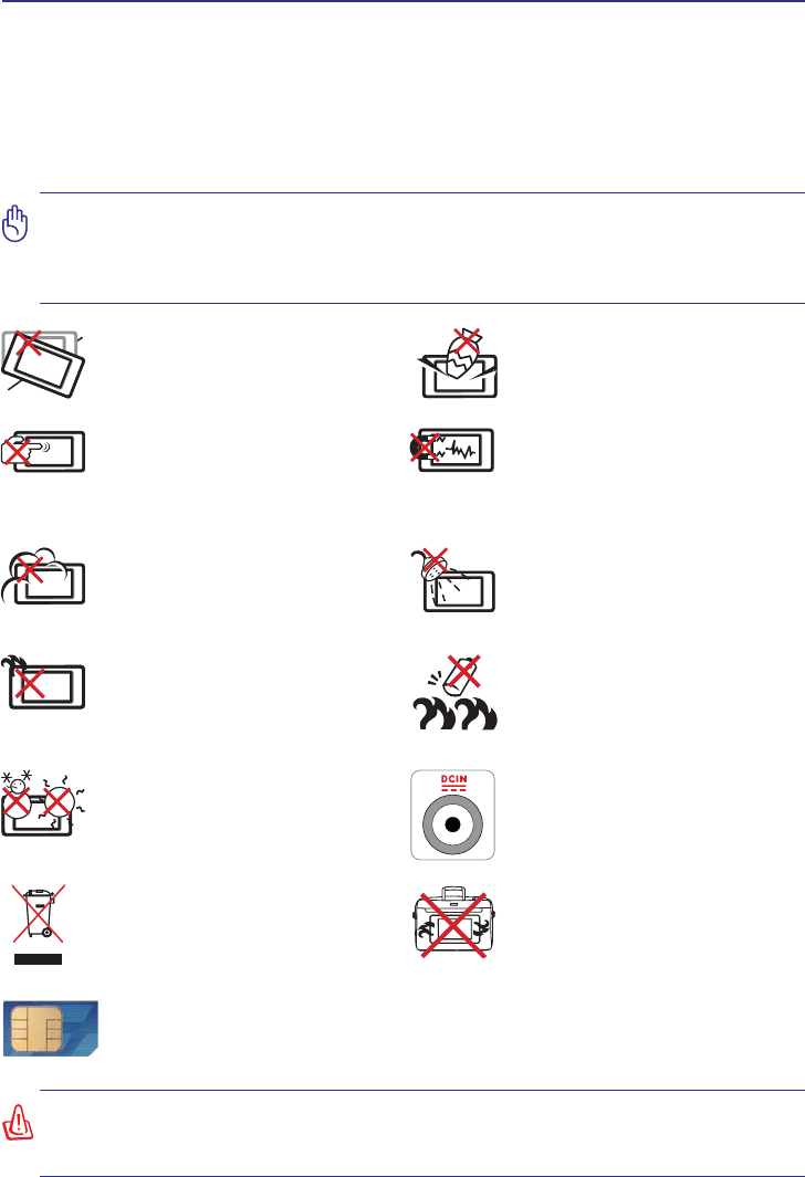
DO NOT expose to or use near liquids,
rain, or moisture. DO NOT use the
modem during an electrical storm.
DO NOT expose to dirty or dusty en-
vironments. DO NOT operate during
a gas leak.
SAFE TEMP: This UltraMobilePC
should only be used in environments
with ambient temperatures between
5°C (41°F) and 35°C (95°F)
Battery safety warning:
DO NOT WKURZWKHEDWWHU\LQÀUH
DO NOT short circuit the contacts.
DO NOT disassemble the battery.
DO NOT expose to strong magnetic
RUHOHFWULFDOÀHOGV
DO NOT place on uneven or unstable
work surfaces. Seek servicing if the
casing has been damaged.
DO NOT place or drop objects on top
and do not shove any foreign objects
into the UltraMobilePC.
DO NOT scratch the display panel.
Do not place together with small items
that may scratch or enter the UltraMo-
bilePC vents.
DO NOT leave the UltraMobilePC
on your lap or any part of the body in
order to prevent discomfort or injury
from heat exposure.
DO NOT throw the UltraMobilePC
in municipal waste. Check local
regulations for disposal of electronic
products.
DO NOT carry or cover a UltraMo-
bilePC that is powered ON with any
materials that will reduce air circula-
tion such as a carrying bag.
INPUT RATING: Refer to the rating
label on the bottom of the UltraMo-
bilePC and be sure that your power
adapter complies with the rating.
(1)
6HHHQGRI6HFWLRQIRUGHÀQLWLRQ
Models with 3G(1): Produces radio wave emissions that may cause electrical
interferences and must be used in places that do not prohibit such devices. Take
precautions while using.
WARNING! The 3G function needs to be switched OFF in areas with potentially
explosive atmospheres such as petrol (gas) stations, chemical storage depots, and
blasting operations.

8
UltraMobilePC
Transportation Precautions
To prepare the UltraMobilePC for transport, you should turn it OFF and disconnect all exter-
nal peripherals to prevent damage to the connectors. The hard disk drive’s head retracts
when the power is turned OFF to prevent scratching of the hard disk surface during transport.
Therefore, you should not transport the UltraMobilePC while the power is still ON.
Cover Your UltraMobilePC
You can purchase an optional carrying case to protect it from dirt, water, shock, and
scratches.
Charge Your Batteries
If you intend to use battery power, be sure to fully charge your battery pack and any optional
battery packs before going on long trips. Remember that the power adapter charges the bat-
tery pack as long as it is plugged into the computer and an AC power source. Be aware that
it takes much longer to charge the battery pack when the UltraMobilePC is in use.
Airplane Precautions
Contact your airline if you want to use the UltraMobilePC on the airplane. Most airlines will
have restrictions for using electronic devices. Most airlines will allow electronic use only
between and not during takeoffs and landings.
CAUTION: The UltraMobilePC’s surface is easily dulled if not properly
cared for. Be careful not to rub or scrape the UltraMobilePC surfaces when
transporting your UltraMobilePC.
CAUTION! There are three main types of airport security devices: X-ray machines
(used on items placed on conveyor belts), magnetic detectors (used on people walking
through security checks), and magnetic wands (hand-held devices used on people or
individual items). You can send your UltraMobilePC and diskettes through airport X-ray
machines. However, it is recommended that you do not send your UltraMobilePC or
diskettes through airport magnetic detectors or expose them to magnetic wands.
UltraMobilePC
9
Preparing your UltraMobilePC
These are only quick instructions for using your UltraMobilePC. Read the later pages for
detailed information on using your UltraMobilePC.
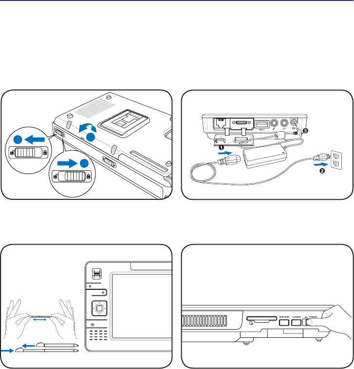
1. Install the battery pack
3. Remove the Tablet Pen 4. Turn ON the UltraMobilePC
2. Connect the AC Power Adapter
Slide the power switch and release.
1
3
2
Extend the Tablet Pen
as shown.
Then Tablet Pen can be inserted in the extended
form and then contracted while pressing the Tablet
3HQÁXVKZLWKWKH8OWUD0RELOH3& The power switch turns ON and OFF the
UltraMobilePC or putting the UltraMobilePC into
sleep or hibernation modes. Actual behavior of
the power switch can be customized in Windows
Control Panel > Power Options > System
Settings.

10
UltraMobilePC

UltraMobilePC
11
2. Knowing the Parts
Basic sides of the UltraMobilePC
NOTE: Photos and icons in this manual are used for artistic purposes only and do
not show what is actually used in the product itself.
12
UltraMobilePC
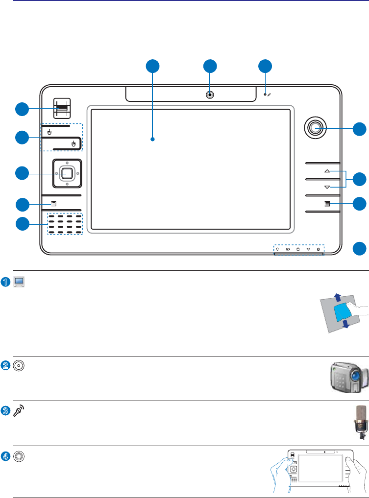
Display Panel
The display panel functions the same as a desktop monitor. The UltraMo-
bilePC uses an active matrix TFT LCD, which provides excellent viewing
like that of desktop monitors. Unlike desktop monitors, the LCD panel
GRHVQRWSURGXFHDQ\UDGLDWLRQRUÁLFNHULQJVRLWLVHDVLHURQWKHH\HV
Use a soft cloth without chemical liquids (use plain water if necessary)
Front Side
Refer to the diagram below to identify the components on this side of the UltraMobilePC.
1 2
6
7
3
4
5
8
10
10
11
12
9
9
2
3
1
Camera
The built-in camera allows picture taking or video recording. Can be used
with video conferencing and other interactive applications.
4
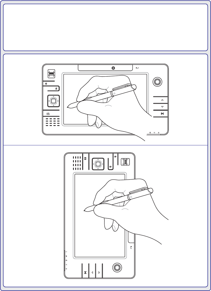
Thumbstick Cursor Control
The thumbstick cursor control with its left and right cursor
buttons is a pointing device that provides the same functions
as a desktop mouse.
1.3M
PIXELS
Microphone (Built-in)
The built-in mono microphone can be used for video conferencing, voice narrations,
or simple audio recordings.
UltraMobilePC
13
Audio Speaker
The built-in speaker system allows you to hear audio without additional
attachments. The multimedia sound system features an integrated digital
audio controller that produces rich, vibrant sound (results improved with
external stereo headphones or speakers). Audio features are software
controlled.
8
9
6
7
5
Microsoft Touch Pack Key
Pressing this button will launch a software built exclusively for UMPCs (Ultra Mobile
Personal Computers) called Microsoft Touch Pack.
10
11
12
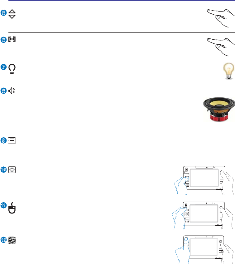
Direction & Enter Buttons
The direction (Up/Down, Left/Right) and Enter (center) but-
tons act the same way as those on a keyboard.
1.3M
PIXELS
Thumbstick Cursor Buttons
The thumbstick cursor control with its left and right cursor
buttons is a pointing device that provides the same functions
as a desktop mouse.
1.3M
PIXELS
UltraMobilePC Settings Button
The UltraMobilePC settings button bring up an easy menu to customize the
UltraMobilePC to your desire.
Page Up & Page Down
The Page Up and Page Down buttons act the same way as those on a key-
board.
Fingerprint Scanner
7KHEXLOWLQÀQJHUSULQWVFDQQHUDOORZVXVHRIVHFXULW\VRIWZDUH
XVLQJ\RXUÀQJHUSULQWDV\RXULGHQWLÀFDWLRQNH\
1.3M
PIXELS
Status Indicators
Status indicators represent various conditions. Details are described in section 3.
14
UltraMobilePC
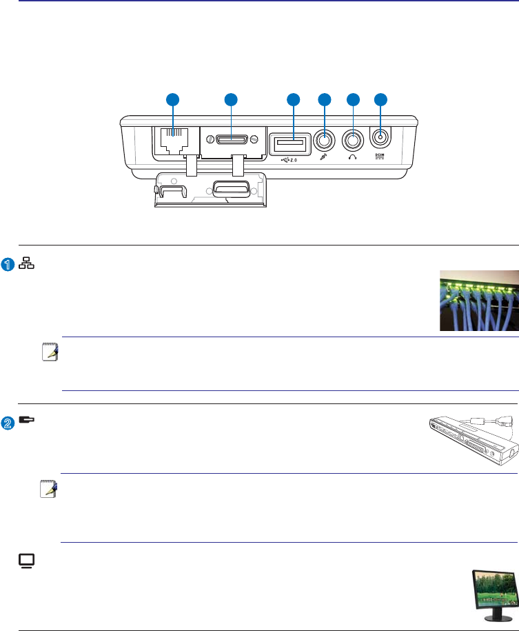
Right Side
Refer to the diagram below to identify the components on this side of the UltraMobilePC.
Expansion Port
The expansion port provides an easy-to-use PortBar docking solution to
desktop peripherals and other accessories through a single connector.
2
1
<-------- combo -------->
Notes: (1) AC power adapter must be used. Cannot be used when UltraMobilePC
is in battery mode. (2) Recommend using two AC power adapters (one on the
UltraMobilePC and one on the PortBar) when using all ports on UltraMobilePC
and PortBar. (3) Disables UltraMobilePC’s LAN port when connected.
Note: An active LAN cable must be connected in order for Windows device man-
ager to detect the built-in LAN. For the same reason, an active LAN cable must
be connected when installing a LAN driver.
1 2 3 4 5 6
LAN Port (disabled when using PortBar)
The RJ-45 LAN port with eight pins is larger than the RJ-11 modem
port and supports a standard Ethernet cable for connection to a local
network. The built-in connector allows convenient use without addi-
tional adapters.
Display (Monitor) Output (with provided adapter)
The provided VGA adapter for the expansion port will provide a 15-pin D-sub
analog output to support a standard VGA-compatible device such as a monitor
or projector to allow displaying on a larger external monitor.
UltraMobilePC
15
3
4
6
5
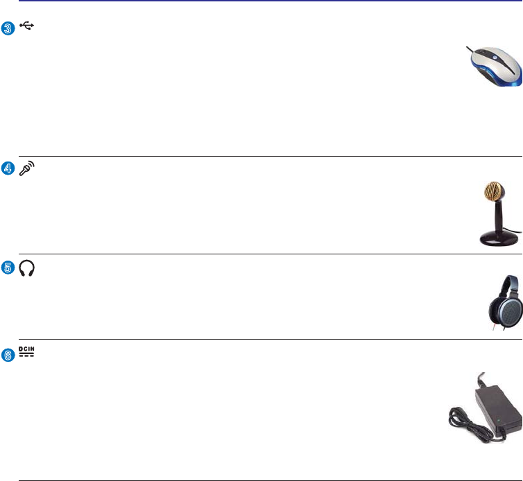
Headphone Output Jack
The stereo headphone jack (1/8 inch) is used to connect the UltraMobilePC’s au-
GLRRXWVLJQDOWRDPSOLÀHGVSHDNHUVRUKHDGSKRQHV8VLQJWKLVMDFNDXWRPDWLFDOO\
disables the built-in speakers.
Microphone Input Jack
The mono microphone jack (1/8 inch) can be used to connect an external mi-
crophone or output signals from audio devices. Using this jack automatically
disables the built-in microphone. Use this feature for video conferencing, voice
narrations, or simple audio recordings.
Power (DC) Input
The supplied power adapter converts AC power to DC power for use
with this jack. Power supplied through this jack supplies power to the
UltraMobilePC and charges the internal battery pack. To prevent damage
to the UltraMobilePC and battery pack, always use the supplied power
adapter. CAUTION: MAY BECOME WARM TO HOT WHEN IN
USE. BE SURE NOT TO COVER THE ADAPTER AND KEEP IT
AWAY FROM YOUR BODY.
2.0
USB Port (2.0/1.1)
The USB (Universal Serial Bus) port is compatible with USB 2.0 or USB
1.1 devices such as keyboards, pointing devices, cameras, hard disk drives,
printers, and scanners connected in a series up to 12Mbits/sec (USB 1.1)
and 480Mbits/sec (USB 2.0). USB allows many devices to run simultaneously
on a single computer, with some peripherals acting as additional plug-in sites or hubs.
USB supports hot-swapping of devices so that most peripherals can be connected or
disconnected without restarting the computer.
16
UltraMobilePC
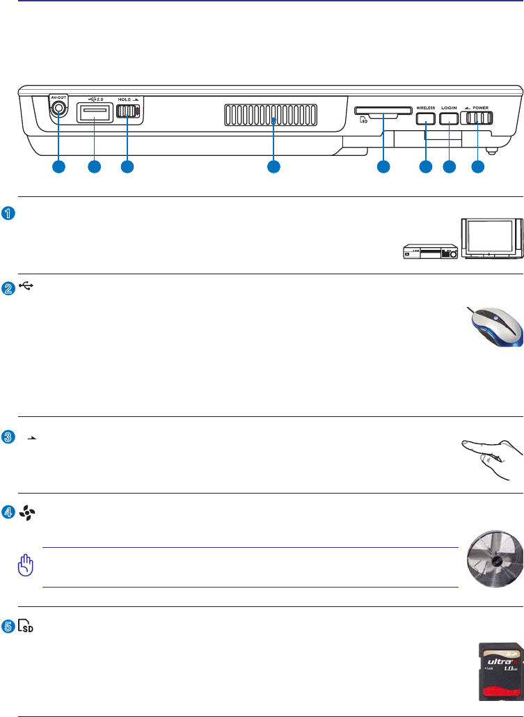
Top Side
Refer to the diagram below to identify the components on this side of the UltraMobilePC.
1 2 3 5 6 7 84
2
3
4
1
5
AV-OUT
Audio/Video output port for connection to analog audio/video
devices such as televisions or video recorders.
AV-O UT
Hold Key
When enabled, the buttons and the touchscreen will be disabled but the
UltraMobilePC will continue to function (such as playing music).
HOLD
SD Memory Slot
This UltraMobilePC has a built-in SD memory card reader that can read SD
ÁDVKPHPRU\FDUGVIURPGHYLFHVVXFKDVGLJLWDOFDPHUDV03SOD\HUVPRELOH
phones, and PDAs. The built-in SD memory card reader is not only convenient,
but also faster than most external SD memory card readers.
Air Vents
The air vents allow cool air to enter and warm air to exit the system.
IMPORTANT! Make sure that paper, books, clothing, cables, or other ob-
jects do not block any of the air vents or else overheating may occur.
2.0
USB Port (2.0/1.1)
The USB (Universal Serial Bus) port is compatible with USB 2.0 or USB
1.1 devices such as keyboards, pointing devices, cameras, hard disk drives,
printers, and scanners connected in a series up to 12Mbits/sec (USB 1.1)
and 480Mbits/sec (USB 2.0). USB allows many devices to run simultaneously
on a single computer, with some peripherals acting as additional plug-in sites or hubs.
USB supports hot-swapping of devices so that most peripherals can be connected or
disconnected without restarting the computer.

UltraMobilePC
17
8
6
7
Power Switch
The power switch turns ON and OFF the UltraMobilePC or putting the Ul-
traMobilePC into sleep or hibernation modes. Actual behavior of the power
switch can be customized in Windows Control Panel “Power Options.”
POWER
LOGIN Button
The LOGIN button sends a [Ctrl][Alt][Del] keyboard combination to the
operating system to show Windows Security for logging in/off, locking,
shutting down, showing task manager, or changing passwords. This special
login feature is also known as Secure Attention Sequence (SAS).
LOGIN
Wireless Switch
Enables or disables the built-in wireless LAN and Bluetooth (selected
models). When enabled, the wireless status indicator will light. Windows
software settings are necessary before use.
WIRELESS
18
UltraMobilePC
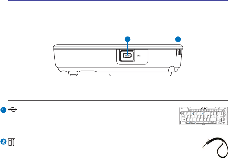
Left Side
Refer to the diagram below to identify the components on this side of the UltraMobilePC.
1 2
2
1
Mini-USB Port (Type A)
The mini-USB (Universal Serial Bus) port is for connection to the
optional external USB keyboard.
PgUp
PgDn
PrtSc
Break
Pause
SysRq
F1 F2 F3 F4 F5 F6 F7F7 F8F8 F9F9
F10F10
F11F1
F1F12
Home
End
LOCK UNLOCK
Wrist strap hook
The wrist strap hook is for use with the wrist strap to prevent accidentally
dropping the UltraMobilePC when holding it in your hands.
UltraMobilePC
19
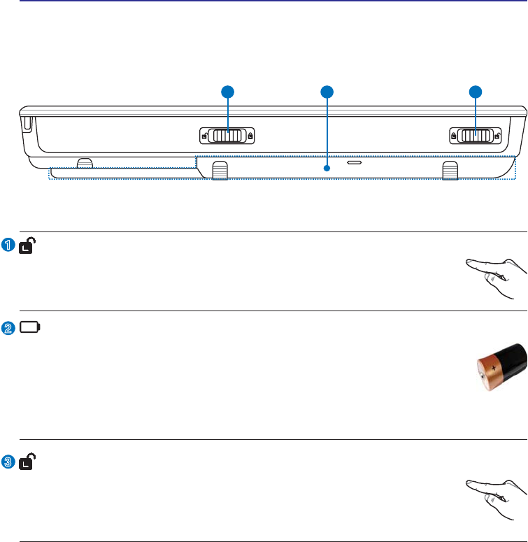
Bottom Side
Refer to the diagram below to identify the components on this side of the UltraMobilePC.
1 32
2
3
1
Battery Lock - Manual
The manual battery lock is used to keep the battery pack secured. Move
the manual lock to the unlocked position to insert or remove the battery
pack. Move the manual lock to the locked position after inserting the bat-
tery pack.
Battery Lock - Spring
The spring battery lock is used to keep the battery pack secured. When the
battery pack is inserted, it will automatically lock. To remove the battery
pack, this spring lock must be held in the unlocked position.
Battery Pack
The battery pack is automatically charged when the UltraMobilePC is con-
nected to an AC power source and maintains power to the UltraMobilePC
when AC power is not connected. This allows use when moving temporarily
EHWZHHQORFDWLRQV%DWWHU\WLPHYDULHVE\XVDJHDQGE\WKHVSHFLÀFDWLRQVIRU
this UltraMobilePC. The battery pack cannot be disassembled and must be purchased
as a single unit from an authorized retailer.
20
UltraMobilePC
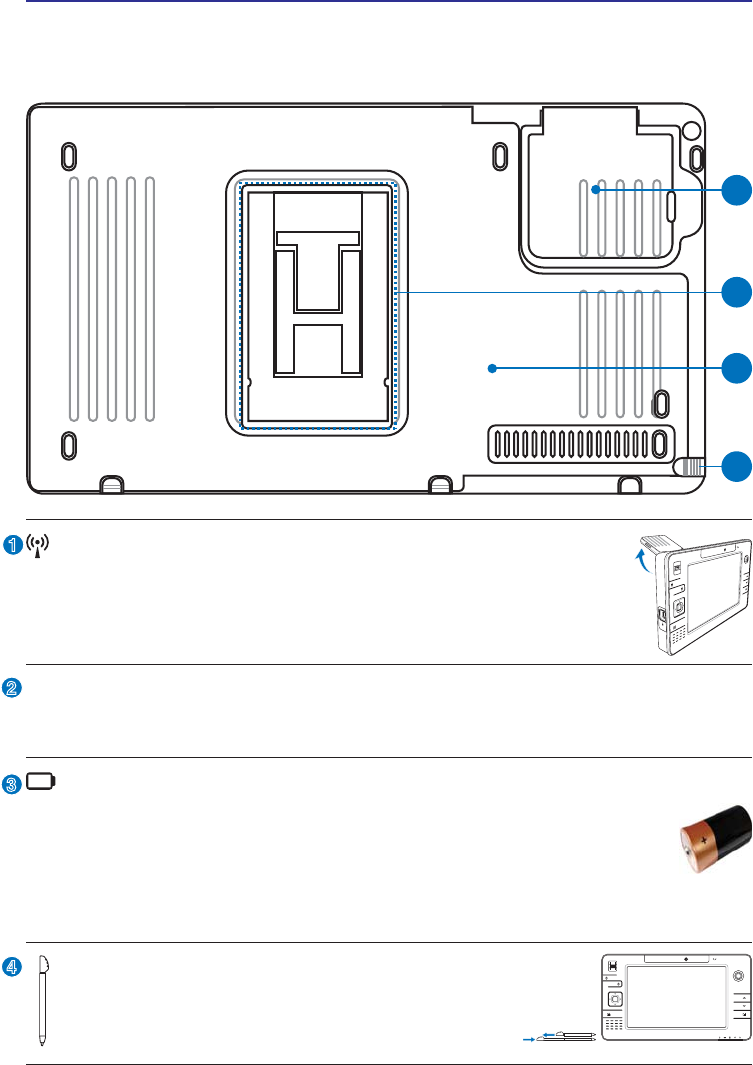
Back Side
Refer to the diagram below to identify the components on this side of the UltraMobilePC.
1
2
4
3
2
3
1
GPS Antenna (built-in)
7KH*36DQWHQQDFDQEHÁLSSHGXSIRUEHWWHUUHFHSWLRQRUÁLSSHGGRZQ
when not in use. The GPS antenna is used by the built-in SiRF3 GPS
chipset. Together, the built-in GPS can be used with various navigation
software applications without additional attachments.
1.3M
PIXELS
Touchscreen Pen Compartment
This compartment allows storage of the pen used on the touchscreen
panel. Note: The touchscreen pen replicates cursor functions on the
touchscreen and does not have electronic components.
1.3M
PIXELS
Battery Pack
The battery pack is automatically charged when the UltraMobilePC is con-
nected to an AC power source and maintains power to the UltraMobilePC
when AC power is not connected. This allows use when moving temporarily
EHWZHHQORFDWLRQV%DWWHU\WLPHYDULHVE\XVDJHDQGE\WKHVSHFLÀFDWLRQVIRU
this UltraMobilePC. The battery pack cannot be disassembled and must be purchased
as a single unit from an authorized retailer.
Support Stand
The battery pack is equipped with a foldable support stand for the UltraMobilePC to
VWDQGXSRQDÁDWVXUIDFHIRUHDV\YLHZLQJ
4
UltraMobilePC
21
1
2
3
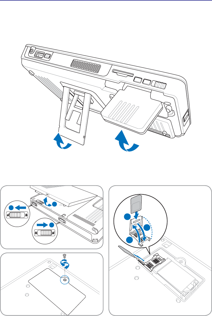
Back Side (cont.)
7KHVXSSRUWVWDQGDQG*36DQWHQQDFDQÁLSRXWDVLOOXVWUDWHGZKHQXVLQJWKHP)OLSWKHP
back in for easy handling or transport.
SIM card location and installation
2
1
2

22
UltraMobilePC

UltraMobilePC
23
3. Getting Started
Using AC Power
Using Battery Power
Powering ON the UltraMobilePC
Checking Battery Power
Restarting or Rebooting
Powering OFF the UltraMobilePC
Status Indicators
NOTE: Photos and icons in this manual are used for artistic purposes only and do
not show what is actually used in the product itself.
24
UltraMobilePC
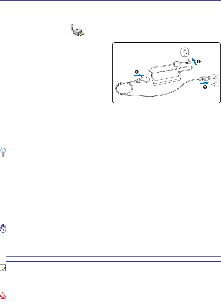
With the AC power cord connected to the AC-DC converter, connect the AC power cord to
an AC outlet (preferably with surge-protection) and then connect the DC plug to the Ultra-
0RELOH3&&RQQHFWLQJWKH$&'&DGDSWHUWRWKH$&RXWOHWÀUVWDOORZV\RXWRWHVWWKH$&
outlet’s power and the AC-DC converter itself for compatibility problems before connecting
the DC power to the UltraMobilePC. The power indicator on the adapter (if available) will
light if the power is within accepted ranges.
Power System
Using AC Power
The UltraMobilePC power is comprised of
two parts, the power adapter and the battery
power system. The power adapter converts
AC power from a wall outlet to the DC power
required by the UltraMobilePC. Your Ultra-
MobilePC comes with a universal AC-DC
adapter. That means that you may connect
the power cord to any 100V-120V as well as
220V-240V outlets without setting switches
or using power converters. Different countries
may require that an adapter be used to connect the provided US-standard AC power cord to
a different standard. Most hotels will provide universal outlets to support different power
cords as well as voltages. It is always best to ask an experienced traveler about AC outlet
voltages when bringing power adapters to another country.
TIP: You can buy travel kits for the UltraMobilePC that includes power and modem
adapters for almost every country.
IMPORTANT! Damage may occur if you use a different adapter to power the UltraMo-
bilePC or use the UltraMobilePC’s adapter to power other electrical devices. If there is
smoke, burning scent, or extreme heat coming from the AC-DC adapter, seek servic-
ing. Seek servicing if you suspect a faulty AC-DC adapter. You may damage both your
battery pack(s) and the UltraMobilePC with a faulty AC-DC adapter.
NOTE: This UltraMobilePC may come with either a two or three-prong plug depending
on territory. If a three-prong plug is provided, you must use a grounded AC outlet or
use a properly grounded adapter to ensure safe operation of the UltraMobilePC.
WARNING! THE POWER ADAPTER MAY BECOME WARM TO HOT WHEN IN USE. BE
SURE NOT TO COVER THE ADAPTER AND KEEP IT AWAY FROM YOUR BODY.
UltraMobilePC
25
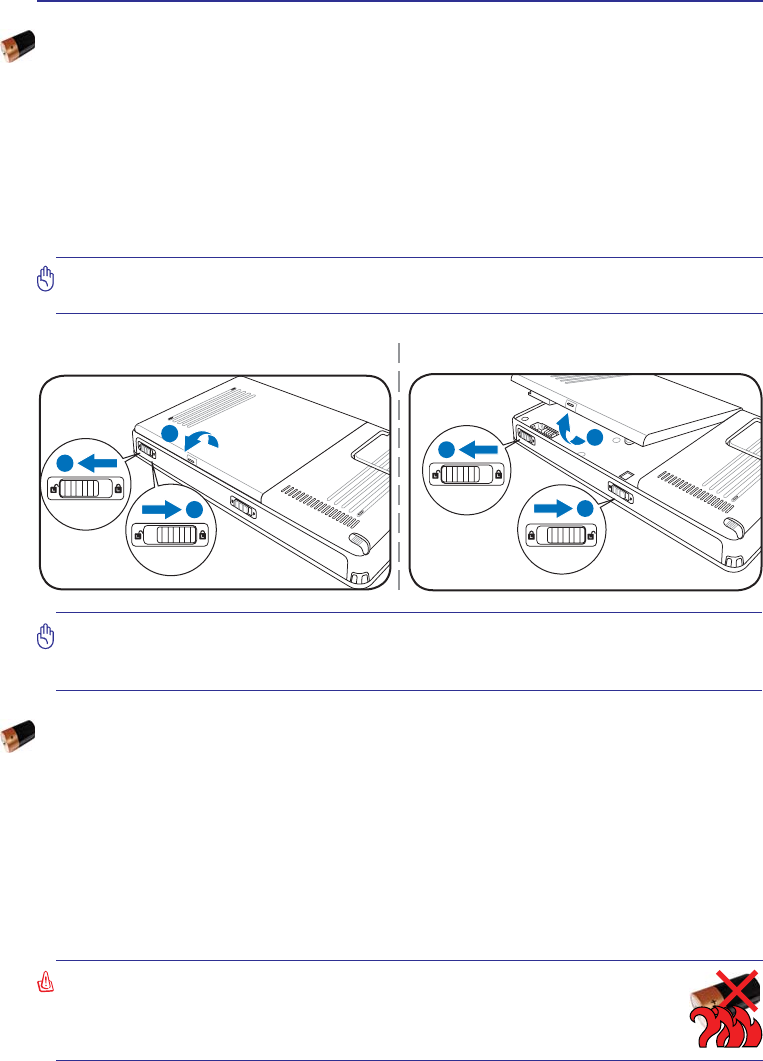
IMPORTANT! Never attempt to remove the battery pack while the UltraMobilePC is
turned ON, as this may result in the loss of working data.
IMPORTANT! Only use battery packs and power adapters supplied with this UltraMo-
ELOH3&RUVSHFLÀFDOO\DSSURYHGE\WKHPDQXIDFWXUHURUUHWDLOHUIRUXVHZLWKWKLVPRGHO
or else damage may occur to the UltraMobilePC.
2
1
3
2
1
2
To install the battery pack: To remove the battery pack:
:$51,1*)RUVDIHW\UHDVRQV'2127WKURZWKHEDWWHU\LQÀUH'2127
short circuit the contacts, and DO NOT disassemble the battery. If there is
any abnormal operation or damage to the battery pack caused by impact,
turn OFF the UltraMobilePC and contact an authorized service center.
Using Battery Power
The UltraMobilePC is designed to work with a removable battery pack. The battery pack consists
of a set of battery cells housed together. A fully charged pack will provide several hours of battery
life, which can be further extended by using power management features through the BIOS setup.
Additional battery packs are optional and can be purchased separately through a retailer.
Installing and Removing the Battery Pack
Your UltraMobilePC may or may not have its battery pack installed. If your UltraMobilePC does
not have its battery pack installed, use the following procedures to install the battery pack.
Battery Care
The UltraMobilePC’s battery pack, like all rechargeable batteries, has a limit on the number times
it can be recharged. The battery pack’s useful life will depend on your environment temperature,
humidity, and how your UltraMobilePC is used. It is ideal that the battery be used in a tem-
SHUDWXUHUDQJHEHWZHHQÝ&DQGÝ&Ý)DQGÝ)<RXPXVWDOVRWDNHLQWRDFFRXQWWKDWWKH
UltraMobilePC’s internal temperature is higher than the outside temperature. Any temperatures
above or below this range will shorten the life of the battery. But in any case, the battery pack’s
usage time will eventually decrease and a new battery pack must be purchased from an authorized
dealer for this UltraMobilePC. Because batteries also have a shelf life, it is not recommended to
buy extras for storing.

26
UltraMobilePC
Powering ON the UltraMobilePC
The UltraMobilePC’s power-ON message appears on the screen when you turn it ON. If
necessary, you may adjust the brightness by using the hotkey. If you need to run the BIOS
6HWXSWRVHWRUPRGLI\WKHV\VWHPFRQÀJXUDWLRQSUHVV>)@XSRQERRWXSWRHQWHUWKH%,26
Setup. If you press [Tab] during the splash screen, standard boot information such as the
BIOS version can be seen. Press [ESC] and you will be presented with a boot menu with
selections to boot from your available drives.
127(%HIRUHERRWXSWKHGLVSOD\SDQHOÁDVKHVZKHQWKHSRZHULVWXUQHG217KLV
is part of the UltraMobilePC’s test routine and is not a problem with the display.
IMPORTANT! To protect the hard disk drive, always wait at least 5 seconds after
turning OFF your UltraMobilePC before turning it back ON.
WARNING! DO NOT carry or cover a UltraMobilePC that is powered ON with any
materials that will reduce air circulation such as a carrying bag.
The Power-On Self Test (POST)
:KHQ\RXWXUQ21WKH8OWUD0RELOH3&LWZLOOÀUVWUXQWKURXJKDVHULHVRIVRIWZDUHFRQWUROOHG
diagnostic tests called the Power-On Self Test (POST). The software that controls the POST
is installed as a permanent part of the UltraMobilePC’s architecture. The POST includes a
UHFRUGRIWKH8OWUD0RELOH3&·VKDUGZDUHFRQÀJXUDWLRQZKLFKLVXVHGWRPDNHDGLDJQRVWLF
check of the system. This record is created by using the BIOS Setup program. If the POST
discovers a difference between the record and the existing hardware, it will display a mes-
VDJHRQWKHVFUHHQSURPSWLQJ\RXWRFRUUHFWWKHFRQÁLFWE\UXQQLQJ%,266HWXS,QPRVW
cases the record should be correct when you receive the UltraMobilePC. When the test is
ÀQLVKHG\RXPD\JHWDPHVVDJHUHSRUWLQJ´1RRSHUDWLQJV\VWHPIRXQGµLIWKHKDUGGLVNZDV
not preloaded with an operating system. This indicates that the hard disk is correctly detected
and ready for the installation of a new operating system.
The S.M.A.R.T. (Self Monitoring and Reporting Technology) checks the hard disk drive
during POST and gives a warning message if the hard disk drive requires servicing. If any
critical hard disk drive warning is given during bootup, backup your data immediately and
run Windows disk checking program. To run Window’s disk checking program: (1) right-
click any hard disk drive icon in “My Computer”, (2) choose Properties, (3) click the Tools
tab, (4) click Check Now, (5) select a hard disk drive, (6) select Thorough to also check for
physical damages, and (7) click Start. Third party disk utilities such as Symantec’s Norton
Disk Doctor can also perform the same functions but with greater ease and more features.
IMPORTANT! If warnings are still given during bootup after running a software disk
checking utility, you should take your UltraMobilePC in for servicing. Continued use
may result in data loss.
UltraMobilePC
27
NOTE: You will be warned when battery power is low. If you continue to ignore the
low battery warnings, the UltraMobilePC eventually enters suspend mode (Windows
default uses STR).
WARNING! Suspend-to-RAM (STR) does not last long when the battery power is
depleted. Suspend-to-Disk (STD) is not the same as power OFF. STD requires a small
amount of power and will fail if no power is available due to complete battery deple-
tion or no power supply (e.g. removing both the power adapter and battery pack).
1RWH6FUHHQFDSWXUHVVKRZQKHUHDUHH[DPSOHVRQO\DQGPD\QRWUHÁHFW
what you see in your system.
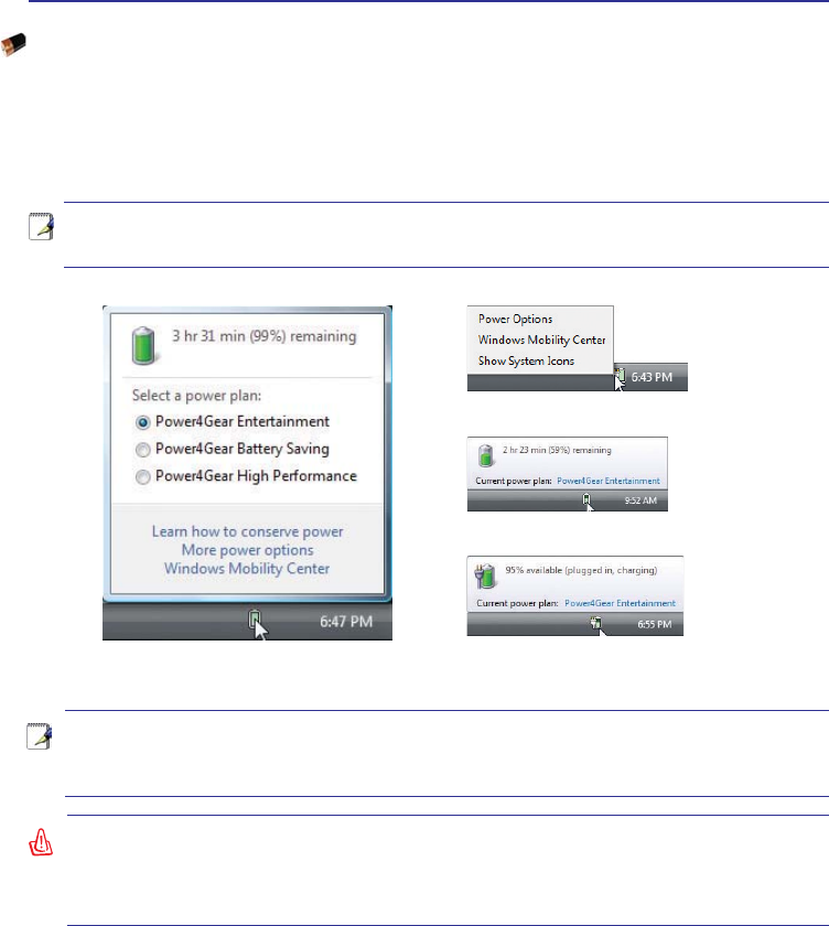
Checking Battery Power
The battery system implements the Smart Battery standard under the Windows environment,
which allows the battery to accurately report the amount of charge left in the battery. A fully-
charged battery pack provides the UltraMobilePC a few hours of working power. But the
DFWXDOÀJXUHYDULHVGHSHQGLQJRQKRZ\RXXVHWKHSRZHUVDYLQJIHDWXUHV\RXUJHQHUDOZRUN
habits, the CPU, system memory size, and the size of the display panel.
Left-click the battery icon
Cursor over the battery icon without
power adapter.
Cursor over the battery icon with
power adapter.
Right-click the battery icon
28
UltraMobilePC
IMPORTANT! To protect the hard drive, wait at least 5 seconds after turning OFF
your UltraMobilePC before turning it back ON.
IMPORTANT! Do not use emergency shutdown while data is being written; doing
so can result in loss or destruction of your data.
WARNING! Do not leave the battery pack discharged. The battery pack will discharge
over time. If not using a battery pack, it must continued to be charged every three
months to extend recovery capacity or else it may fail to charge in the future.
NOTE: The battery stops charging if the temperature is too high or the battery voltage
is too high. BIOS provides a smart battery refreshing function. If the battery calibra-
tion process fails, stop charging and contact an authorized service center.
Charging the Battery Pack
Before you use your UltraMobilePC on the road, you will have to charge the battery pack.
The battery pack begins to charge as soon as the UltraMobilePC is connected to external
SRZHUXVLQJWKHSRZHUDGDSWHU)XOO\FKDUJHWKHEDWWHU\SDFNEHIRUHXVLQJLWIRUWKHÀUVWWLPH
A new battery pack must completely charge before the UltraMobilePC is disconnected from
external power. It takes a few hours to fully charge the battery when the UltraMobilePC is
turned OFF and may take twice the time when the UltraMobilePC is turned ON. The battery
status indicator on the UltraMobilePC turns OFF when the battery pack is charged.
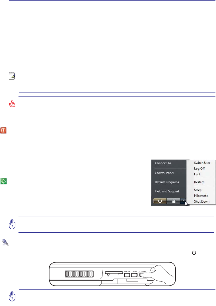
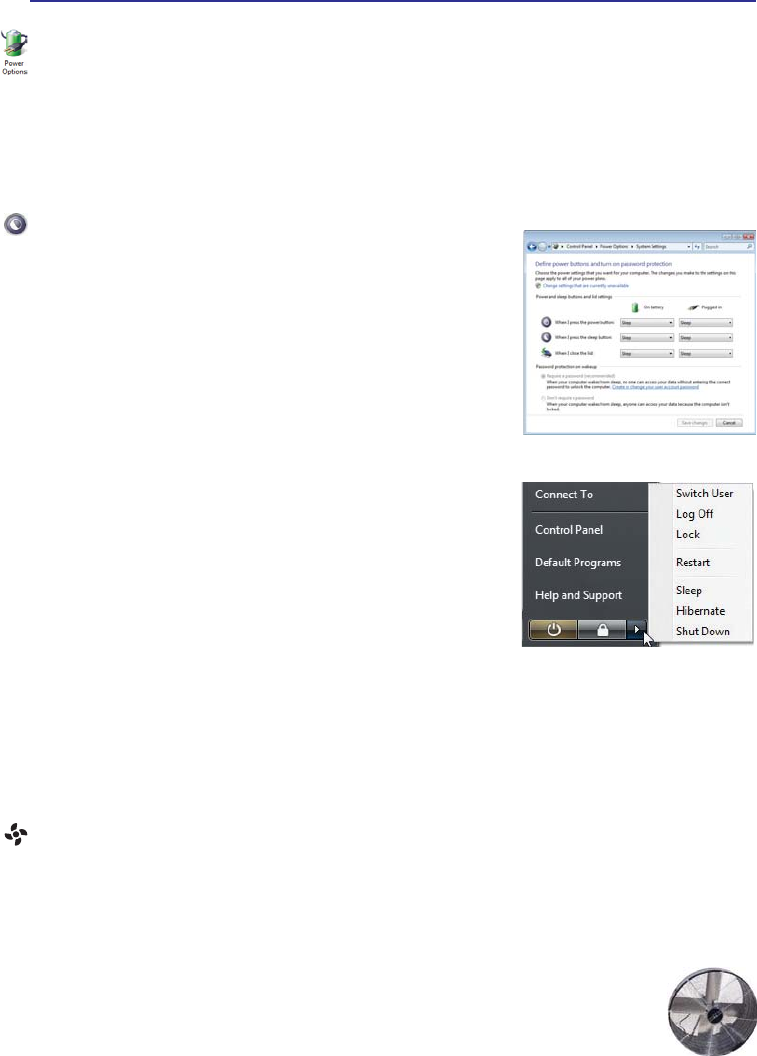
Power Options
The power switch turns ON and OFF the UltraMobilePC or putting the UltraMobilePC
into sleep or hibernation modes. Actual behavior of the power switch can be customized in
Windows Control Panel “Power Options.”
For other options, such as “Switch User, Restart, Sleep, or Shut
Down,” click the arrowhead next to the lock icon.
Restarting or Rebooting
After making changes to your operating system, you may be
prompted to restart the system. Some installation processes
will provide a dialog box to allow restart. To restart the system
manually, choose Restart.
Emergency Shutdown
In case your system cannot properly turn OFF or restart, hold the power button over 4
seconds.
UltraMobilePC
29
Power Management Modes
The UltraMobilePC has a number of automatic or adjustable power saving features that you can
use to maximize battery life and lower Total Cost of Ownership (TCO). You can control some
of these features through the Power menu in the BIOS Setup. ACPI power management settings
are made through the operating system. The power management features are designed to save as
much electricity as possible by putting components into a low power consumption mode as often
as possible but also allow full operation on demand.
Sleep and Hibernate
Power management settings can be found in the Windows >
Control Panel > Power Options. In System Settings, you can
GHÀQH´6OHHS+LEHUQDWHµRU´6KXW'RZQµIRUFORVLQJWKHGLVSOD\
SDQHO RU SUHVVLQJ WKH SRZHU EXWWRQ ´6OHHSµ DQG ´+LEHUQDWHµ
saves power when your UltraMobilePC is not in use by turning
OFF certain components. When you resume your work, your
last status (such as a document scrolled down half way or email
typed half way) will reappear as if you never left. “Shut Down”
will close all applications and ask if you want to save your work
if any are not saved.
Sleep is the same as Suspend-to-RAM (STR). This function stores
your current data and status in RAM while many components are
turned OFF. Because RAM is volatile, it requires power to keep
(refresh) the data. Click the Start button and the arrowhead next
to the lock icon to see this option. (NOTE: The power indicator
will blink in this mode.)
Hibernate is the same as Suspend-to-Disk (STD) and stores your current data and status on the
hard disk drive. By doing this, RAM does not have to be periodically refreshed and power con-
sumption is greatly reduced but not completely eliminated because certain wake-up components
OLNH/$1QHHGVWRUHPDLQSRZHUHG´+LEHUQDWHµVDYHVPRUHSRZHUFRPSDUHGWR´6OHHSµ&OLFN
the Start button and the arrowhead next to the lock icon to see this option. Recover by pressing
the power button. (NOTE: The power indicator will be OFF in this mode.)
Thermal Power Control
There are three power control methods for controlling the UltraMobilePC’s thermal state. These pow-
HUFRQWUROFDQQRWEHFRQÀJXUHGE\WKHXVHUDQGVKRXOGEHNQRZQLQFDVHWKH8OWUD0RELOH3&VKRXOG
enter these states. The following temperatures represent the chassis temperature (not CPU).
• The fan turns ON for active cooling when the temperature reaches the safe upper limit.
• The CPU decreases speed for passive cooling when the temperature exceeds the
safe upper limit.
• The system shut down for critical cooling when temperature exceeds the maximum
safe upper limit.
30
UltraMobilePC
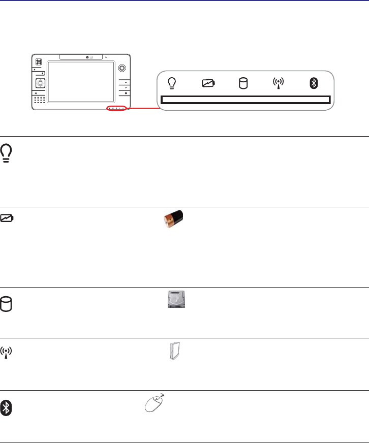
Status Indicators
Power Indicator
The power indicator lights when the UltraMobilePC is turned ON and blinks slowly
when the UltraMobilePC is in the Suspend-to-RAM (Standby) mode. This indicator is
2))ZKHQWKH8OWUD0RELOH3&LVWXUQHG2))RULQWKH6XVSHQGWR'LVN+LEHUQDWLRQ
mode.
Battery Charge Indicator
The battery charge indicator shows the status of the battery’s power as follows:
ON: The UltraMobilePC’s battery is charging when AC power is connected.
OFF: The UltraMobilePC’s battery is charged or completely drained.
Blinking: Battery power is less than 10% and the AC power is not connected.
Drive Activity Indicator
Indicates that the UltraMobilePC is accessing one or more storage device(s) such as the
KDUGGLVN7KHOLJKWÁDVKHVSURSRUWLRQDOWRWKHDFFHVVWLPH
Wireless LAN Indicator
When the built-in wireless LAN is enabled, this indicator will light. (Windows software
settings are necessary to use this function.)
Bluetooth Indicator
This is only applicable on models with internal Bluetooth. This indicator will light to
show that the UltraMobilePC’s built-in Bluetooth function is activated.

UltraMobilePC
31
4. Using the UltraMobilePC
Display Calibration
Connections
Network Connection
Wireless LAN Connection
Bluetooth Wireless Connection
Power Management Modes
Fingerprint Scanner
GPS Software
NOTE: Photos and icons in this manual are used for artistic purposes only and do not
show what is actually used in the product itself.
32
UltraMobilePC
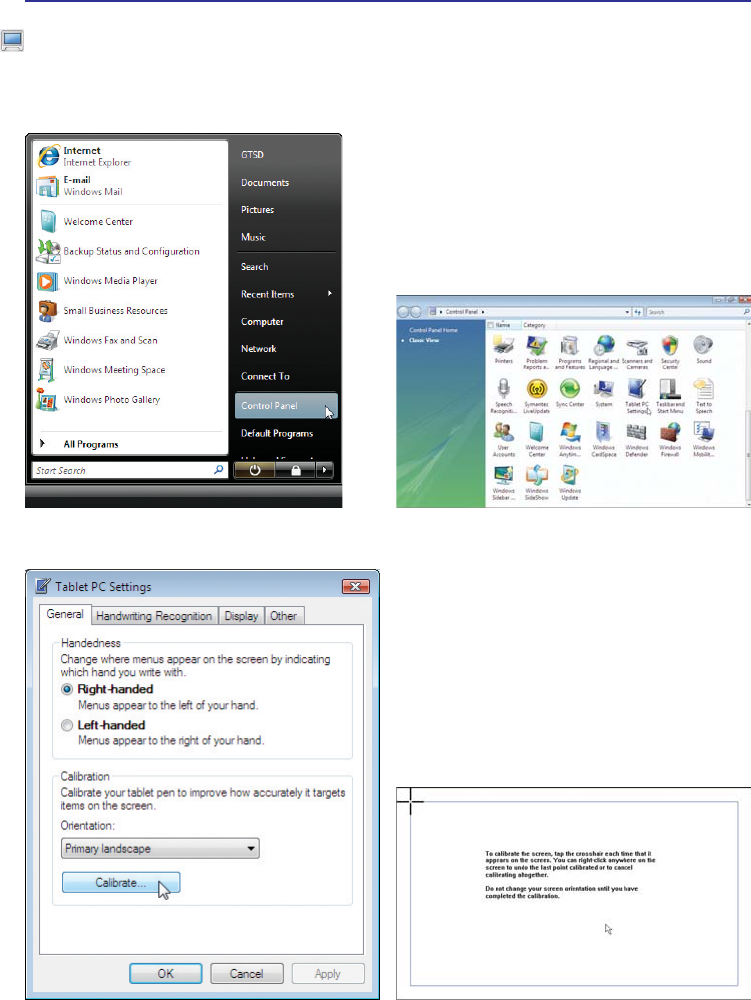
Display Calibration
MS Windows Vista
1. Launch Control Panel from Windows
Start.
3. Click the Calibrate button on the “General”
page.
2. Double click Tablet PC Settings icon.
4. Carefully tap the center of each cross hair
that appears near each corner to complete
the calibration process.
UltraMobilePC
33
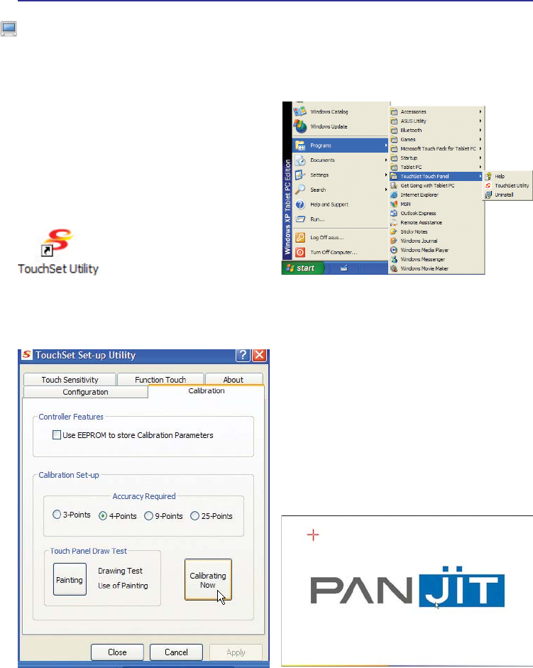
1. Double click the TouchSet Utility icon on
the desktop.
3. Click the Calibration tab and click the Cali-
brating Now button.
2. Or launch TouchSet Utility through Win-
dows Start.
4. Carefully tap the center of each cross hair
that appears near each corner to complete
the calibration process.
Display Calibration (cont.)
MS Windows XP
34
UltraMobilePC
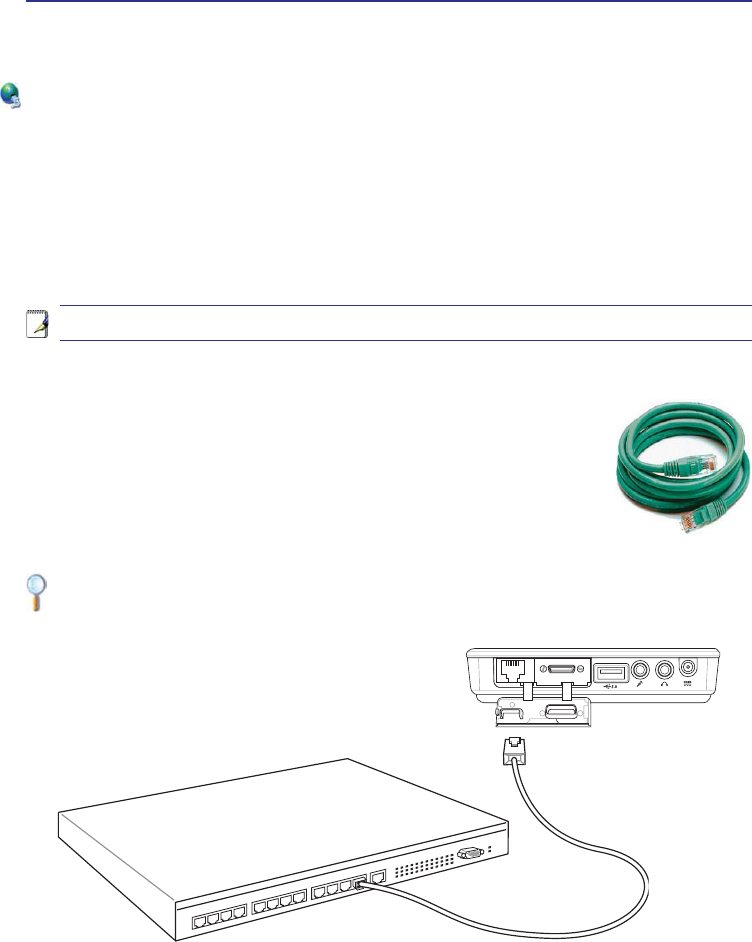
Network Hub or
Switch
Network cable with RJ-45
connectors
Example of the UltraMobilePC connected to a Network Hub or Switch for use with the
built-in Ethernet controller.
Network Connection
Connect a network cable, with RJ-45 connectors on each end, to the modem/network port on the
UltraMobilePC and the other end to a hub or switch. For 100 BASE-TX / 1000 BASE-T speeds,
your network cable must be category 5 or better (not category 3) with twisted-pair wiring. If you
plan on running the interface at 100/1000Mbps, it must be connected to a 100 BASE-TX / 1000
BASE-T hub (not a BASE-T4 hub). For 10Base-T, use category 3, 4, or 5 twisted-pair wiring.
10/100 Mbps Full-Duplex is supported on this UltraMobilePC but requires connection to a net-
work switching hub with “duplex” enabled. The software default is to use the fastest setting so no
user-intervention is required.
Twisted-Pair Cable
7KHFDEOHXVHGWRFRQQHFWWKH(WKHUQHWFDUGWRDKRVWJHQHUDOO\D+XERU6ZLWFK
is called a straight-through Twisted Pair Ethernet (TPE). The end connectors
are called RJ-45 connectors, which are not compatible with RJ-11 telephone
connectors. If connecting two computers together without a hub in between,
a crossover LAN cable is required (Fast-Ethernet model). (Gigabit models
support auto-crossover so a crossover LAN cable is optional.)
1000BASE-T (or Gigabit) is only supported on selected models.
Connections
UltraMobilePC
35
Wireless LAN Connection (on selected models)
The optional built-in wireless LAN is a compact easy-to-use wireless Ethernet adapter. Implement-
ing the IEEE 802.11 standard for wireless LAN (WLAN), the optional built-in wireless LAN is
capable of fast data transmission rates using Direct Sequence Spread Spectrum (DSSS) and Or-
thogonal Frequency Division Multiplexing (OFDM) technologies on 2.4GHz/5GHz frequencies.
The optional built-in wireless LAN is backward compatible with the earlier IEEE 802.11 standards
allowing seamless interfacing of wireless LAN standards.
The optional built-in wireless LAN is a client adapter that supports Infrastructure and Ad-hoc modes
JLYLQJ\RXÁH[LELOLW\RQ\RXUH[LVWLQJRUIXWXUHZLUHOHVVQHWZRUNFRQÀJXUDWLRQVIRUGLVWDQFHVXS
to 40 meters between the client and the access point.
7RSURYLGHHIÀFLHQWVHFXULW\WR\RXUZLUHOHVVFRPPXQLFDWLRQWKHRSWLRQDOEXLOWLQZLUHOHVV/$1
comes with a 64-bit/128-bit Wired Equivalent Privacy (WEP) encryption and Wi-Fi Protected
Access (WPA) features.
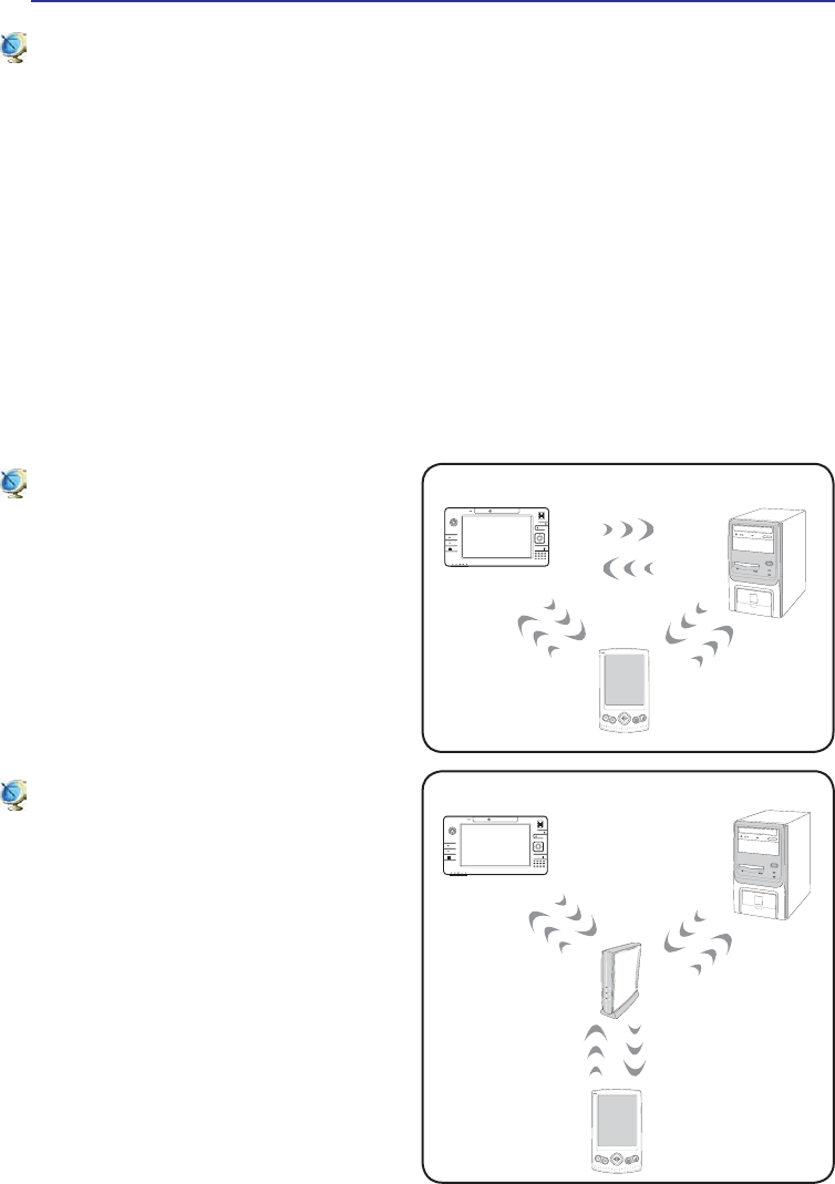
Ad-hoc mode
The Ad-hoc mode allows the UltraMobilePC
to connect to another wireless device. No
access point (AP) is required in this wireless
environment.
(All devices must install optional 802.11 wire-
less LAN adapters.)
Infrastructure mode
The Infrastructure mode allows the UltraMo-
bilePC and other wireless devices to join a
wireless network created by an Access Point
(AP) (sold separately) that provides a central
link for wireless clients to communicate with
each other or with a wired network.
(All devices must install optional 802.11 wire-
less LAN adapters.)
PDA
Access
Point
Desktop PCUltraMobilePC
Desktop PC
PDA
UltraMobilePC
These are examples of the UltraMobilePC connected to
a Wireless Network.