ASUSTeK Computer R50AWI22 ULTRA MOBILE PC User Manual USERS MANUAL 1
ASUSTeK Computer Inc ULTRA MOBILE PC USERS MANUAL 1
UserManual.wiki
>
ASUSTeK Computer
>
R50AWI22 User Manual
>
USERS MANUAL 1
Contents
1.
USERS MANUAL 1
2.
USERS MANUAL 2
USERS MANUAL 1
Navigation menu
Upload a User Manual
Namespaces
Wiki Guide
HTML
PDF
Info
Views
User Manual
Discussion / Help
Navigation
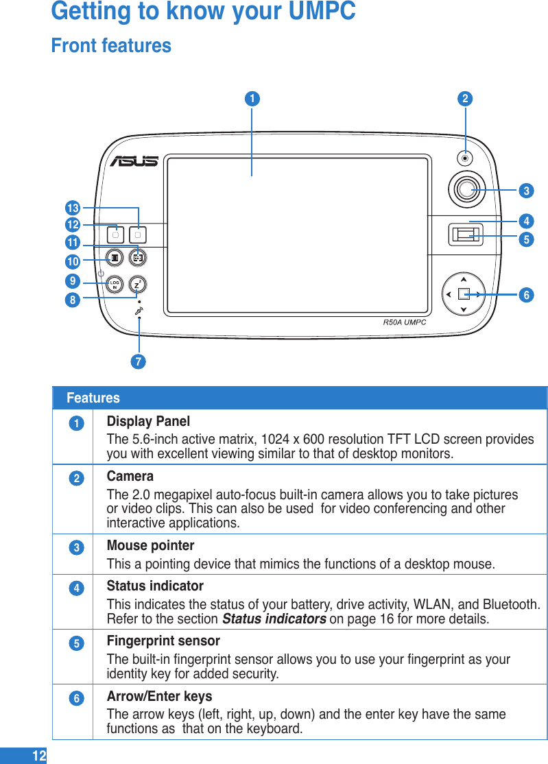
![1313Features7Microphone (Built-in)The built-in mono microphone is used for video conferencing, voice narrations, or simple audio recordings.8Sleep/Standby Mode keyPress this key to put your UMPC into Sleep/Standby mode. Slide down the power switch to awaken your UMPC from its Sleep/Standby mode.9LOGIN keyThe LOGIN button sends a [Ctrl][Alt][Del] keyboard combination to the operating system to show Windows Security for logging in/off, locking, shutting down, showing task manager, or changing passwords. This special login feature is also known as Secure Attention Sequence (SAS).10 UMPC Settings keyThis allows you to set the brightness, volume, resolution or power mode of your UMPC.11 Windows® Media Center keyThis launches the Windows® Media Center which allows you to view and play media les such as video clips, music les, or movies.12 Left keyThis key mimics the left-click action of a desktop mouse.13 Right keyThis key mimics the right-click action of a desktop mouse.](https://usermanual.wiki/ASUSTeK-Computer/R50AWI22.USERS-MANUAL-1/User-Guide-975078-Page-32.png)