ASUSTeK Computer R50AWI22 ULTRA MOBILE PC User Manual USERS MANUAL 1
ASUSTeK Computer Inc ULTRA MOBILE PC USERS MANUAL 1
Contents
- 1. USERS MANUAL 1
- 2. USERS MANUAL 2
USERS MANUAL 1
Wi2Wi, Inc.Doc No. AST-PDT-DOC Rev.1.1
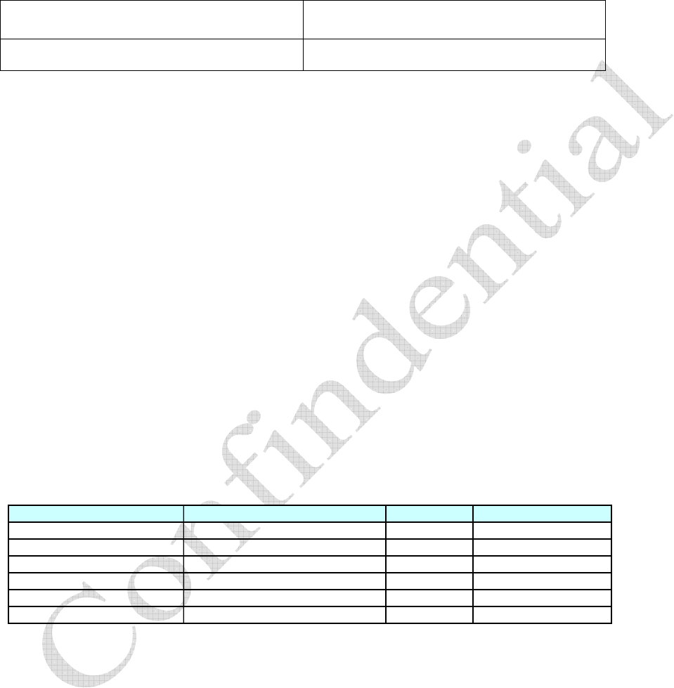
Data Sheet, WLAN-Bluetooth SiP– W2CBW003
Dated: October 20, 2006
The content of this document is to be treated as strictly confidential and is not to be disclosed,
reproduced or used, except as authorized in writing by Wi2Wi, Inc.
Copyright © 2006 Wi2Wi, Inc.
Page 1 of 19
WLAN-Bluetooth SiP
W2CBW003
AST-PDT-DOC Revision 1.1
October 20, 2006

Wi2Wi, Inc.Doc No. AST-PDT-DOC Rev.1.1
Data Sheet, WLAN-Bluetooth SiP– W2CBW003
Dated: October 20, 2006
The content of this document is to be treated as strictly confidential and is not to be disclosed,
reproduced or used, except as authorized in writing by Wi2Wi, Inc.
Copyright © 2006 Wi2Wi, Inc.
Page 2 of 19
Table of Contents
Table of Contents........................................................................................................................2
1 Revision History..................................................................................................................3
2 Scope ...................................................................................................................................4
3 General Features..................................................................................................................4
4 System Description..............................................................................................................5
4.1 Block Diagram.....................................................................................................................5
4.2 Pin Description ....................................................................................................................6
4.3 Pin Map (Top View)............................................................................................................7
5 Electrical Characteristics.....................................................................................................8
6 Coexistence Test Results...................................................................................................10
7 WLAN External Interfaces................................................................................................12
7.1 SDIO Interface...................................................................................................................12
7.2 G-SPI Interface..................................................................................................................12
8 Bluetooth External Interfaces............................................................................................13
8.1 UART Interface.................................................................................................................13
8.2 USB Interface ....................................................................................................................14
8.3 PCM Interface....................................................................................................................14
8.4 SPI Interface ......................................................................................................................15
9 Antenna and Clock ............................................................................................................15
10 Software Specifications.....................................................................................................15
10.1 Wireless LAN....................................................................................................................15
10.2 Bluetooth ...........................................................................................................................16
11 Manufacturing Notes.........................................................................................................17
11.1 Physical Dimensions and Pin Locations............................................................................17
11.2 Recommended Reflow Profile...........................................................................................18
12 Certifications .....................................................................................................................18
13 References .........................................................................................................................19
13.1 Specifications.....................................................................................................................19
13.2 Trademarks, Patents and Licenses.....................................................................................19
13.3 Other..................................................................................................................................19
List of Figures:
Figure 1: Block Diagram ............................................................................................................5
Figure 2: UART Break Signal ..................................................................................................14
Figure 3: Physical Dimensions and Pin Locations ...................................................................17
Figure 4: Recommended Reflow Profile ..................................................................................18
List of Tables:
Table 1: Pin Description .............................................................................................................6
Table 2: Electrical Characteristics ..............................................................................................8
Table 3: SDIO Pin Map ............................................................................................................12
Table 4: UART Baud Rates......................................................................................................13

Wi2Wi, Inc.Doc No. AST-PDT-DOC Rev.1.1
Data Sheet, WLAN-Bluetooth SiP– W2CBW003
Dated: October 20, 2006
The content of this document is to be treated as strictly confidential and is not to be disclosed,
reproduced or used, except as authorized in writing by Wi2Wi, Inc.
Copyright © 2006 Wi2Wi, Inc.
Page 3 of 19
1 Revision History
Document Type: Product Specification
Document Control Number AST-PDT-DOC
Revision 1.1
Date October 20, 2006
Initiator Kathleen Ciampossin
Change History
Revision Revision Date Originator Changes
1.0 9/29/2006 Kathleen Ciampossin First release
1.1 10/20/2006 Dhiraj Sogani First official release; Added the
missing content and changed
formatting.

Wi2Wi, Inc.Doc No. AST-PDT-DOC Rev.1.1
Data Sheet, WLAN-Bluetooth SiP– W2CBW003
Dated: October 20, 2006
The content of this document is to be treated as strictly confidential and is not to be disclosed,
reproduced or used, except as authorized in writing by Wi2Wi, Inc.
Copyright © 2006 Wi2Wi, Inc.
Page 4 of 19
2 Scope
This specification provides a general guideline on the performance and the integration of Wi2Wi’s
802.11b/g + Bluetooth System in Package (SiP) Solution. The SiP, P/N W2CBW003, is targeted to
assist companies to easily integrate both WLAN and Bluetooth functionally into their products. This is
accomplished by reducing their development times and cost by using a complete, small form factor, low
power, ready to integrate Radio System Solution.
The specification maximum and minimum limits presented herein are those guaranteed when the unit is
integrated into the Wi2Wi’s W2CBW003-DEV Development System. These limits are to serve as the
representative performance characteristics of the W2CBW003 when properly designed into a customer’s
product. Wi2Wi makes no warranty, implied or otherwise specified, with respect to a customers design
and the performance characteristics presented in this specification.
The latest revision of this document supersedes all previous versions of this document. Wi2Wi reserves
the right to change this specification without notice.
3 General Features
xCompact design for easy integration: 12mm x 12mm x 1.4mm
xSystem-in-Package LGA with 100 pins
xWLAN technology based on Marvell’s 88W8686
xBluetooth technology based on CSR BC04-ROM
xCertified dual mode radio
xOptimized RF and electrical design for better performance in co-existence with other wireless
standards
xDual-antenna design with separate antennae for Bluetooth and WLAN
xOperates in 2.4GHz ISM band
xROHS Compliant
xSingle supply of 3.3V
xFully integrated coexistence solution
xWLAN Specific Features
oSDIO 1.1 and G-SPI interfaces
oProgrammable GPIOs for applications
o50-Ohm antenna launch
oSupport for WinCE and Linux (can be ported to other operating systems)
o1, 2, 5.5 and 11 Mbps data rates for 802.11b (DSSS/CCK modulation)
o6, 9, 12, 18, 24, 36, 48 and 54 Mpbs data rates for 802.11g (OFDM modulation)
xBluetooth Specific Features
oUART, USB, PCM audio interfaces
oSPI interface for integration, test and diagnostics

Wi2Wi, Inc.Doc No. AST-PDT-DOC Rev.1.1
Data Sheet, WLAN-Bluetooth SiP– W2CBW003
Dated: October 20, 2006
The content of this document is to be treated as strictly confidential and is not to be disclosed,
reproduced or used, except as authorized in writing by Wi2Wi, Inc.
Copyright © 2006 Wi2Wi, Inc.
Page 5 of 19
oProgrammable GPIOs for applications
o50-Ohm antenna launch
oSupport for WinCE and Linux (can be ported to other operating systems)
oGFSK modulation for Bluetooth version 2.0
oS/4 DQPSK, 8DPSK modulation for Bluetooth EDR
oData rate upto 1Mbps for Bluetooth version 2.0
oData rate upto 3 Mbps for Bluetooth EDR
4System Description
W2CBW003 is a complete system-in-package combination of 88W8686 802.11b/g and CSR Bluetooth
BC04 ROM. It includes all the components to operate both the radio. It preserves the characteristics
from individual Marvell and CSR chipsets while providing the optimized the system level functionality
and performance.
4.1 Block Diagram
Figure #1 shows the detailed block diagram of W2CBW003 along with the interfaces.
Figure 1: Block Diagram
BT_RESET
2.4GHz
ANTENNA
2.4G TX
2.4G
BALUN
SPDT
SWITCH
BLUETOOTH
WLAN (802.11 b/g)
3.3V to 1.8V
REG
UART 2.4G
BALUN
BPF
SIP
2.4GHz
ANTENNA
USB
AUDIO
RESETn
EEPROM
PA
MCU_WAKEUPn
EEPROM
2.4G RX
26MHz
CXO
SDIO
88W8686 2.4G
BPF
BC04-ROM

Wi2Wi, Inc.Doc No. AST-PDT-DOC Rev.1.1
Data Sheet, WLAN-Bluetooth SiP– W2CBW003
Dated: October 20, 2006
The content of this document is to be treated as strictly confidential and is not to be disclosed,
reproduced or used, except as authorized in writing by Wi2Wi, Inc.
Copyright © 2006 Wi2Wi, Inc.
Page 6 of 19
4.2 Pin Description
Table 1: Pin Description
Pin Number Pin Name Type Description
WLAN Pins
E2 WF_RESETn I/O WLAN Reset (active low)
K9 WF_ANT RF WLAN RF port to Antenna
H3 WF_SDIO_CMD I/O Standard SDIO command line
F1 WF_SDIO_DATA_3 I/O Standard SDIO data bus
J4 WF_SDIO_CLK I/O Standard SDIO clock line
F4 WF_SDIO_DATA_1 I/O Standard SDIO data bus
K6 WF_SDIO_DATA_2 I/O Standard SDIO data bus
J5 WF_SDIO_DATA_0 I/O Standard SDIO data bus
J2 WF_TDO O
JTAG Test Data Input, external 5GHz LNA
output, reset configuration of XOSC
K7 WF_TR_N O
Transmit Switch Control Negative Output, reset
configuration of internal/external 1.2V regulator
K4 WF_ANT_SEL_N O
Differential antenna select negative output, reset
configuration of host interface select
J3 WF_ANT_SEL_P O Differential antenna select positive output
K3 WF_PA_PE_G O
PA Power Enable Control (802.11g mode), reset
configuration of host interface select
G2 WF_GPIO0 I/O External oscillator control/SLEEPn
H2 WF_GPIO1 I/O Transmit power or receive ready LED
F3 WF_GPIO2 I/O
UART RTS output, reset configuration of
JTAG/function mode
G1 WF_GPIO3 I/O UART DSR input
G4 WF_GPIO4 I/O WLAN MAC wake-up input/interrupt input
D1 WF_GPIO5 I/O UART DTR output, reset configuration of XOSC
E1 WF_GPIO6 I/O
UART SOUT output, reset configuration of
XOSC
A3 CLK_SOURCE I External CLK source if no internal OSC in SIP
F2 WF_SLEEP CLK I
External Sleep clock source if not use internal
sleep clock
G3 WF_PDn I
Full power down, connect to power down pin of
host or 1.8V
Power Pins
C1, C3, G6, F7, A8, B8, G8,
H8, J8, K8, B9, G9, J9, A10,
B10, J10, K10 GND Ground Ground
A1, B1, C2, D2, D3, E3, F5,
J6, G7, H7, J7, F8, H9, G10 3V3_W Power 3.3V Power supply for WLAN
B4, F6, E7, E8, E9, C10,
D10, E10 3V3_B Power 3.3V Power supply for Bluetooth

Wi2Wi, Inc.Doc No. AST-PDT-DOC Rev.1.1
Data Sheet, WLAN-Bluetooth SiP– W2CBW003
Dated: October 20, 2006
The content of this document is to be treated as strictly confidential and is not to be disclosed,
reproduced or used, except as authorized in writing by Wi2Wi, Inc.
Copyright © 2006 Wi2Wi, Inc.
Page 7 of 19
Pin Number Pin Name Type Description
Bluetooth Pins
A9 BT_ANT RF Bluetooth RF port for antenna
C5 BT_PCM_CLK I/O Synchronous data clock
C4 BT_PCM_IN I Synchronous data input
C8 BT_PCM_OUT O Synchronous data output
B6 BT_PCM_SYNC I/O Synchronous data sync
D8 BT_UART_RX I UART data input
E5 BT_UART_TX O UART data output
E4 BT_UART_RTS O UART data request to send
C7 BT_UART_CTS I UART data clear to send
D6 BT_USB_DN I/O USB data
D7 BT_USB_DP I/O USB data
A2 BT_SPI_CSB I Chip select for Serial Peripheral Interface (SPI)
B3 BT_SPI_MOSI I SPI data input into BlueCore
D5 BT_SPI_CLK I SPI clock
A4 BT_SPI_MISO O SPI data output from BlueCore
B2 BT_RESETn I/O Bluetooth reset if low > 5ms
B7 BT_GPIO10 I/O Programmable I/O
Reserved Pins (leave unconnected)
H4, H6, H5, G5, D4, D9,
C6, E6, J1, K2, H1, K1, K5,
H10, A7, A6, A5, C9, B5,
F9, F10 RESERVED TEST POINT For debugging purposes
4.3 Pin Map (Top View)
W2CBW003
10/20/06 12345678910
A3V3_W BT_SPI_CSB CLK_SOURCE BT_SPI_MISO NC NC NC GND BT_ANT GND
B3V3_W BT_RESET BT_SPI_MOSI 3V3_B NC BT_PCM_SYN
C
BT_PIO_10 GND GND GND
CGND 3V3_W GND BT_PCM_IN BT_PCM_CLK NC BT_UART_CTS BT_PCM_OUT NC 3V3_B
DGPIO5 3V3_W 3V3_W NC BT_SPI_CLK BT_USB_DN BT_USB_DP BT_UART_RX NC 3V3_B
EGPIO6 RESETN 3V3_W BT_UART_RTS BT_UART_TX NC 3V3_B 3V3_B 3V3_B 3V3_B
FSD_D3 CLK_OUT GPIO2 SD_D1 3V3_W 3V3_B GND 3V3_W NC NC
GGPIO3 GPIO0 PDN GPIO4 NC GND 3V3_W GND GND 3V3_W
HNC GPIO1 SD_CMD NC NC NC 3V3_W GND 3V3_W NC
JNC TDO ANT_SEL_P SD_CLK SD_D0 3V3_W 3V3_W GND GND GND
KNC NC PA_PE_G ANT_SEL_N NC SD_D2 TR_N GND 11B/G_ANT GND

Wi2Wi, Inc.Doc No. AST-PDT-DOC Rev.1.1
Data Sheet, WLAN-Bluetooth SiP– W2CBW003
Dated: October 20, 2006
The content of this document is to be treated as strictly confidential and is not to be disclosed,
reproduced or used, except as authorized in writing by Wi2Wi, Inc.
Copyright © 2006 Wi2Wi, Inc.
Page 8 of 19
5 Electrical Characteristics
Table 2: Electrical Characteristics
Parameter Test Condition MIN TYP MAX UNITS
Absolute Maximum Ratings
Storage Temperature -40 85 °C
Supply Voltage +3V_IO 3.3 4.2 V
Recommended Operating Conditions
Operating Temperature -20 75 °C
Supply Voltage +3V_IO 3 3.3 3.6 V
802.11b Current Consumption
Initialization Current 100 mA
Continuous Transmit Mode @11Mbps 190 210 230 mA
Continuous Receive Mode @11Mbps 160 180 190 mA
IEEE 802.11 Power Save
Mode 2 mA
802.11b RF System Specifications
Transmit Power Output 16 dBm
1 Mbps, 8% PER -84 dBm
2 Mbps, 8% PER -85 dBm
5.5 Mbps, 8% PER -85 dBm
Receive Sensitivity
11 Mbps, 8% PER -82 dBm
Maximum Receive Level PER<8% IEEE
Compliant dBm
Transmit Frequency Offset Low, Middle, High Channels ±10 PPM
-
40@fc±11MHz
Spectral Mask Max. TX Power -
60@fc±22MHz
dBc
Error Vector Magnitude Max. TX Power @ 11Mbps -30 dB
Carrier Suppression Max. TX Power -25 dBc
Adjacent Channel Rejection
Desired channel is 3dB above
sensitivity, 11Mbps, PER<8%
48 dBc
802.11g Current Consumption
Initialization Current 100 mA
Continuous Transmit Mode @54Mbps 220 230 240 mA
Continuous Receive Mode @54Mbps 200 210 220 mA
IEEE 802.11 Power Save
Mode 2 mA
802.11g RF System Specifications
Transmit Power Output 15 dBm

Wi2Wi, Inc.Doc No. AST-PDT-DOC Rev.1.1
Data Sheet, WLAN-Bluetooth SiP– W2CBW003
Dated: October 20, 2006
The content of this document is to be treated as strictly confidential and is not to be disclosed,
reproduced or used, except as authorized in writing by Wi2Wi, Inc.
Copyright © 2006 Wi2Wi, Inc.
Page 9 of 19
6 Mbps, 10% PER -81 dBm
9 Mbps, 10% PER -81 dBm
12 Mbps, 10% PER -81 dBm
18 Mbps, 10% PER -78 dBm
24 Mbps, 10% PER -74 dBm
36 Mbps, 10% PER -73 dBm
48 Mbps, 10% PER -68 dBm
Receive Sensitivity
54 Mbps, 10% PER -67 dBm
Maximum Receive Level PER<10% IEEE
Compliant dBm
Transmit Frequency Offset Low, Middle, High Channels ±10 PPM
-
30@fc±11MHz
-
40@fc±20MHz
Spectral Mask Max. TX Power
-
50@fc±30MHz
dBc
Error Vector Magnitude Max. TX Power @ 11Mbps -30 dB
Carrier Suppression Max. TX Power -25 dBc
Adjacent Channel Rejection Desired channel is 3dB above
sensitivity, 11Mbps, PER<8%
15 dBc
Bluetooth Current Consumption
Initialization Current 20 mA
Continuous Transmit Mode 45 50 59 mA
Continuous Receive Mode 32 36 42 mA
IEEE 802.11 Power Save
Mode 4 mA
Bluetooth RF System Specifications
Transmit Power Output 1.5 3 4 dBm
1 Mbps, 0.1% BER -84 dBm
2 Mbps, 0.1% BER -87 dBm
Receive Sensitivity
3 Mbps, 0.1% BER -80 dBm
Initial Carrier Frequency
Tolerance 5 kHz
Drift Rate 10 kHz
Drift (single slot packet) 10 kHz
Drift (five slot packet) 13 kHz
Carrier Frequency Drift Rate,
DH5 13 kHz
ǻf1avg Maximum
Modulation 165 kHz
ǻf2max Minimum
Modulation 168 kHz
ǻf2 avg /ǻf1 avg 1.02
20dB Bandwidth 654 kHz

Wi2Wi, Inc.Doc No. AST-PDT-DOC Rev.1.1
Data Sheet, WLAN-Bluetooth SiP– W2CBW003
Dated: October 20, 2006
The content of this document is to be treated as strictly confidential and is not to be disclosed,
reproduced or used, except as authorized in writing by Wi2Wi, Inc.
Copyright © 2006 Wi2Wi, Inc.
Page 10 of 19
6 Coexistence Test Results
W2CBW003 has an integrated coexistence mechanism. The following is a summary of the test results
for six different use cases.
General Test Configuration
xTwo antennae 2.6 inches apart (one for WLAN and one for Bluetooth)
xOpen environment testing with no shielding
xWindows XP platform
xToshiba laptop with SDIO slot for WLAN and USB for Bluetooth
xIBM laptop for Access Point
xWLAN transmission throughput measurements with “iperf”
xBluetooth transmission using Toshiba setup
xCo-existence enabled on Bluetooth and WLAN
xAFH enabled on Bluetooth
xA2DP profile on Bluetooth.
xSkype on PC.
Case 1: Data transfer over WLAN with simultaneous data transfer over Bluetooth
Case specific test configuration: Bluetooth ACL Link
WLAN Data
Throughput Bluetooth Data Throughput
WLAN Data Transfer Only ~17 Mbps -
Bluetooth Data Transfer Only - 1.073 Mbps
Simultaneous Bluetooth and
WLAN Data Transfer ~16 Mbps 128 kbps
Case 2: Data transfer over WLAN with simultaneous voice over Bluetooth headset
Case specific test configuration: Bluetooth SCO Link
WLAN Data
Throughput Bluetooth Audio Quality
WLAN Data Transfer Only ~16 Mbps -
Bluetooth Voice Only - Voice is Clear
WLAN Data Transfer with
Voice Over Bluetooth ~10 Mbps Voice is clear

Wi2Wi, Inc.Doc No. AST-PDT-DOC Rev.1.1
Data Sheet, WLAN-Bluetooth SiP– W2CBW003
Dated: October 20, 2006
The content of this document is to be treated as strictly confidential and is not to be disclosed,
reproduced or used, except as authorized in writing by Wi2Wi, Inc.
Copyright © 2006 Wi2Wi, Inc.
Page 11 of 19
Case 3: Data over WLAN while using Bluetooth Human Input Device (HID).
Case specific test configuration: Bluetooth ACL Link
WLAN Data
Throughput Bluetooth Mouse Speed
WLAN Data Transfer Only ~16 Mbps -
Bluetooth Mouse Only - BT mouse moving speed is
acceptable
WLAN Data Transfer with
Simultaneous Bluetooth Mouse ~14 Mbps BT mouse moving speed
is acceptable
Case 4: Streaming media over WLAN with stereo audio over BT.
Case specific test configuration:
xBluetooth ACL link and with A2DP profile
xAccess point connected to Internet
xWLAN client connected to Access Point for streaming media
Stereo Audio Quality Very Good
Video Quality Clear with no breaks in video
Case 5: VoIP call over WLAN with Bluetooth headset.
Case specific test configuration:
xBluetooth SCO link
xAccess Point connected to internet
xWLAN client connected to Access Point and using VOIP application (Skype) on PC to make a
call
Voice Quality Clear
Case 6: VoIP call over WLAN on PC with simultaneous Data transfer over Bluetooth .
Case Specific Test Configuration:
xBluetooth ACL link
xAccess Point connected to internet
Wi2Wi, Inc.Doc No. AST-PDT-DOC Rev.1.1
Data Sheet, WLAN-Bluetooth SiP– W2CBW003
Dated: October 20, 2006
The content of this document is to be treated as strictly confidential and is not to be disclosed,
reproduced or used, except as authorized in writing by Wi2Wi, Inc.
Copyright © 2006 Wi2Wi, Inc.
Page 12 of 19
xWLAN client connected to AP and using VOIP application (Skype) on PC to make a call
VoIP Voice Quality Clear
BT transfer data ( bit rate) 780 Kbps
7 WLAN External Interfaces
W2CBW003 supports SDIO and G-SPI interfaces for WLAN.
7.1 SDIO Interface
W2CBW003 supports SDIO device interface that conforms to the industry standard SDIO Full-Speed
card specification and allows a host controller using the SDIO bus protocol to access the WLAN device.
The SDIO interface contains interface circuitry between an external SDIO bus and the internal shared
bus.
W2CBW003 acts as a device on the SDIO bus. The host unit can access registers of the SDIO interface
directly and can access shared memory in the device through the use of BARs and a DMA engine.
The SDIO device interface main features include:
xOn-chip memory used for CIS
xSupports SPI, 1-bit SDIO, and 4-bit SDIO transfer modes at the full clock range of 0 to 50 MHz
xSpecial interrupt register for information exchange
xAllows card to interrupt host
Table 3: SDIO Pin Map
W2CBW003 Pin Name SDIO Specification Pin Name Type Description
WF_SDIO_DATA_3 DAT3 I/O Data Line Bit 3
WF_SDIO_DATA_2 DAT2 I/O Data Line Bit 2
WF_SDIO_DATA_1 DAT1 I/O Data Line Bit 1
WF_SDIO_DATA_0 DAT0 I/O Data Line Bit 0
WF_SDIO_CLK CLK I/O Clock
WF_SDIO_CMD CMD I/O Command/Response
7.2 G-SPI Interface
W2CBW003 supports a generic, half-duplex, DMA-assisted SPI host interface (G-SPI) that allows a
host controller using a generic SPI bus protocol to access the WLAN device. The G-SPI interface
contains interface circuitry between an external SPI bus and the internal shared bus.
The 88W8686 acts as the device on the SPI bus. The host unit can access the G-SPI registers directly
and can access shared memory in the device through the use of BARs and a DMA engine.
Wi2Wi, Inc.Doc No. AST-PDT-DOC Rev.1.1
Data Sheet, WLAN-Bluetooth SiP– W2CBW003
Dated: October 20, 2006
The content of this document is to be treated as strictly confidential and is not to be disclosed,
reproduced or used, except as authorized in writing by Wi2Wi, Inc.
Copyright © 2006 Wi2Wi, Inc.
Page 13 of 19
The SPI unit supports generic SPI Interface protocols as detailed in the following sections. The design
is capable of 50 MHz operation. The interface supports the following functionality:
xSPI unit bus device operation
xSPI unit register read / write
xInterrupt generation to internal CPU
xInterrupt generation to the SPI unit host
xDMA to internal memories
xWake Interrupt to the Power Management Unit
8 Bluetooth External Interfaces
W2CBW003 supports UART, USB, PCM and SPI interfaces for Bluetooth.
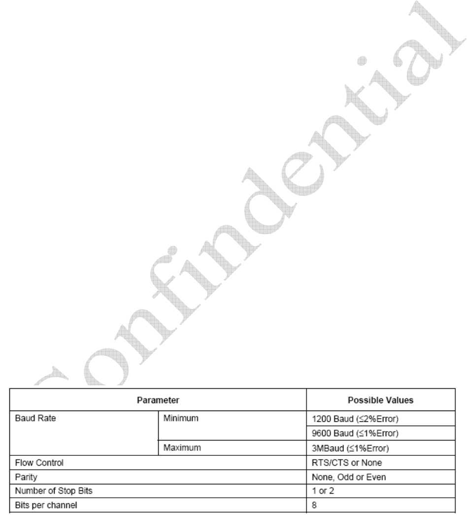
8.1 UART Interface
W2CBW003 UART interface provides a simple mechanism for communicating with other serial devices
using the RS232 standard. Four signals are used to implement the UART function:
xBT_UART_TX
xBT_UART_RX
xBT_UART_RTS
xBT_UART_CTS
When W2CBW003 is connected to another digital device, BT_UART_RX and BT_UART_TX transfer
data between the two devices. The remaining two signals, BT_UART_CTS and BT_UART_RTS, can
be used to implement RS232 hardware flow control where both are active low indicators. UART
configuration parameters, such as Baud rate and packet format, are set using W2CBW003 PS keys.
To communicate with the UART at its maximum data rate using a standard PC, an accelerated serial
port adapter card is required for the PC. An external RS232 transceiver chip is also needed.
Table 4: UART Baud Rates

Wi2Wi, Inc.Doc No. AST-PDT-DOC Rev.1.1
Data Sheet, WLAN-Bluetooth SiP– W2CBW003
Dated: October 20, 2006
The content of this document is to be treated as strictly confidential and is not to be disclosed,
reproduced or used, except as authorized in writing by Wi2Wi, Inc.
Copyright © 2006 Wi2Wi, Inc.
Page 14 of 19
The UART interface is capable of resetting W2CBW003 upon reception of a break signal. A break is
identified by a continuous logic low (0V) on the BT_UART_RX.
Figure 2: UART Break Signal
PS Key “PSKEY_UART_BAUD_RATE (0x204)” can be used to set the desired Baud Rate for UART.
8.2 USB Interface
W2CBW003 contains a full speed (12Mbits/s) USB interface that is capable of driving a USB cable
directly. No external USB transceiver is required. The device operates as a USB peripheral, responding
to requests from a master host controller such as a PC. Both the OHCI and UHCI standards are
supported. The set of USB endpoints implemented can behave as specified in the USB section of the
Bluetooth Specification v2.0 + EDR or alternatively can appear as a set of endpoints appropriate to USB
audio devices such as a set of USB speakers.
USB is a master/slave oriented system (in common with other USB peripherals). W2CBW003 only
supports USB slave operation.
8.3 PCM Interface
Pulse Code Modulation (PCM) is a standard method used to digitize audio (particularly voice) patterns
for transmission over digital communication channels. Through its PCM interface, W2CBW003 has
hardware support for continual transmission and reception of PCM data, so reducing processor overhead
for wireless headset applications. W2CBW003 offers a bi-directional digital audio interface that routes
directly into the baseband layer of the on-chip firmware. It does not pass through the HCI protocol layer.
Hardware on W2CBW003 allows the data to be sent to and received from a SCO connection.
Up to three SCO connections can be supported by the PCM interface at any one time.
W2CBW003 can operate as the PCM interface Master generating an output clock of 128, 256 or
512kHz. When configured as PCM interface slave it can operate with an input clock up to 2048kHz.
W2CBW003 is compatible with a variety of clock formats, including Long Frame Sync, Short Frame
Sync and GCI timing environments.
It supports 13 or 16-bit linear, 8-bit ȝ-law or A-law companded sample formats at 8ksamples/s, and can
receive and transmit on any selection of three of the first four slots following PCM_SYNC. The PCM
configuration options are enabled by setting the PS Key PS KEY_PCM_CONFIG.

Wi2Wi, Inc.Doc No. AST-PDT-DOC Rev.1.1
Data Sheet, WLAN-Bluetooth SiP– W2CBW003
Dated: October 20, 2006
The content of this document is to be treated as strictly confidential and is not to be disclosed,
reproduced or used, except as authorized in writing by Wi2Wi, Inc.
Copyright © 2006 Wi2Wi, Inc.
Page 15 of 19
W2CBW003 interfaces directly to PCM audio devices including the following:
xQualcomm MSM 3000 series and MSM 5000 series CDMA baseband devices
xOKI MSM7705 four channel A-law and ȝ-law CODEC
xMotorola MC145481 8-bit A-law and ȝ-law CODEC
xMotorola MC145483 13-bit linear CODEC
xSTW 5093 and 5094 14-bit linear CODECs
xW2CBW003 is also compatible with the Motorola SSI. interface
8.4 SPI Interface
W2CBW003 uses a 16-bit data and 16-bit address serial peripheral interface. Transactions may occur
when the internal processor is running or is stopped. This section describes the considerations required
when interfacing to W2CBW003 via the four dedicated serial peripheral interface terminals. Data can be
written or read one word at a time or the auto increment feature can be used to access blocks of data.
9 Antenna and Clock
W2CBW003 has two antenna interfaces, one for Bluetooth and one for WLAN. Both of these interfaces
have 50 Ohm impedance.
W2CBW003 has an internal crystal oscillator with 26 MHz frequency (frequency stability +/- 20ppm)
and requires no external clock source. This crystal provides clock for both WLAN and Bluetooth.
10 Software Specifications
10.1 Wireless LAN
xKey Features
oWEP encryption (64 bit/128 bit)
oIEEE power save mode
oDeep sleep mode
oInfrastructure and ad-hoc made
oRate adaptation
oWPA TKIP security
oWPA2
oBluetooth coexistence
xOperating System Support
oWinCE 4.2/5.0, Windows Mobile 2003, Windows Mobile 5.0

Wi2Wi, Inc.Doc No. AST-PDT-DOC Rev.1.1
Data Sheet, WLAN-Bluetooth SiP– W2CBW003
Dated: October 20, 2006
The content of this document is to be treated as strictly confidential and is not to be disclosed,
reproduced or used, except as authorized in writing by Wi2Wi, Inc.
Copyright © 2006 Wi2Wi, Inc.
Page 16 of 19
oLinux: Slakeware 9.1, Fedora Core 1.0; Kernel: 2.4.22 & above
oOther operating systems can be supported by request
10.2 Bluetooth
This section describes the key features of the BlueCore HCI stack.
xBluetooth v2.0 + EDR mandatory functionality
oEDR, 2Mbps payload data rate
oEDR, 3Mbps payload data rate
oSupport 2-DH1, 2-DH3, 2-DH5, 3-DH1, 3-DH3 and 3-DH5 packet types
oSupport 2-EV3, 2-EV5, 3-EV3 and 3-EV5 packet types
xBluetooth v1.2 mandatory functionality:
oAdaptive Frequency Hopping (AFH), including classifier
oFaster connection enhanced inquiry scan (immediate FHS response)
oLMP improvements
oParameter ranges
oSupport of AUX1 packet type
xOptional v2.0 + EDR functionality supported:
oAFH as Master and automatic channel classification
oFast connect interlaced inquiry and page scan plus RSSI during inquiry
oExtended SCO (escort), eV3 + CRC, eV4, eV5
oSCO handle
oSynchronization
xThe firmware has been written against the Bluetooth Core Specification v2.0 + EDR:
oBluetooth components: Baseband (including LC), LM and HCI
oStandard USB v2.0 (full speed) and UART HCI transport layers
oAll standard radio packet types
oFull Bluetooth data rate, up to 723.2Kbits/s asymmetric(1)
oOperation with up to seven active slaves(1)
oScatternet v2.5 operation
oMaximum number of simultaneous active ACL connections: 7(2)
oMaximum number of simultaneous active SCO connections: 3(2)
oOperation with up to three SCO links, routed to one or more slaves
oAll standard SCO voice coding, plus .transparent SCO.
oStandard operating modes: page, inquiry, page-scan and inquiry-scan
oAll standard pairing, authentication, link key and encryption operations
oStandard Bluetooth power-saving mechanisms: Hold, Sniff and Park modes, including
.Forced Hold.
oDynamic control of peers. transmit power via LMP
oMaster/slave switch
oBroadcast
oChannel quality driven data rate
Wi2Wi, Inc.Doc No. AST-PDT-DOC Rev.1.1
Data Sheet, WLAN-Bluetooth SiP– W2CBW003
Dated: October 20, 2006
The content of this document is to be treated as strictly confidential and is not to be disclosed,
reproduced or used, except as authorized in writing by Wi2Wi, Inc.
Copyright © 2006 Wi2Wi, Inc.
Page 17 of 19
oAll standard Bluetooth Test Modes
xOperating System Support
oWinCE
oLinux
oOther operating systems can be supported by request
11 Manufacturing Notes
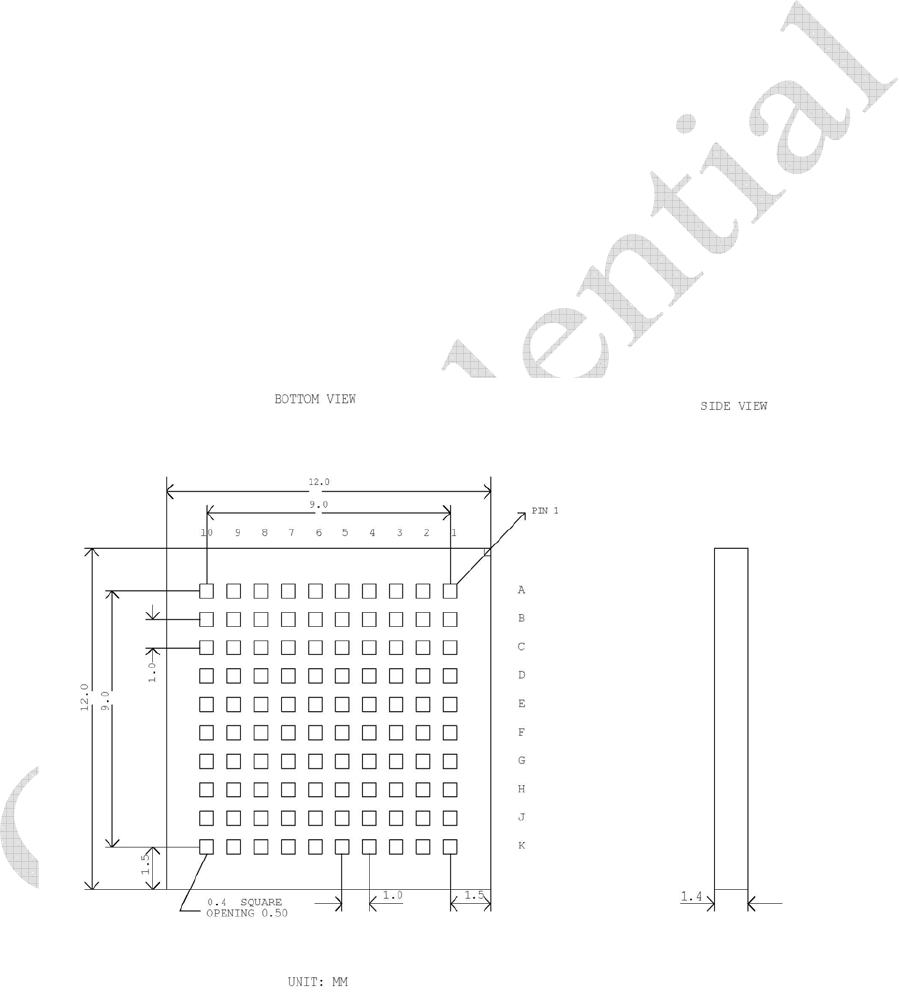
11.1 Physical Dimensions and Pin Locations
xPhysical Size: 12mm x 12mm x 1.4mm
xPad Size: 0.4mm X 0.4mm
xPad Spacing: 1mm
xPin Grid Array: 10 x 10
Figure 3: Physical Dimensions and Pin Locations
Wi2Wi, Inc.Doc No. AST-PDT-DOC Rev.1.1
Data Sheet, WLAN-Bluetooth SiP– W2CBW003
Dated: October 20, 2006
The content of this document is to be treated as strictly confidential and is not to be disclosed,
reproduced or used, except as authorized in writing by Wi2Wi, Inc.
Copyright © 2006 Wi2Wi, Inc.
Page 18 of 19
11.2 Recommended Reflow Profile
Figure 4: Recommended Reflow Profile
12 Certifications
W2CBW003 shall conform to the following standards when integrated to the W2CBW003-DEV development
system.
EMC/Immunity
xUnited States: FCC Part 15
xCanada: ICES 033
xEuropean Union: EN 55022, IEC 1004/CISPR 22
xJapan: VCCI - V series
xTaiwan: CNS 13438
xPeople’s Republic of China: GB9254
xKorea: MIC
Product Safety
xUnited States/Canada: UL/CSA 60950, UL 61010, UL 60065, CSA 601,CSA 61010,C22.2 No. 225
xEuropean Union: EN 60950, EN61010, IEC 60065, IEC 60601
xJapan: ARIB STD-T66
xPeople’s Republic of China: CNCA-08C-0312001
xRestriction of Hazardous Substances Directive (RoHS) 2002/95/EC

Wi2Wi, Inc.Doc No. AST-PDT-DOC Rev.1.1
Data Sheet, WLAN-Bluetooth SiP– W2CBW003
Dated: October 20, 2006
The content of this document is to be treated as strictly confidential and is not to be disclosed,
reproduced or used, except as authorized in writing by Wi2Wi, Inc.
Copyright © 2006 Wi2Wi, Inc.
Page 19 of 19
13 References
13.1 Specifications
xIEEE 802.11 b/g wireless LAN Specification
xSpecification of the Bluetooth System, v2.0+EDR, 04 November 2004
xSDIO full-speed card specification
xUniversal Serial Bus Specification, v2.0, 27 April 2000
13.2 Trademarks, Patents and Licenses
xTrademarks: Bluetooth, Wi-Fi, EDR
xLicenses: 88W8686 Software from Marvell; BC04-ROM Software from CSR
13.3 Other
xW2CBW003-DEV: Development Kit, WLAN-Bluetooth SiP
R50A
UltraMobilePC
User Manual

2
2
E3850
First Edition
May 2008
Copyright © 2008 ASUSTeK Computers, Inc. All Rights Reserved.
No part of this manual, including the products and software described in it, may be reproduced,
transmitted, transcribed, stored in a retrieval system, or translated into any language in any form
or by any means, except documentation kept by the purchaser for backup purposes, without the
express written permission of ASUS Telecom (“ASUS”).
Product warranty or service will not be extended if: (1) the product is repaired, modied or
altered, unless such repair, modication of alteration is authorized in writing by ASUS; or (2) the
serial number of the product is defaced or missing.
ASUS PROVIDES THIS MANUAL “AS IS” WITHOUT WARRANTY OF ANY KIND, EITHER
EXPRESS OR IMPLIED, INCLUDING BUT NOT LIMITED TO THE IMPLIED WARRANTIES
OR CONDITIONS OF MERCHANTABILITY OR FITNESS FOR A PARTICULAR PURPOSE.
IN NO EVENT SHALL ASUS, ITS DIRECTORS, OFFICERS, EMPLOYEES OR AGENTS BE
LIABLE FOR ANY INDIRECT, SPECIAL, INCIDENTAL, OR CONSEQUENTIAL DAMAGES
(INCLUDING DAMAGES FOR LOSS OF PROFITS, LOSS OF BUSINESS, LOSS OF USE OR
DATA, INTERRUPTION OF BUSINESS AND THE LIKE), EVEN IF ASUS HAS BEEN ADVISED
OF THE POSSIBILITY OF SUCH DAMAGES ARISING FROM ANY DEFECT OR ERROR IN
THIS MANUAL OR PRODUCT.
SPECIFICATIONS AND INFORMATION CONTAINED IN THIS MANUAL ARE FURNISHED
FOR INFORMATIONAL USE ONLY, AND ARE SUBJECT TO CHANGE AT ANY TIME WITHOUT
NOTICE, AND SHOULD NOT BE CONSTRUED AS A COMMITMENT BY ASUS. ASUS
ASSUMES NO RESPONSIBILITY OR LIABILITY FOR ANY ERRORS OR INACCURACIES
THAT MAY APPEAR IN THIS MANUAL, INCLUDING THE PRODUCTS AND SOFTWARE
DESCRIBED IN IT.
Products and corporate names appearing in this manual may or may not be registered
trademarks or copyrights of their respective companies, and are used only for identication or
explanation and to the owners’ benet, without intent to infringe.

3
3
Table of Contents
About this guide ................................................................5
How this guide is organized ....................................................5
Conventions used in this guide ...............................................6
Safety information .............................................................7
Transportation Precautions ...................................................8
R50A specications .........................................................9
Package contents ............................................................10
Chapter 1: Getting started
Getting to know your UMPC ...........................................12
Front features .......................................................................12
Right features .......................................................................15
Left features ..........................................................................16
Top features ..........................................................................17
Bottom features ....................................................................18
Back features ........................................................................19
Getting your UMPC ready ...............................................20
Charging the battery pack .....................................................20
Installing/removing a microSD card ......................................21
Starting up ........................................................................22
Powering on your UMPC ......................................................22
Conserving power .................................................................22
Chapter 2: Using your UMPC
Using the stylus ...............................................................26
Entering data ....................................................................26
Using the Tablet PC Input Panel ...........................................26
Calibrating the screen .....................................................28
Securing your UMPC .......................................................29
Enrolling your ngerprint data ...............................................29
Conguring the Security Protect Manager ............................30

4
4
Chapter 3: Connections
Network Connection ........................................................32
Wireless LAN Connection ...............................................33
Windows Wireless Network Connection .......................34
Connecting to a network (Vista) ............................................34
Connecting to a network (XP) ...............................................35
ASUS Wireless LAN ........................................................36
Connecting to a network ......................................................36
Bluetooth Wireless Connection .....................................38
Appendices
Optional Accessories ......................................................42
More Optional Accessories ............................................43
Optional Connections .....................................................44
Operating System and Software ....................................47
Glossary ...........................................................................48
Notices..............................................................................51
ASUS Contact information .............................................57

5
5
About this guide
This user guide provides information on the various components of the UltraMobilePC
(UMPC) and how to use them.
How this guide is organized
• Chapter 1: Getting started
This chapter describes the features of your UMPC.
• Chapter 2: Using your UMPC
This chapter provides you the steps in using your UMPC.
• Chapter 3: Connections
This chapter provides you with information on the connectivity features of your
UMPC.
• Appendices
This chapter provides you with additional information.

6
6
Conventions used in this guide
To make sure that you perform certain tasks properly, take note of the following
symbols used throughout this manual.
DANGER/WARNING: Information to prevent injury to yourself
when trying to complete a task.
CAUTION: Information to prevent damage to the components
when trying to complete a task.
NOTE: Tips and additional information to help you complete a
task.
IMPORTANT: Instructions that you MUST follow to complete a
task.
7
7
INPUT RATING: Refer to the
rating label on the bottom of
the UMPC and ensure that your
power adapter complies with the
rating.
DO NOT throw the UMPC in
municipal waste. Check local
regulations for disposal of
electronic products.
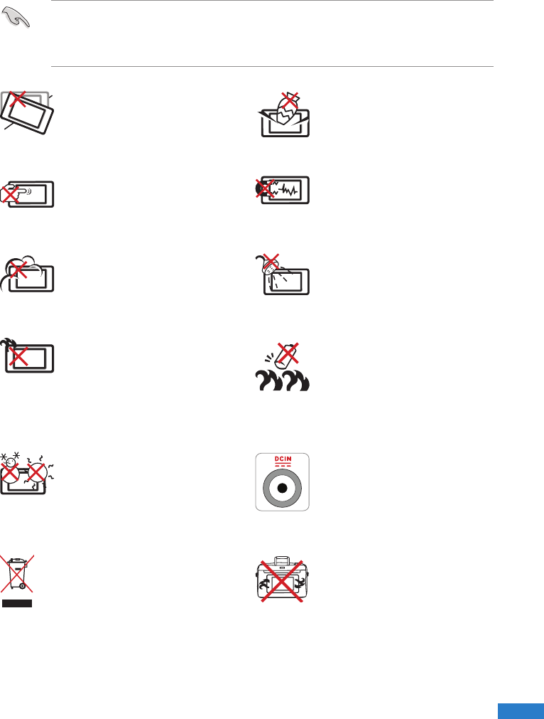
Safety information
IMPORTANT! Disconnect the AC power and remove the battery pack before cleaning
Wipe the UMPC using a clean cellulose sponge or chamois cloth dampened with a
solution of nonabrasive detergent and a few drops of warm water and remove any
extra moisture with a dry cloth.
DO NOT expose to or use near
liquids, rain, or moisture. DO
NOT use the modem during an
electrical storm.
DO NOT expose to dirty or dusty
environments. DO NOT operate
during a gas leak.
SAFE TEMP: This UMPC should
only be used in environments
with ambient temperatures
between 5°C (41°F) and 35°C
(95°F)
Battery safety warning:
DO NOT throw the battery in re.
DO NOT short circuit the
contacts.
DO NOT disassemble the
battery.
DO NOT expose to strong
magnetic or electrical elds.
DO NOT place on uneven or
unstable work surfaces. Seek
servicing if the casing has been
damaged.
DO NOT place or drop objects
on top and do not shove any
foreign objects into the UMPC.
DO NOT scratch the display
panel. Do not place together with
small items that may scratch or
enter the UMPC vents.
DO NOT leave the UMPC on
your lap or any part of the body
in order to prevent discomfort or
injury from heat exposure.
DO NOT carry or cover a UMPC
that is powered ON with any
materials that will reduce air
circulation such as a carrying
bag.

8
8
Transportation Precautions
To prepare the UMPC for transport, you should turn it OFF and disconnect all
external peripherals to prevent damage to the connectors. The hard disk drive’s
head retracts when the power is turned OFF to prevent scratching of the hard disk
surface during transport. Therefore, you should not transport the UMPC while the
power is still ON.
Cover Your UMPC
You can purchase an optional carrying case to protect it from dirt, water, shock, and
scratches.
CAUTION: The UMPC’s surface is easily dulled if not properly cared for. Be careful not
to rub or scrape the UMPC surfaces when transporting your UMPC.
Charge Your Batteries
If you intend to use battery power, be sure to fully charge your battery pack and any
optional battery packs before going on long trips. Remember that the power adapter
charges the battery pack as long as it is plugged into the computer and an AC power
source. Be aware that it takes much longer to charge the battery pack when the UMPC
is in use.
Airplane Precautions
Contact your airline if you want to use the UMPC on the airplane. Most airlines will
have restrictions for using electronic devices. Most airlines will allow electronic use only
between and not during takeoffs and landings.
CAUTION: There are three main types of airport security devices: X-ray machines
(used on items placed on conveyor belts), magnetic detectors (used on people walking
through security checks), and magnetic wands (hand-held devices used on people
or individual items). You can send your UMPC and diskettes through airport X-ray
machines. However, it is recommended that you do not send your UMPC or diskettes
through airport magnetic detectors or expose them to magnetic wands.
9
9
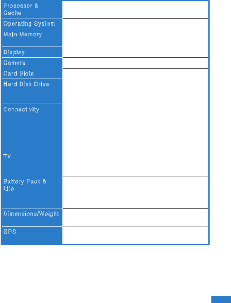
R50A specications
Processor &
Cache
Operating System
Main Memory
Display
Camera
Card Slots
Hard Disk Drive
Connectivity
TV
Battery Pack &
Life
Dimensions/Weight
GPS
Intel Fred (Silverthorne) CPU Z520 1.33GHz, 512L2
cache
Microsoft Windows® Vista Ultimate
On board 1GB DDR2-400 (667 down grade) DRAM
design
5.6”active matrix TFT, 1024 x 600 pixel
2.0 megapixel auto-focus camera
1 Micro-SD card slot, push/push type
SSD HDD 32GB
SSD HDD 16GB
SSD HDD 8GB
Integrated USB 802.11b/g
Bluetooth 2.0+EDR
Sierra 3G with Voice solution
SIM card connector build in under battery is suggested
Support Band 4 or 5 with difference antenna depends on
mechanical dimension.
Optional DVB-T mini-Card TV module support dual
antenna and mobility to 120kM/hr
External Antenna for TV
Output : 12V/15W DC
Input : 100~240V AC, 50/60Hz universal
3/ 2 pin compact power supply system
Optional accessory : 12V cable for car charging
199 x 97 x 28.4 (mm)
520 g (for Primary Battery)
Built-in GPS
One RF connector for external antenna

10
10
NOTE: If any of the above items is damaged or missing, contact your retailer.
Package contents
Check your device package for the following items:
Standard Items
•
R50A UMPC •
External ODD Pack*
•
AC adapter • GPS Pack*
•
Headset •
External GPS antenna*
•
VGA cable •
External TV antenna*
•
Mini-USB audio cable •
USB mouse*
• Installation CD •
Bluetooth mouse*
• USB tablet bi-fold keyboard with USB
cable
*Optional

11
11
Getting started
Chapter 1
• Getting to know your UMPC
• Getting your device ready
• Starting up
12
12
Getting to know your UMPC
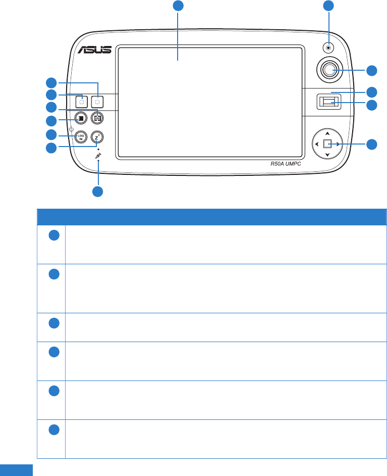
Front features
Features
1Display Panel
The 5.6-inch active matrix, 1024 x 600 resolution TFT LCD screen provides
you with excellent viewing similar to that of desktop monitors.
2Camera
The 2.0 megapixel auto-focus built-in camera allows you to take pictures
or video clips. This can also be used for video conferencing and other
interactive applications.
3Mouse pointer
This a pointing device that mimics the functions of a desktop mouse.
4Status indicator
This indicates the status of your battery, drive activity, WLAN, and Bluetooth.
Refer to the section
Status indicators
on page 16 for more details.
5Fingerprint sensor
The built-in ngerprint sensor allows you to use your ngerprint as your
identity key for added security.
6Arrow/Enter keys
The arrow keys (left, right, up, down) and the enter key have the same
functions as that on the keyboard.
1 2
3
4
5
6
7
8
9
10
11
12
13

13
13
Features
7Microphone (Built-in)
The built-in mono microphone is used for video conferencing, voice
narrations, or simple audio recordings.
8Sleep/Standby Mode key
Press this key to put your UMPC into Sleep/Standby mode. Slide down the
power switch to awaken your UMPC from its Sleep/Standby mode.
9LOGIN key
The LOGIN button sends a [Ctrl][Alt][Del] keyboard combination to the
operating system to show Windows Security for logging in/off, locking,
shutting down, showing task manager, or changing passwords. This special
login feature is also known as Secure Attention Sequence (SAS).
10 UMPC Settings key
This allows you to set the brightness, volume, resolution or power mode of
your UMPC.
11 Windows® Media Center key
This launches the Windows® Media Center which allows you to view and
play media les such as video clips, music les, or movies.
12 Left key
This key mimics the left-click action of a desktop mouse.
13 Right key
This key mimics the right-click action of a desktop mouse.
14
14
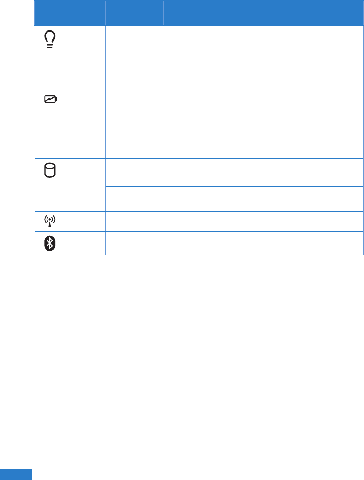
Status indicators
Icon LED
Indicator
Status
Power
Blue The UMPC is turned on.
Blinking
blue The UMPC is in the Sleep/Standby mode.
Off The UMPC is turned off or in Hibernation mode.
Battery Red The battery is charging.
Blinking
red The battery capacity is less than 10%.
Off The battery is fully-charged.
HDD Blue Drive Activity Indicator
The UMPC is accessing the hard disk drive.
Blinking
blue The UMPC is shutting down.
WLAN On The built-in wireless LAN (WLAN) is enabled.
Bluetooth On The built-in Bluetooth function is activated.
15
15
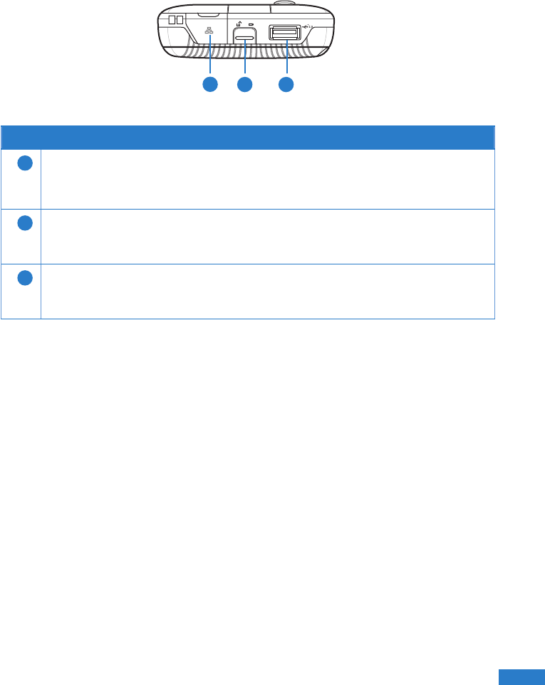
Right features
12 3
Features
1USB Bluetooth port
This contains the USB Bluetooth port. Insert a USB Bluetooth dongle to
activate the UMPC’s built-in Bluetooth function.
2Battery Lock
Keeps the battery secure. Press up then slide the back cover downward to
open the battery.
3USB Port (2.0/1.1)
Insert USB2.0 or USB1.1 devices such as keyboards, pointing devices, hard
disk drives, printers and scanners into this port.
16
16
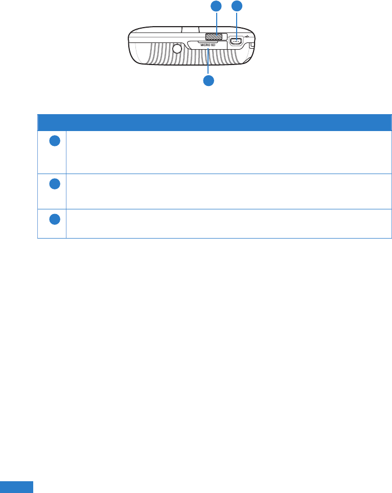
Left features
12
3
Features
1Power switch
Turns on/off the UMPC and puts it on Sleep/Standby or Hibernation mode.
2Mini-USB port
Insert an external USB keyboard into this port.
3MicroSD slot
Insert a microSD card into this slot.