ASUSTeK Computer R50AWI22 ULTRA MOBILE PC User Manual USERS MANUAL 2
ASUSTeK Computer Inc ULTRA MOBILE PC USERS MANUAL 2
Contents
- 1. USERS MANUAL 1
- 2. USERS MANUAL 2
USERS MANUAL 2
17
17
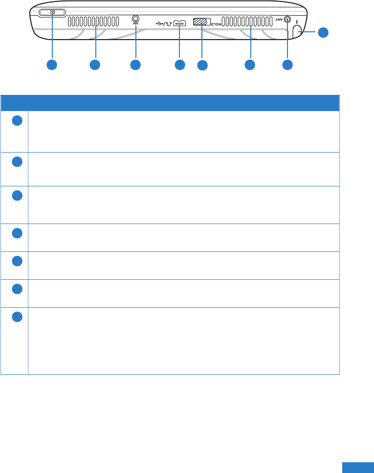
Top features
1 2 3 4 5
7
2 6
Features
1Camera key
Press to take pictures or video clips.
2Speaker system
The built-in speaker system allows you to hear rich and vibrant audio/sound.
3Power (DC) port
Insert the AC adapter into this port to connect your UMPC to an external
power source.
4Headphone jack
Insert a headphone into this port.
5Hold key
Move this key to the left to disable the buttons and LCD of th UMPC.
6Antenna port
Attach an external antenna for a better signal reception.
7Stylus
Use this stylus to select items or navigate through the programs in your
UMPC.
Like the mouse pointer on your UMPC, the stylus also mimics the functions
of a desktop mouse such as left-click, double-click, or right-click.
18
18
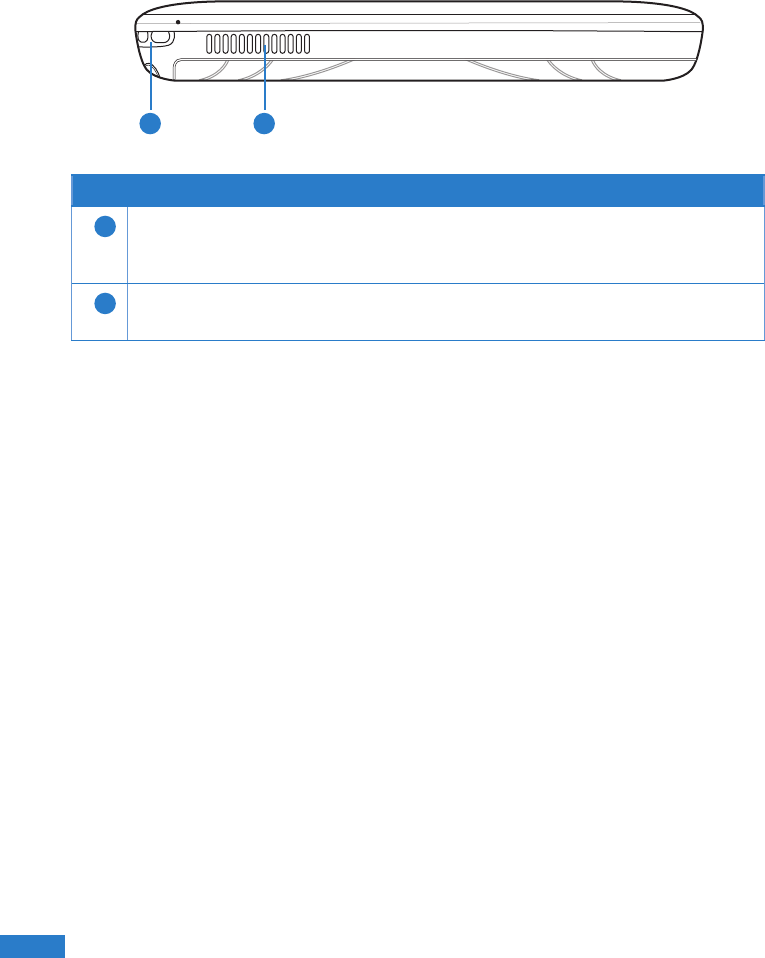
Bottom features
Features
1Wrist strap hook
Attach a wrist strap into this hook to prevent prevent accidentally dropping prevent accidentally dropping
the UMPC when holding it in your hands.
2Air vent
The air vent allows cool air to enter and warm air to exit the system.
1 2
19
19
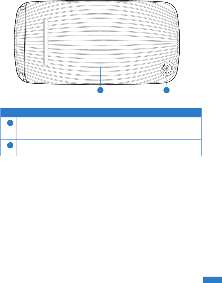
Back features
1 2
Features
1Battery Pack
The battery pack provides power to the UMPC. To charge the battery,
connect the UMPC to an external power source using the AC adapter.
2Camera lens
This is a 2.0 megapixel auto focus camera.
20
20
Getting your UMPC ready
Before using the UMPC for the rst time, ensure that the battery pack is fully charged.
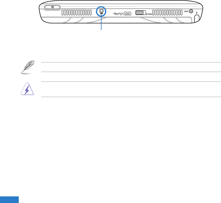
Charging the battery pack
Your UMPC package comes with a universal AC-DC adapter which charges the battery
pack, and in turn supplies power to your UMPC. You may connect the adapter to a 100-
120V or 220V-240V outlet without setting switches or using power converters.
To charge the battery pack, connect the DC plug of the adapter to the DC port located
at the top of the UMPC, then connect the other end of the adapter to a 100-120V or
220V-240V power outlet.
Power DC port
NOTE: Use only the AC-DC adapter provided in your UMPC package.
WARNING: The adapter may become warm to hot when in use. Keep the adapter
away from your body.
21
21
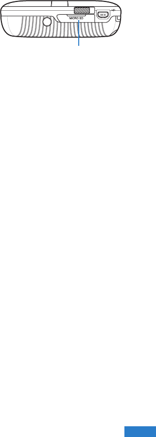
Installing/removing a microSD card
Your UMPC is equipped with a microSD card slot. A microSD card provides you with
additional storage space for your les.
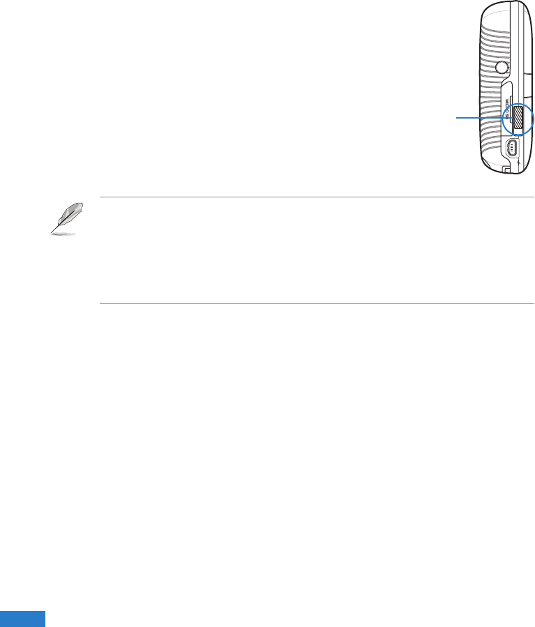
To install the microSD card:
1. Locate the microSD card slot at the left side of
the UMPC.
2. Lift to open the slot cover.
3. With the golden ngers facing down, insert the
microSD into the slot until it snaps properly.
4. Close the slot cover.
To remove the microSD card:
1. Lift to open the slot cover.
2. Push the card until it ejects out, then remove the microSD card.
3. Close the slot cover.
microSD card slot
22
22
Starting up
Powering on your UMPC
Like a regular desktop PC, your UMPC automatically runs a series of diagnostic tests
called Power-On Self Test (POST) upon turning it on. After POST is completed, your
UMPC boots up, then its Windows® operating system starts automatically.
To power on your UMPC:
1. Locate the power switch at the left side of your UMPC.
2. Press the switch down to turn on the UMPC. The
UMPC boots up, then the operating system starts
automatically.
3. Use your UMPC as you would use a regular desktop
PC.
Power switch
NOTES:
• If your UMPC does not turn on, check if the Hold key is in Hold (red) mode or if the
battery pack is charged.
• To set or modify the system conguration, press [F2] upon boot up to enter the
BIOS setup.
Conserving power
Your UMPC is equipped with power saving features which helps conserve power and
maximizes your UMPC’s performance.
Selecting a power plan
One of these power saving features is the power plan which is a collection of advanced
power management settings.
To select a power plan:
1. From your UMPC screen, go to Start > Control Panel > Mobile PC > Change
battery settings.
2. Select or customize a power plan from the list of existing power plans.
23
23
Setting your UMPC on Sleep or Hibernate mode
If you want a quick and simple way to conserve power, you can set your UMPC on
Sleep or Hibernate mode:
• Sleep is the same as Suspend-to-RAM (STR). This function stores your current
data and status in RAM while many components are turned OFF. Because RAM is
volatile, it requires power to keep (refresh) the data.
• Hibernate is the same as Suspend-to-Disk (STD) and stores your current data and
status on the hard disk drive. By doing this, RAM does not have to be periodically
refreshed and power consumption is greatly reduced but not completely eliminated
because certain wake-up components like LAN needs to remain powered.
“Hibernate” saves more power compared to “Sleep”.
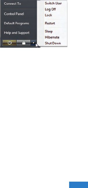
To set your UMPC on Sleep or Hibernate mode:
1. From your UMPC screen, go to Start.
2. Click the arrow next to the lock icon to display the
menu.
3. From the menu, select either Sleep or Hibernate.

24
24

25
25
Using your UMPC
Chapter 2
• Using the stylus
• Entering data
• Calibrating the screen
• Securing your UMPC

26
26
Using the stylus
Use the stylus to select items or navigate through programs on your UMPC, as well as
write characters or text using the input panel on your UMPC.
Like the mouse pointer on the UMPC, the stylus also mimics the functions of a desktop
mouse.
TO DO THIS
Select an item Tap the screen once with the stylus.
Run an item Tap the screen twice with the stylus.
Move an item Tap and drag with the stylus to move the item.
Right-click Tap and hold the screen. When the mouse icon appears, tap the right side of
the mouse icon.
Entering data
You may use a bi-fold keyboard or the Tablet PC Input Panel to write text, characters,
or symbols on your UMPC.
NOTES:
• The bi-fold keyboard is an optional accessory and is not included in your UMPC
package.
• Refer to the section Optional Accessories in the Appendices for more details on
using a bi-fold keyboard with your UMPC.
Using the Tablet PC Input Panel
The Tablet PC Input Panel tool on the UPMC enables you to enter text on a word
processor such as Notepad or WordPad without using a standard keyboard. The Tablet
PC Input Panel provides you with these three input methods: Writing Pad, Character
Pad, and On-screen Keyboard.
Using the Writing Pad
The Writing Pad allows you to write continuously, and converts your handwriting to
typed text.
To use the Writing Pad:
1. Launch a word processor such as WordPad. To do this, go to Start > All Programs
> Accessories > WordPad.
27
27
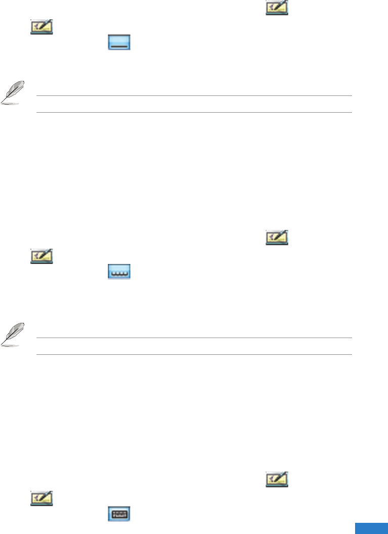
2. Tap the screen with the stylus. The Tablet PC Input Panel icon appears.
3. Tap . The Tablet PC Input Panel appears.
4. On the input panel, tap . The Writing Pad appears.
5. Using your stylus, write on the screen as you would write on a piece of paper.
6. When done, tap Insert. The text you wrote appears on the Wordpad.
NOTE: Ensure that you write legibly.
Using the Character Pad
The Character Pad converts each of your handwritten text, symbol, or character into
typed text one at a time.
To use the Character Pad:
1. Launch a word processor such as WordPad. To do this, go to Start > All Programs
> Accessories > WordPad.
2. Tap the screen with the stylus. The Tablet PC Input Panel icon appears.
3. Tap . The Tablet PC Input Panel appears.
4. On the input panel, tap . The Character Pad appears.
5. Using your stylus, write on the screen as you would write on a piece of paper. The
Character Pad converts each handwritten character or text into typed text.
6. When done, tap Insert. The text you wrote appears on the Wordpad.
NOTE: Ensure that you write legibly.
Using the On-screen Keyboard
The on-screen keyboard is similar to a standard keyboard, except that you tap your
stylus on it to enter text or characters.
To use the On-screen Keyboard:
1. Launch a word processor such as WordPad. To do this, go to Start > All Programs
> Accessories > WordPad.
2. Tap the screen with the stylus. The Tablet PC Input Panel icon appears.
3. Tap . The Tablet PC Input Panel appears.
4. On the input panel, tap . The On-screen Keyboard appears.
5. Using your stylus, tap the keys to enter text.
28
28
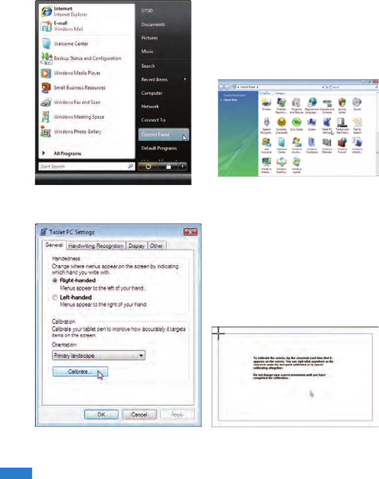
1. Launch Control Panel from Windows
Start.
3. Click the Calibrate button on the
“General” page.
2. Double click Tablet PC Settings
icon.
4. Carefully tap the center of each cross
hair that appears near each corner to
complete the calibration process.
Calibrating the screen
Calibrating the screen ensures that the touchscreen feature of the UMPC works
properly when tapped with the stylus or with your nger.
29
29
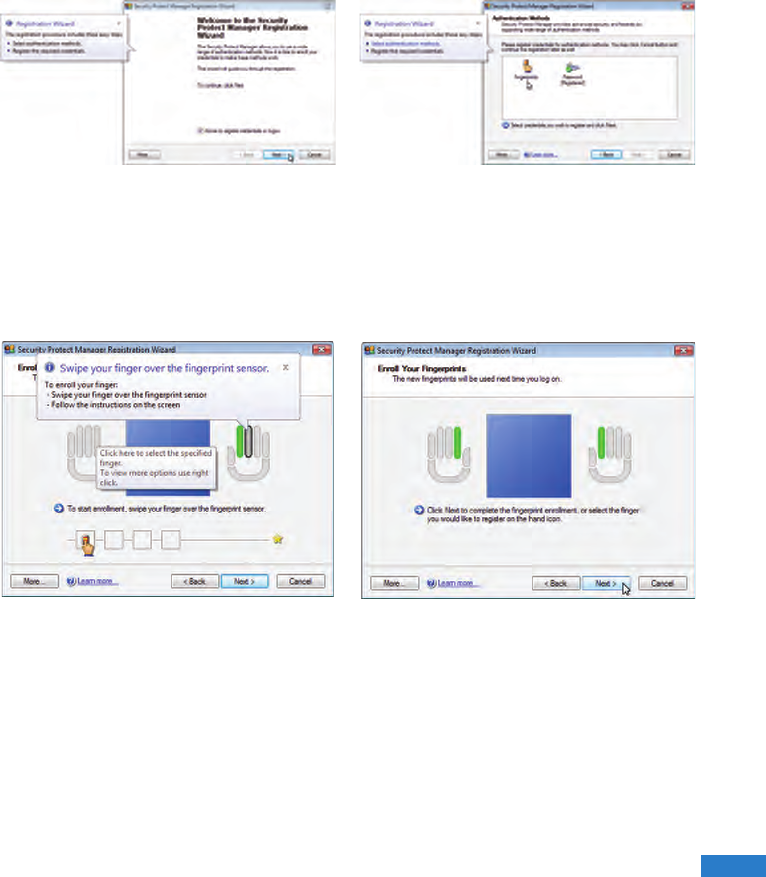
Securing your UMPC
Enrolling your ngerprint data
The ngerprint sensor on the UMPC makes your device more secure from
unauthorized access. With the ngerprint sensor, you can enter your ngerprint data as
your authentication mechanism for your UMPC.
1. This wizard will automatically start
when TPM is enabled in BIOS after
setting security passwords. Click Next
to continue.
2. Select “Fingerprints” and click Next.
3. Select a nger on the diagram, and
swipe that nger on the ngerprint
sensor. Swipe your nger multiple
times for verication.
4. Click Next to enroll another nger.
Enroll at least two ngers for your
ngerprint data.
30
30
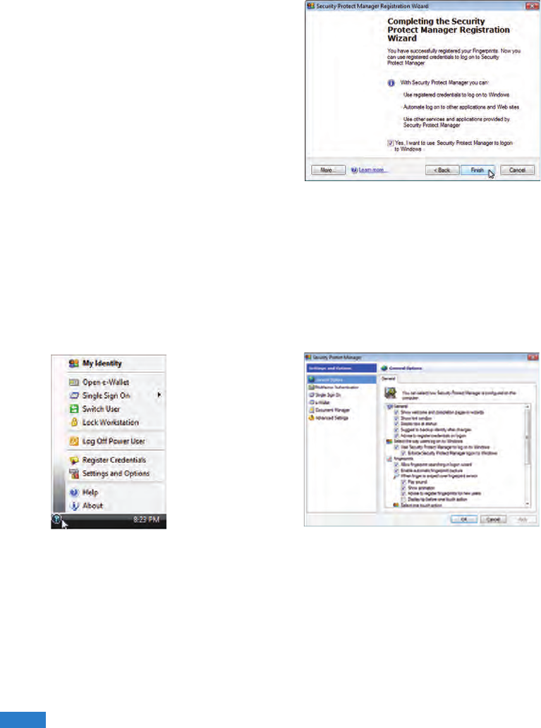
5. Click Finish when done. You need
to congure the Security Protect
Manager to enable ngerprint settings.
1. Right-click the icon on the taskbar and
select “Settings and Options”.
2. Select “General Options” and
“Single Sign On” and congure your
preferences.
Conguring the Security Protect Manager
The Security Protect Manager enables you to use your registered credentials, such as
your ngerprint data, to log on to Windows and other applications.
To congure the Security Protect Manager:

31
31
Connections
Chapter 3
• Network Connection
• Wireless LAN Connection
• Windows® Wireless Network Connection
• ASUS Wireless LAN
• Bluetooth Wireless Connection
32
32
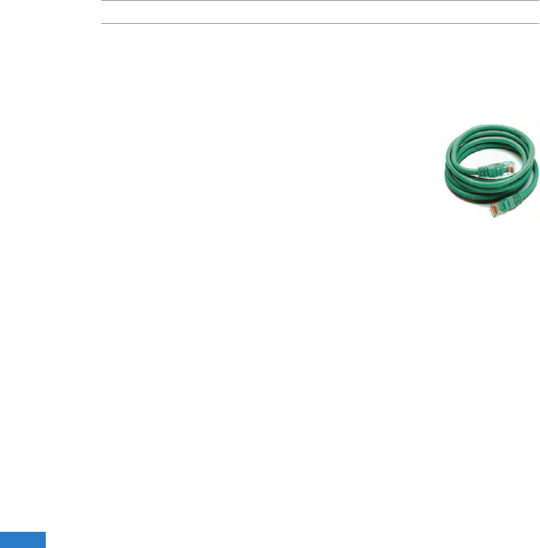
Network Connection
Connect a network cable, with RJ-45 connectors on each end, to the modem/network
port on the Notebook PC and the other end to a hub or switch. For 100 BASE-TX /
1000 BASE-T speeds, your network cable must be category 5 or better (not category
3) with twisted-pair wiring. If you plan on running the interface at 100/1000Mbps, it
must be connected to a 100 BASE-TX / 1000 BASE-T hub (not a BASE-T4 hub). For
10Base-T, use category 3, 4, or 5 twisted-pair wiring. 10/100 Mbps Full-Duplex is
supported on this Notebook PC but requires connection to a network switching hub
with “duplex” enabled. The software default is to use the fastest setting so no user-
intervention is required.
NOTE: 1000BASE-T (or Gigabit) is only supported on selected models.1000BASE-T (or Gigabit) is only supported on selected models.
Twisted-Pair Cable
The cable used to connect the Ethernet card to a host (generally a Hub or Switch) is
called a straight-through Twisted Pair Ethernet (TPE). The end connectors are called
RJ-45 connectors, which are not compatible with RJ-11 telephone
connectors. If connecting two computers together without a hub in
between, a crossover LAN cable is required (Fast-Ethernet model).
(Gigabit models support auto-crossover so a crossover LAN cable is
optional.)
33
33
Wireless LAN Connection (on selected models)
The optional built-in wireless LAN is a compact easy-to-use wireless Ethernet adapter.
Implementing the IEEE 802.11 standard for wireless LAN (WLAN), the optional built-
in wireless LAN is capable of fast data transmission rates using Direct Sequence
Spread Spectrum (DSSS) and Orthogonal Frequency Division Multiplexing (OFDM)
technologies on 2.4GHz/5GHz frequencies. The optional built-in wireless LAN is
backward compatible with the earlier IEEE 802.11 standards allowing seamless
interfacing of wireless LAN standards.
The optional built-in wireless LAN is a client adapter that supports Infrastructure
and Ad-hoc modes giving you exibility on your existing or future wireless network
congurations for distances up to 40 meters between the client and the access point.
To provide efcient security to your wireless communication, the optional built-in
wireless LAN comes with a 64-bit/128-bit Wired Equivalent Privacy (WEP) encryption
and Wi-Fi Protected Access (WPA) features.
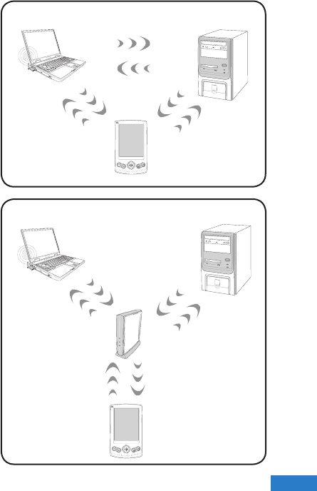
Ad-hoc mode
The Ad-hoc mode allows the Notebook
PC to connect to another wireless
device. No access point (AP) is
required in this wireless environment.
(All devices must install optional
802.11 wireless LAN adapters.)
Infrastructure mode
The Infrastructure mode allows the
Notebook PC and other wireless
devices to join a wireless network
created by an Access Point (AP) (sold
separately) that provides a central link
for wireless clients to communicate
with each other or with a wired
network.
(All devices must install optional
802.11 wireless LAN adapters.)
PDA
Access
Point
Desktop PCNotebook PC
Desktop PC
PDA
Notebook PC
34
34
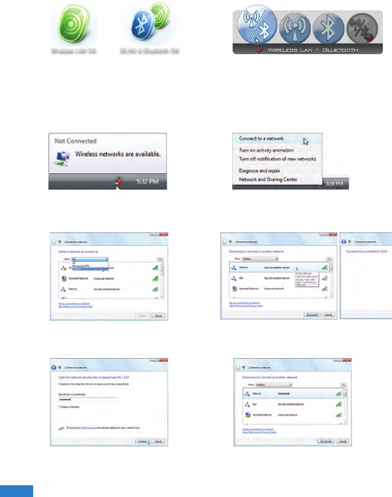
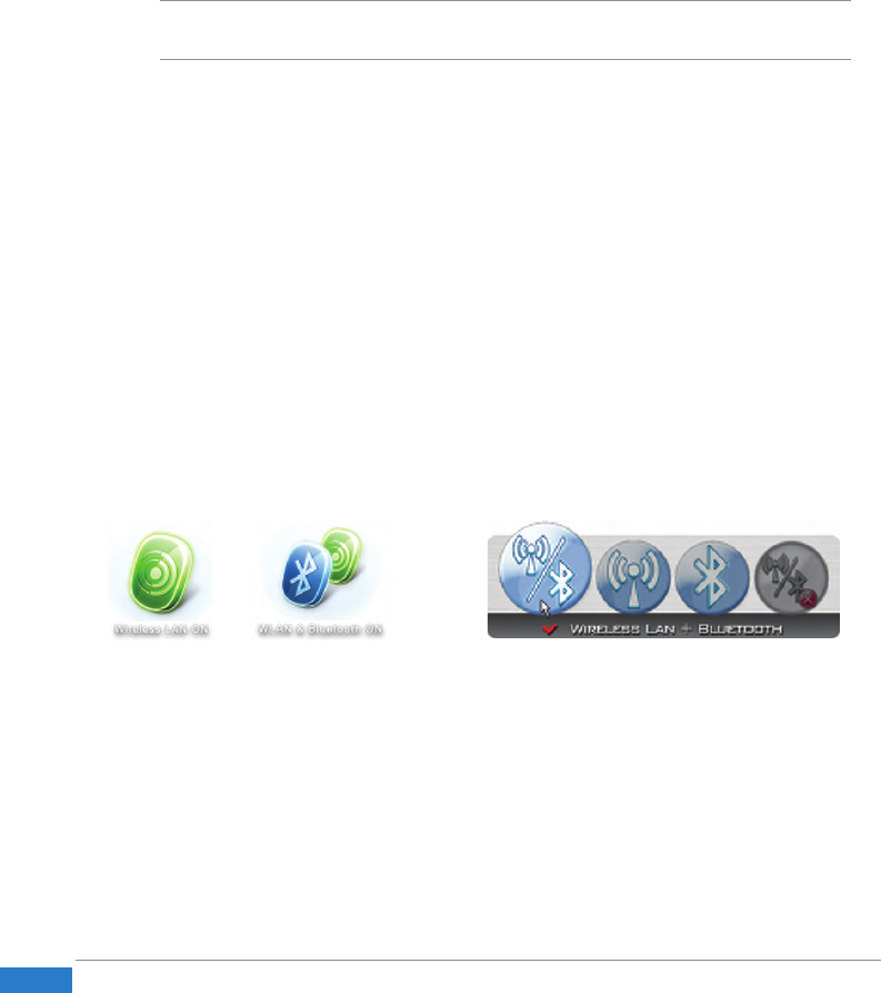
1. Press [WIRELESS] switch repeatedly
until Wireless LAN ON or WLAN &
Bluetooth ON is shown.
Windows Wireless Network Connection
Connecting to a network (Vista)
2. You should see the “Not Connected”
network icon.
4. Select “Show Wireless” if you have
many networks in your area.
5. Select the wireless network you want
to connect to.
6. When connecting, you may have to
enter a password.
7. After connection has been established,
“Connected” will be shown.
1b. Or double click the Wireless Console
icon on the taskbar and select either
the 1st icon to activate both Wireless
& Bluetooth, or select the 2nd icon for
Wireless activation only.
3. Right click on the WLAN icon and
select Connect to a network.
35
35
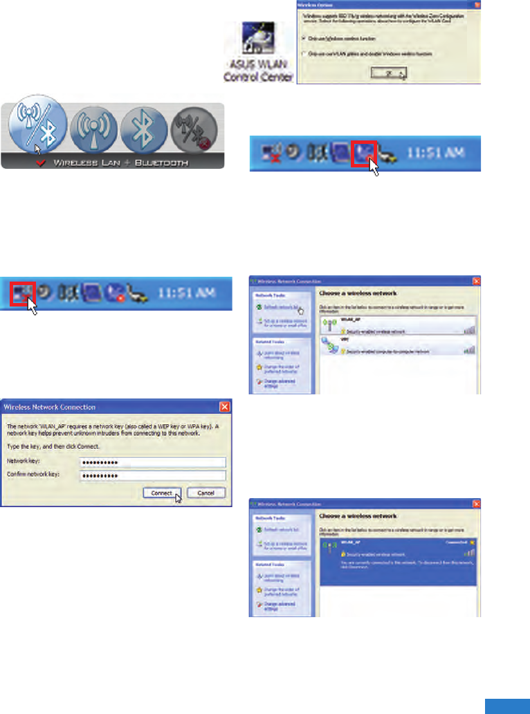
Connecting to a network (XP)
Using Windows XP wireless settings
require that you select this option in
the ASUS WLAN Control Center.
1. Press [WIRELESS] switch repeatedly
until Wireless LAN ON or WLAN &
Bluetooth ON is shown.
2. Double click the WLAN icon on the
taskbar.
3. Select Refresh network list from the
left side menu and a list of available
network within your area and its signal
strength will show. Select your network
and click on Connect.
4. When connecting, you may have to
enter a password.
5. After connection has been established,
“Connected” will be shown on the
right side above the signal strength
indicator.
1b. Or double click the Wireless Console
icon on the taskbar and click on the
1st icon to activate both Wireless &
Bluetooth, or select the 2nd icon for
Wireless activation only.
36
36
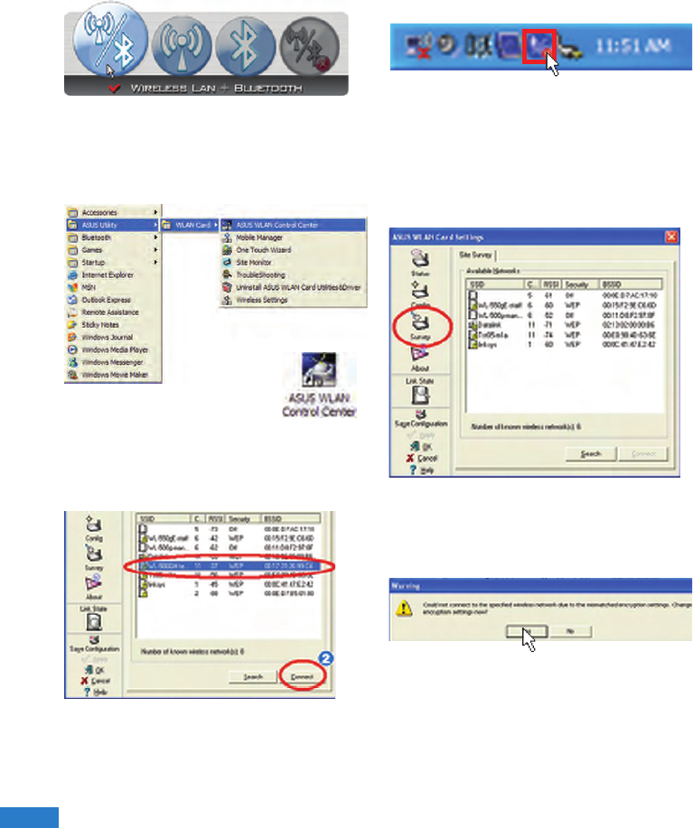
ASUS Wireless LAN (on selected models)
Connecting to a network
Using ASUS wireless settings require that you select this option in the ASUS WLAN
Control Center.
2. Double click the icon on the desktop or
click Start | Programs | ASUS Utility
| WLAN Card | ASUS WLAN Control
Center.
3. On the left hand side menu, click
Survey to start scanning for available
networks in your area.
4. The list will show all available
networks within your area. Select the
network you want and click Connect.
5. If the selected Network has security
settings, you may be required to enter
a password.
1. Press [WIRELESS] switch repeatedly until
Wireless LAN ON or WLAN & Bluetooth
ON is shown.
1b. Or double click the Wireless Console
icon on the taskbar and click on the
1st icon to activate both Wireless &
Bluetooth, or select the 2nd icon for
Wireless activation only.
37
37
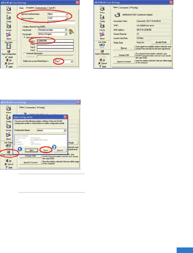
6. Click the Encryption tab to congure
the Network Authentication mode and
Password.
7. The Status tab will show connection
status and details.
Note: Click “Save Conguration” and
“Save” to remember settings for this
network.
38
38
Bluetooth Wireless Connection (on selected
models)
Notebook PCs with Bluetooth technology eliminates the need for cables for connecting
Bluetooth-enabled devices. Examples of Bluetooth-enabled devices may be Notebook
PCs, Desktop PCs, mobile phones, and PDAs.
Note: If your Notebook PC did not come with built-in Bluetooth, you need to connect a
USB or ExpressCard Bluetooth module in order to use Bluetooth.
Bluetooth-enabled mobile phones
You can wireless connect to your mobile phone. Depending on your mobile phone’s
capabilities, you can transfer phone book data, photos, sound les, etc. or use it as a
modem to connect to the Internet. You may also use it for SMS messaging.
Bluetooth-enabled computers or PDAs
You can wireless connect to another computer or PDA and exchange les, share
peripherals, or share Internet or network connections. You may also make use of
Bluetooth-enabled wireless keyboard or mouse.
Turning ON and Launching Bluetooth Utility (Vista)
This process can be used to add most Bluetooth devices. See Appendix for complete
process.
1. Press [WIRELESS] switch repeatedly
until Bluetooth ON or WLAN &
Bluetooth ON is shown.
1b. Or double click the Wireless Console
icon on the taskbar and select either
the 1st icon to activate both Wireless
& Bluetooth, or select the 3rd icon for
Bluetooth activation only.

39
39
2. Select Add a Bluetooth Device on
the taskbar men.
2b. Or Launch Bluetooth Devices from
the Windows Control Panel.

40
40

41
41
Appendices
Appendices
• Optional Accessories
• Optional Connections
• Glossary
• Notices
• ASUS Contact information
42
42
Optional Accessories
These items, if desired, come as optional items to complement your UMPC.
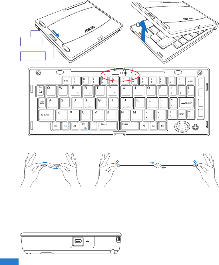
Slide latch on the top to lock the keyboard in the open position.
Extend: Pull the USB
connectors apart (not fully)
to extend the mini-USB
cable. (Note: If you pull too
much, it will retract.)
Retract: Pull the USB connectors fully apart and allow
the internal spring to automatically retract the mini-
USB cable.
Connect the mini-USB cable to the
foldable USB keyboard (left side) and
the mini-USB port on the UMPC (left
side).
Slide latch
to open.
Mini-USB
Port
PgUp
PgDn
PrtSc
Break
Pause
SysRq
F1 F2 F3 F4 F5 F6 F7F7 F8F8 F9F9
F 10F 10
F11F1
F 1F 12
Home
End
LOCK UNLOCK
Foldable USB Keyboard
43
43
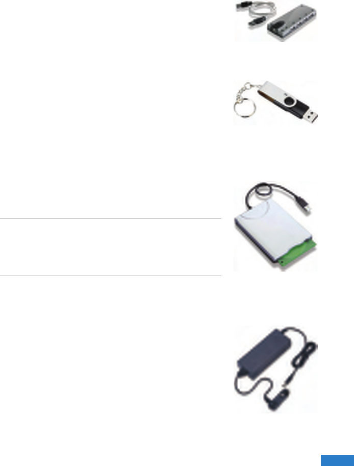
USB Hub (Optional)
Attaching an optional USB hub will increase your USB ports
and allow you to quickly connect or disconnect many USB
peripherals through a single cable.
USB Flash Memory Disk
A USB ash memory disk is an optional item that can replace the
1.44MB oppy disk and provide storage up to several hundred
megabytes, higher transfer speeds, and greater durability. When
used in current operating systems, no drivers are necessary.
USB Floppy Disk Drive
An optional USB-interface oppy disk drive can accept a
standard 1.44MB (or 720KB) 3.5-inch oppy diskette.
WARNING! To prevent system failures, use Windows
“Safely Remove Hardware” on the taskbar before
disconnecting the USB oppy disk drive. Eject the oppy
disk before transporting the Notebook PC to prevent
damage from shock.
Vehicle Power Adapter
The vehicle power adapter provides a source of power for
using the Notebook PC and/or charging the Notebook PC’s
battery pack while in transit when no AC power is available.
This product is an essential tool for today’s mobile professional.
Your purchase will enhance the power, performance, and
versatility of your portable computer while traveling on the
road or on the sea. The Vehicle Power Adapter can be used in
vehicles or boats using a standard cigarette lighter socket. The
Vehicle Power Adapter accepts input ranges from 10.8VDC
(Volts - Direct Current) to 16VDC and provides 19VDC up to
120W (Watts).
More Optional Accessories
These items, if desired, come as optional items to complement your UMPC.
44
44
Optional Connections
These items, if desired, may be purchased from third-parties.
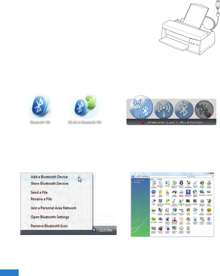
Printer Connection
One or more USB printers can be simultaneously used
on any USB port or USB hub.
Bluetooth Mouse Setup (optional)
This process can be used to add most Bluetooth devices in Windows operating system.
2. Select Add a Bluetooth Device on
the taskbar menu.
2b. Or Launch Bluetooth Devices from
the Windows Control Panel.
1. Press [WIRELESS] switch repeatedly
until Bluetooth ON or WLAN &
Bluetooth ON is shown.
1b. Or double click the Wireless Console
icon on the taskbar and select either
the 1st icon to activate both Wireless
& Bluetooth, or select the 3rd icon for
Bluetooth activation only.
45
45
R
E
S
E
T
OFF ON
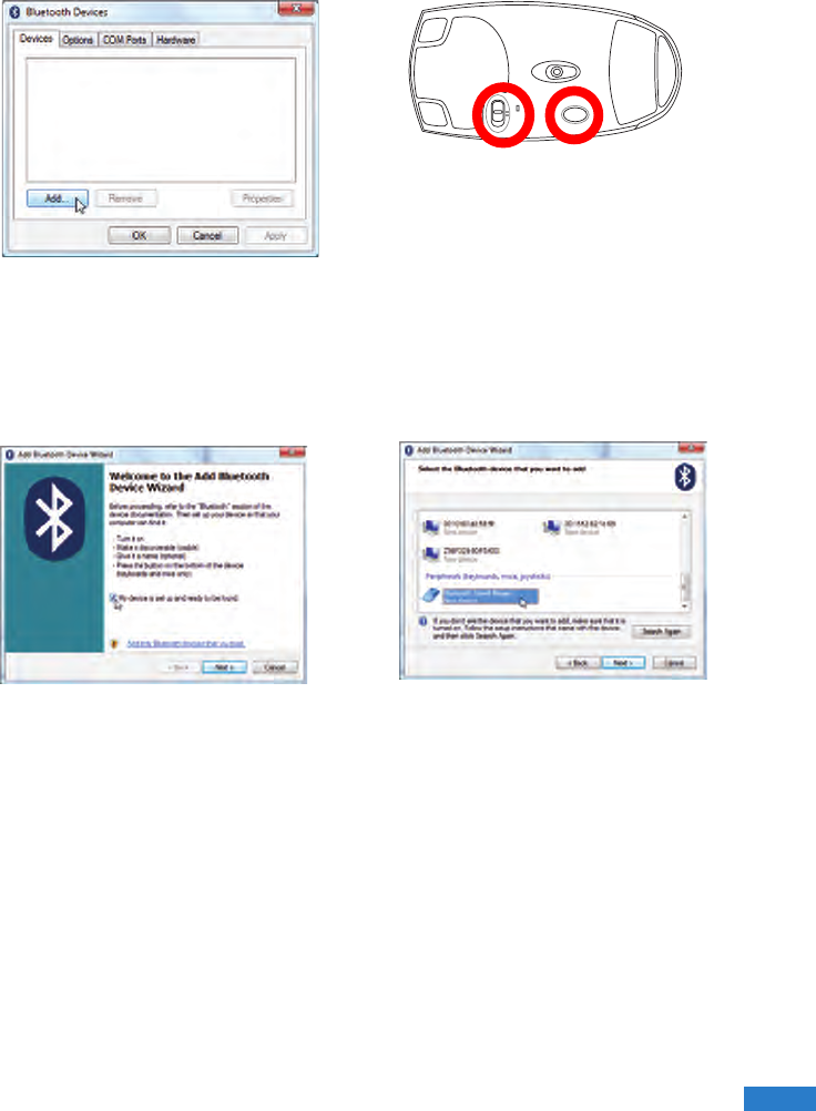
3. Prepare the Bluetooth mouse.
• Install two “AA” batteries.
• Turn ON the power switch on the
bottom of the mouse. The bottom
sensor should glow red.
• Push the “RESET” button on the
bottom of the Bluetooth mouse.
2c. If launched from the Control Panel,
click Add from this screen.
4. Click Next when the Bluetooth mouse
is ready.
5. A list of nearby Bluetooth devices will
be shown. Select the Bluetooth mouse
and click Next.
46
46
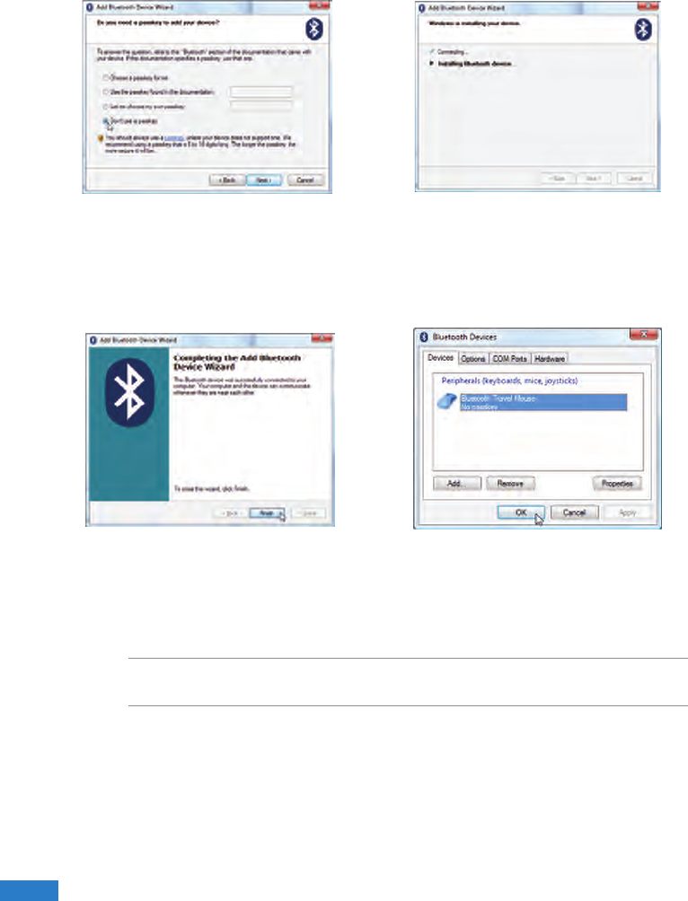
NOTE: “RESET” may be necessary after changing batteries. Repeat steps if
necessary.
6. Select “Don’t use a passkey” and click
Next.
8. Click Finish when adding is complete. 9. You will see your device in the window.
You can also add or remove Bluetooth
devices here.
7. Wait while the Bluetooth mouse is
being added.

47
47
Operating System and Software
This Notebook PC may offer (depending on territory) its customers the choice of a
pre-installed Microsoft Windows operating system. The choices and languages
will depend on the territory. The levels of hardware and software support may vary
depending on the installed operating system. The stability and compatibility of other
operating systems cannot be guaranteed.
Support Software
This Notebook PC comes with a support disc that provides BIOS, drivers and
applications to enable hardware features, extend functionality, help manage your
Notebook PC, or add functionality not provided by the native operating system. If
updates or replacement of the support disc is necessary, contact your dealer for web
sites to download individual software drivers and utilities.
The support disc contains all drivers, utilities and software for all popular operating
systems including those that have been pre-installed. The support disc does not
include the operating system itself. The support disc is necessary even if your
Notebook PC came pre-congured in order to provide additional software not included
as part of the factory pre-install.
A recovery disc is optional and includes an image of the original operating system
installed on the hard drive at the factory. The recovery disc provides a comprehensive
recovery solution that quickly restores the Notebook PC’s operating system to its
original working state provided that your hard disk drive is in good working order.
Contact your retailer if you require such a solution.
NOTE: Some of the Notebook PC’s components and features may not work until the
device drivers and utilities are installed.

48
48
Glossary
ACPI (Advanced Conguration and Power Management Interface)
Modern standard for reducing power usage in computers.
APM (Advanced Power Management)
Modern standard for reducing power usage in computers.
AWG (American Wire Gauge)
NOTE: This table is for general reference only and should not be used as a source of
the American Wire Gauge standard as this table may not be current or complete.
BIOS (Basic Input/Output System)
BIOS is a set of routines that affect how the computer transfers data between
computer components, such as memory, disks, and the display adapter. The BIOS
instructions are built into the computer’s read-only memory. BIOS parameters can be
congured by the user through the BIOS Setup program. The BIOS can be updated
using the provided utility to copy a new BIOS le into the EEPROM.
Bit (Binary Digit)
Represents the smallest unit of data used by the computer. A bit can have one of two values:
0 or 1.
Boot
Boot means to start the computer operating system by loading it into system memory.
When the manual instructs you to “boot” your system (or computer), it means to turn
Gauge Diam Area R I@3A/mm2
AWG (mm) (mm2) (ohm/km) (mA)
33 0.18 0.026 676 75
0.19 0.028 605 85
32 0.20 0.031 547 93
30 0.25 0.049 351 147
29 0.30 0.071 243 212
27 0.35 0.096 178 288
26 0.40 0.13 137 378
25 0.45 0.16 108 477
Gauge Diam Area R I@3A/mm2
AWG (mm) (mm2) (ohm/km) (mA)
24 0.50 0.20 87.5 588
0.55 0.24 72.3 715
0.60 0.28 60.7 850
22 0.65 0.33 51.7 1.0 A
0.70 0.39 44.6 1.16 A
0.75 0.44 38.9 1.32 A
20 0.80 0.50 34.1 1.51 A
0.85 0.57 30.2 1.70 A

49
49
ON your computer. “Reboot” means to restart your computer. When using Windows 95
or later, selecting “Restart” from “Start | Shut Down...” will reboot your computer.
Bluetooth (on selected models)
Bluetooth is a short-range wireless technology that lets you connect computers, mobile
phones, and handheld devices to each other and to the Internet. Bluetooth technology
eliminates the ned for the cables that connect devices together. Bluetooth-enabled
devices connect wirelessly within a 10 m range.
RAM (Random Access Memory)
RAM (usually just called memory) is the place in a computer where the operating
system, application programs, and data in current use are temporarily kept so that they
can be quickly reached by the computer’s processor instead of having to read from and
write to slower storage such as the hard disk or optical disc.
Standby Mode
A power mode that enables a computer to save power consumption while not in use.
When a computer is in Standby Mode, the data on the computer memory is not saved
onto the hard disk. If the power is tuned off, the data in memory will be lost.
Suspend Mode
In Save-to-RAM (STR) and Save-to-Disk (STD), the CPU clock is stopped and most
of the UMPC devices are put in their lowest active state. The UMPC enters Suspend
when the system remains idle for a specied amount of time or manually using the
function keys. The time-out setting of both Hard Disk and Video can be set by the BIOS
Setup. The Power LED blinks when the UMPC is in STR mode. In STD mode, the
UMPC will appear to be powered OFF.
System Disk
A system disk contains the core le of an operating system and is used to boot up the
operating system.

50
50
Twisted-Pair Cable
The cable used to connect the Ethernet card to a host (generally a Hub or Switch) is
called a straight-through Twisted Pair Ethernet (TPE). The end connectors are called
RJ-45 connectors, which are not compatible with RJ-11 telephone connectors. If
connecting two computers together without a hub in between, a crossover twisted-pair
is required.
UltraDMA/66 or 100
UltraDMA/66 or 100 are new specications to improve IDE transfer rates. Unlike
traditional PIO mode, which only uses the rising edge of IDE command signal to
transfer data, UltraDMA/66 or 100 uses both rising edge and falling edge.
USB (Universal Serial Bus)
A new 4-pin serial peripheral bus that allows plug and play computer peripherals such
as keyboard, mouse, joystick, scanner, printer and modem/ISDN to be automatically
congured when they are attached physically without having to install drivers or reboot.
With USB, the traditional complex cables from back panel of your computer can be
eliminated.
Windows
The name of the operating system developed by Microsoft Corporation and used on
this computer.

51
51
Notices
Federal Communications Commission Statement
This device complies with FCC Rules Part 15. Operation is subject to the following two
conditions:
• This device may not cause harmful interference, and
• This device must accept any interference received, including interference that may
cause undesired operation.
This equipment has been tested and found to comply with the limits for a class B digital
device, pursuant to Part 15 of the Federal Communications Commission (FCC) rules.
These limits are designed to provide reasonable protection against harmful interference
in a residential installation. This equipment generates, uses, and can radiate radio
frequency energy and, if not installed and used in accordance with the instructions, may
cause harmful interference to radio communications. However, there is no guarantee
that interference will not occur in a particular installation. If this equipment does cause
harmful interference to radio or television reception, which can be determined by turning
the equipment off and on, the user is encouraged to try to correct the interference by one
or more of the following measures:
• Reorient or relocate the receiving antenna.
• Increase the separation between the equipment and receiver.
• Connect the equipment into an outlet on a circuit different from that to which the
receiver is connected.
• Consult the dealer or an experienced radio/TV technician for help.
WARNING! The use of a shielded-type power cord is required in order to meet
FCC emission limits and to prevent interference to the nearby radio and television
reception. It is essential that only the supplied power cord be used. Use only shielded
cables to connect I/O devices to this equipment. You are cautioned that changes or
modications not expressly approved by the party responsible for compliance could
void your authority to operate the equipment.
(Reprinted from the Code of Federal Regulations #47, part 15.193, 1993. Washington
DC: Ofce of the Federal Register, National Archives and Records Administration, U.S.
Government Printing Ofce.)

52
52
FCC Caution: Any changes or modications not expressly approved by the party
responsible for compliance could void the user’s authority to operate this equipment.
“The manufacture declares that this device is limited to Channels 1 through 11 in the
2.4GHz frequency by specied rmware controlled in the USA.”
Declaration of Conformity (R&TTE directive 1999/5/EC)
The following items were completed and are considered relevant and sufcient:
• Essential requirements as in [Article 3]
• Protection requirements for health and safety as in [Article 3.1a]
• Testing for electric safety according to [EN 60950]
• Protection requirements for electromagnetic compatibility in [Article 3.1b]
• Testing for electromagnetic compatibility in [EN 301 489-1] & [EN 301]
• Testing according to [489-17]
• Effective use of the radio spectrum as in [Article 3.2]
• Radio test suites according to [EN 300 328-2]
FCC RF Radiation Exposure Statement
This equipment complies with FCC RF radiation exposure limits set forth
for an uncontrolled environment. This equipment must not be co-located or
operating in conjunction with any other antenna or transmitter.
FCC RF Radiation Exposure Statement
This equipment complies with FCC RF radiation exposure limits set forth
for an uncontrolled environment. This equipment must not be co-located
or operating in conjunction with any other antenna or transmitter.

53
53
CE Mark Warning
This is a Class B product, in a domestic environment, this product may cause radio
interference, in which case the user may be required to take adequate measures.
IC Radiation Exposure Statement for Canada
This equipment complies with IC radiation exposure limits set forth for an uncontrolled
environment. To maintain compliance with IC RF exposure compliance requirements,
please avoid direct contact to the transmitting antenna during transmitting. End users
must follow the specic operating instructions for satisfying RF exposure compliance.
Operation is subject to the following two conditions:
• This device may not cause interference and
• This device must accept any interference, including interference that may cause
undesired operation of the device.
To prevent radio interference to the licensed service (i.e. co-channel Mobile Satellite
systems) this device is intended to be operated indoors and away from windows
to provide maximum shielding. Equipment (or its transmit antenna) that is installed
outdoors is subject to licensing.
Because high power radars are allocated as primary users (meaning they have priority)
in 5250-5350 MHz, these radars could cause interference and/or damage to license
exempt LAN devices.
Wireless Operation Channel for Different Domains
N. America 2.412-2.462 GHz Ch01 through CH11
Japan 2.412-2.484 GHz Ch01 through Ch14
Europe ETSI 2.412-2.472 GHz Ch01 through Ch13
France Restricted Wireless Frequency Bands
Some areas of France have a restricted frequency band. The worst case maximum
authorized power indoors are:
• 10mW for the entire 2.4 GHz band (2400 MHz–2483.5 MHz)
• 100mW for frequencies between 2446.5 MHz and 2483.5 MHz
NOTE: Channels 10 through 13 inclusive operate in the band 2446.6 MHz to 2483.5 MHz.

54
54
There are few possibilities for outdoor use: On private property or on the private
property of public persons, use is subject to a preliminary authorization procedure by
the Ministry of Defense, with maximum authorized power of 100mW in the 2446.5–
2483.5 MHz band. Use outdoors on public property is not permitted.
In the departments listed below, for the entire 2.4 GHz band:
• Maximum authorized power indoors is 100mW
• Maximum authorized power outdoors is 10mW
Departments in which the use of the 2400–2483.5 MHz band is permitted with an EIRP
of less than 100mW indoors and less than 10mW outdoors:
01 Ain Orientales 02 Aisne 03 Allier
08 Ardennes 09 Ariège 11 Aude
16 Charente 24 Dordogne 25 Doubs
32 Gers 36 Indre 37 Indre et Loire
45 Loiret 50 Manche 55 Meuse
59 Nord 60 Oise 61 Orne
64 Pyrénées Atlantique 66 Pyrénées 67 Bas Rhin
70 Haute Saône 71 Saône et Loire 75 Paris
84 Vaucluse 88 Vosges 89 Yonne
94 Val de Marne 41 Loir et Cher 82 Tarn et Garonne
05 Hautes Alpes 58 Nièvre 90 Territoire de Belfort
12 Aveyron 63 Puy du Dôme
26 Drôme 68 Haut Rhin
This requirement is likely to change over time, allowing you to use your wireless LAN
card in more areas within France. Please check with ART for the latest information
(www.art-telecom.fr)
NOTE: Your WLAN Card transmits less than 100mW, but more than 10mW.

55
55
UL Safety Notices
Required for UL 1459 covering telecommunications (telephone) equipment intended to
be electrically connected to a telecommunication network that has an operating voltage
to ground that does not exceed 200V peak, 300V peak-to-peak, and 105V rms, and
installed or used in accordance with the National Electrical Code (NFPA 70).
When using the UMPC modem, basic safety precautions should always be followed to
reduce the risk of re, electric shock, and injury to persons, including the following:
• Do not use the UMPC near water, for example, near a bath tub, wash bowl, kitchen
sink or laundry tub, in a wet basement or near a swimming pool.
• Do not use the UMPC during an electrical storm. There may be a remote risk of
electric shock from lightning.
• Do not use the UMPC in the vicinity of a gas leak.
Required for UL 1642 covering primary (non-rechargeable) and secondary
(rechargeable) lithium batteries for use as power sources in products. These batteries
contain metallic lithium, or a lithium alloy, or a lithium ion, and may consist of a single
electrochemical cell or two or more cells connected in series, parallel, or both, that
convert chemical energy into electrical energy by an irreversible or reversible chemical
reaction.
• Do not dispose the UMPC battery pack in a re, as they may explode. Check with
local codes for possible special disposal instructions to reduce the risk of injury to
persons due to re or explosion.
• Do not use power adapters or batteries from other devices to reduce the risk of
injury to persons due to re or explosion. Use only UL certied power adapters or
batteries supplied by the manufacturer or authorized retailers.
Power Safety Requirement
Products with electrical current ratings up to 6A and weighing more than 3Kg must use
approved power cords greater than or equal to: H05VV-F, 3G, 0.75mm2 or H05VV-F,
2G, 0.75mm2.

56
56
Nordic Lithium Cautions (for lithium-ion batteries)
CAUTION! Danger of explosion if battery is incorrectly replaced. Replace only with the
same or equivalent type recommended by the manufacturer. Dispose of used batteries
according to the manufacturer’s instructions. (English)
ATTENZIONE! Rischio di esplosione della batteria se sostituita in modo errato.
Sostituire la batteria con un una di tipo uguale o equivalente consigliata dalla fabbrica.
Non disperdere le batterie nell’ambiente. (Italian)
VORSICHT! Explosionsgetahr bei unsachgemäßen Austausch der Batterie. Ersatz nur
durch denselben oder einem vom Hersteller empfohlenem ähnlichen Typ. Entsorgung
gebrauchter Batterien nach Angaben des Herstellers. (German)
ADVARSELI! Lithiumbatteri - Eksplosionsfare ved fejlagtig håndtering. Udskiftning
må kun ske med batteri af samme fabrikat og type. Levér det brugte batteri tilbage til
leverandøren. (Danish)
VARNING! Explosionsfara vid felaktigt batteribyte. Använd samma batterityp eller en
ekvivalent typ som rekommenderas av apparattillverkaren. Kassera använt batteri enligt
fabrikantens instruktion. (Swedish)
VAROITUS! Paristo voi räjähtää, jos se on virheellisesti asennettu. Vaihda paristo
ainoastaan laitevalmistajan sousittelemaan tyyppiin. Hävitä käytetty paristo valmistagan
ohjeiden mukaisesti. (Finnish)
ATTENTION! Il y a danger d’explosion s’il y a remplacement incorrect de la batterie.
Remplacer uniquement avec une batterie du mêre type ou d’un type équivalent
recommandé par le constructeur. Mettre au rebut les batteries usagées conformément
aux instructions du fabricant. (French)
ADVARSEL! Eksplosjonsfare ved feilaktig skifte av batteri. Benytt samme batteritype
eller en tilsvarende type anbefalt av apparatfabrikanten. Brukte batterier kasseres i
henhold til fabrikantens instruksjoner. (Norwegian)
(Japanese)

57
57
ASUS Contact information
ASUSTeK COMPUTER INC. (AsiaPacic)
Address 15 Li-Te Road, Peitou, Taipei, Taiwan 11259
Website www.asus.com.tw
Technical Support
Telephone +886228943447
Support Fax +886228907698
Software download support.asus.com*
ASUS COMPUTER INTERNATIONAL (America)
Address 44370 Nobel Drive, Fremont, CA 94538, USA
Telephone +15029550883
Fax +15029338713
Website usa.asus.com
Software download support.asus.com*
ASUS COMPUTER GmbH (Germany and Austria)
Address Harkort Str. 25, D40880 Ratingen, Germany
Telephone +49210295990
Fax +492102959911
Online contact www.asus.com.de/sales
Technical Support
Telephone +49210295990
Fax +492102959911
Online support www.asus.com.de/support
Website www.asus.com.de/news
* Available on this site is an online Technical Inquiry Form that you can ll out to contact technical
support.

58
58