ASUSTeK Computer R50AWI22 ULTRA MOBILE PC User Manual USERS MANUAL 2
ASUSTeK Computer Inc ULTRA MOBILE PC USERS MANUAL 2
UserManual.wiki
>
ASUSTeK Computer
>
R50AWI22 User Manual
>
USERS MANUAL 2
Contents
1.
USERS MANUAL 1
2.
USERS MANUAL 2
USERS MANUAL 2
Navigation menu
Upload a User Manual
Namespaces
Wiki Guide
HTML
PDF
Info
Views
User Manual
Discussion / Help
Navigation
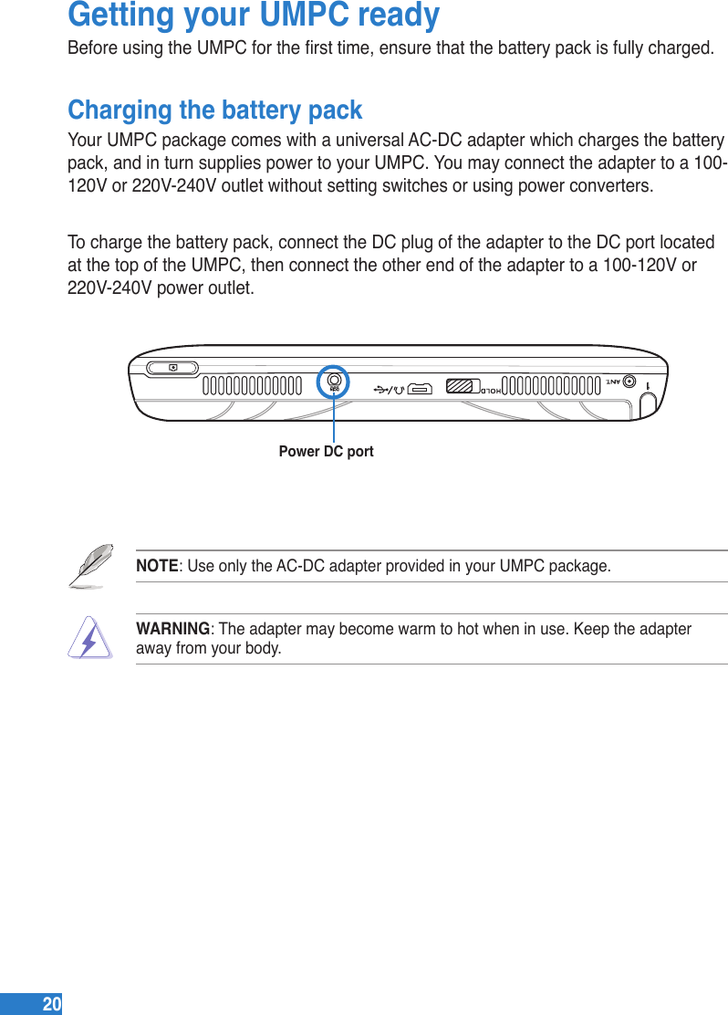
![2222Starting upPowering on your UMPCLike a regular desktop PC, your UMPC automatically runs a series of diagnostic tests called Power-On Self Test (POST) upon turning it on. After POST is completed, your UMPC boots up, then its Windows® operating system starts automatically.To power on your UMPC:1. Locate the power switch at the left side of your UMPC.2. Press the switch down to turn on the UMPC. The UMPC boots up, then the operating system starts automatically.3. Use your UMPC as you would use a regular desktop PC.Power switchNOTES: • If your UMPC does not turn on, check if the Hold key is in Hold (red) mode or if the battery pack is charged. • To set or modify the system conguration, press [F2] upon boot up to enter the BIOS setup.Conserving powerYour UMPC is equipped with power saving features which helps conserve power and maximizes your UMPC’s performance.Selecting a power planOne of these power saving features is the power plan which is a collection of advanced power management settings.To select a power plan:1. From your UMPC screen, go to Start > Control Panel > Mobile PC > Change battery settings.2. Select or customize a power plan from the list of existing power plans.](https://usermanual.wiki/ASUSTeK-Computer/R50AWI22.USERS-MANUAL-2/User-Guide-975079-Page-6.png)

![34341. Press [WIRELESS] switch repeatedly until Wireless LAN ON or WLAN & Bluetooth ON is shown.Windows Wireless Network ConnectionConnecting to a network (Vista)2. You should see the “Not Connected” network icon.4. Select “Show Wireless” if you have many networks in your area.5. Select the wireless network you want to connect to.6. When connecting, you may have to enter a password.7. After connection has been established, “Connected” will be shown.1b. Or double click the Wireless Console icon on the taskbar and select either the 1st icon to activate both Wireless & Bluetooth, or select the 2nd icon for Wireless activation only.3. Right click on the WLAN icon and select Connect to a network.](https://usermanual.wiki/ASUSTeK-Computer/R50AWI22.USERS-MANUAL-2/User-Guide-975079-Page-18.png)
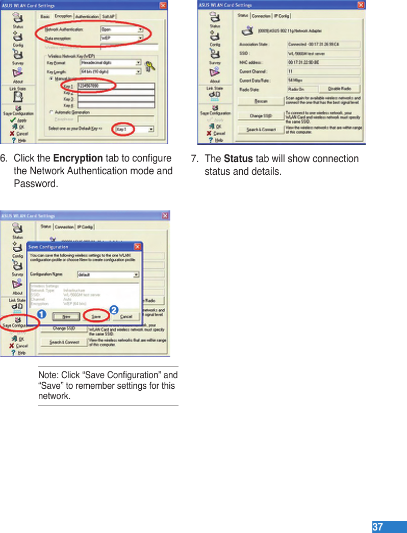
![3535Connecting to a network (XP)Using Windows XP wireless settings require that you select this option in the ASUS WLAN Control Center. 1. Press [WIRELESS] switch repeatedly until Wireless LAN ON or WLAN & Bluetooth ON is shown. 2. Double click the WLAN icon on the taskbar.3. Select Refresh network list from the left side menu and a list of available network within your area and its signal strength will show. Select your network and click on Connect.4. When connecting, you may have to enter a password.5. After connection has been established, “Connected” will be shown on the right side above the signal strength indicator.1b. Or double click the Wireless Console icon on the taskbar and click on the 1st icon to activate both Wireless & Bluetooth, or select the 2nd icon for Wireless activation only.](https://usermanual.wiki/ASUSTeK-Computer/R50AWI22.USERS-MANUAL-2/User-Guide-975079-Page-19.png)
![3636ASUS Wireless LAN (on selected models)Connecting to a network Using ASUS wireless settings require that you select this option in the ASUS WLAN Control Center.2. Double click the icon on the desktop or click Start | Programs | ASUS Utility | WLAN Card | ASUS WLAN Control Center.3. On the left hand side menu, click Survey to start scanning for available networks in your area.4. The list will show all available networks within your area. Select the network you want and click Connect.5. If the selected Network has security settings, you may be required to enter a password. 1. Press [WIRELESS] switch repeatedly until Wireless LAN ON or WLAN & Bluetooth ON is shown. 1b. Or double click the Wireless Console icon on the taskbar and click on the 1st icon to activate both Wireless & Bluetooth, or select the 2nd icon for Wireless activation only.](https://usermanual.wiki/ASUSTeK-Computer/R50AWI22.USERS-MANUAL-2/User-Guide-975079-Page-20.png)
![3838Bluetooth Wireless Connection (on selected models)Notebook PCs with Bluetooth technology eliminates the need for cables for connecting Bluetooth-enabled devices. Examples of Bluetooth-enabled devices may be Notebook PCs, Desktop PCs, mobile phones, and PDAs. Note: If your Notebook PC did not come with built-in Bluetooth, you need to connect a USB or ExpressCard Bluetooth module in order to use Bluetooth. Bluetooth-enabled mobile phonesYou can wireless connect to your mobile phone. Depending on your mobile phone’s capabilities, you can transfer phone book data, photos, sound les, etc. or use it as a modem to connect to the Internet. You may also use it for SMS messaging. Bluetooth-enabled computers or PDAsYou can wireless connect to another computer or PDA and exchange les, share peripherals, or share Internet or network connections. You may also make use of Bluetooth-enabled wireless keyboard or mouse.Turning ON and Launching Bluetooth Utility (Vista)This process can be used to add most Bluetooth devices. See Appendix for complete process.1. Press [WIRELESS] switch repeatedly until Bluetooth ON or WLAN & Bluetooth ON is shown.1b. Or double click the Wireless Console icon on the taskbar and select either the 1st icon to activate both Wireless & Bluetooth, or select the 3rd icon for Bluetooth activation only.](https://usermanual.wiki/ASUSTeK-Computer/R50AWI22.USERS-MANUAL-2/User-Guide-975079-Page-22.png)
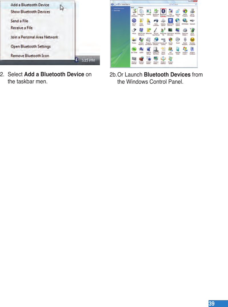

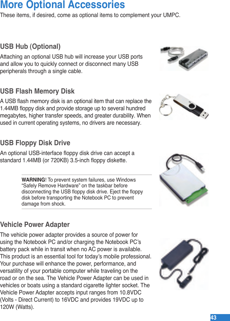
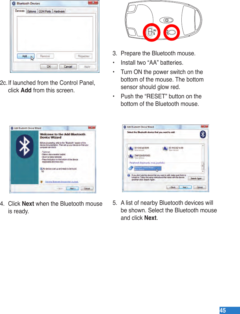
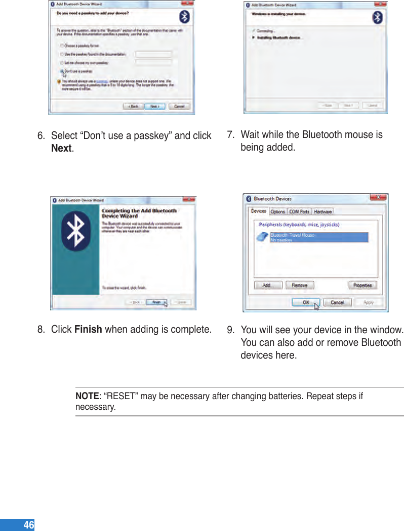
![4444Optional ConnectionsThese items, if desired, may be purchased from third-parties.Printer Connection One or more USB printers can be simultaneously used on any USB port or USB hub.Bluetooth Mouse Setup (optional)This process can be used to add most Bluetooth devices in Windows operating system.2. Select Add a Bluetooth Device on the taskbar menu.2b. Or Launch Bluetooth Devices from the Windows Control Panel.1. Press [WIRELESS] switch repeatedly until Bluetooth ON or WLAN & Bluetooth ON is shown.1b. Or double click the Wireless Console icon on the taskbar and select either the 1st icon to activate both Wireless & Bluetooth, or select the 3rd icon for Bluetooth activation only.](https://usermanual.wiki/ASUSTeK-Computer/R50AWI22.USERS-MANUAL-2/User-Guide-975079-Page-28.png)
![5252 FCC Caution: Any changes or modications not expressly approved by the party responsible for compliance could void the user’s authority to operate this equipment. “The manufacture declares that this device is limited to Channels 1 through 11 in the 2.4GHz frequency by specied rmware controlled in the USA.”Declaration of Conformity (R&TTE directive 1999/5/EC)The following items were completed and are considered relevant and sufcient:• Essential requirements as in [Article 3]• Protection requirements for health and safety as in [Article 3.1a]• Testing for electric safety according to [EN 60950]• Protection requirements for electromagnetic compatibility in [Article 3.1b]• Testing for electromagnetic compatibility in [EN 301 489-1] & [EN 301]• Testing according to [489-17]• Effective use of the radio spectrum as in [Article 3.2]• Radio test suites according to [EN 300 328-2]FCC RF Radiation Exposure Statement This equipment complies with FCC RF radiation exposure limits set forth for an uncontrolled environment. This equipment must not be co-located or operating in conjunction with any other antenna or transmitter. FCC RF Radiation Exposure StatementThis equipment complies with FCC RF radiation exposure limits set forth for an uncontrolled environment. This equipment must not be co-located or operating in conjunction with any other antenna or transmitter.](https://usermanual.wiki/ASUSTeK-Computer/R50AWI22.USERS-MANUAL-2/User-Guide-975079-Page-36.png)