ATrack Technology ATVT1302 CDMA OBD VEHICLE TRACKER User Manual
ATrack Technology Inc. CDMA OBD VEHICLE TRACKER
User Manual

AX7
User Manual
Revision: 03
Revision Date: 2012/06/25
ATrack Technology Inc.
3F., No. 88, Sec. 1, Neihu Rd., Neihu Dist.,
Taipei City 11493, Taiwan (R.O.C.)
Tel: +886-2-27975852
Fax: +886-2-27974030
http://www.atrack.com.tw

Confidential Document
© ATrack Technology Inc. All Rights Reserved. Page 2 of 21
Contents
1.Notification .............................................................................................................................. 3
1.1.Disclaimer .................................................................................................................................... 3
1.2.Copyright ...................................................................................................................................... 3
1.3.Warning ........................................................................................................................................ 3
2.Introduction ............................................................................................................................. 4
2.1.Package Content ......................................................................................................................... 4
2.2.AX7 OBD-II Compliant ................................................................................................................. 4
3.Hardware Features ................................................................................................................. 5
3.1.OBD-II Protocol ............................................................................................................................ 5
3.2.Micro USB Connection ................................................................................................................. 5
3.3.Buzzer Operation ......................................................................................................................... 5
3.4.Power Supply ............................................................................................................................... 5
3.5.Wireless Relay ............................................................................................................................. 6
3.6.LED Indication .............................................................................................................................. 6
4.Configration ............................................................................................................................ 7
4.1.USB Driver Installation ................................................................................................................. 7
4.2.Configure the AX7 device .......................................................................................................... 10
4.3.Firmware Upgrade ..................................................................................................................... 14
5.Installation ............................................................................................................................. 16
5.1.What is the OBD-II DLC Connector ........................................................................................... 16
5.2.Using Low Profile OBD-II Extension Cable ................................................................................ 17
5.3.GPS Performance for Installation .............................................................................................. 18
5.4.Simple Verification for Installation .............................................................................................. 19
6.Appendix ................................................................................................................................ 20
6.1.Hardware Specification .............................................................................................................. 20
6.2.FCC Regulations: ....................................................................................................................... 21

Confidential Document
© ATrack Technology Inc. All Rights Reserved. Page 3 of 21
1
1.
.
N
No
ot
ti
if
fi
ic
ca
at
ti
io
on
n
1
1.
.1
1.
.
D
Di
is
sc
cl
la
ai
im
me
er
r
This document, and all other related products, such as device, firmware, and software, is developed by
ATrack Technology Inc. thoroughly. At the time of release, it is most compatible with specified firmware version.
Due to the functionalities of the devices are being developed and improved from time to time, the change in
the protocol, specification, and firmware functions are subjects to change without notice. ATrack Technology
Inc. is obligated to modify all the documentation without the limitation of time frame. A change notice shall be
released to ATrack Technology Inc. customers upon the completion of document modification.
ATrack Technology Inc. products are not intended to be used as life support or rescue equipments. ATrack
Technology Inc. is not liable for any loss or injury caused by using or referencing to any products. Any possible
means of using or integrating ATrack Technology Inc. products shall be avoided.
1
1.
.2
2.
.
C
Co
op
py
yr
ri
ig
gh
ht
t
ATrack Technology Inc. holds all parts of intellectual rights applicable in the copyright laws in all the countries.
Any or all parts of this document shall not be exposed to non-authorized party without any form of approval
from ATrack Technology Inc. Any forms, including but not limited to oral, copy, or internet sharing, of releasing
or exposing information to an unauthorized party shall be prohibited. ATrack Technology Inc. reserves the
rights of litigation in the violation of such copyright laws.
1
1.
.3
3.
.
W
Wa
ar
rn
ni
in
ng
g
Connecting the wire inputs can be hazardous to both the installer and your vehicle’s electrical system if not
done by an experienced installer. This document assumes you are aware of the inherent dangers of working
in and around a vehicle and have a working understanding of electricity.
Confidential Document
© ATrack Technology Inc. All Rights Reserved. Page 4 of 21
2
2.
.
I
In
nt
tr
ro
od
du
uc
ct
ti
io
on
n
AX7 GPS Tracking Device is the most advanced and economical diagnostic device for communicating vehicle
information to the CDMA networks. With integrated high sensitive GPS receiver, the AX7 provides the
fundamental functions with optional advance features for tracing light trucks and passenger vehicles in need
of monitoring location, speed, and many other codes available on the OBD port of vehicles.
2
2.
.1
1.
.
P
Pa
ac
ck
ka
ag
ge
e
C
Co
on
nt
te
en
nt
t
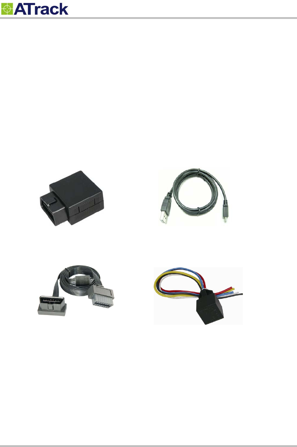
Each package contains the following standard device/accessories:
AX7 Device * 1
USB Cable * 1
Optional accessories:
Low Profile OBD-II Extension Cable
Wireless Relay
2
2.
.2
2.
.
A
AX
X7
7
O
OB
BD
D-
-I
II
I
C
Co
om
mp
pl
li
ia
an
nt
t
OBD-II is a standard that issued by SAE (Society of Automotive Engineers) in the early 1990s. But some
vehicles are not following this standard. Therefore ATrack cannot guarantee the OBD-II performance of the
AX7 with every vehicle. For more information about AX7 OBD-II compliance, please refer to “ATrack AX7
OBD-II Compliant Guide” document.

Confidential Document
© ATrack Technology Inc. All Rights Reserved. Page 5 of 21
3
3.
.
H
Ha
ar
rd
dw
wa
ar
re
e
F
Fe
ea
at
tu
ur
re
es
s
3
3.
.1
1.
.
O
OB
BD
D-
-I
II
I
P
Pr
ro
ot
to
oc
co
ol
l
There are five signaling protocols that are permitted with the OBD-II interface. Most vehicles have been
implemented with only one of the protocols. The AX7 features a superior protocol detection algorithm that
ensures the device connects reliably even to vehicles that do not fully conform to the OBDII standards. The
AX7 supported all legislated OBD-II protocols below:
J1850 PWM (Ford vehicles)
J1850 VPW (GM vehicles)
ISO9141-2 (Asian, European, Chrysler vehicles)
ISO 14230-4 KWP
ISO 15765-4 CAN (11/29 bit ID,250/500 Kbaud)
The AXTool has an “OBD Live Data” viewer for showing OBD data in real time. See Section 4.2 for detail
descriptions.
3
3.
.2
2.
.
M
Mi
ic
cr
ro
o
U
US
SB
B
C
Co
on
nn
ne
ec
ct
ti
io
on
n
The Micro USB can supply power to the AX7 device for parameters setting or firmware upgrade purpose.
When micro USB is connected to your laptop/PC and main power is not applied, the OBD-II and CDMA
functions will be turned off temporarily.
3
3.
.3
3.
.
B
Bu
uz
zz
ze
er
r
O
Op
pe
er
ra
at
ti
io
on
n
The internal buzzer of the AX7 can be configured by any events or triggered by remote CDMA server. Refer to
AX7 Protocol Document for details.
3
3.
.4
4.
.
P
Po
ow
we
er
r
S
Su
up
pp
pl
ly
y
The AX7 device connects to the OBD-II SAE J1962 connector of vehicle and draws power from the OBD port.
No additional power cabling is required for operation. If the OBD port of vehicle is covered or you need to
install AX7 in another place for better GPS reception, the optional low profile OBD-II extension cable is
required.
Confidential Document
© ATrack Technology Inc. All Rights Reserved. Page 6 of 21
3
3.
.5
5.
.
W
Wi
ir
re
el
le
es
ss
s
R
Re
el
la
ay
y
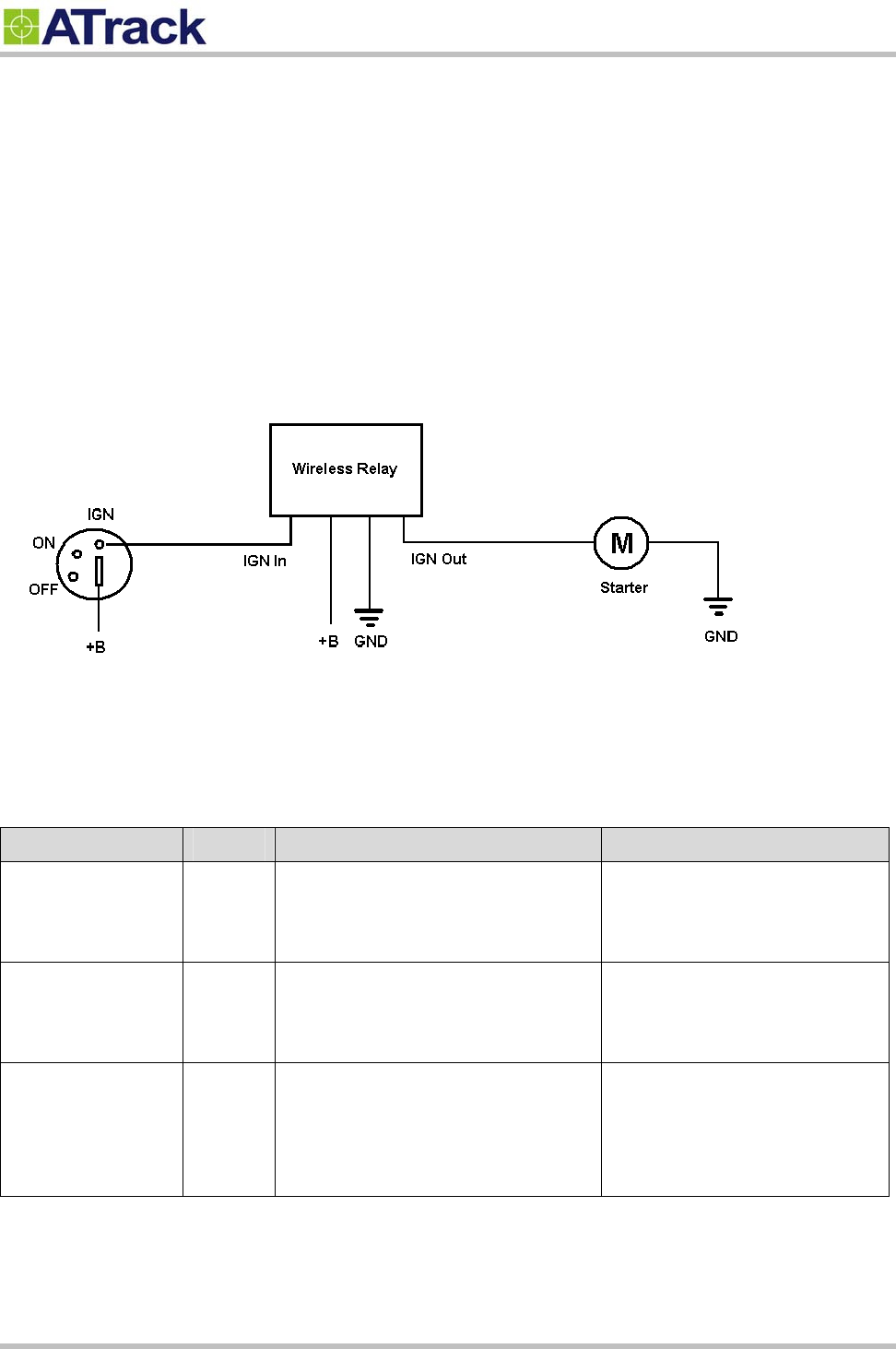
The optional wireless relay is used for immobilizing vehicle when AX7 device is unplugged. Using the short
range RF technology, the Wireless Relay will keep receiving RF data from AX7. Once the Wireless Relay
loses connection from AX7 for 30 seconds, the Wireless Relay will be switched off. For safety reasons it is
recommended to connect the Wireless Relay to control the starter of vehicle. Do NOT use the Wireless Relay
to control fuel pump or power train of vehicle. See the following diagram for the wiring connection of Wireless
Relay.
3
3.
.6
6.
.
L
LE
ED
D
I
In
nd
di
ic
ca
at
ti
io
on
n
The following table describes the LED operation of AX7:
LED Indicators Color LED Status Description
OBD Green Solid OFF
Fast blinking
Blinking every 10 seconds
OBD Protocol not found
OBD-II data transmission.
Deep sleep mode
GPS Blue Solid OFF
Blinking every 1 second
Solid ON
GPS power OFF
GPS not fix
GPS Location Fix
CDMA Red Solid OFF
Blinking every 1 second
Blinking every 2 second
CDMA Power OFF
CDMA no signal
CDMA registered
Confidential Document
© ATrack Technology Inc. All Rights Reserved. Page 7 of 21
4
4.
.
C
Co
on
nf
fi
ig
gr
ra
at
ti
io
on
n
4
4.
.1
1.
.
U
US
SB
B
D
Dr
ri
iv
ve
er
r
I
In
ns
st
ta
al
ll
la
at
ti
io
on
n
These instructions illustrate how to correctly install the USB driver in Windows platform. The procedure will
vary for other Windows-based Operating Systems.
1. Connect the Device to the USB port on a Windows-based computer.
2. Install the USB driver.
Connect the device to a USB Port
Supported Operating Systems including Windows 2000, Windows XP, Windows 7 and Windows Vista. When
you connect the device to the computer, you will be prompted to install the driver.
Follow the steps in the next section to install the driver.
Install the USB Driver
The AX7 USB Driver can be requested from ATrack support via email or from the Partner Login section of the
ATrack website at www.atrack.com.tw.
After connecting the device to the computer, follow these steps to complete the installation of the USB driver:
There might be multiple steps to installing the USB driver. Once each step is completed, the next step will
automatically begin itself.
The following screen captures may reflect a different device driver than the one you are installing; however,
the steps in the procedure will remain the same.
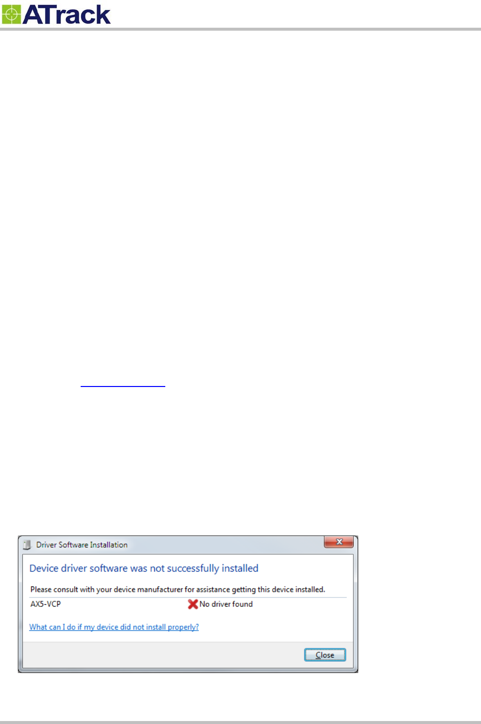
1. The Windows Operating System will detect the new USB device.
2. You will see the following screen for no driver found:
Confidential Document
© ATrack Technology Inc. All Rights Reserved. Page 8 of 21
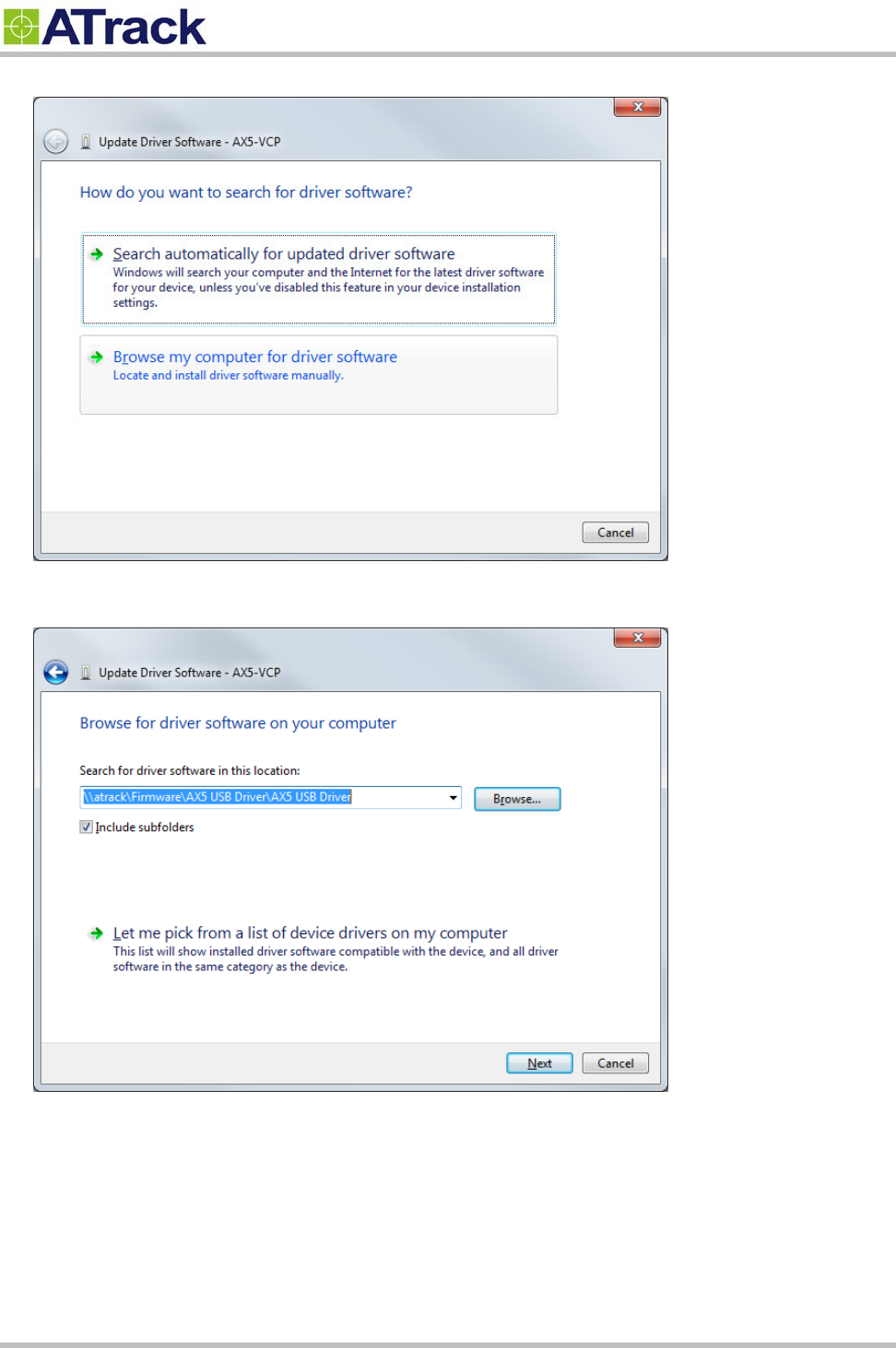
3. To install the driver, click on "Browse my computer for driver software"
4. Click on "Browse" button, and go to the driver provided/downloaded from ATrack.
Confidential Document
© ATrack Technology Inc. All Rights Reserved. Page 9 of 21
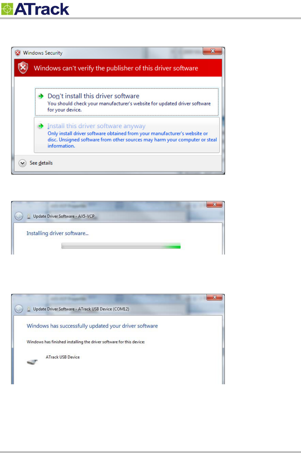
5. Windows might give a warning about the verification fail. Please click on "Install this driver software
anyway" to proceed.
6. You should be able to see a progress bar running.
7. Once the installation is completed, you should be able to see the COM port showing. This will be the COM
port you use for communicate with the AX7 when USB is plugged in.
Confidential Document
© ATrack Technology Inc. All Rights Reserved. Page 10 of 21
4
4.
.2
2.
.
C
Co
on
nf
fi
ig
gu
ur
re
e
t
th
he
e
A
AX
X7
7
d
de
ev
vi
ic
ce
e
The AXTool is a simple configuration tool for the AX7 device. It is useful for user to setting basic parameters
into the AX7 device. For advanced users, please refer to the ATrack A-Series Protocol Document for detail
descriptions.
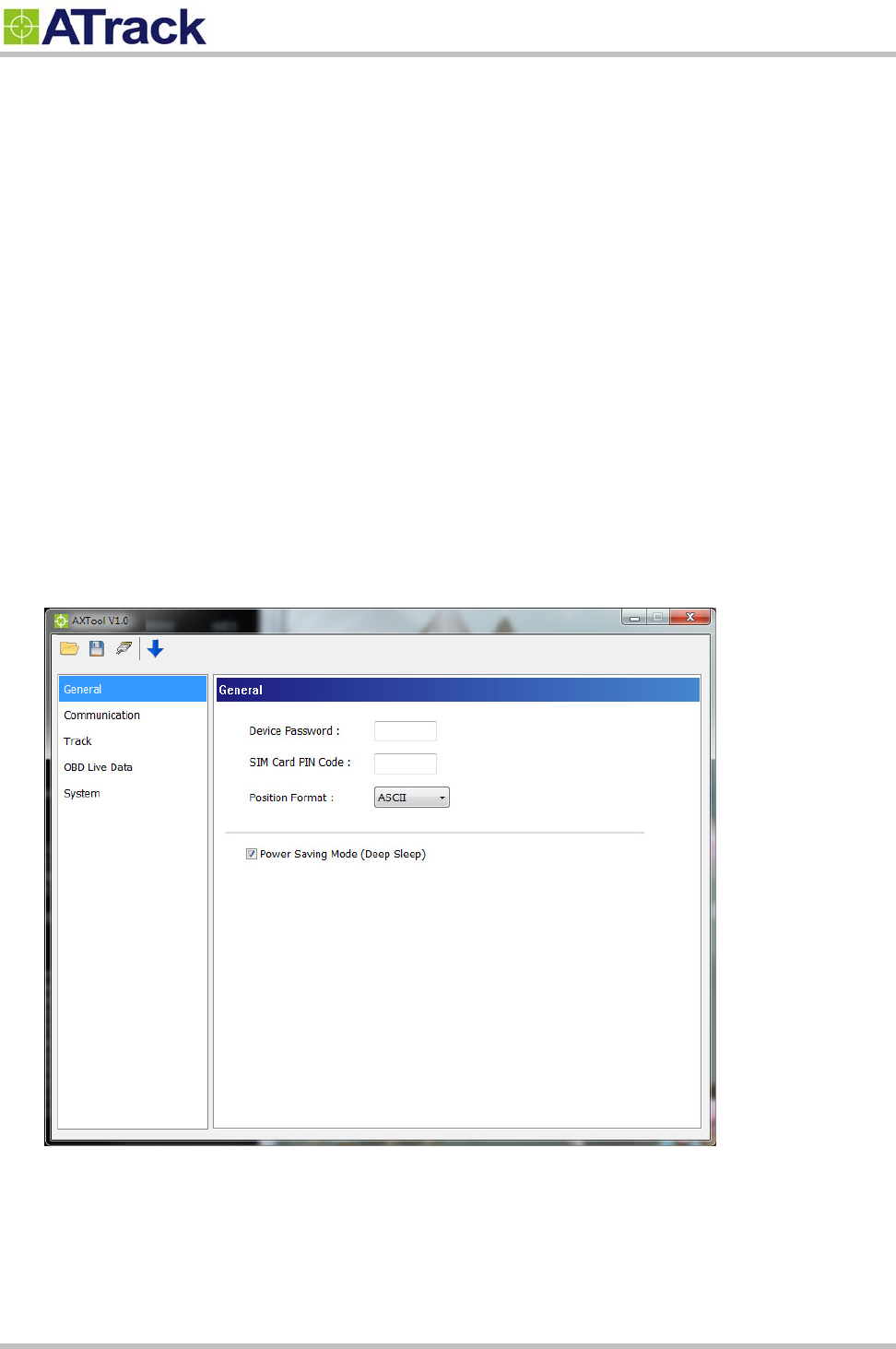
General Setting
[Device Password]: The device password is used for protecting device configurations. The maximum
length is 6 characters.
[SIM Card PIN Code]: Enter PIN code of SIM card correctly for register to network property if enabled.
[Position Format]: Select position format for all reports.
[Power Saving Mode]: Enable/Disable power saving mode. When power saving mode is enabled, the
AX7 device will go into deep sleep mode after 1 minute of engine off.
Confidential Document
© ATrack Technology Inc. All Rights Reserved. Page 11 of 21
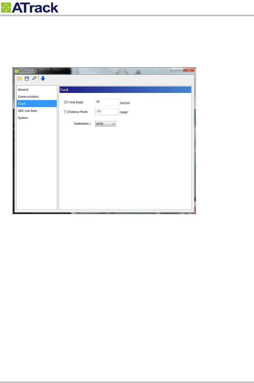
Track Setting
Setting tracking interval when vehicle engine is ON.
When [Time Mode] and [Distance Mode] are both selected, the tracking behavior will operate in AND
condition.
Confidential Document
© ATrack Technology Inc. All Rights Reserved. Page 12 of 21
OBD Live Data
When AX7 has connected to the OBD-II port of the vehicle. The [OBD Live Data] will showing the OBD
live data from OBD-II port. This viewer could help to know which OBD data can be acquired by AX7
device.
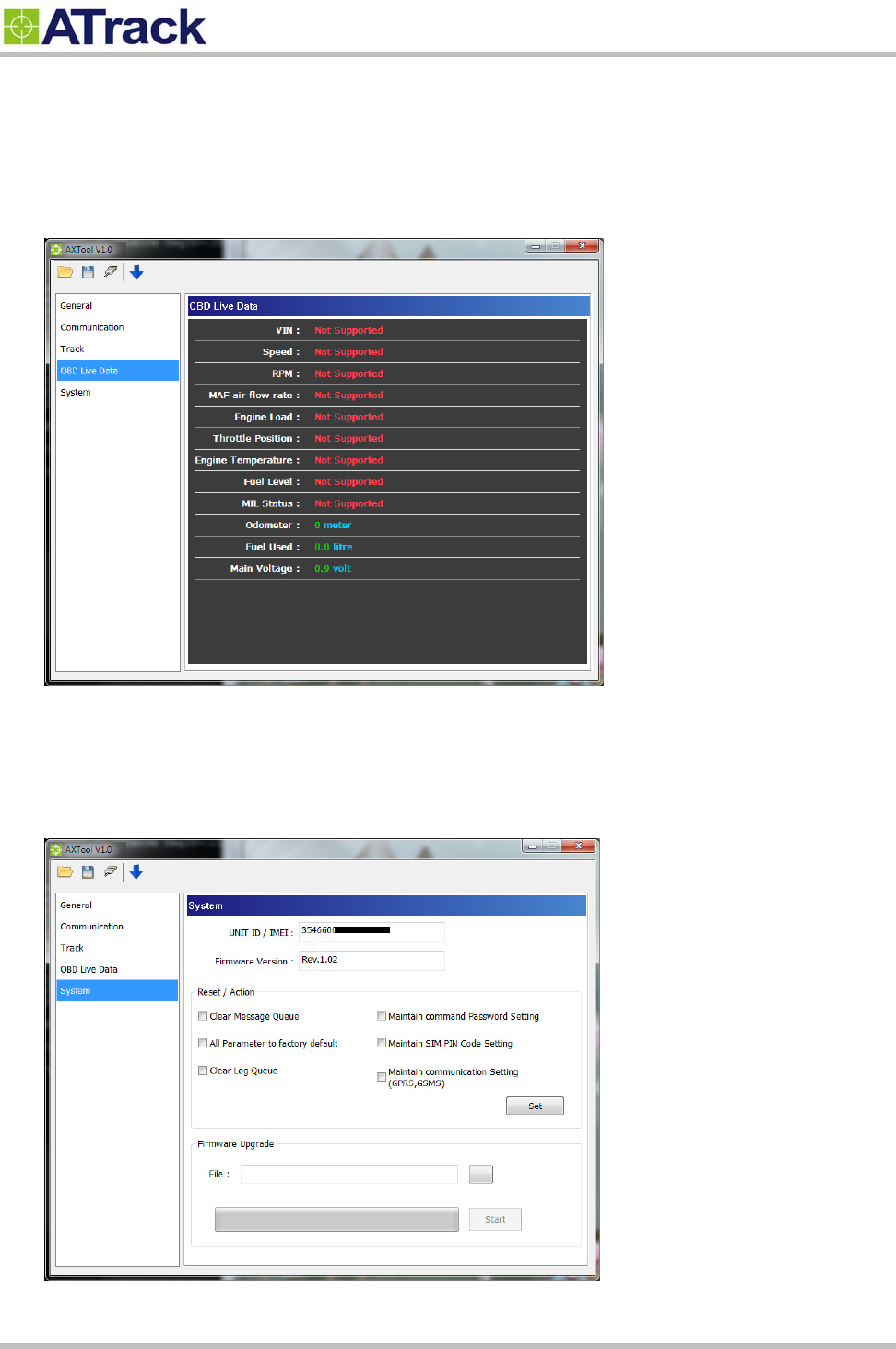
System Setting
The [System] setting will showing current connected AX7 device information. The [Reset/Action] function
can be used to reset parameters or clear buffered messages in the AX7 device.
Confidential Document
© ATrack Technology Inc. All Rights Reserved. Page 13 of 21
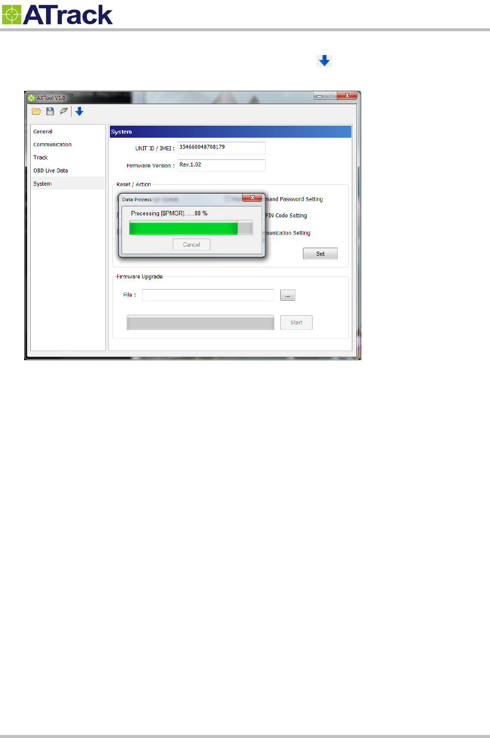
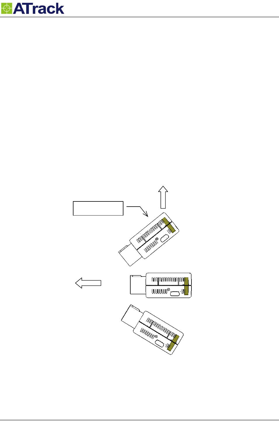
Uploading Setting To Device
Once all the settings are entered, use the Blue Downward Arrow ( ) to upload the settings to the
device. A popup window will show the progress. When it finishes, the popup window will close.
Confidential Document
© ATrack Technology Inc. All Rights Reserved. Page 14 of 21
4
4.
.3
3.
.
F
Fi
ir
rm
mw
wa
ar
re
e
U
Up
pg
gr
ra
ad
de
e
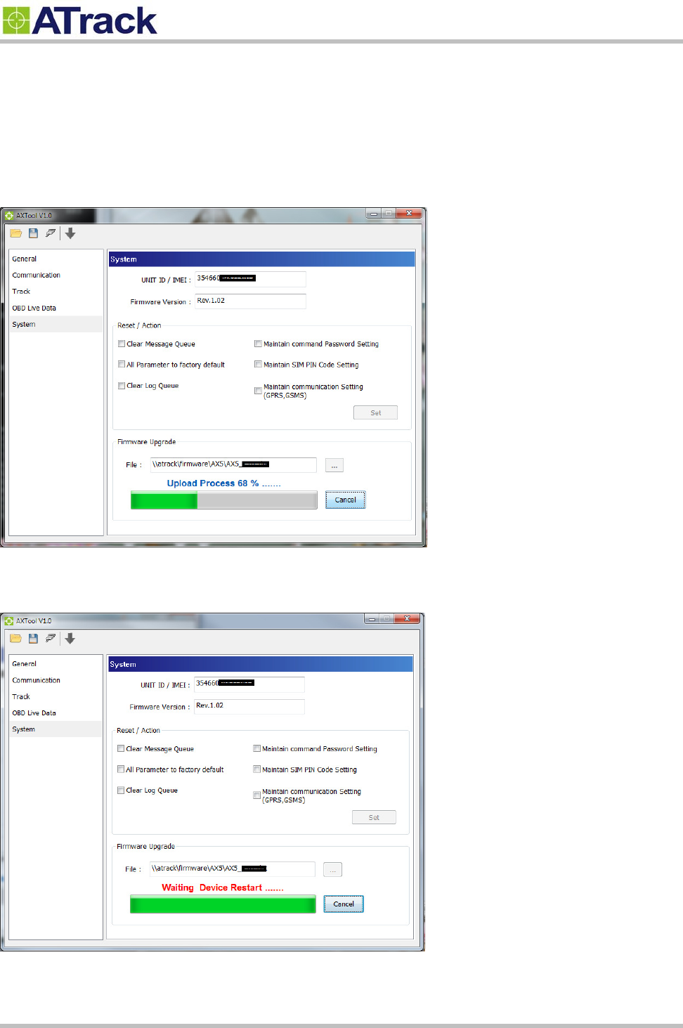
Open AXTool program and click [System] item of the manu.
Select firmware file which is provided by ATrack and click [Start] button.
When “Waiting Device Restart…” message is prompted, please do not turn off the device.
Confidential Document
© ATrack Technology Inc. All Rights Reserved. Page 15 of 21
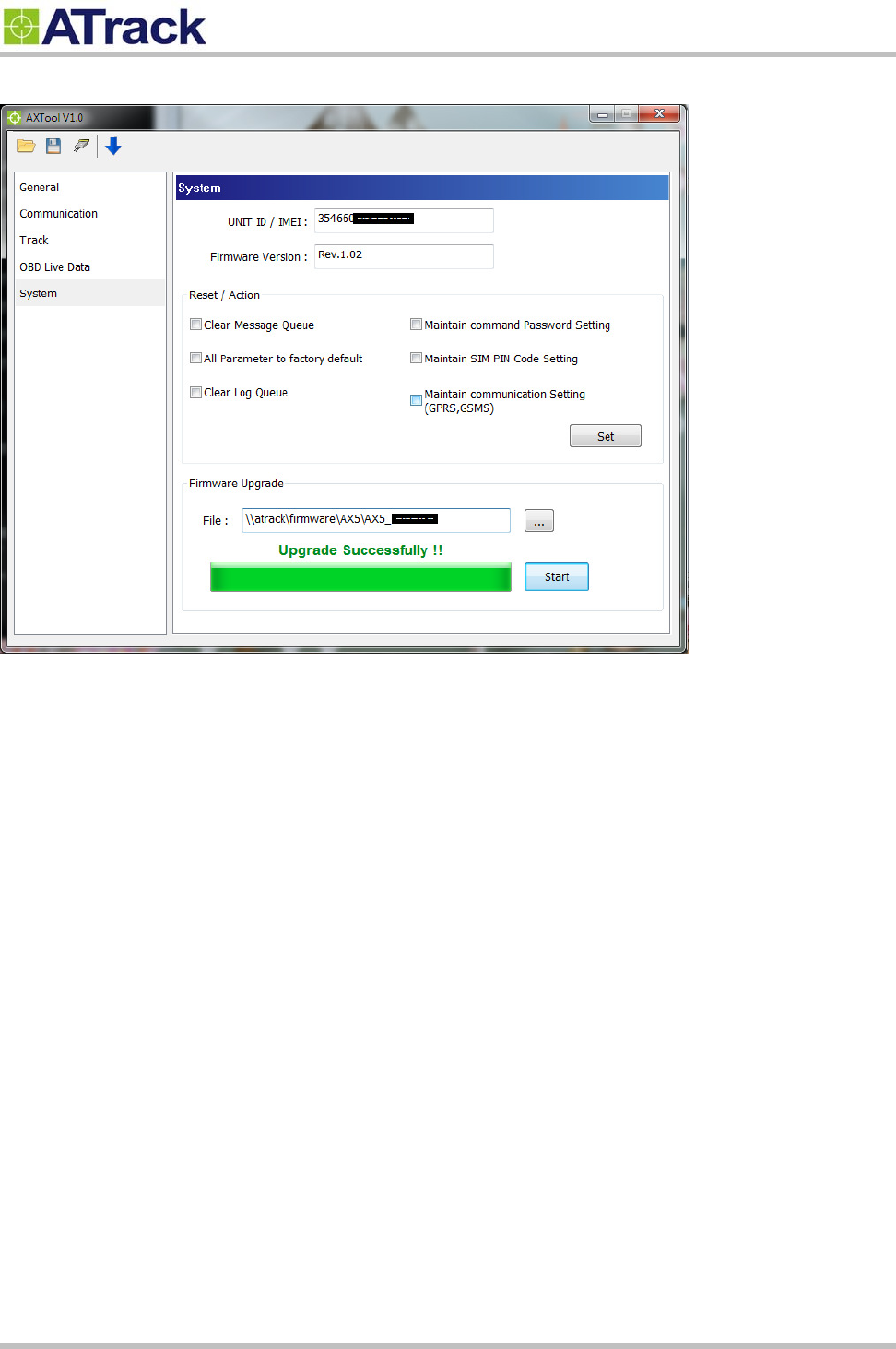
When “Upgrade Successfully !!” message is prompted, that means the device firmware is upgraded.
Confidential Document
© ATrack Technology Inc. All Rights Reserved. Page 16 of 21
5
5.
.
I
In
ns
st
ta
al
ll
la
at
ti
io
on
n
AX7 is a new design for easy installation. Just find the DLC connector of your vehicle and plug AX7 to the
port.
5
5.
.1
1.
.
W
Wh
ha
at
t
i
is
s
t
th
he
e
O
OB
BD
D-
-I
II
I
D
DL
LC
C
C
Co
on
nn
ne
ec
ct
to
or
r
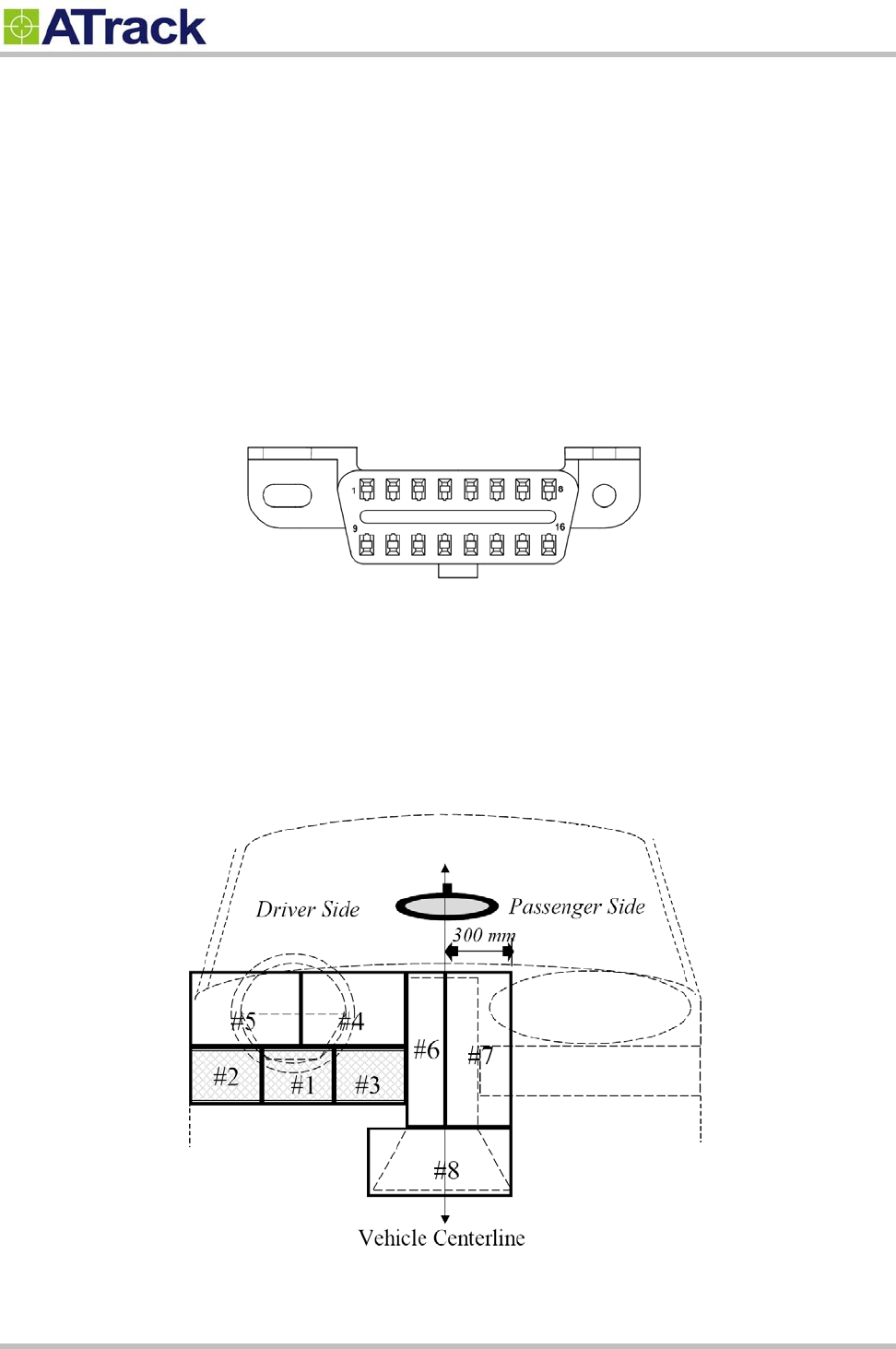
The OBD-II DLC connector is a standard connector for all vehicles which OBD-II compliant. The OBD-II DLC
connector is shown below:
The OBD-II DLC connector shall be located in the passenger or driver’s compartment in the area bounded by
the driver's end of the instrument panel to 300 mm beyond the vehicle centerline. See the following figure for
DLC location for most of vehicle. Location #1~#3 is under the dashboard of the driver side. Location #4~#5 is
on the dashboard instrument/gauge area. Location #6~#7 is near radio and climate controller. Location #8 is
near armrest and handbrake area.
Confidential Document
© ATrack Technology Inc. All Rights Reserved. Page 17 of 21
5
5.
.2
2.
.
U
Us
si
in
ng
g
L
Lo
ow
w
P
Pr
ro
of
fi
il
le
e
O
OB
BD
D-
-I
II
I
E
Ex
xt
te
en
ns
si
io
on
n
C
Ca
ab
bl
le
e
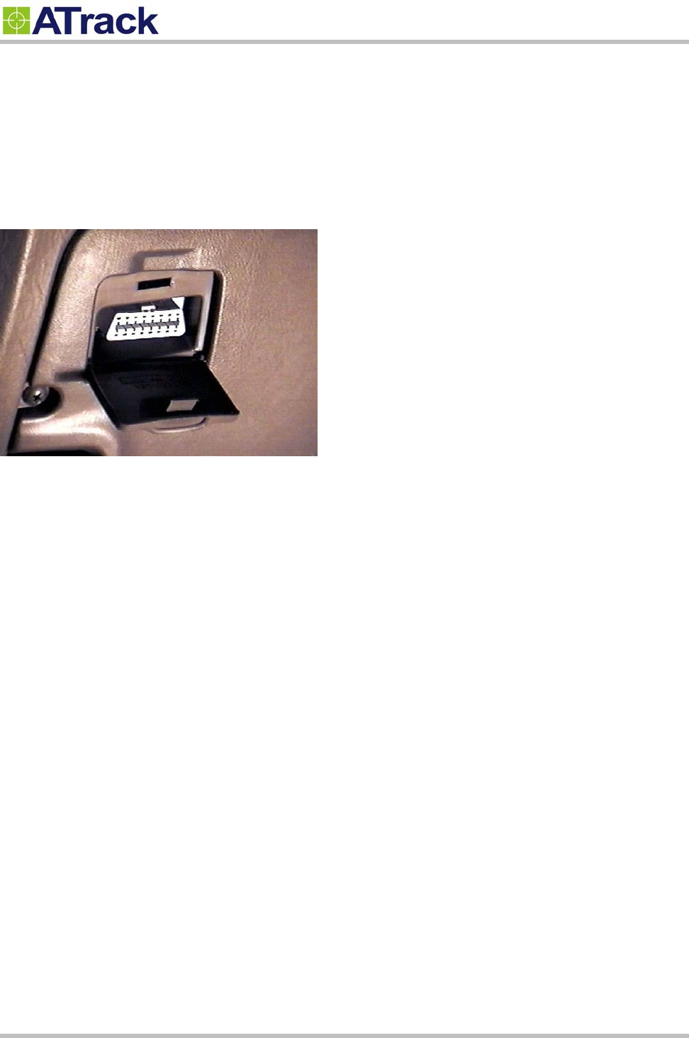
The ODB-II DLC location is different for every kind of vehicles. For example, the DLC is covered by plastic
cover like picture below. The AX7 device is too long to hide when AX7 plug into the DLC connector. The low
profile OBD-II extension cable can solve this problem. Another advantage of this cable is to re-location of the
AX7 device for better GPS performance.
Confidential Document
© ATrack Technology Inc. All Rights Reserved. Page 18 of 21
5
5.
.3
3.
.
G
GP
PS
S
P
Pe
er
rf
fo
or
rm
ma
an
nc
ce
e
f
fo
or
r
I
In
ns
st
ta
al
ll
la
at
ti
io
on
n
The AX7 determines its position by communicating with the Global Positioning Satellites through internal GPS
antenna. The location chosen of the AX7 will have a lot to do with the overall performance of the GPS receiver.
The AX7 device has internal GPS antenna but it is not a water proof design. Therefore, it shall be interior
installed. Please note that the following interior conditions may cause bad GPS reception of AX7:
Your vehicle has metallic window tint
Your vehicle has a windshield mounted radio antenna
Your vehicle has a solar reflective window
The AX7 installation direction shall be considered as well. Please see the following figure:
The AX7 used the latest GPS autonomous technology which accelerates GPS positioning by capitalizing on
the periodic nature of GPS satellite orbits. GPS orbit predictions are directly calculated by the GPS receiver
and no external aiding data or connectivity is required. Therefore, more satellites received are benefit for GPS
fix under low signal environment for the next 3~4 days.
Good for GPS reception
Sky
Acceptable
Bad for GPS reception
GPS Antenna
DLC Connector
Confidential Document
© ATrack Technology Inc. All Rights Reserved. Page 19 of 21
5
5.
.4
4.
.
S
Si
im
mp
pl
le
e
V
Ve
er
ri
if
fi
ic
ca
at
ti
io
on
n
f
fo
or
r
I
In
ns
st
ta
al
ll
la
at
ti
io
on
n
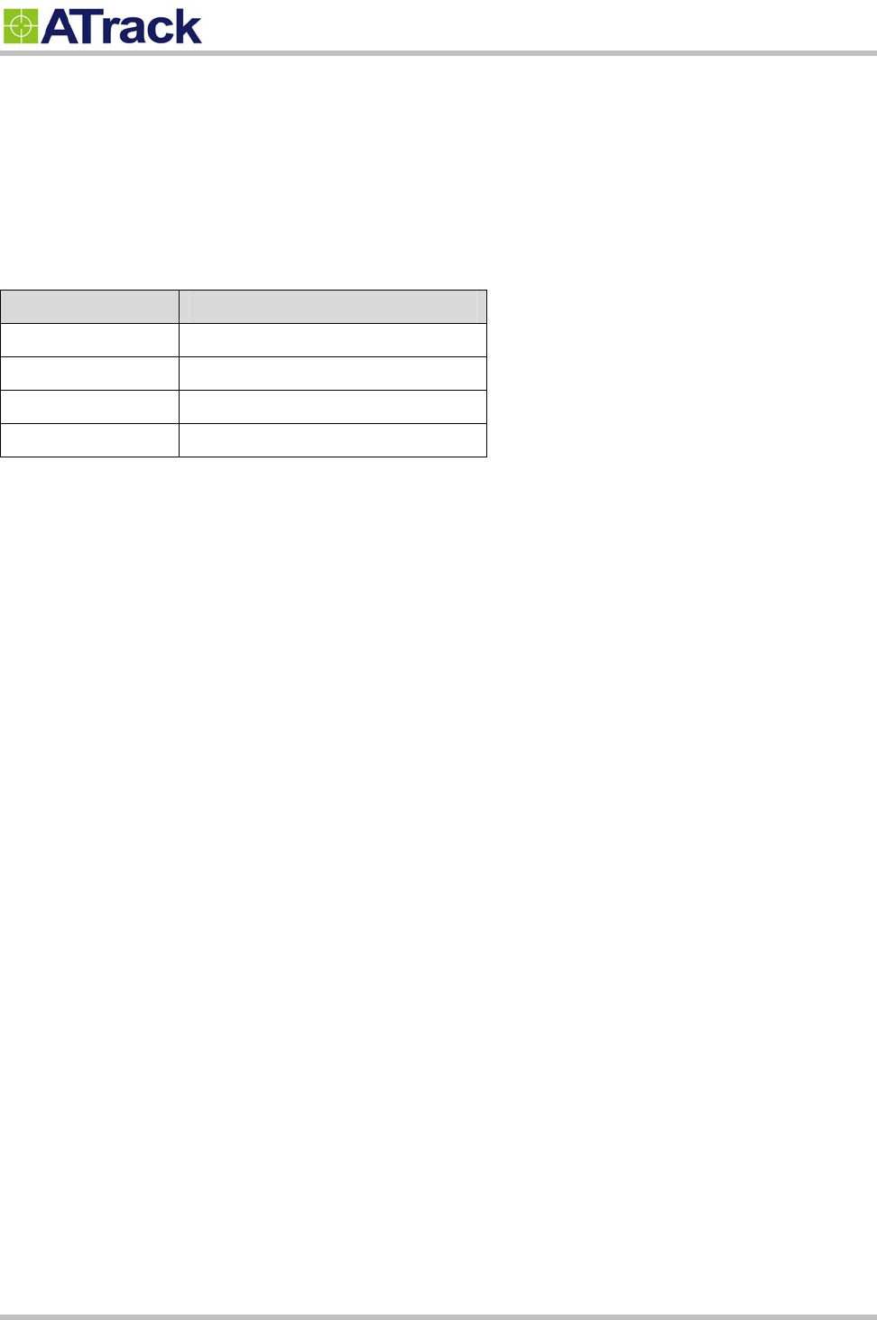
When the device is configured and first plugged into the OBD port. The AX7 will have some buzzer indications
for basic function test. The user can simply to verify if the AX7 device is installed properly.
Buzzer Indication Description
Beep 1 time Device Power ON
Beep 2 times OBD Protocol Connected
Beep 3 times CDMA Connected
Beep 4 times GPS Fix
Confidential Document
© ATrack Technology Inc. All Rights Reserved. Page 20 of 21
6
6.
.
A
Ap
pp
pe
en
nd
di
ix
x
6
6.
.1
1.
.
H
Ha
ar
rd
dw
wa
ar
re
e
S
Sp
pe
ec
ci
if
fi
ic
ca
at
ti
io
on
n
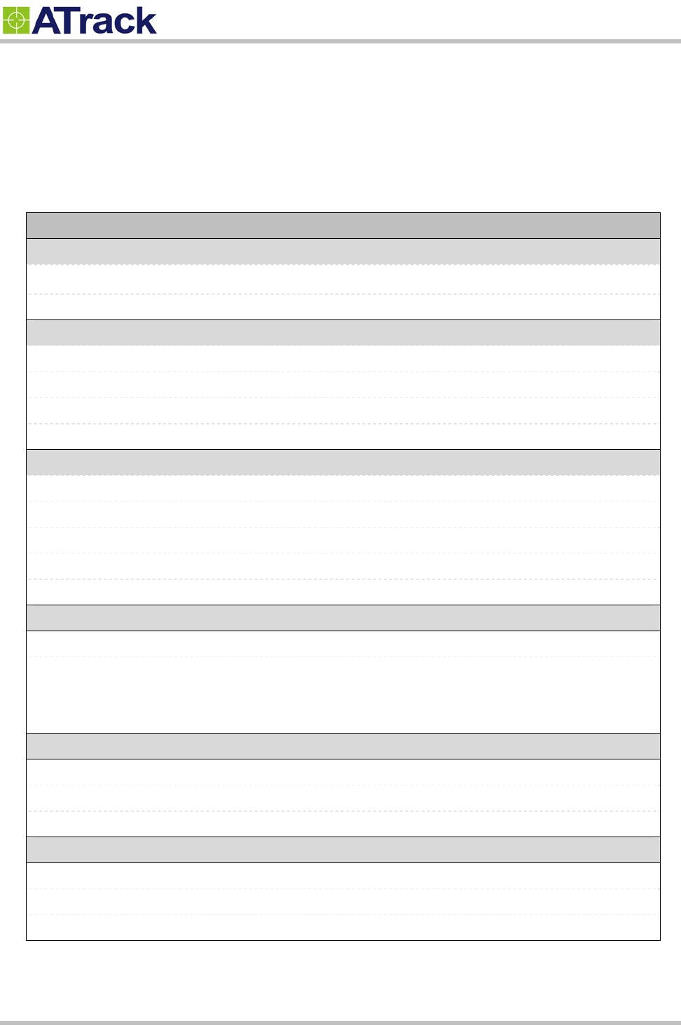
AX7
CDMA Specification
CDMA Module Dual band CDMA 850/1900MHz
CDMA Antennas Internal Type
GPS Specification
GPS Receiver 50 Channels, L1 Band, C/A Code
Sensitivity -159dBm
Accuracy 2.5m CEP
Assisted GPS Supported
OBD-II Specification
Supported Protocol ISO 15765-4 (CAN)
ISO 14230-4 (KWP2000)
ISO 9141-2 (Asian, European, Chrysler vehicles)
SAE J1850 VPW (GM vehicles)
SAE J1850 PWM (Ford vehicles)
Electrical Characteristics
Power Source 8-35 VDC
Power Consumption Operational 140 mA @ 12VDC (Average)
Sleep 18 mA @ 12VDC
Deep Sleep <2 mA @ 12VDC
Mechanical Specification
Dimension 50 x 46 x 25 mm
OBD Connector SAE J1962 Type A
Weight 54g (Include OBD Option)
Environmental Characteristics
Operation Temperature -25 ~ +70°C
Storage Temperature -40 ~ +85°C
Humidity 5 ~ 95%

Confidential Document
© ATrack Technology Inc. All Rights Reserved. Page 21 of 21
6
6.
.2
2.
.
F
FC
CC
C
R
Re
eg
gu
ul
la
at
ti
io
on
ns
s:
:
This device complies with part 15 of the FCC Rules. Operation is subject to the following two
conditions: (1) This device may not cause harmful interference, and (2) this device must accept any
interference received, including interference that may cause undesired operation.
This device has been tested and found to comply with the limits for a Class B digital device, pursuant
to Part 15 of the FCC Rules. These limits are designed to provide reasonable protection against harmful
interference in a residential installation. This equipment generates, uses and can radiated radio
frequency energy and, if not installed and used in accordance with the instructions, may cause harmful
interference to radio communications. However, there is no guarantee that interference will not occur in
a particular installation If this equipment does cause harmful interference to radio or television reception,
which can be determined by turning the equipment off and on, the user is encouraged to try to correct
the interference by one or more of the following measures:
-Reorient or relocate the receiving antenna.
-Increase the separation between the equipment and receiver.
-Connect the equipment into an outlet on a circuit different from that to which the receiver is connected.
-Consult the dealer or an experienced radio/TV technician for help.
Changes or modifications not expressly approved by the party responsible for compliance could void the
user‘s authority to operate the equipment.
RF Exposure Information
This device meets the government’s requirements for exposure to radio waves.
This device is designed and manufactured not to exceed the emission limits for exposure to radio
frequency (RF) energy set by the Federal Communications Commission of the U.S. Government.
This device complies with FCC radiation exposure limits set forth for an uncontrolled environment. In
order to avoid the possibility of exceeding the FCC radio frequency exposure limits, human proximity to
the antenna shall not be less than 20cm (8 inches) during normal operation.