Accton Technology 7004ACC Barricade 2.4GHz 11Mbps Wireless Cable/DSL Router User Manual SMC7004AWBRV2
Accton Technology Corp Barricade 2.4GHz 11Mbps Wireless Cable/DSL Router SMC7004AWBRV2
Contents
- 1. User Manual Part 1
- 2. User Manual Part 2
User Manual Part 1

SMC7004AWBR

38 Tesla
Irvine, CA 92618
Phone: (949) 679-8000
BarricadeTM 2.4 GHz 11 Mbps Wireless
Cable/DSL Broadband Router with
Print Server
User Guide
From SMC’s Barricade line of Broadband Routers
April 2003
Pub. # 01-111234-001

COPYRIGHT
Information furnished by SMC Networks, Inc. (SMC) is believed to be accurate and reliable.
However, no responsibility is assumed by SMC for its use, nor for any infringements of patents
or other rights of third parties which may result from its use. No license is granted by
implication or otherwise under any patent or patent rights of SMC. SMC reserves the right to
change specifications at any time without notice.
Copyright © 2003 by
SMC Networks, Inc.
38 Tesla
Irvine, CA 92618
All rights reserved. Printed in Taiwan
Trademarks:
SMC is a registered trademark; and Barricade is a trademark of SMC Networks, Inc. Other
product and company names are trademarks or registered trademarks of their respective
holders.

i
COMPLIANCES
FCC - Class B
This equipment has been tested and found to comply with the limits for a Class B
digital device, pursuant to Part 15 of the FCC Rules. These limits are designed to
provide reasonable protection against harmful interference in a residential
installation. This equipment generates, uses and can radiate radio frequency
energy and, if not installed and used in accordance with instructions, may cause
harmful interference to radio communications. However, there is no guarantee that
the interference will not occur in a particular installation. If this equipment does
cause harmful interference to radio or television reception, which can be
determined by turning the equipment off and on, the user is encouraged to try to
correct the interference by one or more of the following measures:
• Reorient the receiving antenna
• Increase the separation between the equipment and receiver
• Connect the equipment into an outlet on a circuit different from that to
which the receiver is connected
• Consult the dealer or an experienced radio/TV technician for help
- Consult the dealer or an experienced radio/TV technician for help.
FCC Caution: To assure continued compliance, (example - use only shielded
interface cables when connecting to computer or peripheral devices) any changes
or modifications not expressly approved by the party responsible for compliance
could void the user's authority to operate this equipment.
This device complies with Part 15 of the FCC Rules. Operation is subject to the
following two conditions: (1) This device may not cause harmful interference, and
(2) this device must accept any interference received, including interference that
may cause undesired operation.
IMPORTANT NOTE:
FCC Radiation Exposure Statement:
This equipment complies with FCC radiation exposure limits set forth for
an uncontrolled environment. This equipment should be installed and operated
with a minimum distance of 20 centimeters (8 inches) between the radiator and
your body. This transmitter must not be co-located or operating in conjunction with
any other antenna or transmitter.
Industry Canada - Class B
This digital apparatus does not exceed the Class B limits for radio noise emissions
from digital apparatus as set out in the interference-causing equipment standard
entitled “Digital Apparatus,” ICES-003 of the Department of Communications.

Compliances
ii
Cet appareil numérique respecte les limites de bruits radioélectriques applicables
aux appareils numériques de Classe B prescrites dans la norme sur le matériel
brouilleur: “Appareils Numériques,” NMB-003 édictée par le ministère des
Communications.
EC Conformance Declaration - Class B
SMC contact for these products in Europe is:
SMC Networks Europe,
Edificio Conata II,
Calle Fructuós Gelabert 6-8, 2o, 4a,
08970 - Sant Joan Despí,
Barcelona, Spain.
This information technology equipment complies with the requirements of the
Council Directive 89/336/EEC on the Approximation of the laws of the Member
States relating to Electromagnetic Compatibility and 73/23/EEC for electrical
equipment used within certain voltage limits and the Amendment Directive 93/68/
EEC. For the evaluation of the compliance with these Directives, the following
standards were applied:
RFI
Emission:
* Limit class B according to EN 55022:1998
* Limit class B for harmonic current emission according to EN 61000-3-2/
1995
* Limitation of voltage fluctuation and flicker in low-voltage supply system
according to EN 61000-3-3/1995
Immunity: * Product family standard according to EN 55024:1998
* Electrostatic Discharge according to EN 61000-4-2:1995
(Contact Discharge: ±4 kV, Air Discharge: ±8 kV)
* Radio-frequency electromagnetic field according to EN 61000-4-3: 1996
(80 - 1000 MHz with 1 kHz AM 80% Modulation: 3 V/m)
* Electrical fast transient/burst according to EN 61000-4-4:1995(AC/DC
power supply: ±1 kV, Data/Signal lines: ±0.5 kV)
* Surge immunity test according to EN 61000-4-5:1995(AC/DC Line to Line:
±1 kV, AC/DC Line to Earth: ±2 kV)
* Immunity to conducted disturbances, Induced by radio-frequency fields:
EN 61000-4-6:1996(0.15 - 80 MHz with 1 kHz AM 80% Modulation: 3 V/m)
* Power frequency magnetic field immunity test according to EN
61000-4-8:1993(1 A/m at frequency 50 Hz)
* Voltage dips, short interruptions and voltage variations immunity test
according to EN 61000-4-11:1994(>95% Reduction @10 ms, 30%
Reduction @500 ms, >95% Reduction @5000 ms)
LVD: * EN60950(A1/1992; A2/1993; A3/1993; A4/1995; A11/1997)

iii
T
ABLE
OF
C
ONTENTS
About theWireless Barricade Router . . . . . . . . . . . . . . .1
LED Indicators . . . . . . . . . . . . . . . . . . . . . . . . . . . . . . . . . . . . . 1
Features and Benefits . . . . . . . . . . . . . . . . . . . . . . . . . . . . . . . . 2
Installing the Wireless Barricade . . . . . . . . . . . . . . . . . .4
Package Contents . . . . . . . . . . . . . . . . . . . . . . . . . . . . . . . . . . 4
Hardware Description . . . . . . . . . . . . . . . . . . . . . . . . . . . . . . . 5
System Requirements . . . . . . . . . . . . . . . . . . . . . . . . . . . . . . . . 8
Connect the System . . . . . . . . . . . . . . . . . . . . . . . . . . . . . . . . . 9
Basic Installation Procedure . . . . . . . . . . . . . . . . . . . . . . 9
Configuring Client TCP/IP . . . . . . . . . . . . . . . . . . . . . .11
Installing TCP/IP . . . . . . . . . . . . . . . . . . . . . . . . . . . . . . . . . . 11
Windows 95/98/Me . . . . . . . . . . . . . . . . . . . . . . . . . . . 11
Windows 2000 . . . . . . . . . . . . . . . . . . . . . . . . . . . . . . . 12
Setting Up TCP/IP . . . . . . . . . . . . . . . . . . . . . . . . . . . . . . . . . 13
Configuring Your Computer in Windows 95/98/2000/Me 14
Verifying Your TCP/IP Connection . . . . . . . . . . . . . . . . 24
Configuring the Wireless Barricade . . . . . . . . . . . . . . .25
Browser Configuration . . . . . . . . . . . . . . . . . . . . . . . . . . . . . . 25
Disable Proxy Connection . . . . . . . . . . . . . . . . . . . . . . . . . . . 26
Internet Explorer (5 or above) . . . . . . . . . . . . . . . . . . . . . . . . 26
Internet Explorer (For Macintosh) . . . . . . . . . . . . . . . . . . . . . . 26
Netscape (4 or above) . . . . . . . . . . . . . . . . . . . . . . . . . . . . . . 27
Navigating the Web Browser Interface . . . . . . . . . . . . . . . . . . 28
Making Configuration Changes . . . . . . . . . . . . . . . . . . . 28
Setup Wizard . . . . . . . . . . . . . . . . . . . . . . . . . . . . . . . . . . . . . 29
Time Zone . . . . . . . . . . . . . . . . . . . . . . . . . . . . . . . . . . 29
Broadband Type . . . . . . . . . . . . . . . . . . . . . . . . . . . . . 29
Advanced Setup . . . . . . . . . . . . . . . . . . . . . . . . . . . . . . . . . . 32
System . . . . . . . . . . . . . . . . . . . . . . . . . . . . . . . . . . . . . 33
WAN . . . . . . . . . . . . . . . . . . . . . . . . . . . . . . . . . . . . . . 35
LAN . . . . . . . . . . . . . . . . . . . . . . . . . . . . . . . . . . . . . . . 43
Wireless Settings (Wireless) . . . . . . . . . . . . . . . . . . . . . . 44

T
ABLE
OF
C
ONTENTS
iv
Network Address Translation (NAT) . . . . . . . . . . . . . . . . 46
Firewall . . . . . . . . . . . . . . . . . . . . . . . . . . . . . . . . . . . . . 50
DDNS (Dynamic DNS) Settings . . . . . . . . . . . . . . . . . . . 61
UPnP (Universal Plug and Play) Setting . . . . . . . . . . . . . 62
Tools . . . . . . . . . . . . . . . . . . . . . . . . . . . . . . . . . . . . . . 62
Configuring the Print Server . . . . . . . . . . . . . . . . . . . . 67
Install the SMC Printer Port Monitor . . . . . . . . . . . . . . . . . . . . . 67
Configure the Print Server . . . . . . . . . . . . . . . . . . . . . . . . . . . . 70
Configure the Network Printer
in Windows 95/98/Me/2000 . . . . . . . . . . . . . . . . . 70
Configure the Network Printer in Windows NT . . . . . . . . 72
Configure the Network Printer in Unix Systems . . . . . . . 74
Configure LPR port on Windows 2000/XP . . . . . . . . . . . 74
Troubleshooting . . . . . . . . . . . . . . . . . . . . . . . . . . . . . . 86
Specifications . . . . . . . . . . . . . . . . . . . . . . . . . . . . . . . . 91
1
ABOUT THE
WIRELESS BARRICADE
ROUTER
Congratulations on your purchase of the Barricade™ Wireless
Cable/DSL Broadband Router. SMC is proud to provide you with
a powerful yet simple communication device for connecting your
local area network (LAN) to the Internet.
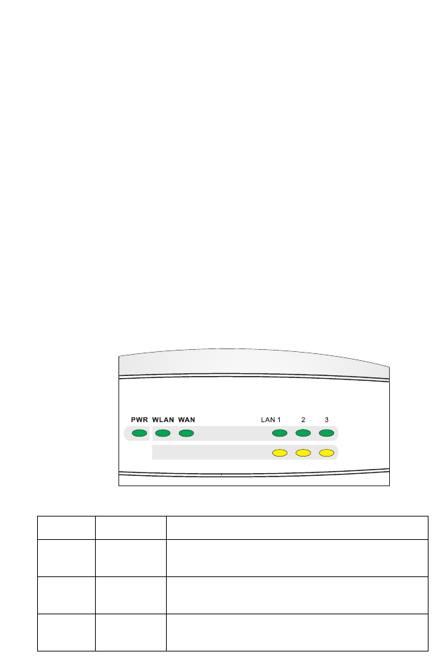
LED Indicators
The SMC7004AWBR includes status LED indicators, as
described in the following figure and table.
LED Condition Status
PWR
(Green) On Wireless Barricade is receiving power.
WLAN
(Green) On The Wireless Barricade has established a valid
wireless connection.
WAN
(Green) On The WAN port has established a valid network
connection.
Link/Act
Speed

About the Wireless Barricade Router
2
Features and Benefits
•Internet connection to xDSL or Cable modem via a
10/100 Mbps WAN port
•Internet connection to ISDN TA or PSTN modem via an
RS-232 serial port
•Local network connection via 10/100 Mbps Ethernet ports or
11 Mbps wireless interface (supporting up to 128 mobile
users)
•802.11b Compliant – interoperable with multiple vendors
•Provides seamless roaming within an 802.11b WLAN
environment
•Supports 64-bit and 128-bit WEP (Wired Equivalent Privacy)
•Built-in Print Server allows direct connection of a printer
•DHCP for dynamic IP configuration, and DNS for domain
name mapping
LAN
Link/Act
(Green) On The indicated LAN port has established a valid
network connection.
Flashing The indicated LAN port is transmitting or
receiving traffic.
Speed
(Amber) On The port is transmitting or receiving traffic ar
100 Mbps.
Off The port is transmitting or receiving traffic
at 10 Mbps.
LED Condition Status

Features and Benefits
3
•Firewall with client privileges, hacker prevention, and NAT
(Network Address Translation)
•NAT also enables multi-user access with a single-user
account, and virtual server functionality (providing protected
access to Internet services such as Web, FTP, mail and
Telnet)
•Virtual Private Network support using PPTP, L2TP or IPSec
pass-through
•User-definable application sensing tunnel supports
applications requiring multiple connections
•Supports CHAP authentication protocol for dial-up
identification
•Supports PPP dial-out connection
•Easy setup through a Web browser on any operating system
that supports TCP/IP
•Compatible with all popular Internet applications

4
INSTALLING THE WIRELESS
BARRICADE
Before installing the Wireless Barricade, verify that you have all
the items listed under “Package Contents.” If any of the items are
missing or damaged, contact your local SMC distributor. Also be
sure that you have all the necessary cabling before installing the
Wireless Barricade. After installing the Wireless Barricade, refer
to the Web-based configuration program in “Configuring the
Wireless Barricade” on page 25 for information on configuring the
router.
Package Contents
After unpacking the Wireless Barricade check the contents of the
box to be sure you have received the following components:
•Barricade Broadband Wireless Router
•Power adapter
•One CAT-5 Ethernet cable
•Four rubber feet
•Installation CD containing this User Guide and EZ 3-Click
Installation Wizard
•Quick Installation Guide
Immediately inform your dealer in the event of any incorrect,
missing or damaged parts. If possible, please retain the carton
and original packing materials in case there is a need to return
the product.
Please register on SMC’s Web site at www.smc.com.

Hardware Description
5
Hardware Description
The Wireless Barricade may be connected to the Internet or to a
remote site using its RJ-45 WAN port or RS-232 serial port. It can
be connected directly to your PC or to a local area network using
any of the three Fast Ethernet LAN ports or through the wireless
interface. It also functions as a print server.
Access speed to the Internet depends on your service type.
Full-rate ADSL provides up to 8 Mbps downstream and 640
Mbps upstream. G.lite (or splitterless) ADSL provides up to 1.5
Mbps downstream and 512 Kbps upstream. Cable modems
provide up to 36 Mbps downstream and 2 Mbps upstream. ISDN
provides up to 128 Kbps when using two bearer channels. And
PSTN analog connections can now run up to 56 Kbps. However,
you should note that the actual rate provided by specific service
providers may vary dramatically from these upper limits.
Though Internet access speed is determined by the modem type
connected to your Wireless Barricade, data passing between
devices connected to your local area network can run up to 100
Mbps over the Fast Ethernet ports.
The Wireless Barricade includes an LED display on the front
panel for system power and port indications that simplifies
installation and network troubleshooting.

Installing the Wireless Barricade
6
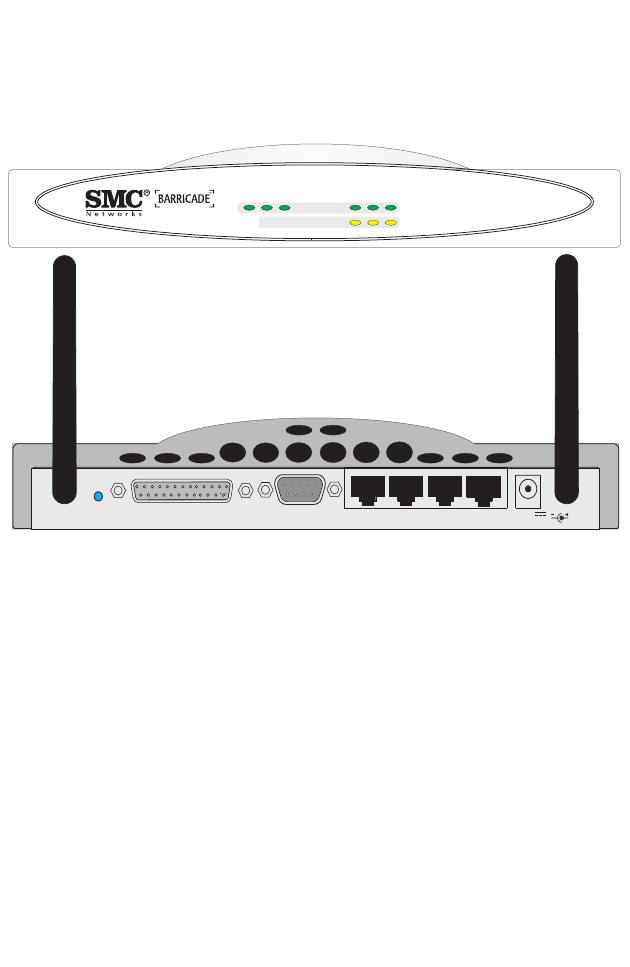
On the rear panel, the Wireless Barricade provides:
•Three RJ-45 ports for connection to a 10BASE-T/
100BASE-TX Ethernet Local Area Network (LAN). These
ports can auto- negotiate the operating speed to 10/100 Mbps,
the mode to half/full duplex, and the pin signals to MDI/MDI-X
(i.e., allowing these ports to be connected to any network
device with straight-through cable).
•These RJ-45 ports can be connected directly to a PC or to a
server equipped with an Ethernet network interface card, or to
a networking device such as an Ethernet hub or switch.
•One RJ-45 port for connection to an xDSL or Cable modem.
This is a 10/100 Mbps, full duplex port, Use a Category 3 or
higher cable to connect this WAN port to a xDSL or Cable
modem.
•One RS-232 serial port to connect to an ISDN Terminal
Adapter (TA) or to a PSTN analog modem.
•One parallel printer port that can be connected to a printer.
This printer can then be shared by any LAN/WLAN users.
•Two external antennas (dipole, omni-directional).
Hardware Description
7
The following figure shows the components of the Wireless
Barricade:
Figure 1. Front and Rear Panels
RESET COM
9V
1 A MAX
9 V
1 A MAX
WAN 12 3
Printer
SMC7004AWBR
LAN 1PWR WLAN WAN 23
Link/Act
Speed

Installing the Wireless Barricade
8
System Requirements
You should meet the following minimum requirements.
•Internet access from your local telephone company or ISP
using an xDSL modem, Cable modem, ISDN TA, or PSTN
analog modem. You may also have access over the telephone
system to an analog modem at another site.
•A PC using a fixed IP address or dynamic IP address
assignment via DHCP, as well as a Gateway server address
and DNS server address from your service provider.
Item Description
LEDs Power, WLAN, WAN and LAN port status indicators.
(See “LED Indicators” on page 1.)
Wireless
Antennas Dual antennas provide optimal reception by dynamically
choosing the best antenna for each client.
Reset
Button Use this button to reset the power and restore the default
factory settings.
Printer
Port Parallel port (25-pin, D-type, female). Connect the shared
printer to this port.
COM Port Serial port (9-pin, D-type, male). Connect your ISDN TA or
56K analog modem to this port.
WAN Port WAN port (RJ-45). Connect your Cable modem, xDSL
modem, or an Ethernet router to this port.
LAN Ports Fast Ethernet ports (RJ-45). Connect devices on your local
area network to these ports (such as a PC, hub, or switch).
Power
Inlet Connect the included power adapter to this inlet.
Warning: The included power adapter is DC 9 V/1 A. Using
the wrong type of power adapter may cause damage.

Connect the System
9
•For wired LAN connection, you need a computer equipped
with a 10 Mbps, 100 Mbps, or 10/100 Mbps Fast Ethernet
card,or a USB-to-Ethernet converter. For wireless LAN
connections, each computer must have an IEEE 802.11b
compatible wireless adapter.
•TCP/IP network protocols installed on each PC that needs to
access the Internet.
•A Java-enabled Web browser, such as Microsoft Internet
Explorer 5.0 or above, or Netscape Communicator 4.0 or
above installed on one PC at your site for configuring the
Wireless Barricade.
Connect the System
The Wireless Barricade can be positioned at any convenient
location in your office or home. No special wiring or cooling
requirements are needed. You should, however comply with the
following guidelines:
•Keep the Wireless Barricade away from any heating devices.
•Do not place the Wireless Barricade in a dusty or wet
environment.
You should also remember to turn off the power, remove the
power cord from the outlet, and keep your hands dry when you
install the Wireless Barricade.
Basic Installation Procedure
1. Connect the LAN: You can connect the Wireless Barricade to
your PC, or to a hub or switch. Run Ethernet cable from one
of the LAN ports of the Wireless Barricade to your computer’s
network adapter or to another network device.
Installing the Wireless Barricade
10
You may also connect the Wireless Barricade to your PC
(using a wireless client adapter) via radio signals. Position
both antennas on the back of the Wireless Barricade into the
desired positions.
For more effective coverage, you may want to position one
antenna along the vertical axis and the other antenna along
the horizontal axis. (The antennas emit signals along the
toroidal plane – and thus provide more effective
coverage when positioned along alternate axes.)
2. Connect the WAN: Prepare an Ethernet cable for connecting
the Wireless Barricade to a cable/DSL modem or Ethernet
router. Prepare a serial cable for connecting the Wireless
Barricade to an ISDN TA or PSTN modem.
3. Connect your printer: Use standard parallel printer cable to
connect your printer to the printer port on the Wireless
Barricade.
4. Power on: Connect the power adapter to the Wireless
Barricade.
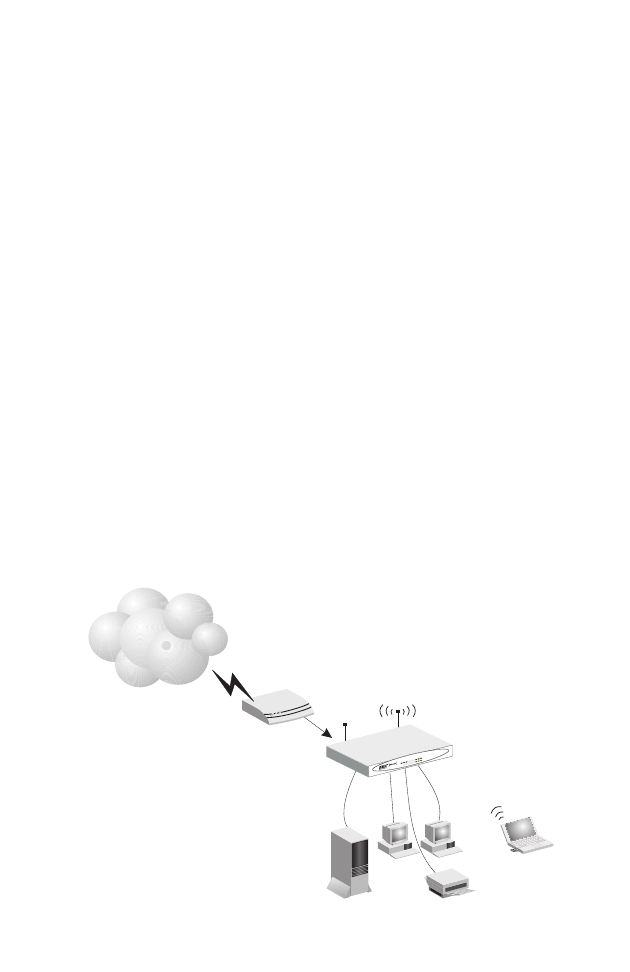
Figure 2. Connecting the Wireless Barricade
Internet
Internet
Access
Device
SMC7004AWBR
Wireless Broadband Router
SOHO Office or Residence
SMC7004AWBR
LAN1
PWRWLAN WAN 23
Link
Activity
Notebook with
Wireless PC Card
11
CONFIGURING
CLIENT TCP/IP
If you have not previously installed the TCP/IP protocols on your
client PCs, refer to the following section. If you need information
on how to configure a TCP/IP address on a PC, refer to “Setting
Up TCP/IP” on page 13.
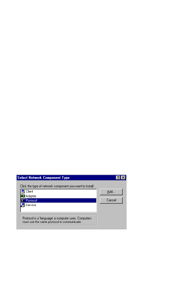
Installing TCP/IP
Windows 95/98/Me
1. Click Start/Settings/Control Panel.
2. Double-click the Network icon and select the Configuration
tab in the Network window.
3. Click the Add button.
4. Double-click Protocol.
Configuring Client TCP/IP
12
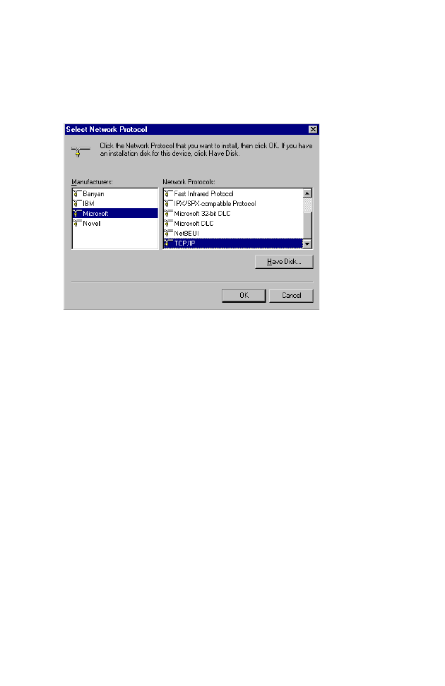
5. Select Microsoft in the manufacturers list. Select TCP/IP in
the Network Protocols list. Click the OK button to return to the
Network window.
6. The TCP/IP protocol will be listed in the Network window.
Click OK. The operating system may prompt you to restart
your system. Click Yes and the computer will shut down and
restart.
Windows 2000
1. Click the Start button and choose Settings, then click the
Network and Dial-up Connections icon.
2. Double-click the Local Area Connection icon, and click the
Properties button on the General tab.
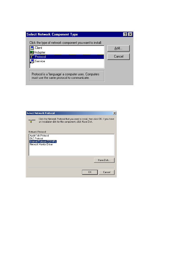
3. Click the install... button.
Setting Up TCP/IP
13
4. Double-click Protocol.
5. Choose Internet Protocol (TCP/IP). Click the OK button to
return to the Network window.
6. The TCP/IP protocol will be listed in the Network window.
Click OK to complete the installation procedure.
Setting Up TCP/IP
To access the Internet through the Wireless Barricade, you must
configure the network settings of the computers on your LAN to
use the same IP subnet as the Wireless Barricade. The default
network settings for the Wireless Barricade are:
IP Address: 192.168.2.1

Configuring Client TCP/IP
14
Subnet Mask: 255.255.255.0
Note: These settings may be changed to suit your network
requirements, but you must first configure at least one
computer as described in this chapter to access the
Wireless Barricade’s Web configuration interface.See
“Configuring the Wireless Barricade” on page 25 for
information on configuring the Wireless Barricade.)
If you have not previously configured TCP/IP for your computer,
refer to“Configuring Client TCP/IP” on page 11. The IP address
of the connected client PC should be 192.168.2.x (where x
means 2–254). You can set the IP address for client PCs either
by automatically obtaining an IP address from the Wireless
Barricade’s DHCP service or by manual configuration.
Configuring Your Computer in Windows 95/98/2000/Me
You may find that the instructions here do not exactly match your
version of Windows. This is because these steps and
screenshots were created in Windows 98. Windows 95 and
Windows Millennium Edition are very similar, but not identical, to
Windows 98.
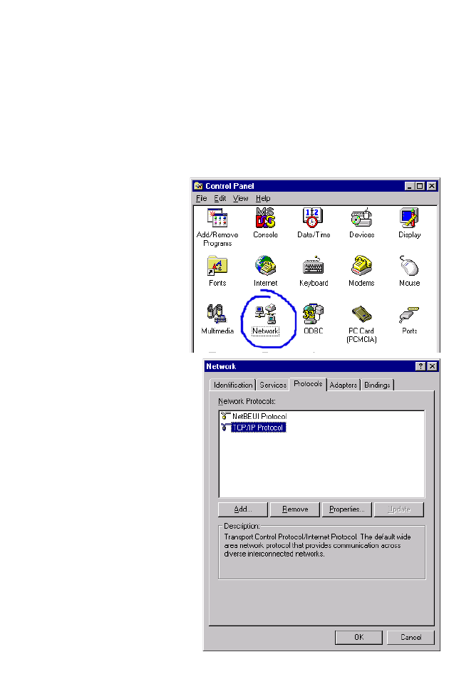
1. From the Windows desktop, click Start/Settings/Control
Panel.
2. In the Control Panel, locate and double click the Network icon.
Setting Up TCP/IP
15
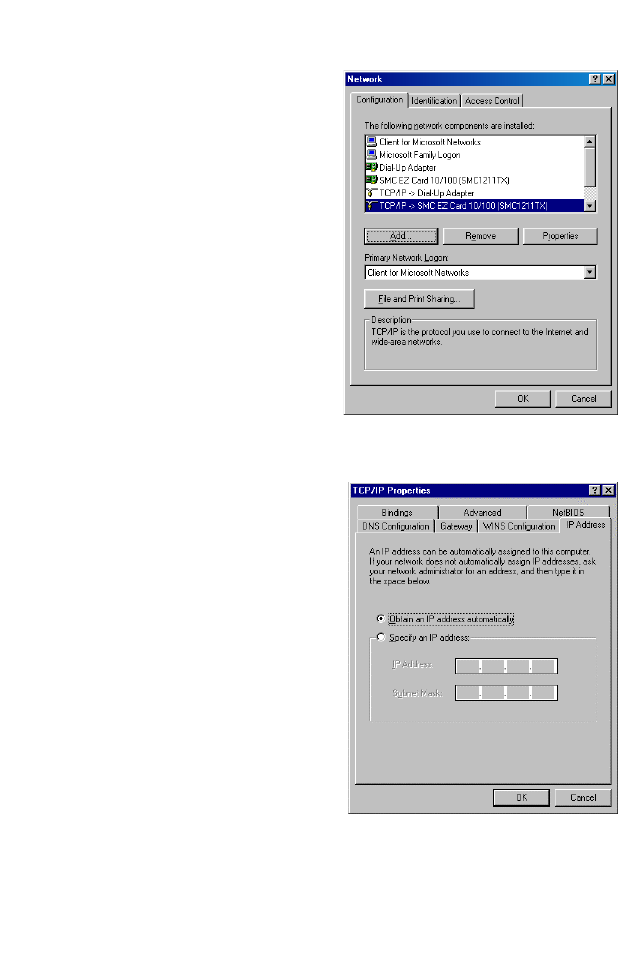
3. On the Network window
Configuration tab,
double-click the TCP/IP
entry for your network
card.
4. Click the IP Address tab.
5. Click the “Obtain an IP
address “option.
6. Next click on the Gateway
tab and verify the Gateway
field is blank. If there are
IP addresses listed in the Gateway section, highlight each
one and click Remove until the section is empty.
7. Click the OK button to close the TCP/IP Properties window.
Configuring Client TCP/IP
16
8. On the Network Properties Window, click the OK button to
save these new settings.
Note: Windows may ask you for the original Windows
installation disk or additional files. Check for the files at
c:\windows\options\cabs, or insert your Windows
CD-ROM into your CDROM drive and check the correct
file location, e.g., D:\win98, D:\win9x. (if D is the letter
of your CD-ROM drive).
9. Windows may prompt you to restart the PC. If so, click the Yes
button. If Windows does not prompt you to restart your
computer, do so to insure your settings.
Obtain IP Settings from Your Wireless Barricade
Now that you have configured your computer to connect to your
Wireless Barricade, it needs to obtain new network settings. By
releasing old IP settings and renewing them with settings from
your Wireless Barricade, you will also verify that you have
configured your computer correctly.
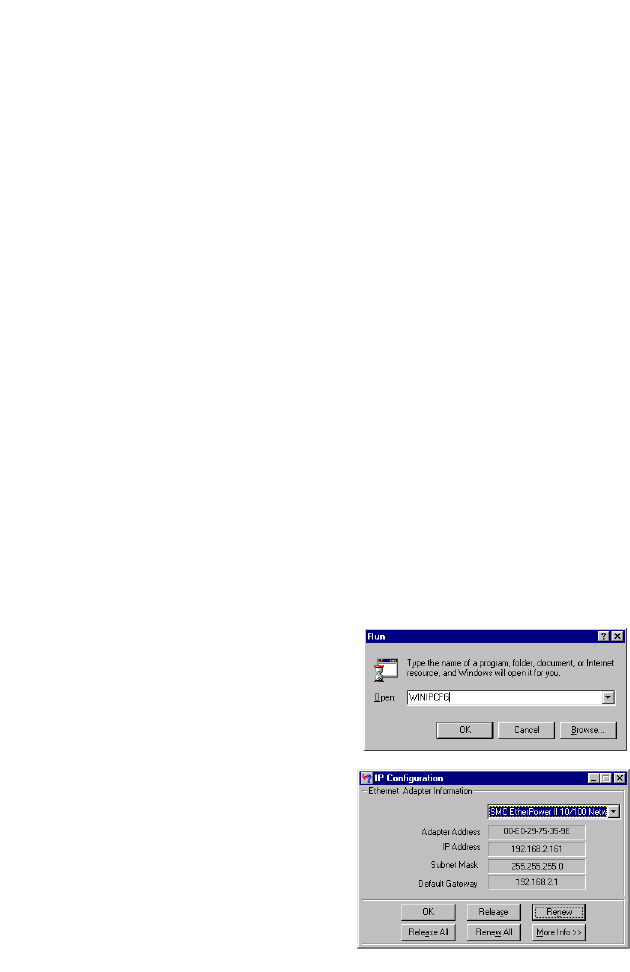
1. Click Start/Run.
2. Type WINIPCFG and click
OK.
3. From the drop-down menu,
select your network card.
Click Release and then
Renew. Verify that your IP
address is now
192.168.2.xxx, your Subnet
Mask is 255.255.255.0 and
your Default Gateway is
Setting Up TCP/IP
17
192.168. 2.1. These values confirm that your Wireless
Barricade is functioning. Click OK to close the IP
Configuration window.
Configuring Your Computer in Windows NT 4.0
1. From the Windows desktop click Start/Settings/Control Panel.
2. Double-click the
Network icon.
3. Click on the
Protocols tab.
4. Double-click TCP/
IP Protocol.
Configuring Client TCP/IP
18
5. Click on the IP Address tab.
6. In the Adapter drop-down list, be sure your Ethernet adapter
is selected.
7. Click on “Obtain an IP address from a DHCP server”.
8. Click OK to close the window.
9. Windows may copy files and will then prompt you to restart
your system. Click Yes and your computer will shut down and
restart.
Obtain IP Settings From Your Wireless Barricade
Now that you have configured your computer to connect to the
Wireless Barricade, it needs to obtain new network settings. By
releasing old IP settings and renewing them with settings from
the Wireless Barricade, you will also verify that you have
configured your computer correctly.
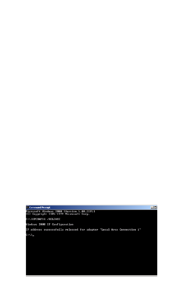
1. On the Windows desktop, click Start/Programs/Command
Prompt.
2. In the Command Prompt window, type IPCONFIG /RELEASE
and press the <ENTER> key.
Setting Up TCP/IP
19
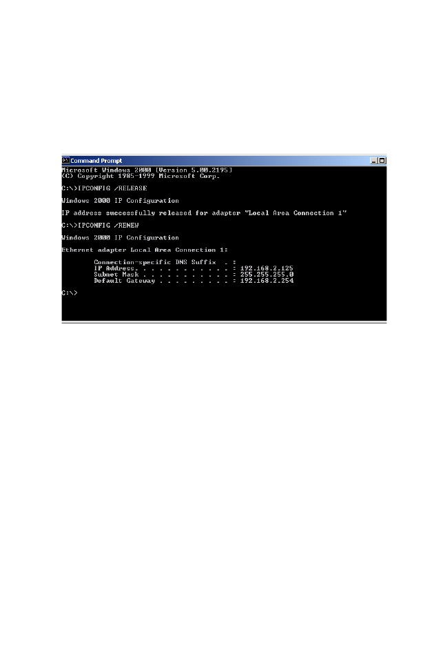
3. Type IPCONFIG /RENEW and press the <ENTER> key. Verify
that your IP Address is now 192.168.2.xxx, your Subnet Mask
is 255.255.255.0 and your Default Gateway is 192.168.2.1.
These values confirm that the Wireless Barricade is
functioning.
4. Type EXIT and press <ENTER> to close the Command
Prompt window.
Configuring Your Computer in Windows 2000
1. Access your Network settings by clicking Start, then choose
Settings and then select Control Panel.
2. In the Control Panel, locate and double-click the Network and
Dial-up Connections icon.
Configuring Client TCP/IP
20
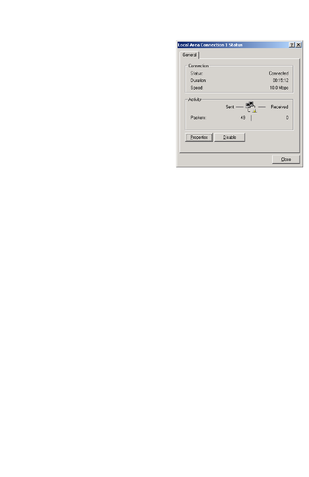
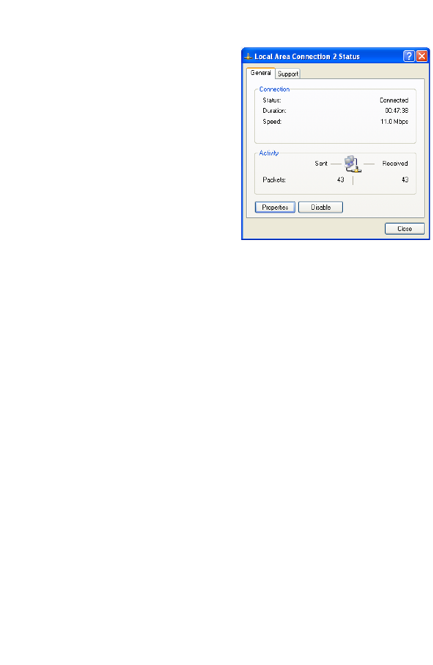
3. Locate and double-click the
Local Area Connection icon
for the Ethernet adapter that
is connected to the Wireless
Barricade. When the Status
dialog box window opens,
click the Properties button.
4. In the Local Area
Connection Properties box,
verify the box next to
Internet Protocol (TCP/IP) is
checked. Then highlight the Internet Protocol (TCP/IP), and
click the Properties button.
5. Select “Obtain an IP address automatically” to configure your
computer for DHCP. Click the [OK] button to save this change
and close the Properties window.
6. Click the OK button again to save these new changes.
7. Reboot your PC.
8. To obtain new network settings see “Obtain IP Settings from
Your Wireless Barricade” on page 16.
Configuring Your Computer in Windows XP
The following instructions assume you are running Windows XP
with the default interface. If you are using the Classic interface
(where the icons and menus look like previous Windows
versions), please follow the instructions for Windows 2000
outlined above.
1. Access your Network settings by clicking Start, choose
Control Panel, select Network and Internet Connections and
then click on the Network Connections icon.
Setting Up TCP/IP
21
2. Locate and double-click the
Local Area Connection icon
for the Ethernet adapter that
is connected to the Wireless
Barricade. Next, click the
Properties button.
3. In the Local Area Connection Properties box, verify the box
next to Internet Protocol (TCP/IP) is checked. Then highlight
the Internet Protocol (TCP/IP), and click the Properties
button.
4. Select “Obtain an IP address automatically” to configure your
computer for DHCP. Click the OK button to save this change
and close the Properties window.
5. Click the OK button again to save these new changes.
6. Reboot your PC.
Configuring a Macintosh Computer
You may find that the instructions here do not exactly match your
screen. This is because these steps and screenshots were
created using Mac OS 8.5. Mac OS 7.x and above are all very
similar, but may not be identical to Mac OS 8.5.
1. Pull down the Apple Menu. Click Control Panel and select
TCP/IP.
Configuring Client TCP/IP
22
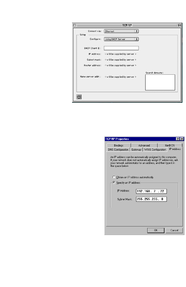
2. In the TCP/IP
dialog box,
make sure that
Ethernet is
selected in the
Connect Via:
field.
3. Select Using
DHCP Server
in the
Configure
field.
Manual IP Configuration
1. Check Specify an IP
address on the IP Address
tab. Enter an IP address
based on the default
network 192.168.2.x (where
x is
between 2 and 254), and
use 255.255.255.0 for the
subnet mask.
Setting Up TCP/IP
23
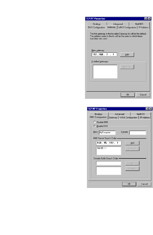
2. In the Gateway tab, add the
IP address of the Wireless
Barricade (default:
192.168.2.1) in the New
gateway field and click Add.
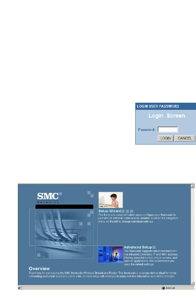
3.
On the DNS Configuration tab,
add the IP address for the
Wireless Barricade
and click
Add. This automatically
relays DNS requests to the
DNS server(s) provided by
your ISP. Otherwise, add
specific
DNS servers into the
DNS Server Search Order
field and click Add.
4. After finishing TCP/IP setup,
click OK, and then reboot
the computer. After that, set
up other PCs on the LAN according to the procedures
described above.

Configuring Client TCP/IP
24
Verifying Your TCP/IP Connection
After installing the TCP/IP communication protocols and
configuring an IP address in the same network as the Wireless
Barricade, use the Ping command to check if your computer has
successfully connected to the Wireless Barricade. The following
example shows how the Ping procedure can be executed in an
MS-DOS window. First, execute the Ping command:
ping 192.168.2.1
If a message similar to the following appears:
Pinging 192.168.2.1 with 32 bytes of data:
Reply from 192.168.2.1: bytes=32 time=2ms TTL=64
a communication link between your computer and the Wireless
Barricade has been successfully established.
If you get the following message,
Pinging 192.168.2.1 with 32 bytes of data:
Request timed out.
there may be something wrong in your installation procedure.
Check the following items in sequence:
1. Is the Ethernet cable correctly connected between the
Wireless Barricade and the computer?
The LAN LED on the Wireless Barricade and the Link LED of
the network card on your computer must be on.
2. Is TCP/IP properly configured on your computer?
If the IP address of the Wireless Barricade is 192.168.2.1, the
IP address of your PC must be from 192.168.2.2 -
192.168.2.254 and the default gateway must be 192.168.2.1.
If you can successfully Ping the Wireless Barricade you are
now ready to connect to the Internet!

25
CONFIGURING THE
WIRELESS BARRICADE
The Wireless Barricade can be configured by any
Java-supported browser including Internet Explorer 4.0 or above,
or Netscape Navigator 5.0 or above. Using the Web
management interface, you can configure the Wireless Barricade
and view statistics to monitor network activity.
Note: NOTE: Before you attempt to configure your router, if
you have access to the Internet please visit
www.smc.com and download the latest firmware
update to insure your router is running the latest
firmware.
Before you attempt to log into the Wireless Barricade Web-based
Administration, please verify the following.
1. Your browser is configured properly (see below).
2. Disable any firewall or security software that may be running.
3. Confirm that you have a good link LED where your computer
is plugged into the Wireless Barricade. If you don’t have a link
light – then try another cable until you get a good link.
Browser Configuration
Confirm your browser is configured for a direct connection to the
Internet using the Ethernet cable that is installed in the computer.
This is configured through the options/preference section of your
browser.

Configuring the Wireless Barricade
26
Disable Proxy Connection
You will also need to verify that the HTTP Proxy feature of your
web browser is disabled. This is so that your web browser will be
able to view the Wireless Barricade configuration pages. The
following steps are for Internet Explorer and for Netscape.
Determine which browser you use and follow the appropriate
steps.
Internet Explorer (5 or above)
1. Open Internet Explorer. Click Tools, and then select Internet
Options.
2. In the Internet Options window, click the Connections tab.
3. Click the LAN Settings button.
4. Clear all the check boxes and click OK to save these LAN
settings changes.
5. Click OK again to close the Internet Options window.
Internet Explorer (For Macintosh)
1. Open Internet Explorer. Click Edit/Preferences.
2. In the Internet Explorer Preferences window, under Network,
select Proxies.
3. Uncheck all checkboxes and click OK.
Netscape (4 or above)
27
Netscape (4 or above)
1. Open Netscape. Click Edit, and then select Preferences.
2. In the Preferences window, under Category, double-click
Advanced, then select the Proxies option.
3. Check “Direct connection to the Internet.”
4. Click the OK button to save the changes.
To access the Wireless Barricade’s
management interface, enter the SMC
Barricade Wireless Broadband Router IP
address in your Web browser http://
192.168.2.1. Then click LOGIN. (By
default, there is no password.)
The home page displays the Setup Wizard and Advanced Setup
options.

Configuring the Wireless Barricade
28
Navigating the Web Browser Interface
The Wireless Barricade’s management interface features a
Setup Wizard and an Advanced Setup section. Use the Setup
Wizard if you want to quickly set up the Wireless Barricade for
use with a cable modem or DSL modem.
Advanced setup supports more advanced functions like hacker
attack detection, IP and MAC address filtering, intrusion
detection, virtual server setup, virtual DMZ hosts, and other
advanced functions.
Making Configuration Changes
Configurable parameters have a dialog box or a drop-down list.
Once a configuration change has been made on a page, be sure
to click the APPLY or NEXT button at the bottom of the page to
enable the new setting.
Note: To ensure proper screen refresh after a command
entry, ensure that Internet Explorer 5.0 is configured as
follows: Under the menu Tools/Internet Options/
General/Temporary Internet Files/Settings, the setting
for “Check for newer versions of stored pages” should
be “Every visit to the page.”
Setup Wizard
29
Setup Wizard
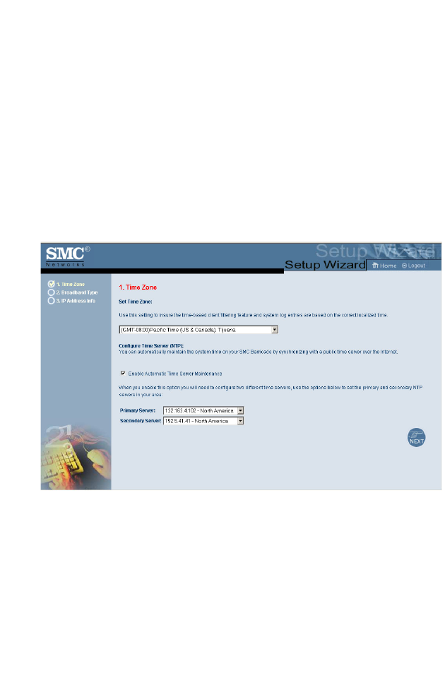
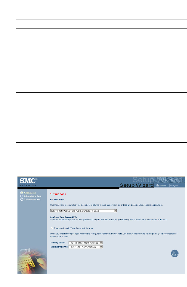
Time Zone
Click on the Setup Wizard picture. The first item in the Setup
Wizard is Time Zone setup.
For accurate timing of client filtering and log events, you need to
set the time zone. Select your time zone from the drop-down list,
and click NEXT.
.
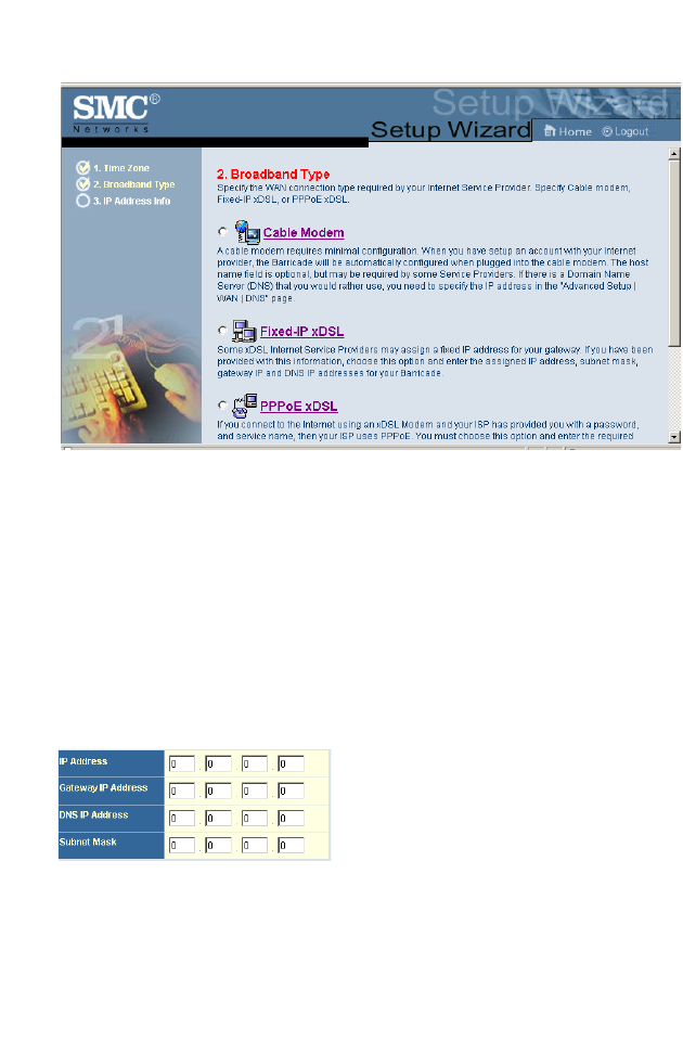
Broadband Type
Select the type of broadband connection you have.
For a cable modem connection see the following page. For a
Fixed-IP xDSL connection see “Fixed-IP xDSL” on page 30, and
for a PPPoE xDSL connection, see “PPPoE” on page 31.
Configuring the Wireless Barricade
30
Cable Modem
After selecting Cable Modem as the Broadband Type, a
message will appear stating that your data has been successfully
saved.
Note: Select Home to return to the home page, then select
Advanced Settings/WAN to configure the required
parameters. (See “WAN” on page 35.)
Fixed-IP xDSL
Some xDSL Internet Service Providers may assign a fixed
(static) IP address. If you have been provided with this
information, choose this option and enter the assigned IP
address, gateway IP address, DNS IP addresses, and subnet
mask. Click FINISH to complete the setup.
Setup Wizard
31
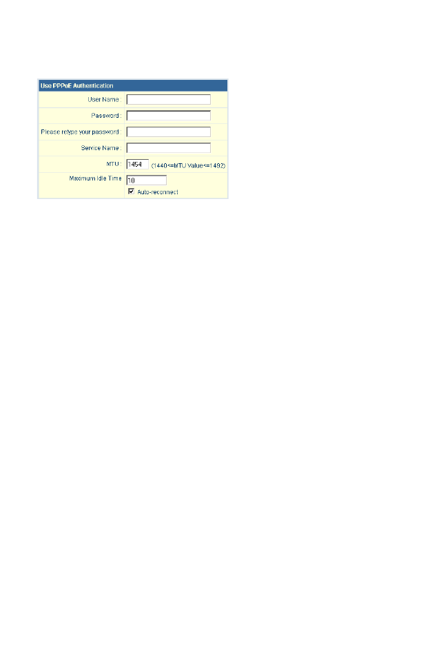
PPPoE
Enter the PPPoE User Name and Password assigned by your
Service Provider. The Service Name is normally optional, but
may be required by some service providers.
Leave the Maximum Transmission Unit (MTU) at the default
value (1454) unless you have a particular reason to change it.
Enter a Maximum Idle Time (in minutes) to define a maximum
period of time for which the Internet connection is maintained
during inactivity. If the connection is inactive for longer than the
Maximum Idle Time, it will be dropped. (Default: 10)
Enable the Auto-reconnect option to automatically re-establish
the connection as soon as you attempt to access the Internet
again. Click FINISH to complete the setup

Configuring the Wireless Barricade
32
Advanced Setup
Use the Web management interface to define system
parameters, manage and control the Wireless Barricade and its
ports, or monitor network conditions. The following table outlines
the selections available from this program.
Menu Description
System Sets the local time zone, the password for administrator
access, and the IP address of a PC that will be allowed to
manage the Wireless Barricade remotely.
WAN Specifies the Internet connection type:
Dynamic IP host configuration and the physical MAC
address of each media interface
PPPoE configuration
PPTP
Static IP and ISP gateway address
BigPond
Specifies DNS servers to use for domain name
resolution.
LAN Sets the TCP/IP configuration of the Wireless Barricade’s
LAN interface and all DHCP clients.
Wireless Configures the radio frequency, domain, and encryption
for wireless communications.
NAT Shares a single ISP account with multiple users, sets up
virtual servers.
Firewall Configures a variety of security and specialized
functions, including: Access Control, Hacker Prevention,
and DMZ.
DDNS Dynamic DNS provides users on the Internet with a
method to tie their domain name(s) to computers or
servers.
Advanced Setup
33
System
Time Zone
UPnP With Universal Plug and Play, a device can automatically
dynamically join a network, obtain an IP address,
communicate its capabilities, and learn about the
presence and capabilities of other devices. Devices can
then directly communicate with each other. This further
enables peer to peer networking.
Tools Contains options to backup & restore the current
configuration, restore all configuration settings to the
factory defaults, update system firmware, or reset the
system.
Status Provides WAN connection type and status, firmware and
hardware version numbers, system IP settings, as well as
DHCP, NAT, and Firewall information.
Displays the number of attached clients, the firmware
versions, the physical MAC address for each media
interface, and the hardware version and serial number.
Shows the security and DHCP client log.
Menu Description
Configuring the Wireless Barricade
34
Sets the time zone for the Wireless Barricade. This information is
used for log entries and client access control.
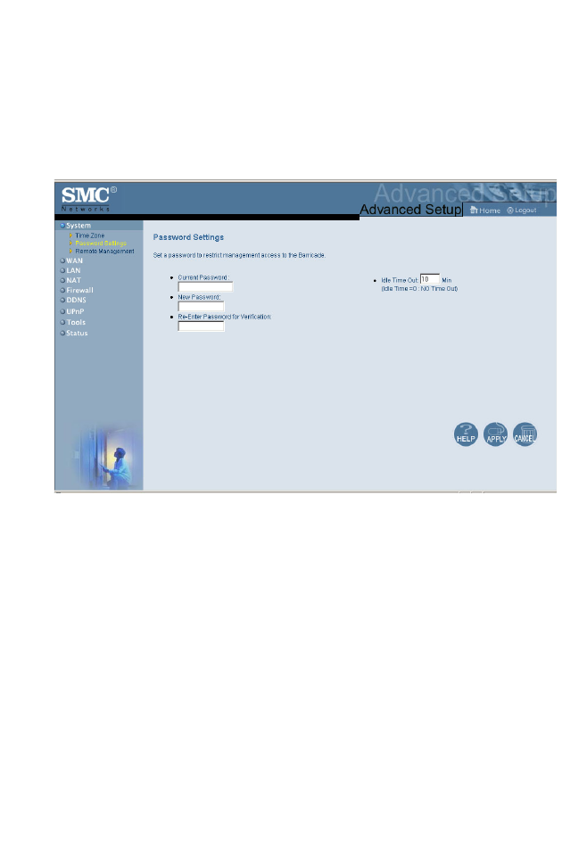
Password Settings
Use this menu to restrict access based on a password. By
default, there is no password. For security reasons you should
assign one before exposing the Wireless Barricade to the
Internet.
Passwords can contain from 3–12 alphanumeric characters and
are not case sensitive.
Note: If your password is lost, or you cannot gain access to
the user interface, press the Reset button on the front
panel (holding it down for at least five seconds) to
restore the factory defaults. (The default is no
password.)
Enter a maximum Idle Time Out (in minutes) to define a
maximum period of time for which the login session is maintained
Advanced Setup
35
during inactivity. If the connection is inactive for longer than the
maximum idle time, it will perform system logout, and you have to
login to the Web management system again. (Default: 10
minutes)
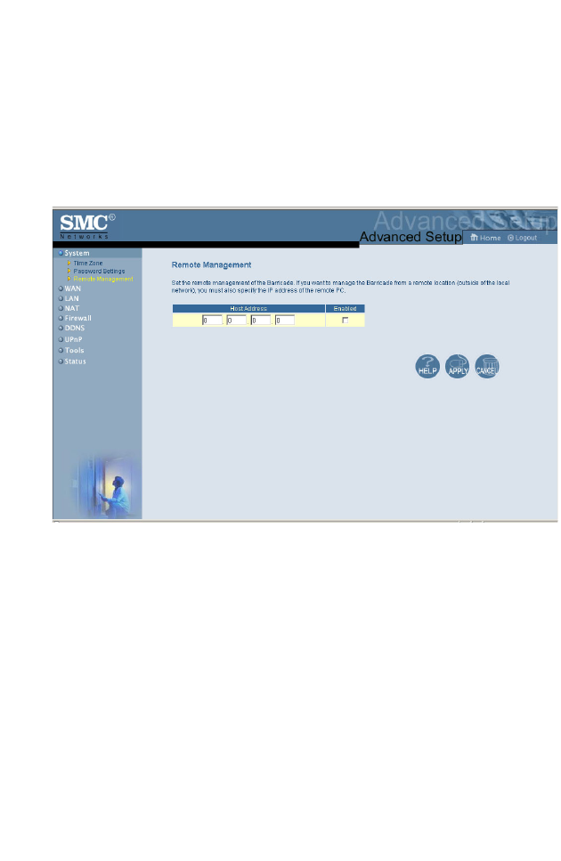
Remote Management
Remote Management allows a remote PC to configure, manage,
and monitor the Wireless Barricade using a standard Web
browser. Check Enable and enter the IP address of the remote
host. Click APPLY.
Note: If you specify 0.0.0.0 as this IP address, any host can
manage the Wireless Barricade.
WAN
Specify the WAN connection type provided by your Internet
Service Provider, then click More Configuration to enter detailed
configuration parameters for the selected connection type.
Configuring the Wireless Barricade
36
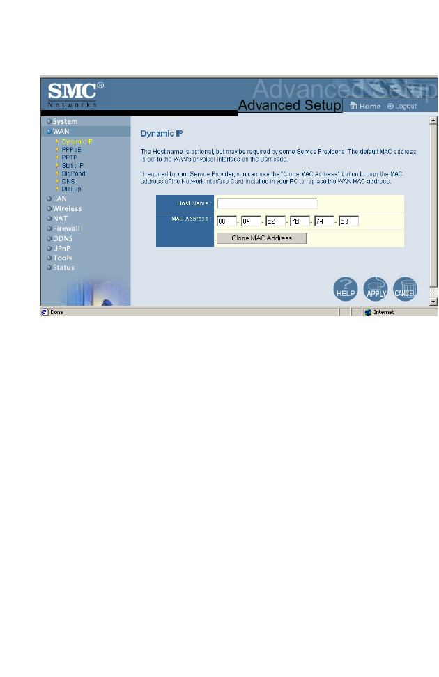
Dynamic IP
The Host Name is optional, but may be required by some ISPs.
The default MAC address is set to the WAN’s physical interface
on the Wireless Barricade. Use this address when registering for
Internet service, and do not change it unless required by your
ISP. If your ISP used the MAC address of an Ethernet card as an
identifier when first setting up your broadband account, only
connect the PC with the registered MAC address to the Wireless
Barricade and click the Clone MAC Address button. This will
replace the current Wireless Barricade MAC address with the
already registered Ethernet card MAC address.
If you are unsure of which PC was originally set up by the
broadband technician, call your ISP and request that they
register a new MAC address for your account. Register the
default MAC address of the Wireless Barricade.
Advanced Setup
37
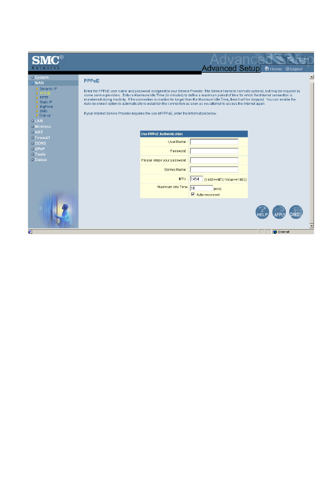
Point-to-Point Over Ethernet (PPPoE)
Enter the PPPoE User Name and Password assigned by your
Service Provider. The Service Name is normally optional, but
may be required by some service providers.
The MTU (Maximum Transmission Unit) governs the maximum
size of the data packets. Leave this on the default value (1454)
unless you have a particular reason to change it.
Enter a Maximum Idle Time (in minutes) to define a maximum
period of time for which the Internet connection is maintained
during inactivity. If the connection is inactive for longer than the
Maximum Idle Time, it will be dropped. (Default: 10 minutes)
Configuring the Wireless Barricade
38
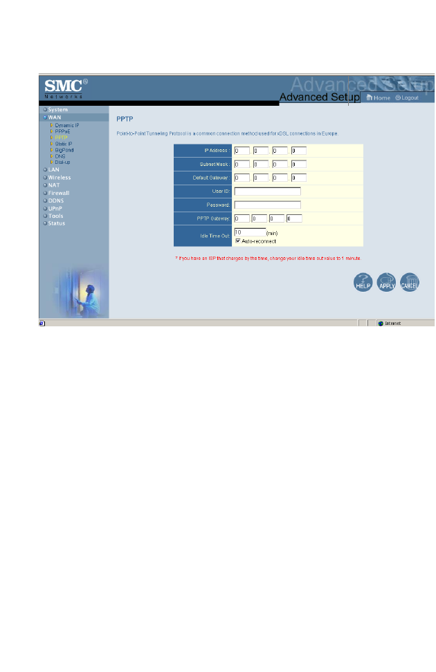
Point-to-Point Tunneling Protocol (PPTP)
Point-to-Point Tunneling Protocol (PPTP) can be used to join
different physical networks using the Internet as an intermediary.
Using the above screen allows client PCs to establish a normal
PPTP session and provides hassle-free configuration of the
PPTP client on each client PC.
Enter the assigned IP address, subnet mask and default gateway
IP address (usually supplied by your ISP), and then the PPTP
User ID, Password and PPPTP Gateway IP address.
Enter a maximum Idle Time Out (in minutes) to define a
maximum period of time for which the PPTP connection is
maintained during inactivity. If the connection is inactive for
longer than the Maximum Idle Time, it will be dropped. (Default:
10 minutes)
Advanced Setup
39
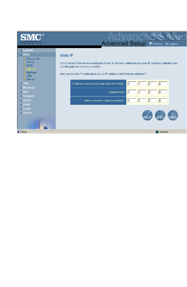
Static IP Address
If your Internet Service Provider has assigned a fixed IP address,
enter the assigned address and subnet mask for the Wireless
Barricade, then enter the gateway address of your ISP.
You may need a fixed address if you want to provide Internet
services, such as a Web server or FTP server.
Configuring the Wireless Barricade
40
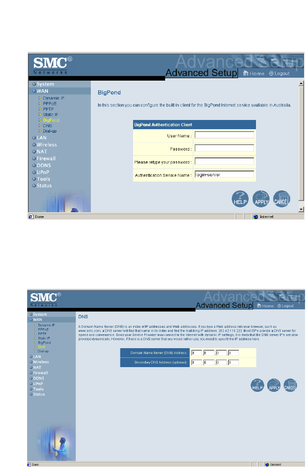
BigPond
Enter your User Name and Password to configure the built-in
client for the BigPond Internet service available in Australia.
DNS
Advanced Setup
41
Domain Name Servers map numerical IP addresses to the
equivalent domain name (e.g., www.smc.com). Your ISP should
provide the IP address of one or more domain name servers.
Enter those addresses in this screen.
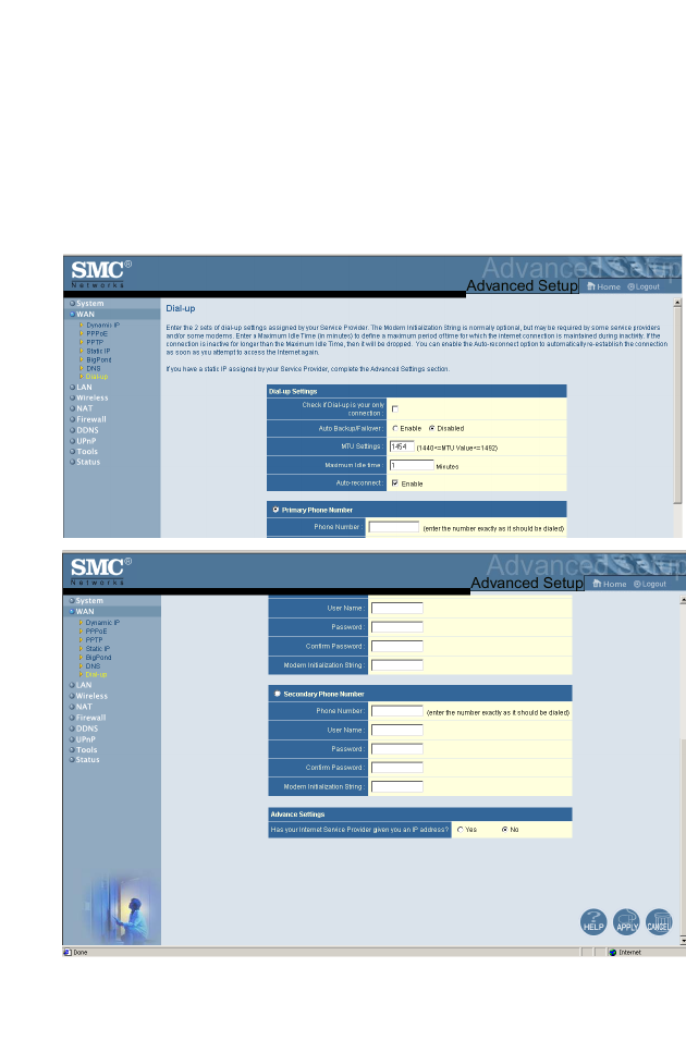
Dial-up
If you are accessing the Internet via an ISDN TA or PSTN
modem attached to the serial port on the Wireless Barricade,

Configuring the Wireless Barricade
42
then you must specify your account information on this screen as
described below.
Note: If not checked, then this connection will only be used
for backup access if the primary WAN link fails
•Auto Backup/Failover – If this is enabled, then if the telephone
connection goes down, the router will automatically redial.
•MTU – Leave the Maximum Transmission Unit (MTU) at the
default value (1454) unless you have a particular reason to
change it.
•Maximum Idle Time – Enter a maximum idle time (in minutes)
to define a maximum period of time for which the Internet
connection is maintained during inactivity (Default: 10). If the
connection is inactive for longer than the Maximum Idle Time,
it will be dropped. Enable the Auto-reconnect option to
automatically re-establish the connection as soon as you
attempt to access the Internet again.
•Phone Number – Enter the phone number your service
provider has given to you for Internet access.
•User Name – Enter your ISP account user name.
•Password – Enter your ISP account password.
•Modem Initialization String – This is normally optional, but
may be required by some service providers.
•Has your Internet Service Provider given you an IP address?
– If you are assigned a dynamic IP address every time you dial
up, select No for this item. However, if your ISP has assigned
a fixed IP address for you to use, select Yes for this item and
enter the IP address and subnet mask.
Note: If your ISP has given you a secondary phone number,
or if you have a secondary Internet service account,
then fill in the relevant fields under Secondary Phone
Number.
Advanced Setup
43
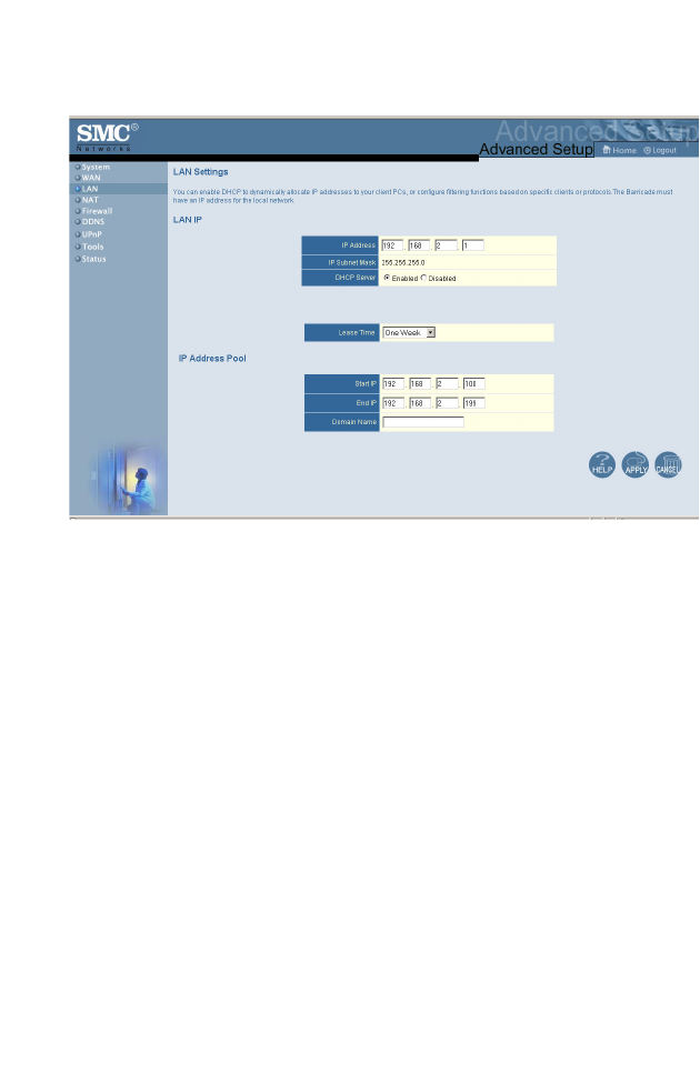
LAN
•LAN IP – Use the LAN menu to configure the LAN IP address
for the Wireless Barricade and to enable the DHCP server for
dynamic client address allocation.
•Set a period for the lease time if required. For home networks
this may be set to Forever, which means there is no time limit
on the IP address lease.
•IP Address Pool – A dynamic IP start address may be
specified by the user, e.g. 192.168.2.100 (default value).
Once this start IP address has been assigned, IP addresses
running from 192.168.2.100 to 192.168.2.199 will be part of
the dynamic IP address pool. IP addresses from 192.168.2.2
to 192.168.2.99, and 192.168.2.200 to 192.168.2.254 will be
available as static IP addresses.
Remember not to include the address of the Wireless Barricade
in the client address pool. Also remember to configure your client
PCs for dynamic IP address allocation.
Configuring the Wireless Barricade
44
Wireless Settings (Wireless)
To configure the Wireless Barricade as a wireless access point
for wireless clients (either stationary or roaming), all you need to
do is define the service set identifier (ESSID), the rates of
transmission of data and of commands, the radio channel, and
the encryption options. Note that the radio channel and the
service set identifier must be set to the same value for the
Wireless Barricade and for all wireless clients.
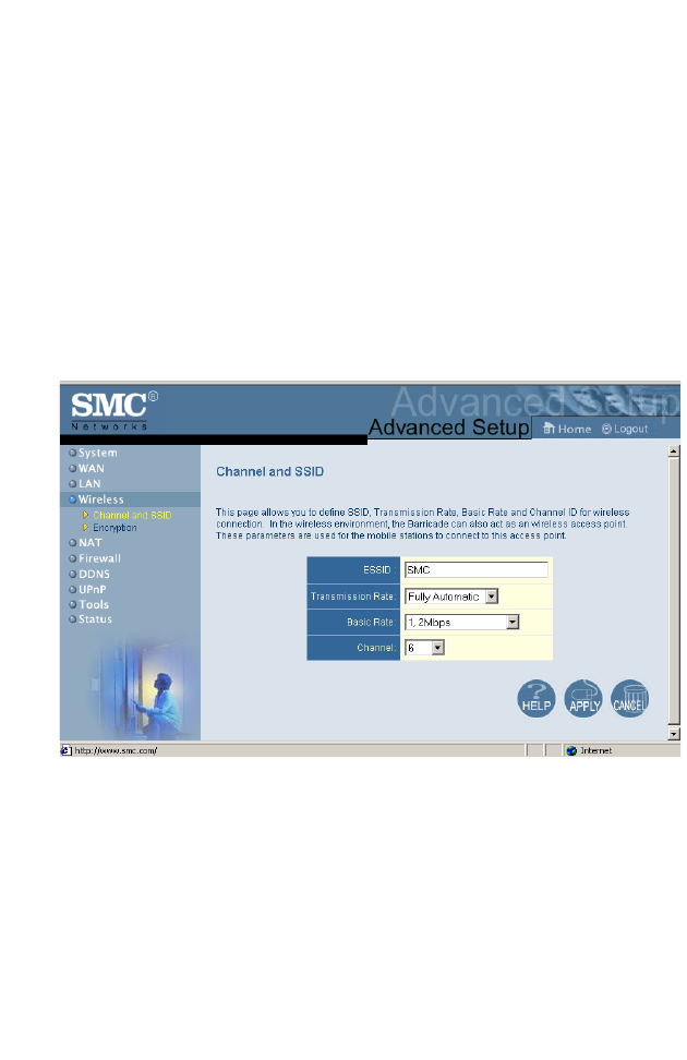
Channel and SSID
ESSID – The Extended Service Set Identifier for the wireless
network. Also known as the wireless service domain.
Transmission Rate – The rate of transmission of data, the
selections from the drop-down menu are: Fully Automatic,
11 Mbps, Automatic 1 or 2 Mbps, 2 Mbps, or 1 Mbps.
Advanced Setup
45
If set to Fully Automatic, the data rate will be automatically
selected. If set to Automatic 1 to 2 Mbps the data rate will
automatically be selected between these values. If manually set
to a specific value then the data rate is fixed at that value.
Basic Rate – The rate of transmission of commands.
Channel – The radio channel.
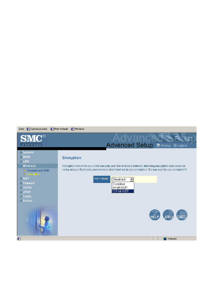
Encryption
If you are transmitting sensitive data across wireless channels,
you should enable encryption.
Encryption requires you to use the same set of encryption/
decryption keys for the Wireless Barricade and your wireless
clients. You can choose between standard 64-bit or the more
robust 128-bit encryption keys. However, please be aware that
the extra processing time required for encryption may affect the
throughput for wireless communications.
Configuring the Wireless Barricade
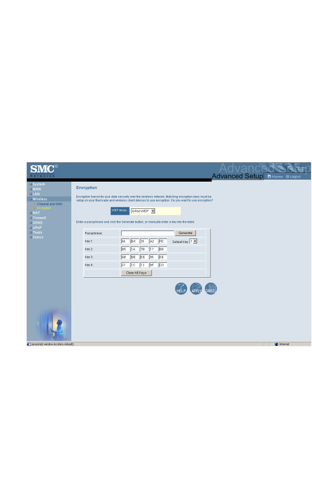
46
You can automatically generate encryption keys or you can
manually enter the keys. For automatic 64-bit security, you enter
a passphrase that is used to create four keys and click Generate
(as shown below). A passphrase may consist of up to 32
alphanumeric digits. The automatic 128-bit security generates a
single key by entering a passphrase. To manually configure the
keys, enter five hexadecimal pairs for each 64-bit key, or enter 13
pairs for the single 128-bit key. (A hexadecimal digit is a number
or letter in the range 0-9 or A-F.)
Network Address Translation (NAT)
From this section you can configure the Address Mapping, Virtual
Server, and Special Application features that provide control over
the port openings in the router’s firewall. This section can be
used to support several Internet based applications such as VPN
Advanced Setup
47
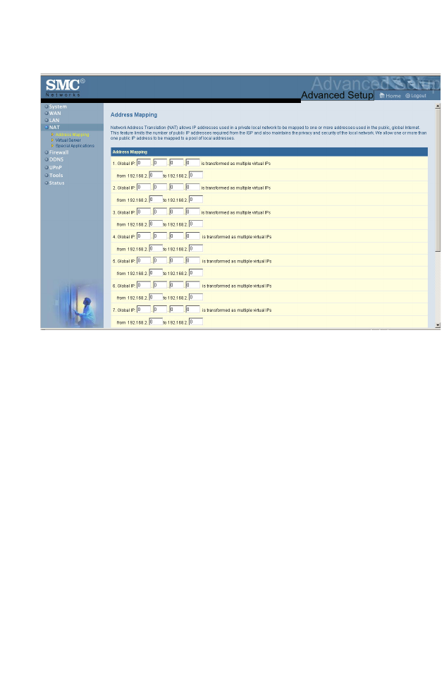
Address Mapping
Allows one or more public IP addresses to be shared by multiple
internal users. Enter the Public IP address you wish to share into
the Global IP field. Enter a range of internal IPs that will share the
global IP.
Configuring the Wireless Barricade
48
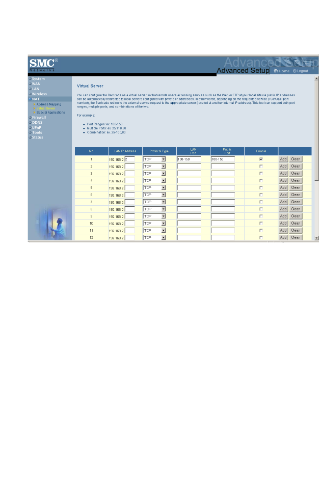
Virtual Server
If you configure the Wireless Barricade as a virtual server,
remote users accessing services such as Web or FTP at your
local site via public IP addresses can be automatically redirected
to local servers configured with private IP addresses (LAN IP
Addresses). In other words, depending on the requested service
(TCP/UDP port number), the Wireless Barricade redirects the
external service request to the appropriate server (located at
another internal IP address).
For example, if you set Protocol Type /Public Port to TCP/80
(HTTP or Web) and the LAN IP Address/LAN Port to
192.168.2.2/80, then all HTTP requests from outside users will
be transferred to 192.168.2.2 on port 80. Therefore, by just
entering the IP Address provided by the ISP, Internet users can
access the service they need at the local address to which you
redirect them.
Advanced Setup
49
The more common TCP service ports include:
HTTP: 80, FTP: 21, Telnet: 23, and POP3: 110.
Note: This tool can support both port ranges, multiple ports,
and combinations of the two.
For example:
Port Ranges:100-150
Multiple Ports: 25,110,80
Combination: 25-50,80
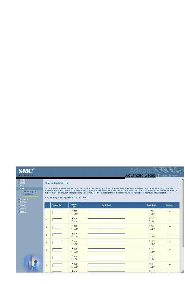
Special Applications
Some applications, such as Internet gaming, videoconferencing,
Internet telephony and others, require multiple connections.
These applications cannot work with Network Address
Translation (NAT) enabled. If you need to run applications that
require multiple connections, use the following screen to specify
the additional public ports to be opened for each application.

Configuring the Wireless Barricade
50
Specify the public port number normally associated with an
application in the Trigger Port field. Set the protocol type to TCP
or UDP, then enter the ports that the application requires. The
ports may be in the format 7, 11, 57, or in a range, e.g., 72-96, or
a combination of both, e.g., 7, 11, 57, 72-96.
Popular applications requiring multiple ports are listed in the
Popular Applications field. From the drop-down list, choose the
application and then choose a row number to copy this data into.
Note: Choosing a row that already contains data will
overwrite the current settings.
For a full list of ports and the services that run on them, see
www.iana.org/assignments/port-numbers.
Firewall
The Wireless Barricade firewall can provide access control of
connected client PCs, block common hacker attacks, including IP
Spoofing, Land Attack, Ping of Death, IP with zero length, Smurf
Attack, UDP port loopback, Snork Attack, TCP null scan, and
TCP SYN flooding. The firewall does not significantly affect
system performance, so we advise leaving it enabled to protect
your network users. To access the firewall menu, select Enable
and click on Apply.
Advanced Setup
51
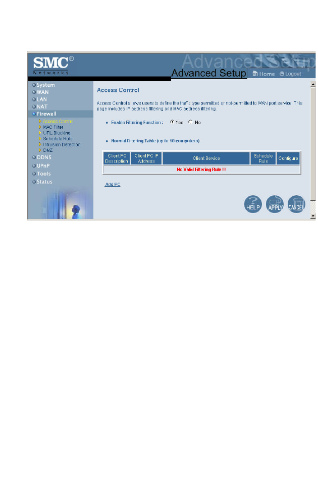
Access Control
Using this option allows you to specify different privileges based
on IP address for the client PCs.
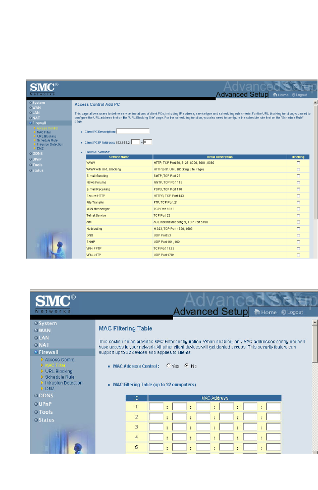
Configuring the Wireless Barricade
52
Note: Click on Add PC and define the appropriate settings for
client PC services (as shown in the following screen).
MAC Filtering Table