Accton Technology 7004ACC Barricade 2.4GHz 11Mbps Wireless Cable/DSL Router User Manual SMC7004AWBRV2
Accton Technology Corp Barricade 2.4GHz 11Mbps Wireless Cable/DSL Router SMC7004AWBRV2
Contents
- 1. User Manual Part 1
- 2. User Manual Part 2
User Manual Part 2
Advanced Setup
53
The MAC Filtering feature of the Wireless Barricade allows you to
control access to your network to up to 32 clients based on the
MAC (Media Access Control) Address of the client machine. This
ID is unique to each network adapter. If the MAC address is
listed in the table, that client machine will have access to the
network.
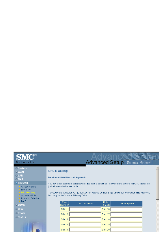
URL Blocking
To configure the URL Blocking feature, use the table below to
specify the websites (www.somesite.com) and/or keywords you
want to filter on your network.
To complete this configuration, you will need to create or modify
an access rule in “Access Control” on page 51. To modify an
existing rule, click the Edit option next to the rule you want to
modify. To create a new rule, click on the Add PC option.
From the Access Control Add PC section check the option for
WWW with URL Blocking in the Client PC Service table to filter
out the websites and keywords specified below.
Configuring the Wireless Barricade
54
Use the above screen to block access to Web sites or to Web
URLs containing the keyword specified in the table.
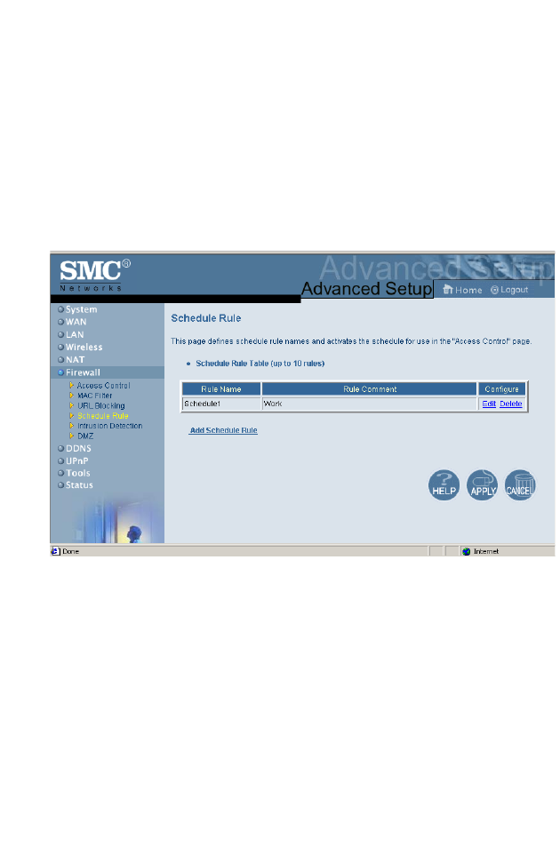
Schedule Rule
The Schedule Rule feature allows you to configure specific rules
based on Time and Date. These rules can then be used to
configure more specific Access Control.
Enables Schedule-based Internet access control.
1. Click Add Schedule Rule.
2. Define the settings for the schedule rule (as shown on the
following screen).
Advanced Setup
55
3. Click OK and then click the APPLY button to save your
settings.
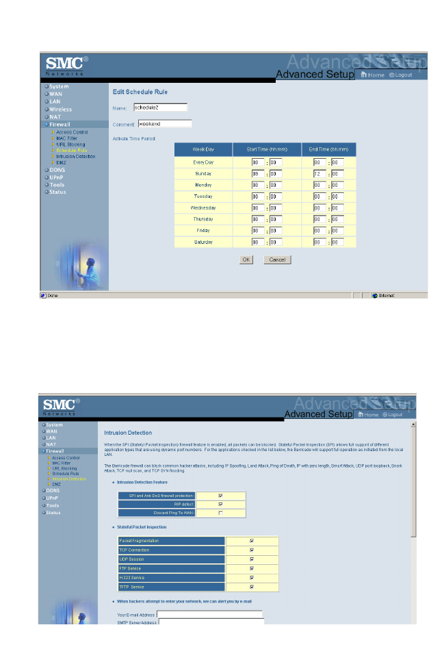
Intrusion Detection
Configuring the Wireless Barricade
56
•SPI and Anti-DoS firewall protection (Default: Enabled)
–The Wireless Barricade Intrusion Detection Feature limits
access for incoming traffic at the WAN port. When the SPI
feature is turned on, all incoming packets will be blocked
except for those types marked with a check in the Stateful
Packet Inspection section.
•RIP Defect (Default: Enabled) – If an RIP request packet is
not replied to by the router, it will stay in the input queue and
not be released. Accumulated packets could cause the input
queue to fill, causing severe problems for all protocols.
Enabling this feature prevents the packets accumulating.
•Discard Ping from WAN (Default: Disabled)
– Prevents a PING on the Gateway’s WAN port from being
routed to the network.

Advanced Setup
57
•Stateful Packet Inspection – This is called a “stateful” packet
inspection because it examines the contents of the packet to
determine the state of the communications; i.e., it ensures that
the stated destination computer has previously requested the
current communication. This is a way of ensuring that all
communications are initiated by the recipient computer and
are taking place only with sources that are known and trusted
from previous interactions. In addition to being more rigorous
in their inspection of packets, stateful inspection firewalls also
close off ports until connection to the specific port is
requested.
When particular types of traffic are checked, only the
particular type of traffic initiated from the internal LAN will be
allowed. For example, if the user only checks FTP Service in
the Stateful Packet Inspection section, all incoming traffic will
be blocked except for FTP connections initiated from the local
LAN.
Stateful Packet Inspection allows you to select different
application types that are using dynamic port numbers. If you
wish to use the Stateful Packet Inspection (SPI) to block
packets, click on the Yes radio button in the “Enable SPI and
Anti-DoS firewall protection” field and then check the
inspection type that you need, such as Packet Fragmentation,
TCP Connection, UDP Session, FTP Service, H.323 Service,
and TFTP Service.
•When hackers attempt to enter your network, we can alert
you by e-mail – Enter your E-mail address. Specify your
SMTP and POP3 servers, user name, and password.

Configuring the Wireless Barricade
58
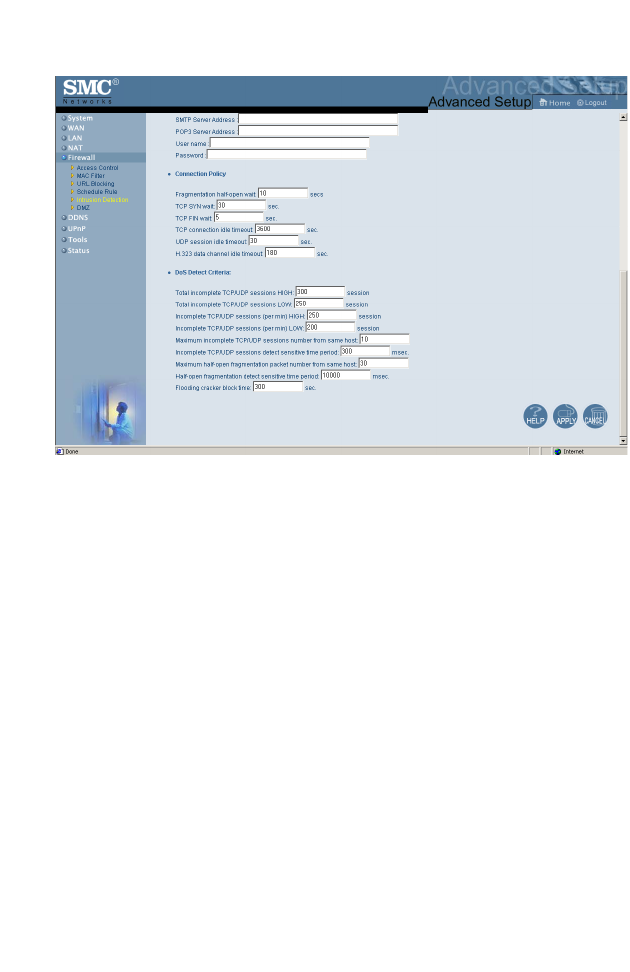
•Connection Policy – Enter the appropriate values for TCP/
UDP sessions as described in the following table.
Parameter Defaults Description
Fragmentation
half-open wait 10 sec Configures the number of seconds
that a packet state structure
remains active. When the timeout
value expires, the router drops the
unassembled packet, freeing that
structure for use by another packet.
TCP SYN wait 30 sec Defines how long the software will
wait for a TCP session to
synchronize before dropping the
session.
TCP FIN wait 5 sec Specifies how long a TCP session
will be maintained after the firewall
detects a FIN packet.
TCP connection
idle timeout 3600
seconds
(1 hour)
The length of time a TCP session
will be maintained if there is no
activity.
UDP session idle
timeout 30 sec The length of time a UDP session
will maintained if there is no activity.
H.323 data
channel idle
timeout
180 sec The length of time an H.323
session will be maintained if there
is no activity.

Advanced Setup
59
DoS Criteria and Port Scan Criteria
Set up DoS and port scan criteria in the spaces provided (as
shown below).
Parameter Defaults Description
Total incomplete TCP/
UDP sessions HIGH 300 sessions Defines the rate of newly
unestablished sessions that
will cause the software to
start deleting half-open
sessions.
Total incomplete TCP/
UDP sessions LOW 250 sessions Defines the rate of newly
unestablished sessions that
will cause the software to
stop deleting half-open
sessions.
Incomplete TCP/UDP
sessions (per min.) HIGH 250 sessions Maximum number of
allowed incomplete TCP/
UDP sessions per minute.
Incomplete TCP/UDP
sessions (per min.) LOW 200 sessions Minimum number of
allowed incomplete TCP/
UDP sessions per minute.
Set this to “0” if no minimum
setting is required.
Maximum incomplete
TCP/UDP sessions
number from same host
10 sessions Maximum number of
incomplete TCP/UDP
sessions from the same
host.
Incomplete TCP/UDP
sessions detect sensitive
time period
300 msec Length of time before an
incomplete TCP/UDP
session is detected as
incomplete.
Maximum half-open
fragmentation packet
number from same host
30 Maximum number of
half-open fragmentation
packets from the same
host.
Half-open fragmentation
detect sensitive time
period
1sec Length of time before a
half-open fragmentation
session is detected as
half-open.
Configuring the Wireless Barricade
60
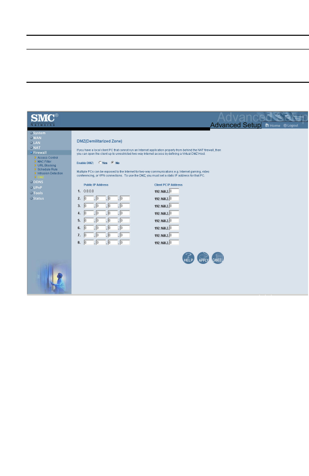
DMZ
If you have a client PC that cannot run an Internet application
properly from behind the firewall, then you can open the client up
to unrestricted two-way Internet access. Enter the IP address of
a DMZ host to this screen. Adding a client to the DMZ
(Demilitarized Zone) may expose your local network to a variety
of security risks, so only use this option as a last resort.
Flooding cracker block
time 300 sec Length of time from
detecting a flood attack to
blocking of the attack.
Parameter Defaults Description
Advanced Setup
61
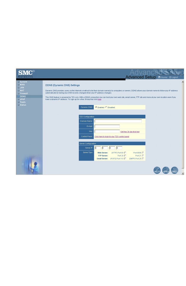
DDNS (Dynamic DNS) Settings
Dynamic DNS provides users on the Internet with a method to tie
their domain name(s) to computers or servers. DDNS allows your
domain name to follow your IP address automatically by having
your DNS records changed when your IP address changes.
Domain Name – A series of alphanumeric strings separated by
periods, that is the address of a the Wireless Barricade network
connection and that identifies the owner of the address.
The section also has a “Server Configuration” section that
automatically opens the port options checked in the Virtual
Server section. Simply enter in the IP Address of your server,
such as a web server, and then click on the port option HTTP
Port 80 so users can access your server from the WAN
connection (Internet).
Configuring the Wireless Barricade
62
This DNS feature is powered by TZO.com. With a DDNS
connection you can host your own web site, email server, FTP
site, and more at your own location even if you have a dynamic
IP address. (Default: Disable)
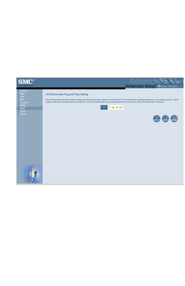
UPnP (Universal Plug and Play) Setting
Enable UPnP by checking ON in the screen above. UPnP allows
the device to automatically:
•dynamically join a network
•obtain an IP address
•convey its capabilities and learn about the presence and
capabilities of other devices.(Default: OFF)
Advanced Setup
63
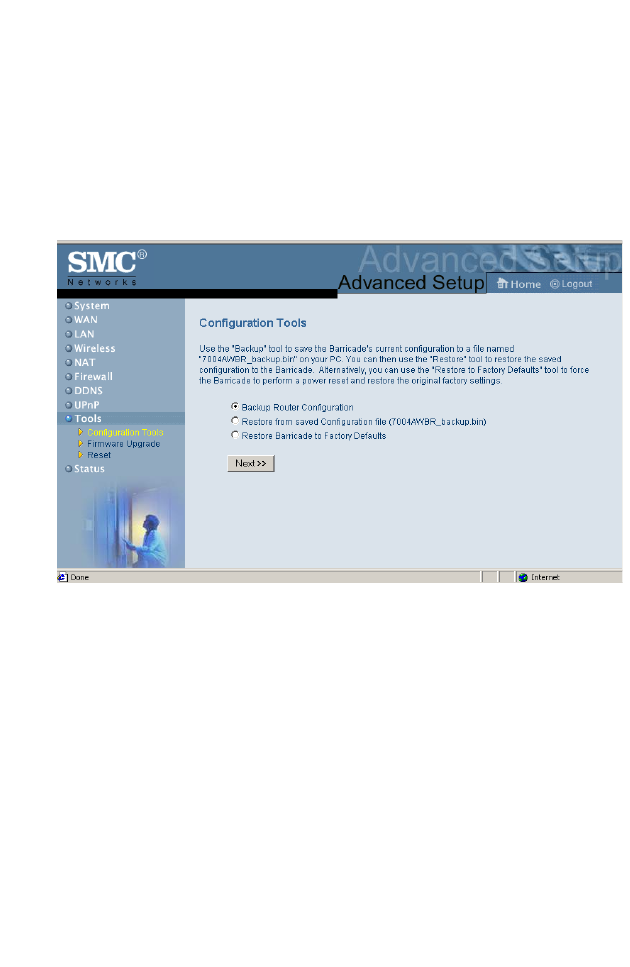
Tools
Use the Tools menu to backup the current configuration, restore
a previously saved configuration, restore factory settings, update
firmware, and reset the Wireless Barricade.
Tools - Configuration Tools
•Backup – saves the Wireless Barricade’s configuration to
a file.
•Restore – restores settings from a saved backup
configuration file.
•Restore to factory defaults – restores the Wireless
Barricade settings back to the factory default original.
Configuring the Wireless Barricade
64
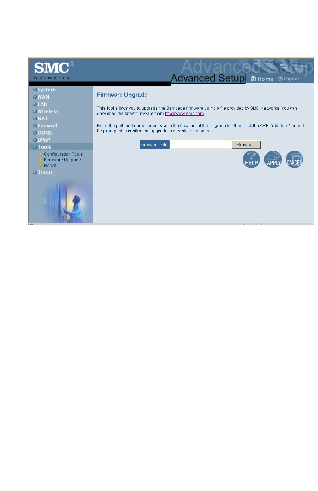
Tools - Firmware Upgrade
Use this screen to update the firmware or user interface to the
latest versions. Download the upgrade file from the SMC Web
site (www.smc.com) and save it to your hard drive.Click Browse
to look for the previously downloaded file. Click APPLY. Check
the Status page Information section to confirm that the upgrade
process was successful.
Advanced Setup
65
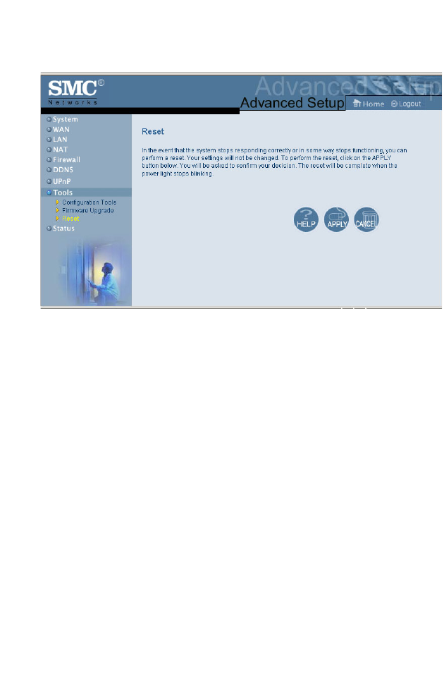
Tools - Reset
Click APPLY to reset the Wireless Barricade. The reset will be
complete when the power LED stops blinking.
Note: If you use the Reset button on the front panel, the
Wireless Barricade performs a power reset. If the
button is held depressed for over five seconds, all the
LEDs will illuminate and the factory settings will be
restored.
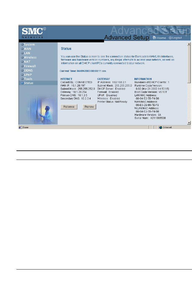
Status
The Status screen displays WAN/LAN connection status,
firmware, and hardware version numbers, illegal attempts to
access your network, as well as information on DHCP clients
connected to your network.
Configuring the Wireless Barricade
66
The following items are included on this screen:
Section Description
INTERNET Displays WAN connection type and status.
GATEWAY Displays system IP settings, as well as DHCP
and Firewall status.
INFORMATION Displays the number of attached clients, the
firmware versions, the physical MAC address
for each media interface, as well as the
hardware version and serial number.
Security Log Displays illegal attempts to access your
network.
Save Click on this button to save the security log file.
Clear Click on this button to delete the access log.
Refresh Click on this button to refresh the screen.
DHCP Client Log Displays information on all DHCP clients on
your network.

67
CONFIGURING THE PRINT
SERVER
If you want to use the print server built into the Wireless
Barricade, then you must first install the Port Monitor program as
described in the following section for Windows 95/98/Me/NT/
2000.
To configure the Wireless Barricade Print Server for Windows 95/
98/Me/NT/2000, or Unix, see “Configure the Print Server” on
page 70.
Install the SMC Printer Port Monitor
Skip this section if you are using Unix.
For Windows 95/98/Me/NT/2000 clients, you need to install the
port monitor program as described in this section.
1. Insert the installation CD-ROM into your CD-ROM drive.
Under the Print Server directory, run the setup.exe program.
The SMC Port Monitor installation program advises you to
close all other Windows programs currently running on your
computer. Click Next to continue.
Configuring the Print Server
68
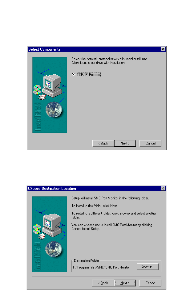
2. The next screen indicates that the print client uses TCP/IP
network protocol to monitor print requests. Click Next.
3. Select the destination folder and click on the Next button. The
setup program will then begin to install the programs into the
destination folder.
Install the SMC Printer Port Monitor
69
4. Select the Program Folder that will contain the program icon
for uninstalling the port monitor, and then click Next.
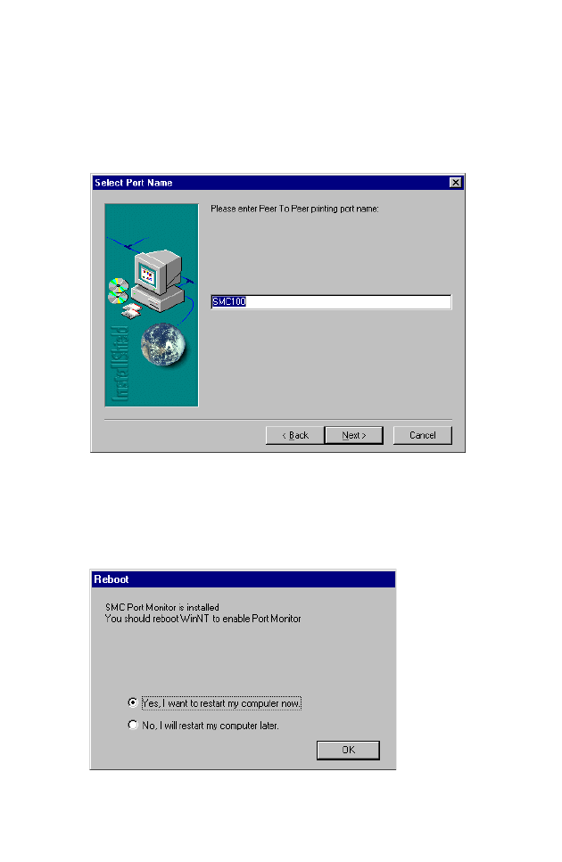
5. Enter the printer port name that will be used to identify the
port monitor in your system, and press Next.
6. When the setup program finishes installing the port monitor,
check the radio button to restart your computer and then click
OK.
7. After rebooting your computer, add the Wireless Barricade
print server to your system as described in the following
section.
Configuring the Print Server
70
Configure the Print Server
The Wireless Barricade’s print server supports Microsoft
Windows 95/98/Me/NT/2000, and Unix. If you are using Windows
95/98/Me/NT/2000, first install the port monitor as described in
the previous section before adding the Wireless Barricade’s print
server to your operating system.
Configure the Network Printer in Windows 95/98/Me/
2000
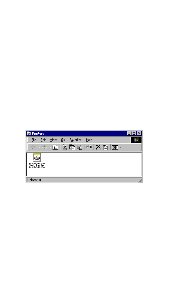
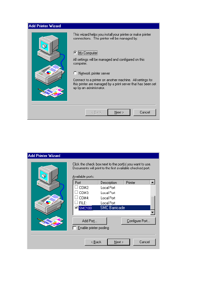
1. On a Windows 95/98/Me/2000 platform, open the Printers
window in
the My Computer menu, and double-click the Add
Printer icon.
Configure the Print Server
71
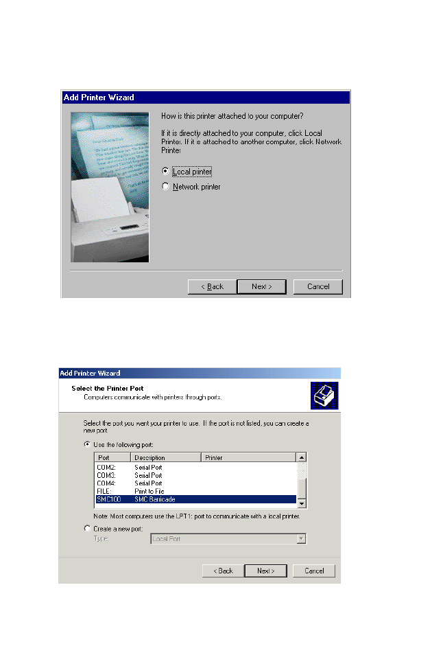
2. Follow the prompts to add a Local printer to your system.
Specify the printer type attached to the Wireless Barricade.
3. Select the monitored port (the default port name is SMC100)
and then click the Create a new port button.
Configuring the Print Server
72
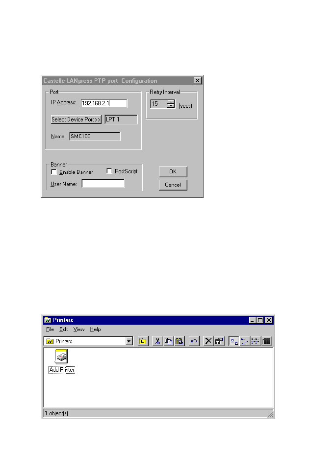
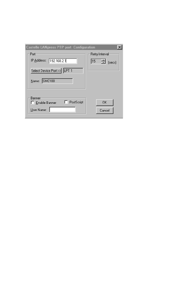
4. Enter the IP address of the Wireless Barricade and click OK,
and then click Next in the Add Printer Wizard dialog box.
5. Continue following the prompts to finish installing the Wireless
Barricade print server. The printer type you specified will now
be added to your Printers menu.
Configure the Network Printer in Windows NT
1. On a Windows NT platform, open the Printers window in
the
My Computer menu, and double-click the Add Printer icon.
2. Follow the prompts to add a local printer to your system.
Configure the Print Server
73
3. Select the monitored port. The default port name is SMC100.
Then click the Configure Port button.
Configuring the Print Server
74
4. Enter the IP address of the Wireless Barricade and click OK,
and then click Next in the Add Printer Wizard dialog box.
5. Specify the printer type attached to the Wireless Barricade.
6. Continue following the prompts to finish installing the Wireless
Barricade print server. The printer type you specified will now
be added to your Printers menu.
Configure the Network Printer in Unix Systems
Follow the traditional configuration procedure on Unix platforms
to set up the Wireless Barricade print server. The printer name is
lpt1.
Configure LPR port on Windows 2000/XP
The Wireless Barricade Printer function can also be used with
the LPR port on Windows XP and Windows 2000 machines.
Below is an outline on how to configure the LPR port on a
Windows 2000 machine; however the same steps will apply for a
Windows XP.
1. Open the Control Panel.
2. Click on the Printers and Faxes or Printers icon.
Configure the Print Server
75
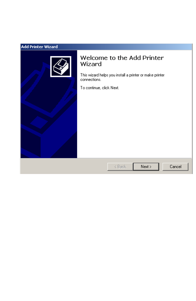
3. Click on the Add Printer icon to launch the Add Printer
Wizard.
4. Click Next button to begin the printer installation process.
5. On the next dialog box, choose the Local Printer option and
verify the “Automatically detect and install my Plug and Play
printer” option is unchecked.
Note: On Windows XP check the “Local printer attached to
this computer.”
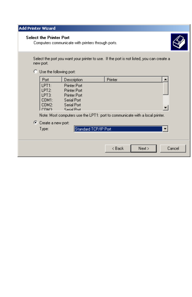
6. Click the Next button to create a new printer port.
7. Select the Create a New Port option and then select the
Standard TCP/IP Port option in the drop down menu.
Configuring the Print Server
76
Configure the Print Server
77
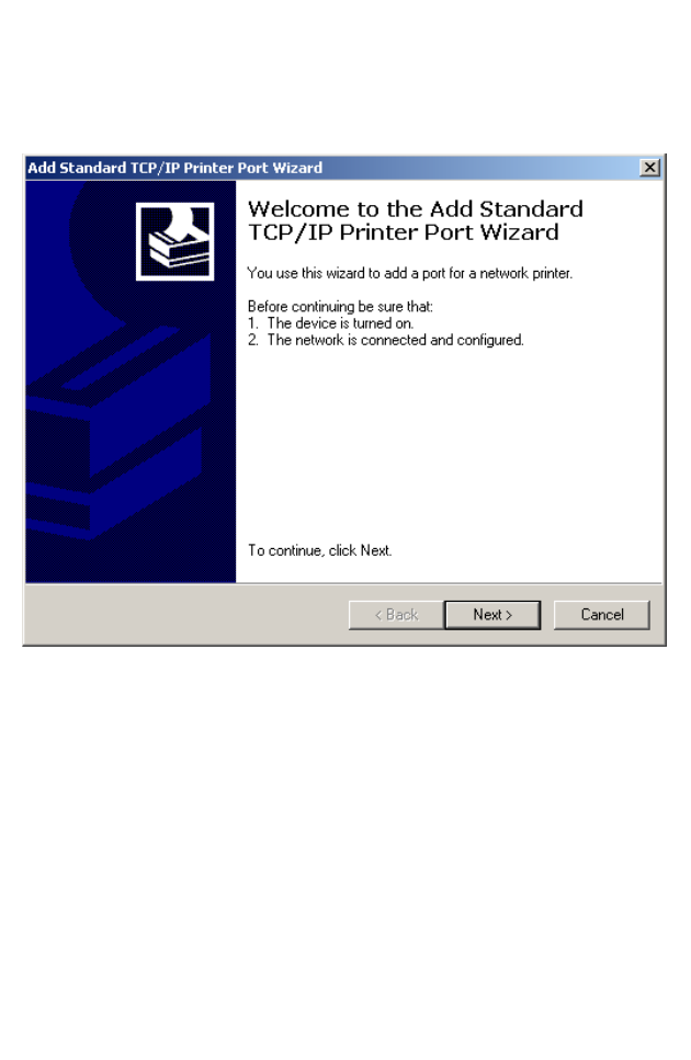
8. When you click the Next button the “Add Standard TCP/IP
Printer Port Wizard” will launch.
9. To start this new installation wizard click the Next button.
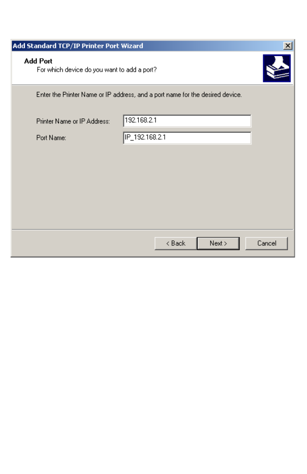
10. Provide the appropriate IP and Port name information for your
new Printer port. If you are using default settings on the router
you can use the following information:
Printer Name or IP Address: 192.168.2.1 Port Name:
IP_192.168.2.
Note: This is the IP that you use to administer your router
with (for example: 192.168.2.1). If you have changed
this IP address then please use the new one that you
have assigned to your router.
Configuring the Print Server
78
11. Click the Next button to continue
12. On the next dialog box, under the Device type choose the
Custom option
13. Then click the Settings… button to input the Specific Wireless
Barricade Printer port information.
Configure the Print Server
79
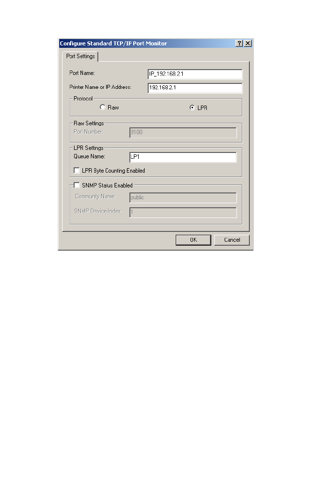
14. In the Configure Standard TCP/IP Port Monitor dialog box you
will need to configure some additional settings. Please
confirm these settings below:
•Port Name: IP_192.168.2.1*
•Printer Name or IP Address: 192.168.2.1*
* This should be the same information that was configured in
Step 7.
•In the Protocol section click on the LPR option
•The Raw Settings section should be grayed out
•The LPR Settings section should have the Queue Name set to
one of 2 options depending on the version of Wireless
Barricade you are using.

Configuring the Print Server
80
•The Queue Name is LPT1.
•Verify the LPR Byte Counting Enabled and SNMP Status
Enabled options are unchecked.
15. Once you have verified all of these settings, click the OK
button to save these settings and close the “Configure
Standard TCP/IP Port Monitor” window.
16. Click Next to continue and view a summary of the
configuration that you have just completed.
17. Click the Finish button to complete the configuration process
of the TCP/IP port
18. The Add Printer Wizard will now guide you through the Printer
Driver installation for the LPR port you just installed.
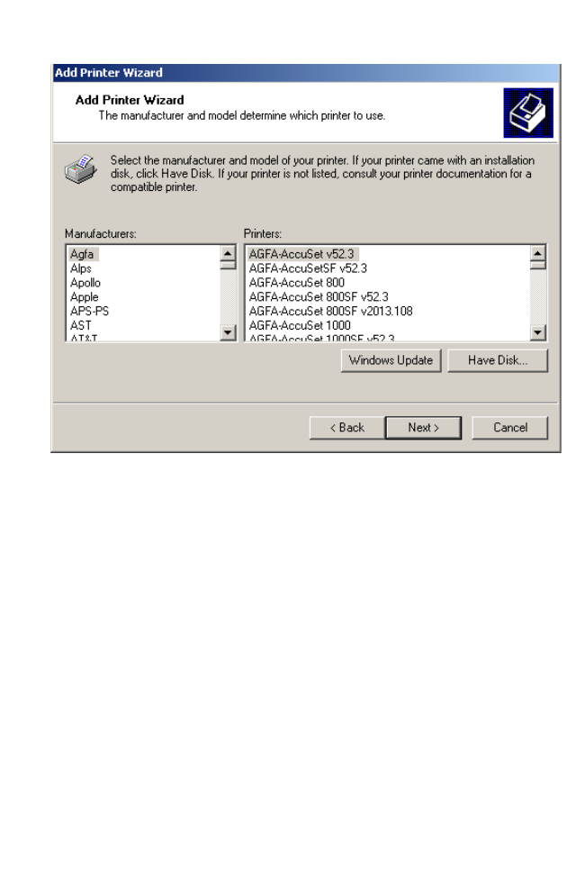
19. In the dialog box listed below, choose the manufacturer of the
printer that you have, and then choose your model of printer.
If your printer is not listed here, then please refer to your
printer documentation to get your printer installed.
Configure the Print Server
81
20. Once you have your printer listed and selected in this dialog
box click the Next button.
Configuring the Print Server
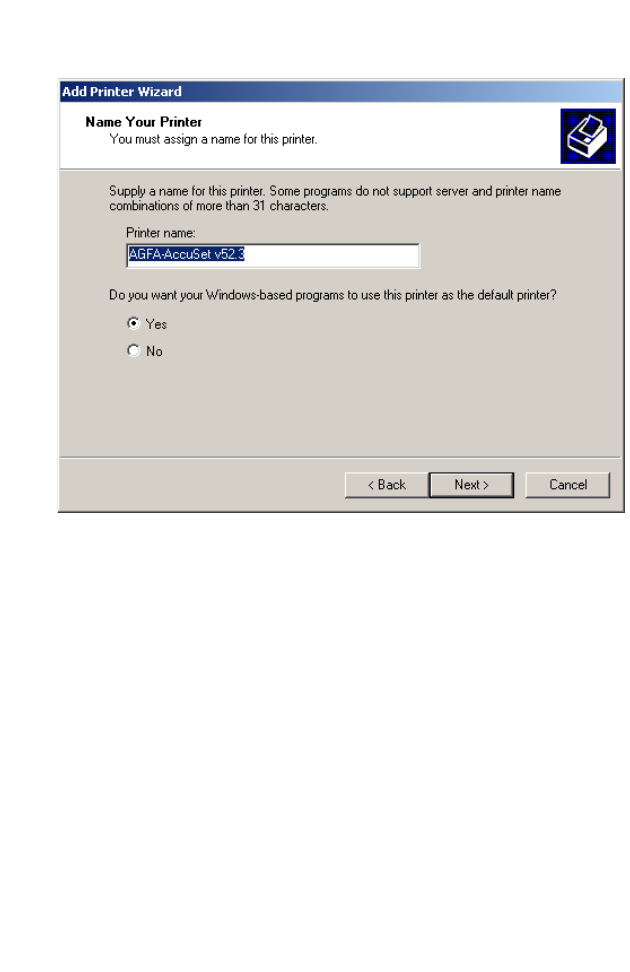
82
21. Name your printer. In this dialog box you will give your
installed printer a name; this will be the name this printer is
referred to in your Printer folder.
22. Once you have named your printer, click Next to continue.
23. Choose the Do not share this printer option and click the Next
button.
24. Choose No to the Print Test Page option, and click the Next
button.
25. On the next screen, you should now see a dialog box with a
summary of all the printer information that you have just
configured. To complete the installation, click the Finish
button.
Configure the Print Server
83
Once you have completed the printer installation, you will need
to configure some properties on your printer. To do so, please
follow the steps listed below:
1. If you closed out the Printers window, please re-open it from
the control panel.
2. Locate the printer that you just installed and right-mouse click
on it and choose Properties.
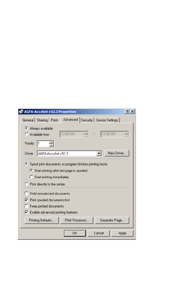
3. Click on the Advanced tab and verify the following settings:
•Both the “Spool print documents so program finishes printing
faster” and the “Start printing after last page is spooled”
options are selected.
•Both the “Print spooled documents first” and “Enable
advanced printing features” options are checked.
Configuring the Print Server
84
•All of the other options should be disabled or unchecked.
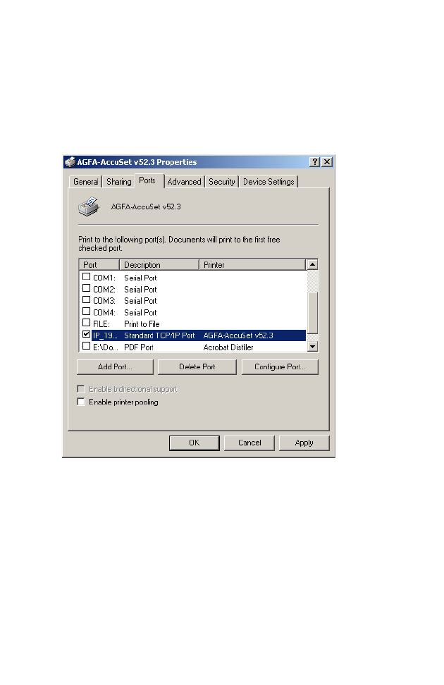
4. Click on the Ports tab and verify that you have the TCP/IP port
that you just created selected and the Enable bidirectional
support and Enable printer pooling options are unchecked.
5. Click the Apply button to save the settings.
6. Next click on the General tab and click on the Print Test Page
button. This will verify that you have successfully setup your
LPR printing port, and now you can print through the SMC
Wireless Barricade.

Configure the Print Server
85
Confirm printer connection
On the status page of the web-based login, you can confirm the
printer connection to the Wireless Barricade.
OK

86
TROUBLESHOOTING
The information outlined in this section describes some useful
steps for getting your computer and Wireless Barricade online.
The information outlined in this section describes common
problems you may encounter and possible solutions to them. The
Wireless Barricade can be easily monitored through panel
indicators to identify problems. If you cannot resolve any
connection problems after checking the indicators, then refer to
the other sections in the following table.

Troubleshooting
87
Troubleshooting Chart
Symptom Action
LED Indicators
Power LED is Off •External power supply has failed or
is disconnected.
•Check connections between the
Wireless Barricade, the external
power supply, and the wall outlet.
•If the power indicator does not turn
on when the power cord is plugged
in, you may have a problem with the
power outlet, power cord, or external
power supply.
•If the unit powers off after running for
a while, check for loose power
connections, power losses or surges
at the power outlet.
•If you cannot isolate the problem,
then the external power supply may
be defective. In this case, contact
SMC Technical Support for
assistance.

Troubleshooting
88
LED Indicators
Link LED is Off •Verify that the Wireless Barricade
and attached device are powered
on.
•Be sure the cable is plugged into
both the Wireless Barricade and the
corresponding device.
•Verify that the proper cable type is
used and its length does not exceed
specified limits.
•Be sure that the network interface
on the attached device is configured
for the proper communication speed
and duplex mode.
•Check the adapter on the attached
device and cable connections for
possible defects. Replace any
defective adapter or cable if
necessary.
Troubleshooting Chart
Symptom Action

Troubleshooting
89
Network Connection Problems
Cannot Ping the
Wireless Barricade
from the attached
LAN, or the Wireless
Barricade cannot
Ping any device on
the attached LAN
•Verify that IP addresses are properly
configured. For most applications,
you should use the Wireless
Barricade’s DHCP function to
dynamically assign IP addresses to
any host on the attached LAN.
However, if you manually configure
any IP addresses on the LAN, verify
that the same network address
(network component of the IP
address) and subnet mask are used
for both the Wireless Barricade and
attached LAN devices.
•Be sure the device you want to ping
(or from which you are pinging) has
been configured for TCP/IP.
Mobile users cannot
access the Wireless
Barricade
•Make sure that the Wireless
Barricade and all mobile users are
configured to use the same radio
channel, wireless domain (SSID),
and encryption keys.
•Ensure that all mobile users are
within range of the Wireless
Barricade as specified in
Appendix C.
Troubleshooting Chart
Symptom Action

Troubleshooting
90
Management Problems
Cannot connect using
the Web browser •Be sure you have configured the
Wireless Barricade with a valid IP
address, subnet mask, and default
gateway.
•Check that you have a valid network
connection to the Wireless
Barricade and that the port you are
using has not been disabled.
•Check network cabling between the
management station and the
Wireless Barricade.
Forgot or lost the
password •Press the “Reset” button for at least
five seconds on the rear panel to
restore the factory defaults.
Printer Server
The printer cannot
print or prints garbage •Make sure the parallel cable
between the Wireless Barricade and
printer is connected and is in good
condition
Troubleshooting Chart
Symptom Action

Troubleshooting
91

92
SPECIFICATIONS
Below is an outline of the Technical Specifications for the
Barricade 2.4GHz 11 Mbps Wireless Cable/DSL Broadband
Router (SMC7004AWBR)
Standards
IEEE 802.3 10BASE-T Ethernet
IEEE 802.3u 100BASE-TX Fast Ethernet
IEEE 802.11b
LAN Interface
3 - RJ-45 10/100 Mbps Auto MDI/MDI-X ports
WAN Interface
1- RJ-45 10/100 Mbps Auto MDI/MDI-X port
Serial, 1 RS-232 DB-9 connector
WLAN Interface
Standard: IEEE 802.11b, Direct Sequence Spread Spectrum
(DSSS)
Transmission Rate: 11 Mbps, automatic fallback to 5.5, 2 or
1 Mbps
Maximum Channels: US/Canada: 11, Europe (ETSI): 13
Range: Up to 304 m (1000 ft)
Frequency: (US/Canada/Europe) 2.400-2.4835 GHz
,
Japan: 2.471-2.497 GHz
Sensitivity: 1, 2, 5.5 Mbps: -80 dBm; 11 Mbps: -76 dBm typical
Modulation: CCK, BPSK, QPSK
Encryption: 64-bit/128-bit WEP
Maximum Clients: 128
Printer Interface
Parallel
1 DB-25 printer port
Management
Web management

Specifications
93
Advanced Features
Dynamic IP Address Configuration – DHCP, DNS
Firewall – Client privileges, hacker prevention and logging
Virtual Private Network – PPTP, L2TP, IPSec pass-through
Backup Internet Connection –
Dial-on-demand via secondary WAN port
Printer server
Indicator Panel
Power
WAN: Link/Activity
LAN: Link/Activity, 10/100 (Mbps)
WLAN
Temperature
Operating: 0 to 40 °C (32 to 104 °F)
Storage: -20 to 70 °C (-4 to 158 °F)
Dimensions
21.91 x 13.34 x 2.54 cm (8.63 x 5.25 x 1 in.)
Weight
0.68 kg (1.5 lbs)
Input Power
9 V DC (1.0 A)
Maximum Current
0.40 A RMS max.@110 V, 0.87 A RMS max.@240 V
Power Consumption
10 Watts max. @ 100-240 VAC
Heat Dissipation
34.1 BTU/hr max. @ 100-240 VAC
Internet Standards
ARP (RFC 826), IP (RFC 791), ICMP (RFC 792), UDP (RFC
768), TCP (RFC 793), Telnet (RFC 854-859), MD5 (RFC 1321),

Specifications
94
BOOTP Extension (RFC 1497), PPP LCP Extension (RFC 1570),
PPPoE (RFC 2516), NAT (RFC 1631), PPP (RFC 1661), HTML
(RFC 1866), HTTP (RFC 1945), CHAP (RFC 1944), DHCP (RFC
2131), PPTP (RFC 2637)
Temperature
Operating (0 to 40 °C), 32 to 104 °F
Storage (- 40 to 70 °C), - 40 to 158 °F
Humidity
5% to 95% (noncondensing)
Compliances
CE Mark
Emissions
FCC Class B
Industry Canada Class B
EN55022 (CISPR 22) Class B
C-Tick - AS/NZS 3548 (1995) Class B
ETS 300 328
MPT RCR STD-33
Immunity
EN 61000-3-2/3
EN 61000-4-2/3/4/5/6/8/11
Safety
UL 1950
EN60950 (TÜV)
CSA 22.2 No. 950

38 Tesla
Irvine, CA 92618
Phone: (949) 679-8000
SMC7004AWBR
Part Number: 01-111234-001
Revision Number E042003-R01 F 1.0
FOR TECHNICAL SUPPORT, CALL:
From U.S.A. and Canada (24 hours a day, 7 days a week)
(800) SMC-4-YOU; (949) 679-8000; Fax: (949) 679-1481
From Europe (8:00 AM - 5:30 PM UK Time)
44 (0) 118 974 8700; Fax: 44 (0) 118 974 8701
INTERNET
E-mail addresses:
techsupport@smc.com
european.techsupport@smc-europe.com
support@smc-asia.com
Driver updates:
http://www.smc.com/index.cfm?action=tech_support_drivers_downloads
World Wide Web:
http://www.smc.com
http://www.smc-europe.com
http://www.smc-asia.com
FOR LITERATURE OR ADVERTISING RESPONSE, CALL:
U.S.A. and Canada: (800) SMC-4-YOU; Fax (949) 679-1481
Spain: 34-93-477-4935; Fax 34-93-477-3774
UK: 44 (0) 1932 866553; Fax 44 (0) 118 974 8701
France: 33 (0) 41 38 32 32; Fax 33 (0) 41 38 01 58
Italy: 39 (0) 335 5708602; Fax 39 02 739 14 17
Benelux: 31 33 455 72 88; Fax 31 33 455 73 30
Central Europe: 49 (0) 89 92861-0; Fax 49 (0) 89 92861-230
Nordic: 46 (0) 868 70700; Fax 46 (0) 887 62 62
Eastern Europe: 34 -93-477-4920; Fax 34 93 477 3774
Sub Saharian Africa: 27 0126610232; Fax 27-11 314 9133
North West Africa: 216 71236616; Fax 216 71751415
CIS: 7 (095) 789 35 73; Fax 7 (095) 789 35 73
PRC (Beijing): 86-10-8251-1550; Fax 86-10-8251-1551
PRC (Shanghai): 86-21-6485-9922; Fax 86-21-6495-7924
Taiwan: 886-2-8797-8006; Fax 886-2-8797-6288
Asia Pacific: (65) 6 238 6556; Fax (65) 6 238 6466
Korea: 82-2-553-0860; Fax 82-2-553-7202
Japan: 81-3-5645-5715; Fax 81-3-5645-5716
Australia: 61-2-8875-7887; Fax 61-2-8875-7777
India: 91 22 5696 2790; Fax 91 22 5696 2794