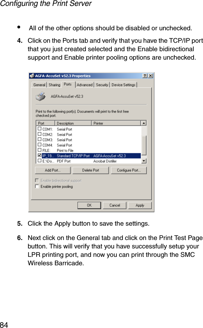
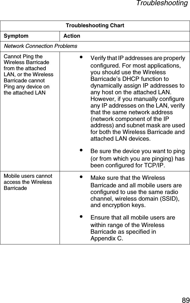
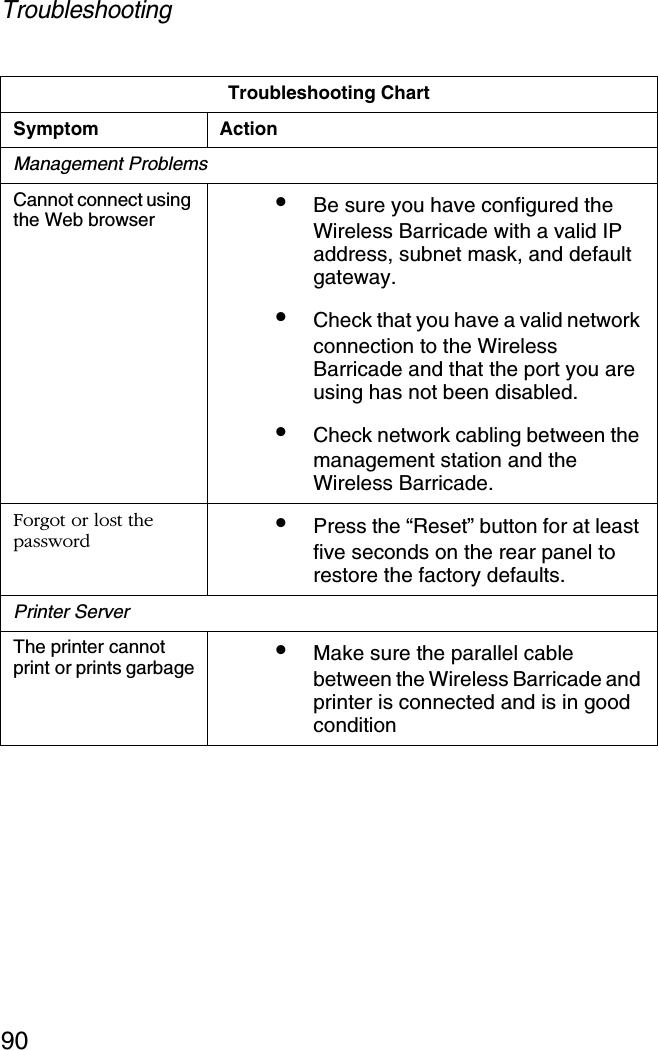
Accton Technology 7004ACC Barricade 2.4GHz 11Mbps Wireless Cable/DSL Router User Manual SMC7004AWBRV2
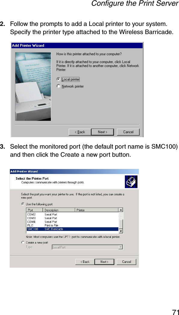
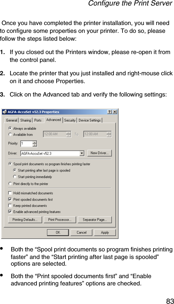
Accton Technology Corp Barricade 2.4GHz 11Mbps Wireless Cable/DSL Router SMC7004AWBRV2
Contents
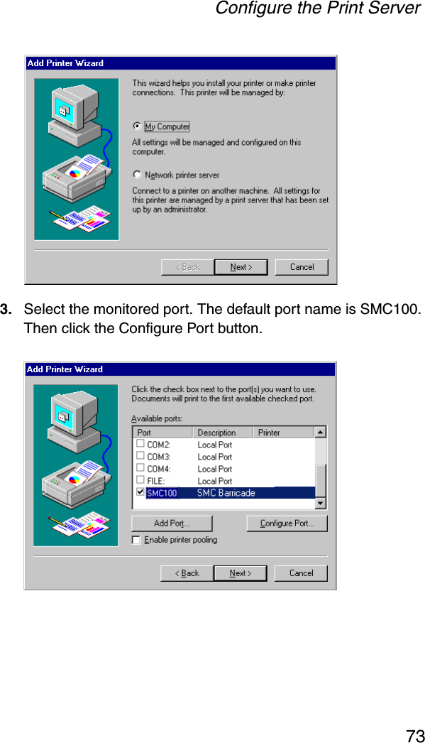
- 1. User Manual Part 1
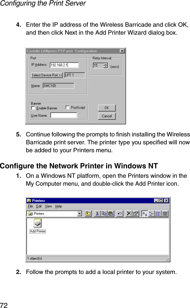
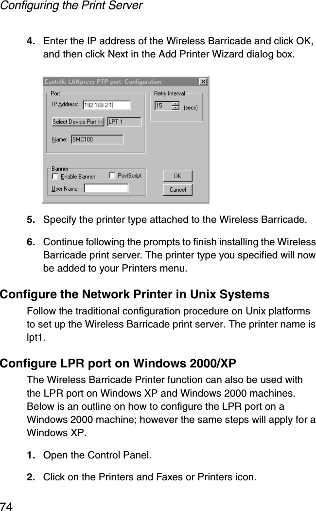
- 2. User Manual Part 2
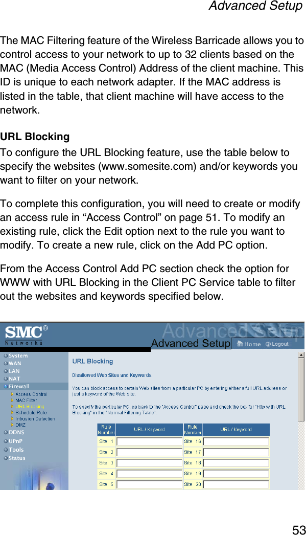
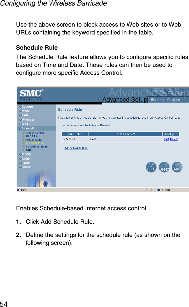
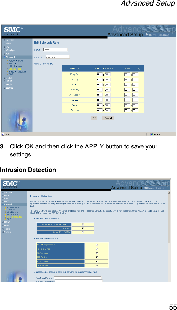
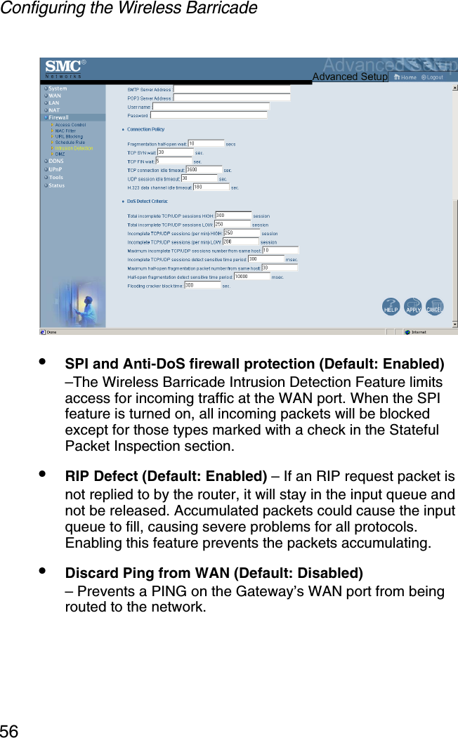
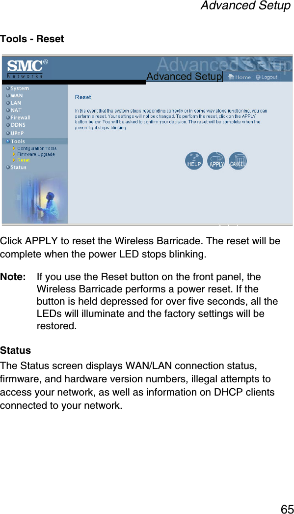
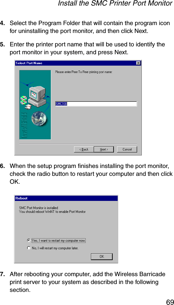
User Manual Part 2