Acroprint Time Recorder 1011 ENTRY CONTROL BADGE READER User Manual Micro computer Electronic Time Clock
Acroprint Time Recorder Company ENTRY CONTROL BADGE READER Micro computer Electronic Time Clock
Contents
- 1. USERS MANUAL 1 OF 4
- 2. USERS MANUAL 2 OF 4
- 3. USERS MANUAL 3 OF 4
- 4. USERS MANUAL 4 OF 4
USERS MANUAL 3 OF 4
NOTE
s
See Page 24 for USB to RS-232 Adaptor.
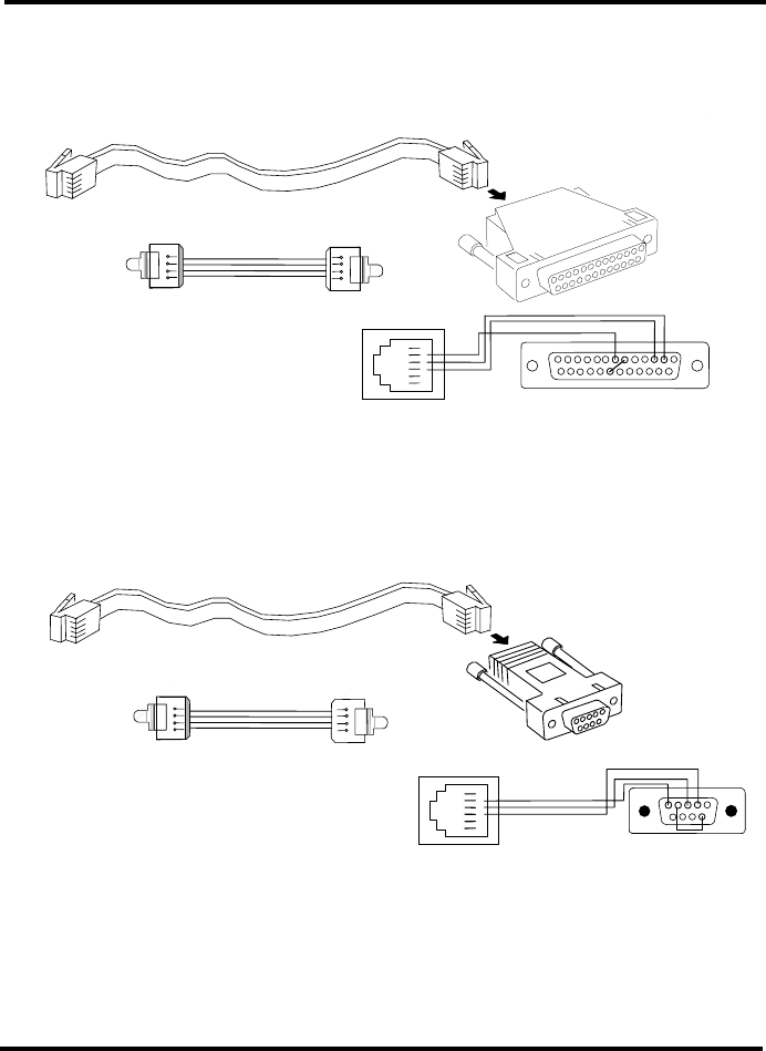
: Schematic connections are
hown from END VIEW (as viewed
from the outside of the connectors). Schematic
“Standard” Modular Cable
(Adaptor A)
DB-9 to RJ-11 Adaptor
(Use DB-25 RS-232 Host Cable Assy. See pp. 24-25)
Cabling to Host Computer with DB-9 Port
Schematic
NOTE: Schematic connections are
shown from END VIEW (as viewed
from the outside of the connectors).
(Use DB-25 RS-232 Host Cable Assy. See pp. 24-25)
Cabling to Host Computer with DB-25 Port
Schematic
Schematic
(Adaptor A)
DB-25 to RJ-11 Adaptor
14
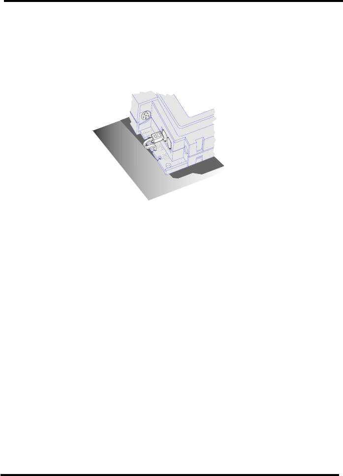
Local Area Network: RS-485 Serial Port
The RS-485 serial port is located on the lower left corner of the
terminal. It is a six position 6-pin female port with the outer 2 pins to
Ground. It will accept a male RJ-11 modular connector.
The terminal can use RS-485 2-wire serial communication, allowing up
to 32 terminals to be connected to one host port. An RS-232 port on the
host is typically used in conjunction with an RS-232/RS-485 converter
to complete the connection.
Through software, the host can communicate with individual terminals
even though they are wired in parallel. RS-485 communication uses a
differential bus, which provides good protection from interference over
long runs of up to 4000 feet.
NOTE: When wiring a network, always follow the electric wiring
codes in your area. Typically, a Teflon coated wire is required for
wiring through the ceiling. The “Daisy Chain” cabling between
junction boxes shown on the opposite page is a Teflon jacketed cable.
15
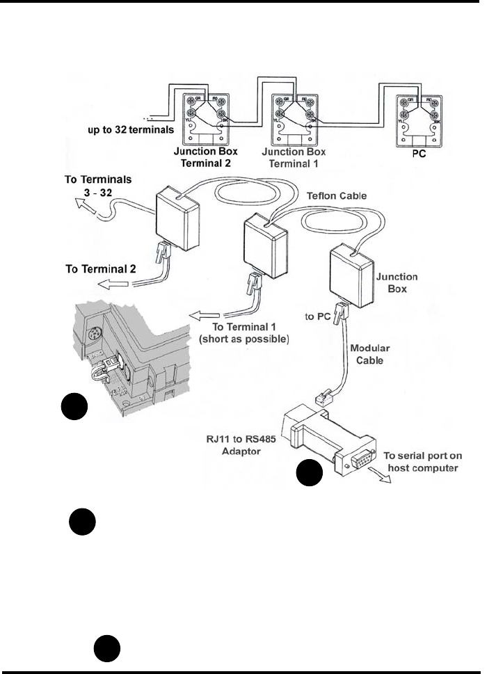
RS-485 Serial Cables
Junction Box “Daisy Chain” Wiring Diagram
Note: When wiring a network, always
follow the electric wiring codes in your
area. Typically, a Teflon coated wire
is required for wiring through a ceiling.
The junction box to junction box wire
shown is a teflon jacketed cable.
RS485 provides good protection
from interference over long runs
up to 4000 ft.
B
RS485 Wiring Diagram
The RS485 Serial port is
located on the left corner of
the terminal. RS485 is
imprinted on the terminal
casing.
RS485 communication allows
up to 32 terminals to be
connected to one serial port.
An RS232 port on the host PC
is used with an RS232/RS485
converter to complete the
connection. B
A
A
16
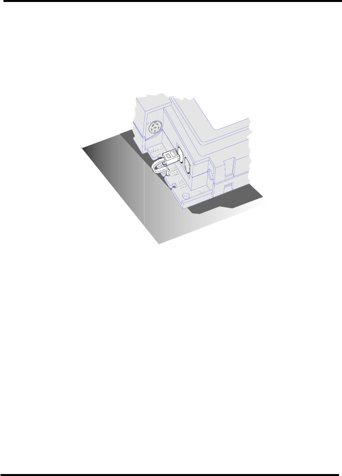
Modem Port
The port depicted may have either an RS-485, a Modem, or an Ethernet
Communication Device. Terminals, which are equipped with a Modem
port, will not have an Ethernet or RS-485 port. The Modem Port is a 6
position 4-pin female port, which will accept a male RJ-11 modular
connector.
The internal modem (modulator/demodulator) converts electronic data
into tones, which are then transmitted over phone lines.
Warning: do not plug the modem into a digital phone system
because it will damage the modem and void the
warranty.
17
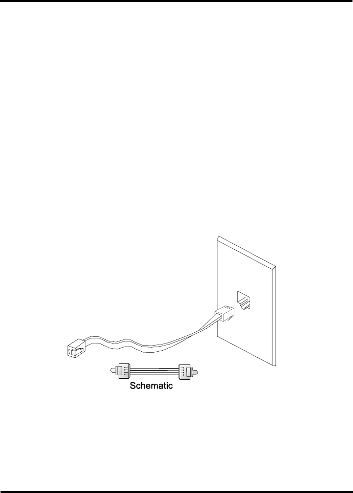
Modem Cables
Caution – To reduce the risk of fire, use only 26 AWG or larger
telecommunication line cord.
The cabling for modem operation is typically very simple. The modular
connection uses the two inner wires of the RJ-11 jack for “tip” and
“ring.”
Connect one end of the cable to the terminal and plug the other end into
your RJ-11 type modular telephone wall jack. The RJ-11 wall jack
should be of the analog telephone type and not a digital network jack.
Warning: Connecting to a digital network jack will
damage the modem.
If a modular wall jack is not available, obtain an adaptor from your
local telephone company.
.
18