Acroprint Time Recorder 1012 ENTRY CONTROL BADGE READER User Manual Micro computer Electronic Time Clock
Acroprint Time Recorder Company ENTRY CONTROL BADGE READER Micro computer Electronic Time Clock
Contents
- 1. USERS MANUAL 1
- 2. USERS MANUAL 2
- 3. USERS MANUAL 3
- 4. USERS MANUAL 4
USERS MANUAL 2
c) Proximity Readers
Two Proximity Readers are available on the DC7000. The first
Proximity Reader uses 125kHz, Read Only, ISO Proximity Card, 64 Bit
Encoding (Manchester). Serial Output Data String contains a 9 Bit
Header, 40 Bits of Data, 14 Parity Bits and 1 Stop Bit.
The second reader is a HID Reader that uses HID Badges:
125kHz, Read Only, H10301 (Std. 26 Bit), Facility Code 101.
Note: the reader is not restricted to 26 Bit badges
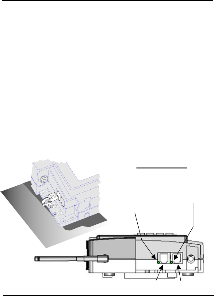
4. Ports and Connections
Ethernet Port
The Ethernet port is located on the lower left corner of the terminal. It is
a 10 position 8-pin female port, which will accept a male
10/100BASE-T (RJ-45) modular connector. The terminal has the
capability to communicate across an intranet, a WAN or the Internet.
Indicator Lights
Green Wireless
RF Activity
LED
Front Green LED:
Ethernet Link
Rear Green LED:
Ethernet Receive
Ethernet Port RS232 Port
12
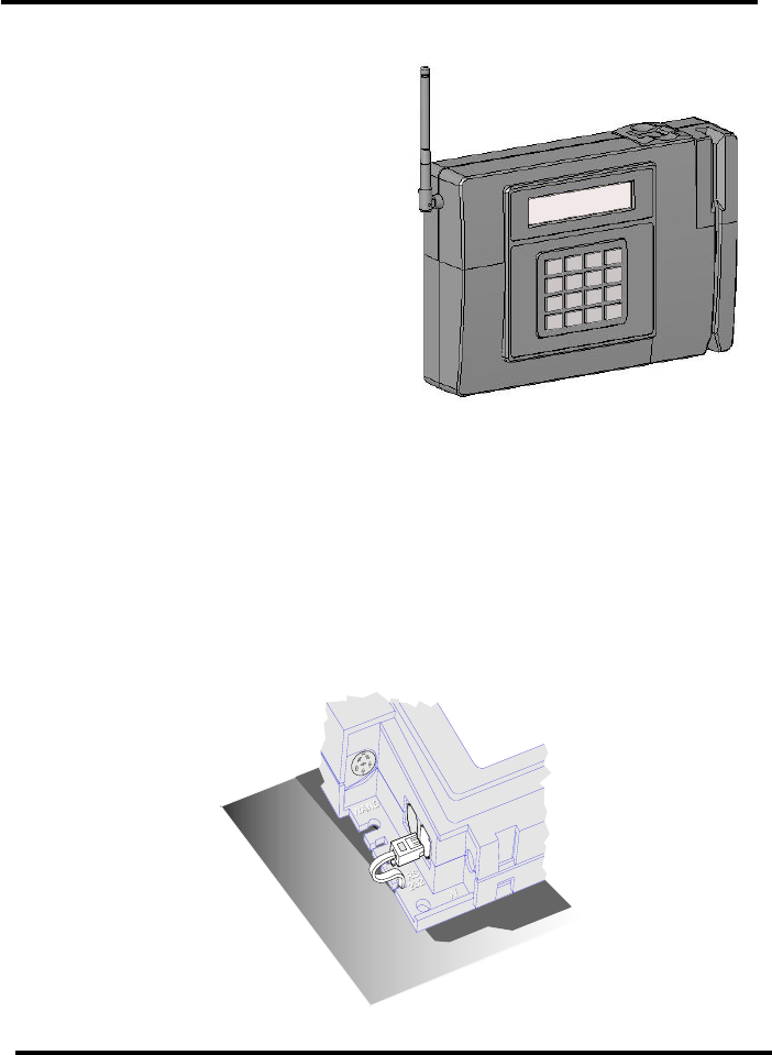
Wireless WiFi Connection
The Wireless Ethernet connection
is established via Wireless 802.11b.
RS-232 Serial port
The RS-232 serial port is located on the lower left corner of the
terminal. It is a six position 4-pin female port, which will accept a male
RJ-11 modular connector.
The DC7000 Terminal can use RS-232 serial communication to
connect directly to a host computer. A connection for an IBM® PC or
IBM-PC compatible computer is shown on the following page.
13