Acrowave Systems AAP-1100E 2.4GHz Wireless LAN User Manual users manual 1
Acrowave Systems Co., Ltd 2.4GHz Wireless LAN users manual 1
Contents
users manual 1


AcroLAN Access Point User’s Guide Version 2000.12.10
Copyright© Acrowave Systems 2000 DOC – xxx - yyy
Page 2 of 2
Contents
Chapter 1 Introduction To The Wireless LAN
1.1 What’s the Wireless LAN? …………………………………… 5
1.2 Wireless LAN Standard and Structure………………………… 6
Chapter 2 Setup AcroLAN Access Point ………………………. 13
2.1 Before You Begin Installation ……………………………… …. 13
2.2 Installing The Acrowave AcroLAN AWL-1100 Series Access Point
……………………………………. 15
Adjust the antennas ………………………………………… 15
Ethernet Cable Connection ………………………………… 16
Connect The Power Pack ………………………………….. 17
Connect Serial Cable ……………………………………….. 18
Open Terminal Program ……………………………………. 19
Configuration Change ………………………………………. 21
2.3 Verifying the Operation of the Acrowave Access Point ……….28
Chapter 3 Access Point Management……………………….……..30
3.1 Starting a Configuration Tool………………………………………31
Access Point Connection. ……………………………………32
Access Point Configuration Window..……………………….33
Terminal Window for Diagnosis ……………………………..37
Firmware Upgrade Window ………………..………………..38
Firmware Upgrade Via Internet ……………………………..39
Firmware Upgrade Via Local Disk…………………………..41
Access Point Detail Control………………………………….42
3.2 Setting Bridge Mode …………………………………………….. 43
Chapter 4 Troubleshooting …………………………………………..45

AcroLAN Access Point User’s Guide Version 2000.12.10
Copyright© Acrowave Systems 2000 DOC – xxx - yyy
Page 3 of 3
Appendix
Appendix A Cell Planning (Radio Range) …………………………….. 46
Appendix B Technical Specification …………………………………… 48
Appendix C Channel Allocation ……………………………..…………. 50

AcroLAN Access Point User’s Guide Version 2000.12.10
Copyright© Acrowave Systems 2000 DOC – xxx - yyy
Page 4 of 4
THE SPECIFICATIONS AND INFORMATION REGARDING THE PRODUCTS IN THIS MANUAL ARE SUBJECT TO CHANGE WITHOUT
NOTICE. ALL STATEMENTS, INFORMATION, AND RECOMMENDATIONS IN THIS MANUAL ARE BELIEVED TO BE ACCURATE BUT
ARE PRESENTED WITHOUT WARRANTY OF ANY KIND, EXPRESS OR IMPLIED. USERS MUST TAKE FULL RESPONSIBILITY FOR
THEIR APPLICATION OF ANY PRODUCTS.
THE SOFTWARE LICENSE AND LIMITED WARRANTY FOR THE ACCOMPANYING PRODUCT ARE SET FORTH IN THE
INFORMATION PACKET THAT SHIPPED WITH THE PRODUCT AND ARE INCORPORATED HEREIN BY THIS REFERENCE. IF YOU
ARE UNABLE TO LOCATE THE SOFTWARE LICENSE OR LIMITED WARRANTY, CONTACT YOUR ACROWAVE REPRESENTATIVE
FOR A COPY.
The following information is for FCC compliance of Class B devices: The equipment described in this manual generates and may radiate
radio-frequency energy. If it is not installed in accordance with Acrowave’s installation instructions, it may cause interference with radio and
television reception. This equipment has been tested and found to comply with the limits for a Class B digital device in accordance with the
specifications in part 15 of the FCC rules. These specifications are designed to provide reasonable protection against such interference in a
residential installation. However, there is no guarantee that interference will not occur in a particular installation.
Modifying the equipment without Acrowave’s written authorization may result in the equipment no longer complying with FCC requirements
for Class A or Class B digital devices. In that event, your right to use the equipment may be limited by FCC regulations, and you may be
required to correct any interference to radio or television communications at your own expense.
You can determine whether your equipment is causing interference by turning it off. If the interference stops, the Acrowave equipment or
one of its peripheral devices probably caused it. If the equipment causes interference to radio or television reception, try to correct the
interference by using one or more of the following measures:
• Turn the television or radio antenna until the interference stops.
• Move the equipment to one side or the other of the television or radio.
• Move the equipment farther away from the television or radio.
• Plug the equipment into an outlet that is on a different circuit from the television or radio. (That is, make certain the equipment and the
television or radios are on circuits controlled by different circuit breakers or fuses.)
Modifications to this product not authorized by Acrowave Systems Co., Ltd. could void the FCC approval and negate your authority to
operate the product.
NOTWITHSTANDING ANY OTHER WARRANTY HEREIN, ALL DOCUMENT FILES AND SOFTWARE OF THESE SUPPLIERS ARE
PROVIDED “AS IS” WITH ALL FAULTS. ACROWAVE AND THE ABOVE-NAMED SUPPLIERS DISCLAIM ALL WARRANTIES,

AcroLAN Access Point User’s Guide Version 2000.12.10
Copyright© Acrowave Systems 2000 DOC – xxx - yyy
Page 5 of 5
EXPRESSED OR IMPLIED, INCLUDING, WITHOUT LIMITATION, THOSE OF MERCHANTABILITY, FITNESS FOR A PARTICULAR
PURPOSE AND NONINFRINGEMENT OR ARISING FROM A COURSE OF DEALING, USAGE, OR TRADE PRACTICE.
IN NO EVENT SHALL ACROWAVE OR ITS SUPPLIERS BE LIABLE FOR ANY INDIRECT, SPECIAL, CONSEQUENTIAL, OR
INCIDENTAL DAMAGES, INCLUDING, WITHOUT LIMITATION, LOST PROFITS OR LOSS OR DAMAGE TO DATA ARISING OUT OF
THE USE OR INABILITY TO USE THIS MANUAL, EVEN IF ACROWAVE OR ITS SUPPLIERS HAVE BEEN ADVISED OF THE
POSSIBILITY OF SUCH DAMAGES.
AcroLAN, the Acrowave logo are registered trademarks of Acrowave Systems Co., Ltd. or its affiliates in the Korea, U.S. and certain other
countries. All other trademarks mentioned in this document are the property of their respective owners. The use of the word partner does
not imply a partnership relationship between Acrowave and any of its resellers.
The Acrowave AcroLAN Access Point User’s Guide
Copyright© 2000, Acrowave Systems Co., Ltd
All rights reserved.

AcroLAN Access Point User’s Guide Version 2000.12.10
Copyright© Acrowave Systems 2000 DOC – xxx - yyy
Page 6 of 6
Chapter 1 Introduction To The Wireless LAN
A wireless LAN (WLAN) is a flexible data communication system implemented as an
extension to, or as an alternative for, a wired LAN within a building or campus. Using
electromagnetic waves, WLANs transmit and receive data over the air, minimizing the
need for wired connections. Thus, WLANs combine data connectivity with user mobility,
and, through simplified configuration, enable movable LANs. WLANs have gained strong
popularity in a number of vertical markets, including the health-care, retail,
manufacturing, warehousing, and academic arenas. These industries have profited from
the productivity gains of using hand-held terminals and notebook computers to transmit
real-time information to centralized hosts for processing. Today WLANs are becoming
more widely recognized as a general-purpose connectivity alternative for a broad range
of business customers.
1.1 What’s Wireless LAN?
Wireless LANs use electromagnetic airwaves (radio and infrared) to communicate
information from one point to another without relying on any physical connection. Radio
waves are often referred to as radio carriers because they simply perform the function of
delivering energy to a remote receiver. The data being transmitted is superimposed on
the radio carrier so that it can be accurately extracted at the receiving end. This is
generally referred to as modulation of the carrier by the information being transmitted.
Once data is superimposed (modulated) onto the radio carrier, the radio signal occupies
more than a single frequency, since the frequency or bit rate of the modulating
information adds to the carrier.
Multiple radio carriers can exist in the same space at the same time without interfering
with each other if the radio waves are transmitted on different radio frequencies. To
extract data, a radio receiver tunes in (or selects) one radio frequency while rejecting all
other radio signals on different frequencies.
In a typical WLAN configuration, a transmitter/receiver (transceiver) device, called an
access point, connects to the wired network from a fixed location using standard
Ethernet cable. At a minimum, the access point receives, buffers, and transmits data
between the WLAN and the wired network infrastructure. A single access point can
support a small group of users and can function within a range of less than one hundred

AcroLAN Access Point User’s Guide Version 2000.12.10
Copyright© Acrowave Systems 2000 DOC – xxx - yyy
Page 7 of 7
to several hundred feet. The access point (or the antenna attached to the access point)
is usually mounted high but may be mounted essentially anywhere that is practical as
long as the desired radio coverage is obtained.
End users access the WLAN through wireless LAN adapters, which are implemented as
PC cards in notebook computers, or use PCI adapters in desktop computers. WLAN
adapters provide an interface between the client network operating system (NOS) and
the airwaves (via an antenna). The nature of the wireless connection is transparent to
the NOS.
1.2 Wireless LAN Standard and Structure
!
!!
! Wireless LAN Standard – IEEE802.11b
The widespread acceptance of WLANs depends on industry standardization to ensure
product compatibility and reliability among the various manufacturers. The Institute of
Electrical and Electronics Engineers (IEEE) ratified the original 802.11 specifications in
1997 as the standard for wireless LANs. That version of 802.11 provides for 1 Mbps and
2 Mbps data rates and a set of fundamental signaling methods and other services. The
most critical issue affecting WLAN demand has been limited throughput. The data rates
supported by the original 802.11 standard are too slow to support most general business
requirements and have slowed adoption of WLANs. Recognizing the critical need to
support higher data-transmission rates, the IEEE recently ratified the 802.11b standard
(also known as 802.11 High Rate) for transmissions of up to 11 Mbps.
With 802.11b, WLANs will be able to achieve wireless performance and throughput
comparable to wired Ethernet. Outside of the standards bodies, wireless industry leaders
have united to form the Wire-less Ethernet Compatibility Alliance (WECA).
WECA’s mission is to certify cross-vendor interoperability and compatibility of IEEE
802.11b wireless networking products and to promote that standard for the enterprise,
the small business, and the home. Members include WLAN semiconductor
manufacturers, WLAN providers, computer system vendors, and software makers.
!
!!
! Wireless LAN Network Equipment
802.11 defines two pieces of equipment, a wireless station, which is usually a PC
equipped with a wireless network interface card (NIC), and an access point (AP), which
acts as a bridge between the wireless and wired networks. An access point usually
AcroLAN Access Point User’s Guide Version 2000.12.10
Copyright© Acrowave Systems 2000 DOC – xxx - yyy
Page 8 of 8
consists of a radio, a wired network interface (e.g., 802.3), and bridging software
conforming to the 802.1d bridging standard. The access point acts as the base station
for the wireless network, aggregating access for multiple wireless stations onto the wired
network. Wireless end stations can be 802.11 PC Card, PCI.
!
!!
! Wireless LAN Network Configuration
The 802.11 standard define two modes: infrastructure mode and ad hoc mode (or
independent or peer-to-peer).
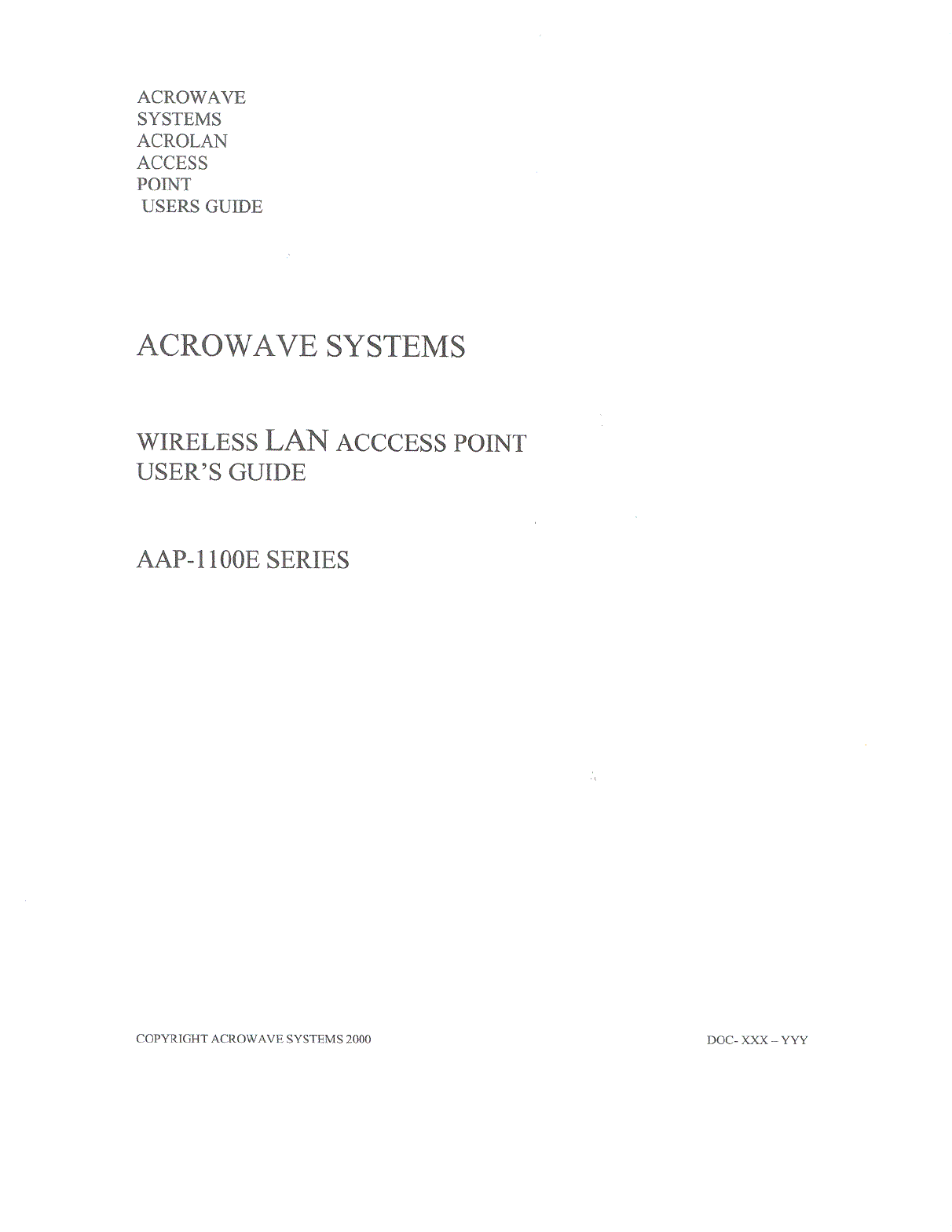
" Ad Hoc Mode
Ad hoc mode (also called peer-to-peer mode or an Independent Basic
Service Set, or IBSS) is simply a set of 802.11 wireless stations that
communicate directly with one another without using an access point or any
connection to a wired network. This mode is useful for quickly and easily
setting up a wireless network anywhere that a wireless infrastructure does not
exist or is not required for services, such as a hotel room, convention center,
or airport, or where access to the wired network is barred (such as for
consultants at a client site).
Figure 1. Ad Hoc Mode
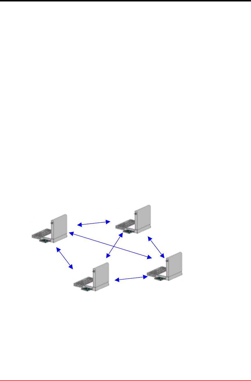
" Infrastructure Mode
In infrastructure mode, the wireless network consists of at least one access
Independent Basic
Service Set (IBSS)
AcroLAN Access Point User’s Guide Version 2000.12.10
Copyright© Acrowave Systems 2000 DOC – xxx - yyy
Page 9 of 9
point connected to the wired network infrastructure and a set of wireless end
stations. This configuration is called a Basic Service Set (BSS). An Extended
Service Set (ESS) is a set of two or more BSSs forming a single sub-network.
Since most corporate WLANs require access to the wired LAN for services
(file servers, printers, Inter-net links) they will operate in infrastructure mode.
Figure 2. Infrastructure Mode
!
!!
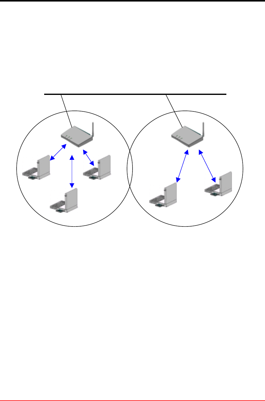
! Roaming
Wireless communication is limited by how far signals carry for given power output.
WLANs use cells, called microcells, similar to the cellular telephone system to extend
the range of wireless connectivity. At any point in time, a mobile PC equipped with a
WLAN adapter is associated with a single access point and its microcell, or area of
coverage. Individual microcells overlap to allow continuous communication within wired
network. They handle low power signals and “hand off” users as they roam through a
given geographic area.
The 802.11 MAC layer is responsible for how a client associates with an access point.
Distribution System (DS)
Service Set (SS) – Multiple
Access Point (AP)
Ethernet (802.3)
AcroLAN Access Point User’s Guide Version 2000.12.10
Copyright© Acrowave Systems 2000 DOC – xxx - yyy
Page 10 of 10
When an 802.11 client enters the range of one or more APs, it chooses an access point
to associate with (also called joining a Basic Service Set), based on signal strength and
observed packet error rates. Once accepted by the access point, the client tunes to the
radio channel to which the access point is set. Periodically it surveys all 802.11 channels
in order to assess whether a different access point would provide it with better
performance characteristics. If it determines that this is the case, it reassociates with the
new access point, tuning to the radio channel to which that access point is set.
Reassociation usually occurs because the wireless station has physically moved away
from the original access point, causing the signal to weaken. In other cases,
Reassociation occurs due to a change in radio characteristics in the building, or due
simply to high network traffic on the original access point. In the latter case this function
is known as “load balancing,” since its primary function is to distribute the total WLAN
load most efficiently across the available wireless infrastructure. This process of
dynamically associating and reassociating with APs allows network managers to set up
WLANs with very broad coverage by creating a series of overlapping 802.11b cells
throughout a building or across a campus. To be successful, the IT manager ideally will
employ “channel reuse,” taking care to set up each access point on an 802.11 DSSS
channel that does not overlap with a channel used by a neighboring access point.
Figure 3. Roaming
Backbone Network
Access Point (AP)
Inter-Cell Roaming