Acrowave Systems AAP-1100E 2.4GHz Wireless LAN User Manual users manual 5
Acrowave Systems Co., Ltd 2.4GHz Wireless LAN users manual 5
Contents
users manual 5
AcroLAN Access Point User’s Guide Version 2000.12.10
Copyright© Acrowave Systems 2000 DOC – xxx - yyy
Page 41 of 41
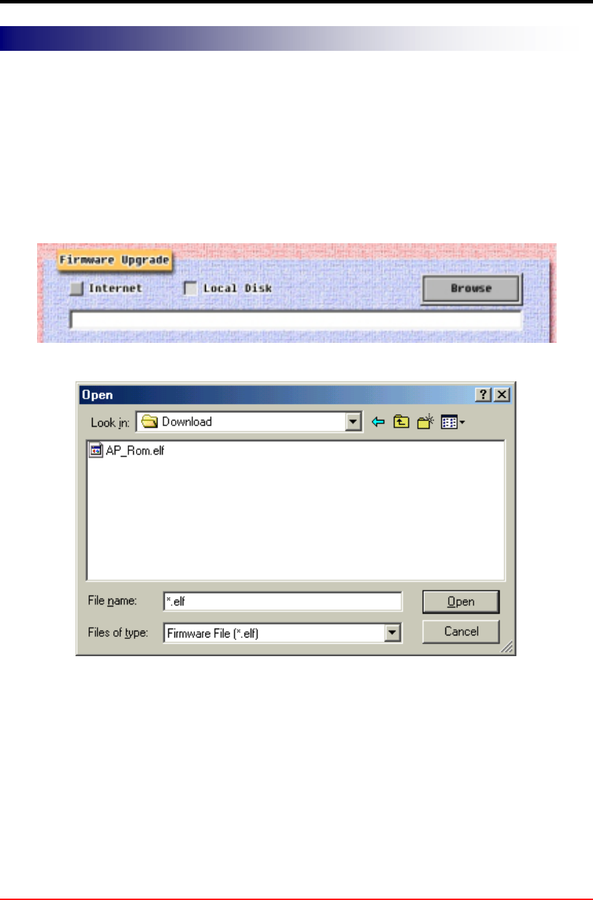
In order to upgrade Access Point firmware via local disk, click the Local Disk button. In
order to use this option, you should have latest firmware version in your local disk
already. After you click Browse button, select the firmware that you want to update. In
this time, you should take special attention in opening file so that not to open wrong file
or firmware version.
After confirm the file name, click the Start button. The other processes from this stage
are the same as those of the Internet.
Firmware Upgrade Via Local Disk
AcroLAN Access Point User’s Guide Version 2000.12.10
Copyright© Acrowave Systems 2000 DOC – xxx - yyy
Page 42 of 42
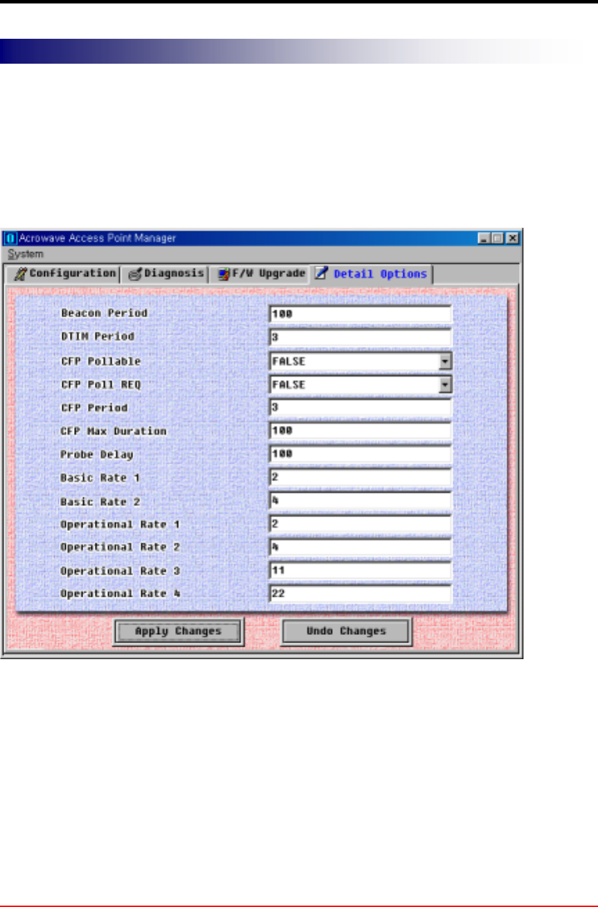
These windows is provided for wireless LAN expert only, so if you does not have deep
information about wireless LAN air interface specifications, do not change default
options. More detail information about how to change detail configuration will be
explained in Access Point Management section.
• Beacon Period: The amount of time between beacons.
• DTIM Period: This setting, always a multiple of the beacon period, determines how
often the beacon contains a delivery traffic indicator message (DTIM). The traffic
indicator message tells power-save clients that a packet is waiting for them.
Other items will be explained later vision of this document.
Access Point Detail Control

AcroLAN Access Point User’s Guide Version 2000.12.10
Copyright© Acrowave Systems 2000 DOC – xxx - yyy
Page 43 of 43
3.2 Setting Bridge Mode
You can connect two separate LANs over a wireless link by configuring two AcroLAN
Access Points to communicate with each other. This is called a LAN-to-LAN connection.
Two APs in different buildings using an outdoor antenna to connect the LANs in those
buildings can be deployed.
To configure two APs to communicate with each other in a LAN-to-LAN configuration,
perform the following tasks:
1) Get the wireless MAC address of the remote AP. You can see the wireless address
via the AP Manager or console device, as described in “Access Point Configuration
Window“ section. The wireless MAC address is NOT the same as the wired MAC
address printed on the front of the AP.
2) Set the Bridge Mode to LAN-to-LAN, as described in above “Access Point
Configuration Window section’s Type item.
3) Make sure that the APs use the same channel. To change the AP channel, see
“Access Point Configuration Window“ section.
The AP provides the following bridging services:
• Store-and-forward capability
The AP receives, checks, and transmits frames to other LANs, enabling the
configuration of extended LANs.
• Frame filtering based on address
Using the address database and the source and destination addresses from incoming
frames, the AP isolates the traffic that should not be allowed on other LANs. This
action reduces the total data traffic on an extended LAN by not forwarding the packets
that have local destination addresses or packets that are not allowed to forward. This
increases bandwidth efficiency.

AcroLAN Access Point User’s Guide Version 2000.12.10
Copyright© Acrowave Systems 2000 DOC – xxx - yyy
Page 44 of 44
• Data Link layer relay
The AP operates at the Data Link layer of the Open System Interconnection (OSI)
model. Operation at this layer makes the AP transparent to the protocols that use the
LAN connectivity service. This protocol transparency is a key factor in the extended
LAN service.

AcroLAN Access Point User’s Guide Version 2000.12.10
Copyright© Acrowave Systems 2000 DOC – xxx - yyy
Page 45 of 45
Chapter 4 Troubleshooting
T.B.D.

AcroLAN Access Point User’s Guide Version 2000.12.10
Copyright© Acrowave Systems 2000 DOC – xxx - yyy
Page 46 of 46
Appendix
Appendix A Cell Planning (Radio Range)
This section provides general guidelines on factors that influence network performance
Cell Site Survey
Because of differences in component configuration, placement and physical environment,
every network application is a unique installation. Before installing the system, users
should perform a site survey to determine the optimum utilization of networking
components and to maximize range, coverage and network performance.
Here are some operating and environmental conditions you should consider:
• Data Rates
Radio signal sensitivity and range are inversely proportional to data bit rates. The
maximum radio range is achieved at the lowest workable data rate. There will be a
decrease in receiver threshold sensitivity as the radio data rate increases.
• Antenna Type and Placement (PCI card only)
Proper antenna configuration is a critical factor in maximizing radio range. As a general
guide, range increases in proportion to antenna height. For a detailed explanation of
antenna types and configurations along with guidelines on selecting antennas for
specific environments, see the documentation that comes with your antenna.
• Physical Environments
Clear or open areas provide better radio range than closed or filled areas. Also, the less
cluttered the work environment, the greater the range.
• Obstructions
A physical obstruction such as metal shelving or a steel pillar can hinder the
performance of the client adapter. Avoid locating the computing device in a location
where there is a metal barrier between the sending and receiving antennas.

AcroLAN Access Point User’s Guide Version 2000.12.10
Copyright© Acrowave Systems 2000 DOC – xxx - yyy
Page 47 of 47
• Building Materials
Radio penetration is greatly influenced by the building material used in construction. For
example, drywall construction allows greater range than concrete blocks. Metal or steel
construction is a barrier to radio signals.
Enhancing Coverage
The system architecture options of the wireless station and AcroLAN Access Points
provide for a variety of coverage alternatives and flexibility. The system can be designed
to provide a wide coverage area with minimal overlap or coverage with heavy overlap.
The latter improves system performance and protection against downtime in the event of
a component failure. By arranging the AcroLAN Access Points so the overlap in
coverage area is minimized, a large area can be covered with minimal system cost. The
total bandwidth available to each mobile station will depend on the amount of data each
mobile station desires to transfer and the number of stations located in each cell.
Seamless roaming is supported as a mobile station moves in and out of range of each
AcroLAN Access Point, thereby maintaining a constant connection to the wired LAN.
Each device in the radio network must be configured with the same Service Set Identifier
(SSID) to provide the roaming capability. Multiple systems can operate in the same
vicinity. The architecture provides multiple channels, which can coexist in the same area
with virtually no interference to each other. In this mode, each system must be
configured with different Service Set Identifiers (SSID) and different channels, which
prevent clients from roaming to AcroLAN Access Points of a different wireless system.

AcroLAN Access Point User’s Guide Version 2000.12.10
Copyright© Acrowave Systems 2000 DOC – xxx - yyy
Page 48 of 48
Appendix B Technical Specifications
Functional Specification
Item Function
Configuration and setup . Local monitor
. Access Point Manager
Modes . Access Point
. Wireless LAN Bridge
Status Display Power, Air Link Status, Wire Link status
Software Upgradeable Via Access Point Manager or local monitor
Security WEP 64 bit standard, upgradeable to 128 bit
Approval WiFi, FCC (in processing)
Max. No of Clients per AP 255

AcroLAN Access Point User’s Guide Version 2000.12.10
Copyright© Acrowave Systems 2000 DOC – xxx - yyy
Page 49 of 49
Electrical/Radio Specifications
Item Specification Description
Compliance IEEE802.11b
Radio Type
Direct Sequence
Spread-Spectrum
(DSSS)
2.4 GHz ISM Band
Operating Frequency 2400-2483.5 MHz North American, ETSI, and Japan
channel coverage, factory configurable
Range Depending on data rate
and environment.
Accurate values must be calculated for
specific installation.
Data Rate 1, 2, 5,5 or 11Mbps Dynamic rate selection based on radio
medium quality.
FCC ID FCC approval
Number of Channels Max 14 Refer Appendix CHANNEL
Channeling 5 MHz increments Programmable for IEEE 802.11b
Type of Modulation
BPSK 1 Mbit/s
QPSK 2 Mbit/s
CCK 5.5 and 11 Mbits/s
Nominal 10 MHz BW
(-6 dB)
Receiver sensitivity
–87 dBm @ 1 Mbps
–85 dBm @ 2 Mbps
–84 dBm @ 5.5 Mbps
–81 dBm @ 11 Mbps
Wired LAN Interface 10Base-T RJ45 Connector
Serial Interface RS-232 @ 19.2Kbps DB-9 female
Power Consumption 4.5W @ 20°C
Power Supply 1.5A DC Input 100-240VAC, 60Hz 5V VDC
Dimension 157w x 128d x 27h MM
Weight 0.5Kg Without antenna
Operating Temperature 0°C ~ +55°C
Storage Temperature -30°C ~ +80°C
Operating Humidity 10% ~ 90% Non-condensing

AcroLAN Access Point User’s Guide Version 2000.12.10
Copyright© Acrowave Systems 2000 DOC – xxx - yyy
Page 50 of 50
Appendix C Channel Allocation
The channel identifiers and the channel center frequencies of each 22-MHz-wide channel are
shown in the table below, as appropriate for the various areas or regulatory agencies.
Regulatory Domains
Channel
Identifier
Center
Frequency North
America ETSI Spain France Korea /
Japan
1 2412MHz √
√√
√ √
√√
√ − − √
√√
√
2 2417MHz √
√√
√ √
√√
√ − − √
√√
√
3 2422MHz √
√√
√ √
√√
√ − − √
√√
√
4 2427MHz √
√√
√ √
√√
√ − − √
√√
√
5 2432MHz √
√√
√ √
√√
√ − − √
√√
√
6 2437MHz √
√√
√ √
√√
√ − − √
√√
√
7 2442MHz √
√√
√ √
√√
√ − − √
√√
√
8 2447MHz √
√√
√ √
√√
√ − − √
√√
√
9 2452MHz √
√√
√ √
√√
√ − − √
√√
√
10 2457MHz √
√√
√ √
√√
√ √
√√
√ √
√√
√ √
√√
√
11 2462MHz √
√√
√ √
√√
√ √
√√
√ √
√√
√ √
√√
√
12 2467MHz − √
√√
√ − √
√√
√ √
√√
√
13 2472MHz − √
√√
√ − √
√√
√ √
√√
√
14 2484MHz − − − − √
√√
√