Ademco 8DL5898 Dual Tech Motion Detector User Manual P800 01801A FCC
Honeywell International Inc. Dual Tech Motion Detector P800 01801A FCC
UserManual.wiki
>
Ademco
>
8DL5898 User Manual
User Manual
Navigation menu
Upload a User Manual
Namespaces
Wiki Guide
HTML
PDF
Info
Views
User Manual
Discussion / Help
Navigation
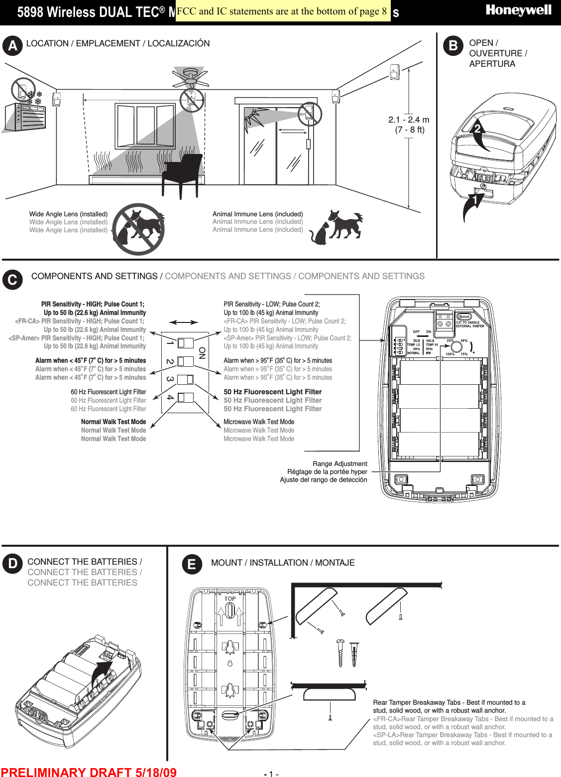
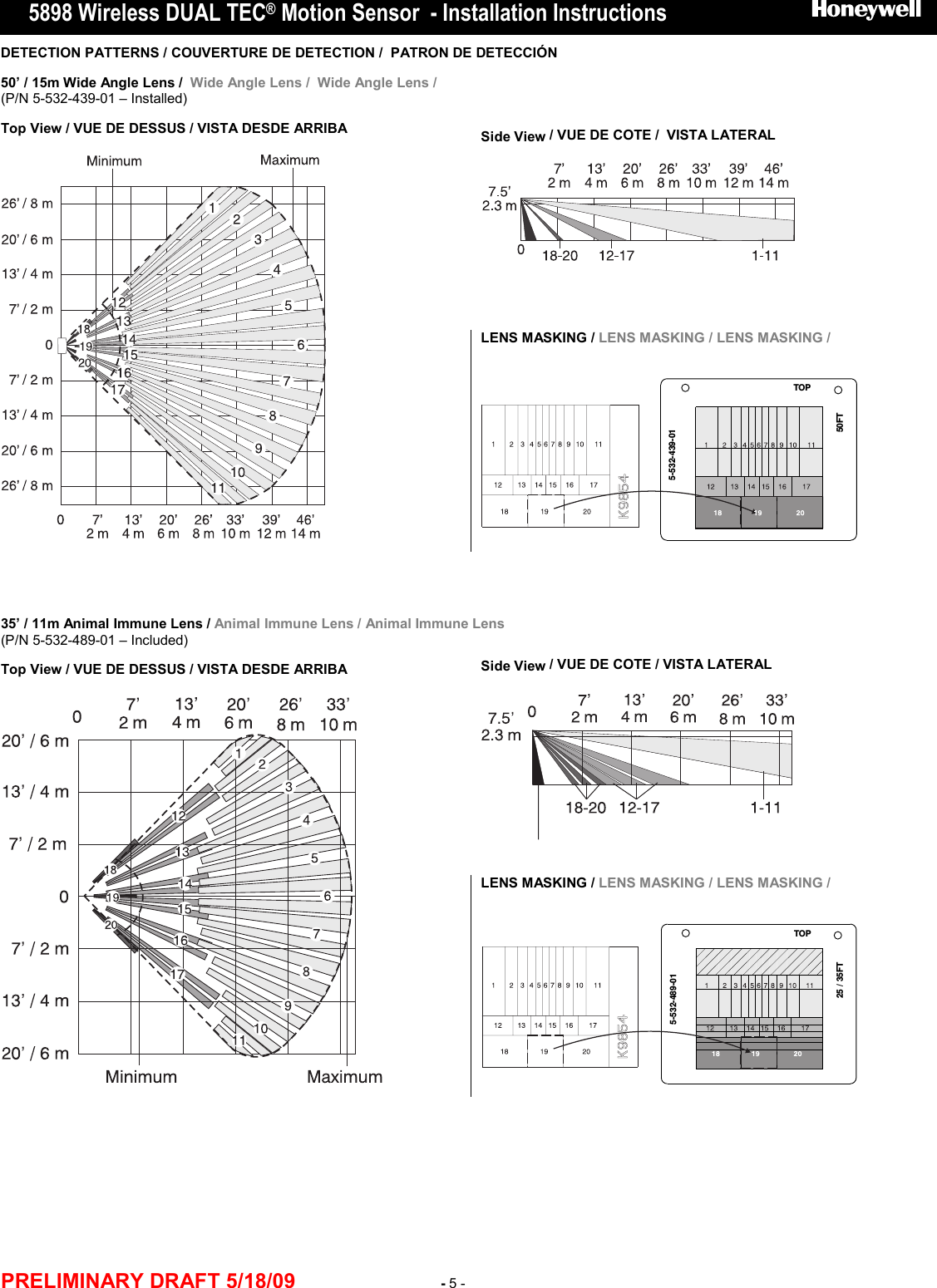
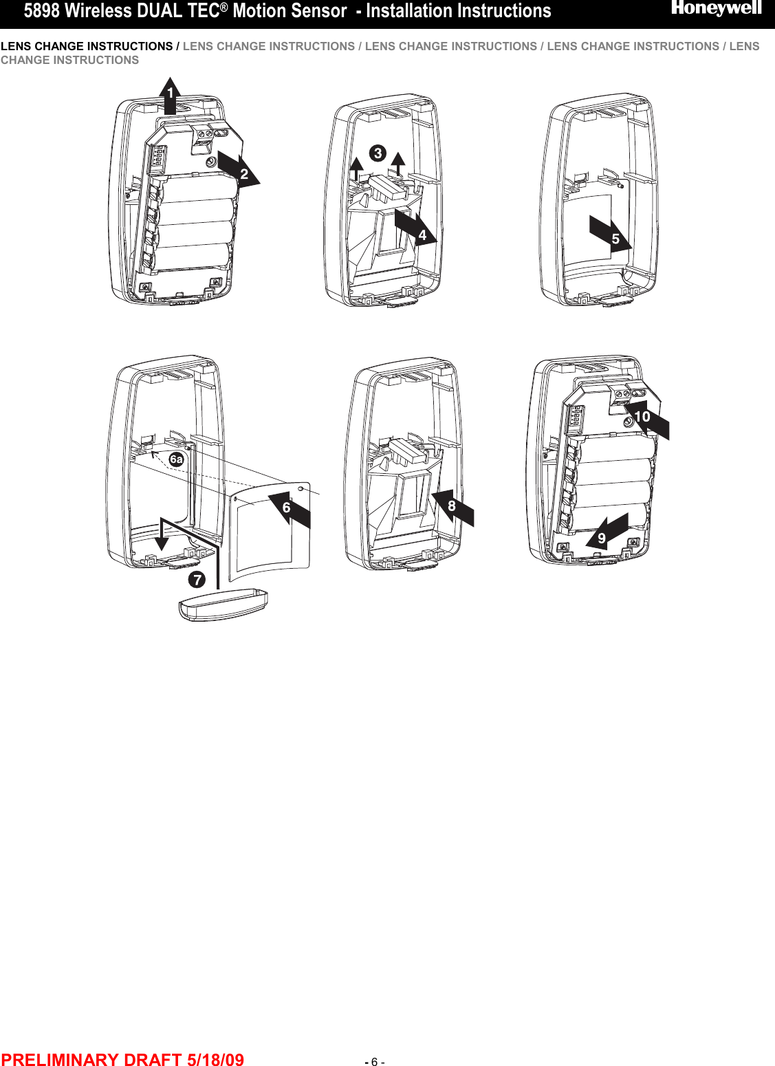
![5898 Wireless DUAL TEC® Motion Sensor - Installation Instructions English PRELIMINARY DRAFT 5/18/09 - 2 - 1 BEFORE MOUNTING Before mounting the transmitter permanently, conduct Go/No Go tests (see control panel manual) to verify adequate signal strength and reorient or relocate the sensor if necessary. For Animal Immunity: • Mount the center of the sensor at 7.5 ft (2.3 m) high. • Set the sensor to the Lowest or Low sensitivity (see step 6a). • Install Animal Immune lens (5-532-489-01 - see Lens Change Instructions on page X). • Install the look-down mask (see X). • Install the sensor where animals cannot come within 6 ft (1.8 m) of the sensor by climbing on furniture or other objects. • Aim the sensor away from stairways, furniture or other objects that can be climbed on by pets. 2 ENROLLING THE SENSOR After connecting the battery, the sensor LED will blink once per second for up to 60 seconds (power up), then Normal walk test mode begins. You must “enroll” the sensor’s ID in the system in this walk test mode. Eliminate activity in front of the sensor. When prompted for the sensor ID number, wave a hand in front of the sensor lens to trigger alarms and send sensor ID information to the panel. Refer to the control panel’s manual and the programming tool manual for information on registering wireless devices. Program the sensor as an “RF” type unit (supervised RF). Loop 1 Low Sensitivity (Pulse Count 2) / Animal Immunity [50 lb. (23 kg) / 100 lb. (45 kg)] Loop 2 High Sensitivity (Pulse Count 1) / No Animal Immunity Loop 3 Low Temperature Alarm Fault = < 45° F (7° C) for > 5 minutes Restore = > 48° F (9° C) for > 5 minutes High Temperature Alarm Fault = > 95° F (35° C) for > 5 minutes Restore = < 92° F (33° C) for > 5 minutes Loop 4 Tamper 3 WALK TEST MODES Normal Walk Test mode: The 10-minute Normal walk test mode is designed to optimize sensor enrollment. Only alarm signals for the selected sensitivity/loop are sent to the panel (default is low sensitivity / loop 1). Use the flashlight feature described below to toggle the sensitivity / loop setting. As you walk through the detection pattern, the sensor LED will either light or blink rapidly to indicate each alarm detection: - LED turns ON for 3 seconds = low sensitivity / loop 1. - LED blinks rapidly for 3 seconds = high sensitivity / loop 2. Flashlight feature: (only available for 24 hours after power-up.) • Stand within 4 feet (1.2 m) of the sensor with a flashlight. • Blink or wave the flashlight beam across the front of the sensor 3 to 5 times. (For best results, use a flashlight with a strong light beam and time the blinks/waves approximately once every ½ second.) • The sensor LED will flash for 3 seconds to indicate the sensitivity / loop setting has been changed. • Each time you use the flashlight feature the sensor sensitivity / loop toggles and the walk test timer restarts the walk test for 10 minutes. To restart a 10 minute Normal walk test mode after it expires, activate the tamper by opening and closing the sensor. If necessary, adjust the microwave range, pulse count or sensitivity setting. (For LED activation meaning, refer to the LED Indicator table.) 4 MICROWAVE WALK TEST – 10 MINUTES 1. Set the Microwave Walk Test DIP switch to ON, or toggle it ON and OFF. 2. Set Range Adjustment potentiometer to 25% and replace the cover. 3. Walk through the detection area and observe the LED. 4. If necessary, adjust the potentiometer until desired detection range is obtained. (For LED activation meaning, refer to the LED Indicator table.) Power UpTrouble or Anti-Mask Fast Blinking Red (LED Enabled or Disabled)Condition Indicator LEDSlow Blinking Red (will finish within 60 seconds)Indicator LEDsNormal Walk TestRed ON for 3 seconds if AlarmYellow ON for 2 seconds if Microwave event detectedGreen ON for 2 seconds if PIR event detectedMicrowave Walk TestRed ON if Microwave is set too highGreen ON if Microwave is set correctlyOFF if Microwave is set too low TROUBLESHOOTING The sensor indicates a trouble condition by blinking the LED once every 5 seconds. If a trouble condition (self test failure) occurs, the RF supervision is suppressed and the panel reports a trouble (“check zone”) after the condition exceeds the panel’s RF transmitter supervision time. (Self Tests: Microwave Supervision, End-to-End PIR self-test and Temperature Compensation.) Solution: Remove and replace the battery. If the trouble does not clear, replace the sensor. Replace the battery within 7 days after a “low battery” message appears in the system’s display. SPECIFICATIONS Range: 50’ x 60’ (15 m x 18 m) [installed] 35’ x 40’ (11 m x 12 m) [included] Batteries: Four 1.5V AA Lithium Batteries (Use only Energizer L91) Battery Caution: Risk of fire, explosion and burns. Do not recharge, disassemble, heat above 100° C (212° F), or incinerate. Dispose of used batteries promptly. Keep away from children. Microwave Frequency: 24.125 GHz (K-band) RF Frequency: 345 MHz PIR White Light Immunity: 6,500 Lux typical Fluorescent Light Filter: 50 Hz or 60 Hz, switch selectable Operating Temperature: -20° to 55° C (-4° to 131° F), 5% - 95% relative humidity (non-condensing) Self-Tests: Microwave supervision; End-to-End PIR self-test; Temperature Compensation Temperature Compensation: Advanced Dual Slope PIR Fields of View: Wide Angle Lens (P/N 5-532-439-01) 44 long range zones 12 intermediate zones 6 lower zones 4 look-down zones Animal Immune Lens (P/N 5-532-489-01) 44 long range zones 36 intermediate zones 18 lower zones 4 look-down zones Dimensions: 4.93” x 2.93” x 1.68” (12.5cm x 7.5cm x 4.3cm) Weight: 149.0 g (5.26 oz); Packaged: 205.0 g (7.23 oz) Accessories: Optional Lens Kits - Long Range Curtain Lens Kit 15 m x 3 m / 50’ x 10’ (P/N DT7000-LRLK) High Security Lens Kit 11 m x 12 m / 35’ x 40’ (P/N DT7000-HSLK) Pet Alley Lens Kit 11 m x 12 m / 35’ x 40’ (P/N DT7000-PALK) Mounting Brackets – SMB-10 Swivel Mount Bracket (P/N 0-000-110-01) SMB-10C Swivel Mount Ceiling Bracket (P/N 0-000-111-01) Approval Listings: FCC Part 15, Class B verified IC RSS-210, Class B verified C-Tick, cULus Listed COMPLIANCE NOTES • Sensor must be tested once per year. • Sensor must have a clear line-of-sight to protected area.](https://usermanual.wiki/Ademco/8DL5898/User-Guide-1118011-Page-2.png)
![5898 Wireless DUAL TEC® Motion Sensor - Installation Instructions FR-Canadian PRELIMINARY DRAFT 5/18/09 - 3 - 1 SELECT MOUNTING LOCATION (See A) Additional guidelines for animal immunity: • Mount the center of the sensor at 2.3 m (7.5 feet) high. • Set the sensor to the Lowest or Low sensitivity (see step 6a). • Install Animal Immune lens (5-532-489-01 - see Lens Change Instructions on page 3). • Install the look-down mask (see Step 6a). • Install the sensor where animals cannot come within 1.8 m (6 ft) of the sensor by climbing on furniture or other objects. • Aim the sensor away from stairways, furniture or other objects that can be climbed on by pets. • TEST the installation site to determine the exact level of attainable animal immunity. 2 REMOVE THE FRONT HOUSING (SEE B) 3 SELECT THE RANGE, SENSITIVITY AND PROTOCOL (SEE C) 4 CONNECT THE BATTERIES (SEE D) 5 REGISTER THE SENSOR TO THE PANEL Refer to the control panel’s manual and the programming tool manual for information on registering wireless devices. Once you enter the sensor serial number into the panel programming, select the desired loop for that zone. Serial # / LOOP Serial #1 / Loop 1 High Sensitivity No Animal Immunity Pulse Count 1 Serial #1 / Loop2 Low Sensitivity / Animal Immunity [23 kg (50 lb.) / 45 kg (100 lb.)] Pulse Count 2 Serial #2 / Loop 1 Low Temperature Trip When temperature drops below 7° C ± 2° C (45° F ± 4° F) for 5 minutes Low Temp Restoral When temperature rises + 2° C (+ 3° F) above low temperature trip point Serial #2 / Loop 2 High Temperature Trip When temperature rises above 35° C ± 2° C (95° F ± 4° F) for 5 minutes Low Temp Restoral When temperature crops - 2° C (- 3° F) below high temperature trip point 6 MOUNT THE SENSOR (SEE E) 7 NORMAL WALK TEST– 10 MINUTES Normal walk test mode activates every time the front cover is closed and remains active for 10 minutes. For an additional 10 minutes of walk test time, remove and replace the front cover. In walk test mode, the LED is always enabled. Walk through the detection area and observe the LED. If necessary, adjust the microwave range, pulse count or sensitivity setting. (For LED activation meaning, refer to the LED Indicator table.) 8 MICROWAVE WALK TEST – 10 MINUTES 1. Set the Microwave Walk Test DIP switch to ON, or toggle it ON and OFF. 2. Set Range Adjustment potentiometer to 25% and replace the cover. 3. Walk through the detection area and observe the LED. 4. If necessary, adjust the potentiometer until desired detection range is obtained. (For LED activation meaning, refer to the LED Indicator table.) Power UpTrouble or Anti-Mask Fast Blinking Red (LED Enabled or Disabled)Condition Indicator LEDSlow Blinking Red (will finish within 60 seconds)Indicator LEDsNormal Walk TestRed ON for 3 seconds if AlarmYellow ON for 2 seconds if Microwave event detectedGreen ON for 2 seconds if PIR event detectedMicrowave Walk TestRed ON if Microwave is set too highGreen ON if Microwave is set correctlyOFF if Microwave is set too low TROUBLESHOOTING RED LED flashing rapidly during normal operation indicates a trouble condition. A microwave, PIR, or temperature compensation fault is present, or a communication error has occured. Supervision errors and low battery conditions are indicated at the panel. Solution: Momentarily power down the sensor by removing and replacing all the batteries. If the trouble does not clear, replace the sensor. SPECIFICATIONS Range: 50’ x 60’ (15 m x 18 m) [installed] 35’ x 40’ (11 m x 12 m) [included] Batteries: Four 1.5V AA Lithium Batteries (Use only Energizer L91) Battery Caution: Risk of fire, explosion and burns. Do not recharge, disassemble, heat above 100° C (212° F), or incinerate. Dispose of used batteries promptly. Keep away from children. Microwave Frequency: 24.125 GHz (K-band) RF Frequency: 345 MHz PIR White Light Immunity: 6,500 Lux typical Fluorescent Light Filter: 50 Hz or 60 Hz, switch selectable Operating Temperature: -20° to 55° C (-4° to 131° F), 5% - 95% relative humidity (non-condensing) Self-Tests: Microwave supervision; End-to-End PIR self-test; Temperature Compensation Temperature Compensation: Advanced Dual Slope PIR Fields of View: Wide Angle Lens (P/N 5-532-439-01) 44 long range zones 12 intermediate zones 6 lower zones 4 look-down zones Animal Immune Lens (P/N 5-532-489-01) 44 long range zones 36 intermediate zones 18 lower zones 4 look-down zones Dimensions: 4.93” x 2.93” x 1.68” (12.5cm x 7.5cm x 4.3cm) Weight: 149.0 g (5.26 oz); Packaged: 205.0 g (7.23 oz) Accessories: Optional Lens Kits - Long Range Curtain Lens Kit 15 m x 3 m / 50’ x 10’ (P/N DT7000-LRLK) High Security Lens Kit 11 m x 12 m / 35’ x 40’ (P/N DT7000-HSLK) Pet Alley Lens Kit 11 m x 12 m / 35’ x 40’ (P/N DT7000-PALK) Mounting Brackets – SMB-10 Swivel Mount Bracket (P/N 0-000-110-01) SMB-10C Swivel Mount Ceiling Bracket (P/N 0-000-111-01) Approval Listings: FCC IC CE, C-Tick, cULus Listed COMPLIANCE NOTES • Sensor must be tested once per year. • Sensor must have a clear line-of-sight to protected area.](https://usermanual.wiki/Ademco/8DL5898/User-Guide-1118011-Page-3.png)
![5898 Wireless DUAL TEC® Motion Sensor - Installation Instructions SP- Americas PRELIMINARY DRAFT 5/18/09 - 4 - 1 SELECT MOUNTING LOCATION (See A) Additional guidelines for animal immunity: • Mount the center of the sensor at 2.3 m (7.5 feet) high. • Set the sensor to the Lowest or Low sensitivity (see step 6a). • Install Animal Immune lens (5-532-489-01 - see Lens Change Instructions on page 3). • Install the look-down mask (see Step 6a). • Install the sensor where animals cannot come within 1.8 m (6 ft) of the sensor by climbing on furniture or other objects. • Aim the sensor away from stairways, furniture or other objects that can be climbed on by pets. • TEST the installation site to determine the exact level of attainable animal immunity. 2 REMOVE THE FRONT HOUSING (SEE B) 3 SELECT THE RANGE, SENSITIVITY AND PROTOCOL (SEE C) 4 CONNECT THE BATTERIES (SEE D) 5 REGISTER THE SENSOR TO THE PANEL Refer to the control panel’s manual and the programming tool manual for information on registering wireless devices. Once you enter the sensor serial number into the panel programming, select the desired loop for that zone. Serial # / LOOP Serial #1 / Loop 1 High Sensitivity No Animal Immunity Pulse Count 1 Serial #1 / Loop2 Low Sensitivity / Animal Immunity [23 kg (50 lb.) / 45 kg (100 lb.)] Pulse Count 2 Serial #2 / Loop 1 Low Temperature Trip When temperature drops below 7° C ± 2° C (45° F ± 4° F) for 5 minutes Low Temp Restoral When temperature rises + 2° C (+ 3° F) above low temperature trip point Serial #2 / Loop 2 High Temperature Trip When temperature rises above 35° C ± 2° C (95° F ± 4° F) for 5 minutes Low Temp Restoral When temperature crops - 2° C (- 3° F) below high temperature trip point 6 MOUNT THE SENSOR (SEE E) 7 NORMAL WALK TEST– 10 MINUTES Normal walk test mode activates every time the front cover is closed and remains active for 10 minutes. For an additional 10 minutes of walk test time, remove and replace the front cover. In walk test mode, the LED is always enabled. Walk through the detection area and observe the LED. If necessary, adjust the microwave range, pulse count or sensitivity setting. (For LED activation meaning, refer to the LED Indicator table.) 8 MICROWAVE WALK TEST – 10 MINUTES 1. Set the Microwave Walk Test DIP switch to ON, or toggle it ON and OFF. 2. Set Range Adjustment potentiometer to 25% and replace the cover. 3. Walk through the detection area and observe the LED. 4. If necessary, adjust the potentiometer until desired detection range is obtained. (For LED activation meaning, refer to the LED Indicator table.) Power UpTrouble or Anti-Mask Fast Blinking Red (LED Enabled or Disabled)Condition Indicator LEDSlow Blinking Red (will finish within 60 seconds)Indicator LEDsNormal Walk TestRed ON for 3 seconds if AlarmYellow ON for 2 seconds if Microwave event detectedGreen ON for 2 seconds if PIR event detectedMicrowave Walk TestRed ON if Microwave is set too highGreen ON if Microwave is set correctlyOFF if Microwave is set too low TROUBLESHOOTING RED LED flashing rapidly during normal operation indicates a trouble condition. A microwave, PIR, or temperature compensation fault is present, or a communication error has occured. Supervision errors and low battery conditions are indicated at the panel. Solution: Momentarily power down the sensor by removing and replacing all the batteries. If the trouble does not clear, replace the sensor. SPECIFICATIONS Range: 50’ x 60’ (15 m x 18 m) [installed] 35’ x 40’ (11 m x 12 m) [included] Batteries: Four 1.5V AA Lithium Batteries (Use only Energizer L91) Battery Caution: Risk of fire, explosion and burns. Do not recharge, disassemble, heat above 100° C (212° F), or incinerate. Dispose of used batteries promptly. Keep away from children. Microwave Frequency: 24.125 GHz (K-band) RF Frequency: 345 MHz PIR White Light Immunity: 6,500 Lux typical Fluorescent Light Filter: 50 Hz or 60 Hz, switch selectable Operating Temperature: -20° to 55° C (-4° to 131° F), 5% - 95% relative humidity (non-condensing) Self-Tests: Microwave supervision; End-to-End PIR self-test; Temperature Compensation Temperature Compensation: Advanced Dual Slope PIR Fields of View: Wide Angle Lens (P/N 5-532-439-01) 44 long range zones 12 intermediate zones 6 lower zones 4 look-down zones Animal Immune Lens (P/N 5-532-489-01) 44 long range zones 36 intermediate zones 18 lower zones 4 look-down zones Dimensions: 4.93” x 2.93” x 1.68” (12.5cm x 7.5cm x 4.3cm) Weight: 149.0 g (5.26 oz); Packaged: 205.0 g (7.23 oz) Accessories: Optional Lens Kits - Long Range Curtain Lens Kit 15 m x 3 m / 50’ x 10’ (P/N DT7000-LRLK) High Security Lens Kit 11 m x 12 m / 35’ x 40’ (P/N DT7000-HSLK) Pet Alley Lens Kit 11 m x 12 m / 35’ x 40’ (P/N DT7000-PALK) Mounting Brackets – SMB-10 Swivel Mount Bracket (P/N 0-000-110-01) SMB-10C Swivel Mount Ceiling Bracket (P/N 0-000-111-01) Approval Listings: FCC IC CE, C-Tick, cULus Listed COMPLIANCE NOTES • Sensor must be tested once per year. • Sensor must have a clear line-of-sight to protected area.](https://usermanual.wiki/Ademco/8DL5898/User-Guide-1118011-Page-4.png)