Ademco 8DL5898 Dual Tech Motion Detector User Manual P800 01801A FCC
Honeywell International Inc. Dual Tech Motion Detector P800 01801A FCC
Ademco >
User Manual
5898 Wireless DUAL TEC
®
Motion Sensor - Installation Instructions
PRELIMINARY DRAFT 5/18/09
- 1 -
OPEN /
OUVERTURE /
APERTURA
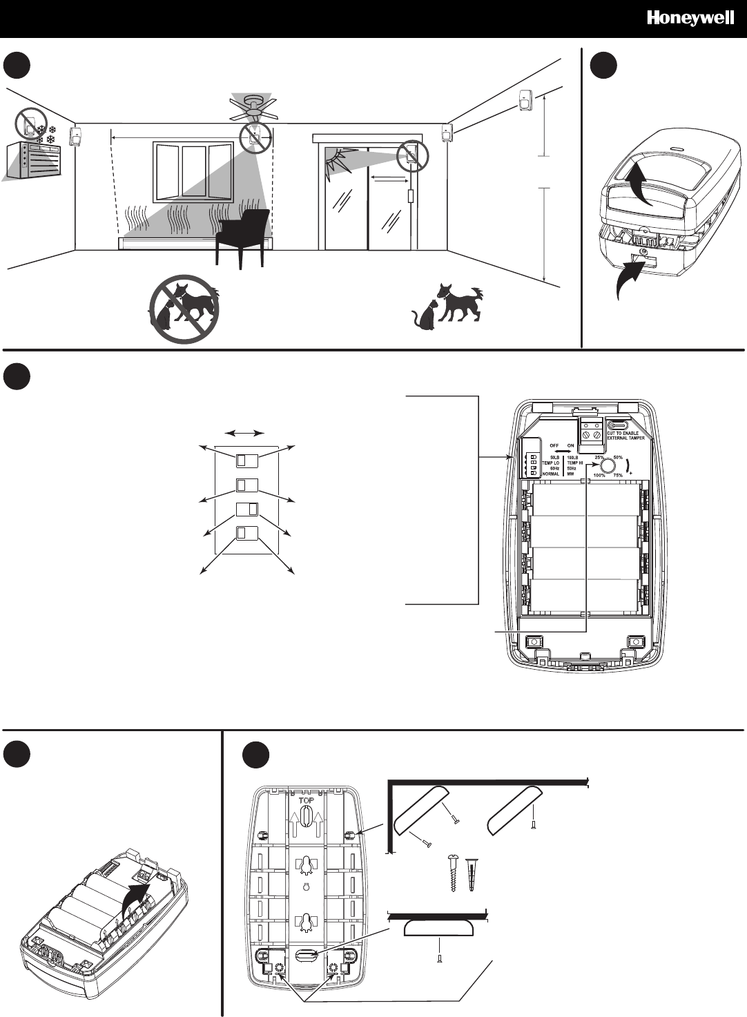
LOCATION / EMPLACEMENT / LOCALIZACIÓN
2.1 - 2.4 m
(7 - 8 ft)
AB
Wide Angle Lens (installed)
Wide Angle Lens (installed)
Wide Angle Lens (installed)
Animal Immune Lens (included)
Animal Immune Lens (included)
Animal Immune Lens (included)
2
1
COMPONENTS AND SETTINGS / COMPONENTS AND SETTINGS / COMPONENTS AND SETTINGS
C
Range Adjustment
Réglage de la portée hyper
Ajuste del rango de detección
E
CONNECT THE BATTERIES /
CONNECT THE BATTERIES /
CONNECT THE BATTERIES
D
MOUNT / INSTALLATION / MONTAJE
Rear Tamper Breakaway Tabs - Best if mounted to a
stud, solid wood, or with a robust wall anchor.
<FR-CA>Rear Tamper Breakaway Tabs - Best if mounted to a
stud, solid wood, or with a robust wall anchor.
<SP-LA>Rear Tamper Breakaway Tabs - Best if mounted to a
stud, solid wood, or with a robust wall anchor.
ON
2 3 41
ON
23 41
PIR Sensitivity - LOW; Pulse Count 2;
Up to 100 lb (45 kg) Animal Immunity
<FR-CA> PIR Sensitivity - LOW; Pulse Count 2;
Up to 100 lb (45 kg) Animal Immunity
<SP-Amer> PIR Sensitivity - LOW; Pulse Count 2;
Up to 100 lb (45 kg) Animal Immunity
PIR Sensitivity - HIGH; Pulse Count 1;
Up to 50 lb (22.6 kg) Animal Immunity
<FR-CA> PIR Sensitivity - HIGH; Pulse Count 1;
Up to 50 lb (22.6 kg) Animal Immunity
<SP-Amer> PIR Sensitivity - HIGH; Pulse Count 1;
Up to 50 lb (22.6 kg) Animal Immunity
60 Hz Fluorescent Light Filter
60 Hz Fluorescent Light Filter
60 Hz Fluorescent Light Filter
50 Hz Fluorescent Light Filter
50 Hz Fluorescent Light Filter
50 Hz Fluorescent Light Filter
Alarm when < 45o F (7o C) for > 5 minutes
Alarm when < 45o F (7o C) for > 5 minutes
Alarm when < 45o F (7o C) for > 5 minutes
Alarm when > 95o F (35o C) for > 5 minutes
Alarm when > 95o F (35o C) for > 5 minutes
Alarm when > 95o F (35o C) for > 5 minutes
Microwave Walk Test Mode
Microwave Walk Test Mode
Microwave Walk Test Mode
Normal Walk Test Mode
Normal Walk Test Mode
Normal Walk Test Mode
FCC and IC statements are at the bottom of page 8
5898 Wireless DUAL TEC
®
Motion Sensor - Installation Instructions English
PRELIMINARY DRAFT 5/18/09
- 2 -
1
BEFORE MOUNTING
Before mounting the transmitter permanently, conduct Go/No Go tests
(see control panel manual) to verify adequate signal strength and
reorient or relocate the sensor if necessary.
For Animal Immunity:
• Mount the center of the sensor at 7.5 ft (2.3 m) high.
• Set the sensor to the Lowest or Low sensitivity (see step 6a).
• Install Animal Immune lens (5-532-489-01 - see Lens Change
Instructions on page X).
• Install the look-down mask (see X).
• Install the sensor where animals cannot come within 6 ft (1.8 m) of
the sensor by climbing on furniture or other objects.
• Aim the sensor away from stairways, furniture or other objects that
can be climbed on by pets.
2 ENROLLING THE SENSOR
After connecting the battery, the sensor LED will blink once per second
for up to 60 seconds (power up), then Normal walk test mode begins.
You must “enroll” the sensor’s ID in the system in this walk test mode.
Eliminate activity in front of the sensor. When prompted for the sensor
ID number, wave a hand in front of the sensor lens to trigger alarms
and send sensor ID information to the panel.
Refer to the control panel’s manual and the programming tool manual
for information on registering wireless devices. Program the sensor
as an “RF” type unit (supervised RF).
Loop 1 Low Sensitivity (Pulse Count 2) /
Animal Immunity [50 lb. (23 kg) / 100 lb. (45 kg)]
Loop 2 High Sensitivity (Pulse Count 1) / No Animal Immunity
Loop 3
Low Temperature Alarm
Fault = < 45° F
(7° C) for > 5 minutes
Restore = > 48° F
(9° C) for > 5 minutes
High Temperature Alarm
Fault = > 95° F
(35° C) for > 5 minutes
Restore = < 92° F
(33° C) for > 5 minutes
Loop 4 Tamper
3 WALK TEST MODES
Normal Walk Test mode: The 10-minute Normal walk test mode is
designed to optimize sensor enrollment. Only alarm signals for the
selected sensitivity/loop are sent to the panel (default is low sensitivity /
loop 1). Use the flashlight feature described below to toggle the
sensitivity / loop setting.
As you walk through the detection pattern, the sensor LED will either
light or blink rapidly to indicate each alarm detection:
- LED turns ON for 3 seconds = low sensitivity / loop 1.
- LED blinks rapidly for 3 seconds = high sensitivity / loop 2.
Flashlight feature: (only available for 24 hours after power-up.)
• Stand within 4 feet (1.2 m) of the sensor with a flashlight.
• Blink or wave the flashlight beam across the front of the sensor 3 to
5 times. (For best results, use a flashlight with a strong light beam
and time the blinks/waves approximately once every ½ second.)
• The sensor LED will flash for 3 seconds to indicate the sensitivity /
loop setting has been changed.
• Each time you use the flashlight feature the sensor sensitivity / loop
toggles and the walk test timer restarts the walk test for 10 minutes.
To restart a 10 minute Normal walk test mode after it expires, activate
the tamper by opening and closing the sensor.
If necessary, adjust the microwave range, pulse count or sensitivity
setting. (For LED activation meaning, refer to the LED Indicator table.)
4 MICROWAVE WALK TEST – 10 MINUTES
1. Set the Microwave Walk Test DIP switch to ON, or toggle it ON and
OFF.
2. Set Range Adjustment potentiometer to 25% and replace the cover.
3. Walk through the detection area and observe the LED.
4. If necessary, adjust the potentiometer until desired detection range
is obtained. (For LED activation meaning, refer to the LED Indicator
table.)
Power Up
Trouble or Anti-Mask Fast Blinking Red (LED Enabled
or Disabled)
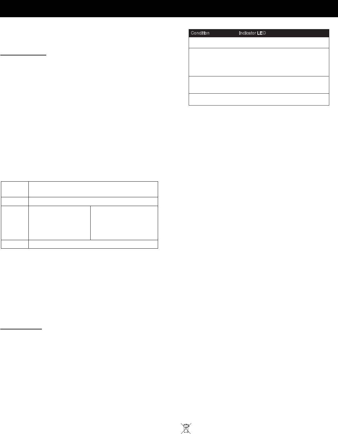
Condition Indicator LED
Slow Blinking Red (will finish within
60 seconds)
Indicator LEDs
Normal Walk Test
Red ON for 3 seconds if Alarm
Yellow ON for 2 seconds if Microwave
event detected
Green ON for 2 seconds if PIR event
detected
Microwave Walk Test
Red ON if Microwave is set too high
Green ON if Microwave is set correctly
OFF if Microwave is set too low
TROUBLESHOOTING
The sensor indicates a trouble condition by blinking the LED once
every 5 seconds. If a trouble condition (self test failure) occurs, the RF
supervision is suppressed and the panel reports a trouble (“check
zone”) after the condition exceeds the panel’s RF transmitter
supervision time. (Self Tests: Microwave Supervision, End-to-End PIR
self-test and Temperature Compensation.)
Solution: Remove and replace the battery. If the trouble does not
clear, replace the sensor.
Replace the battery within 7 days after a “low battery” message
appears in the system’s display.
SPECIFICATIONS
Range: 50’ x 60’ (15 m x 18 m) [installed]
35’ x 40’ (11 m x 12 m) [included]
Batteries: Four 1.5V AA Lithium Batteries (Use only Energizer L91)
Battery Caution: Risk of fire, explosion and burns. Do not
recharge, disassemble, heat above 100° C (212° F), or incinerate.
Dispose of used batteries promptly. Keep away from children.
Microwave Frequency: 24.125 GHz (K-band)
RF Frequency: 345 MHz
PIR White Light Immunity: 6,500 Lux typical
Fluorescent Light Filter: 50 Hz or 60 Hz, switch selectable
Operating Temperature: -20° to 55° C (-4° to 131° F),
5% - 95% relative humidity (non-condensing)
Self-Tests:
Microwave supervision; End-to-End PIR self-test; Temperature
Compensation
Temperature Compensation: Advanced Dual Slope
PIR Fields of View:
Wide Angle Lens (P/N 5-532-439-01)
44 long range zones 12 intermediate zones
6 lower zones 4 look-down zones
Animal Immune Lens (P/N 5-532-489-01)
44 long range zones 36 intermediate zones
18 lower zones 4 look-down zones
Dimensions: 4.93” x 2.93” x 1.68” (12.5cm x 7.5cm x 4.3cm)
Weight: 149.0 g (5.26 oz); Packaged: 205.0 g (7.23 oz)
Accessories:
Optional Lens Kits -
Long Range Curtain Lens Kit 15 m x 3 m / 50’ x 10’ (P/N DT7000-LRLK)
High Security Lens Kit 11 m x 12 m / 35’ x 40’ (P/N DT7000-HSLK)
Pet Alley Lens Kit 11 m x 12 m / 35’ x 40’ (P/N DT7000-PALK)
Mounting Brackets –
SMB-10 Swivel Mount Bracket (P/N 0-000-110-01)
SMB-10C Swivel Mount Ceiling Bracket (P/N 0-000-111-01)
Approval Listings:
FCC Part 15, Class B verified
IC RSS-210, Class B verified
C-Tick, cULus Listed
COMPLIANCE NOTES
• Sensor must be tested once per year.
• Sensor must have a clear line-of-sight to protected area.
5898 Wireless DUAL TEC
®
Motion Sensor - Installation Instructions FR-Canadian
PRELIMINARY DRAFT 5/18/09
- 3 -
1
SELECT MOUNTING LOCATION (See
A
)
Additional guidelines for animal immunity:
• Mount the center of the sensor at 2.3 m (7.5 feet) high.
• Set the sensor to the Lowest or Low sensitivity (see step 6a).
• Install Animal Immune lens (5-532-489-01 - see Lens Change
Instructions on page 3).
• Install the look-down mask (see Step 6a).
• Install the sensor where animals cannot come within 1.8 m (6 ft) of
the sensor by climbing on furniture or other objects.
• Aim the sensor away from stairways, furniture or other objects that
can be climbed on by pets.
• TEST the installation site to determine the exact level of attainable
animal immunity.
2 REMOVE THE FRONT HOUSING (SEE
B
)
3
SELECT THE RANGE, SENSITIVITY AND PROTOCOL (SEE
C
)
4 CONNECT THE BATTERIES (SEE
D
)
5 REGISTER THE SENSOR TO THE PANEL
Refer to the control panel’s manual and the programming tool manual
for information on registering wireless devices.
Once you enter the sensor serial number into the panel programming,
select the desired loop for that zone.
Serial #
/ LOOP
Serial #1
/ Loop 1
High Sensitivity
No Animal Immunity Pulse Count 1
Serial #1
/ Loop2
Low Sensitivity / Animal
Immunity [23 kg (50 lb.) / 45
kg (100 lb.)]
Pulse Count 2
Serial #2
/ Loop 1
Low Temperature Trip
When temperature drops
below 7° C ± 2° C
(45° F ± 4° F) for 5 minutes
Low Temp Restoral
When temperature
rises + 2° C
(+ 3° F) above low
temperature trip point
Serial #2
/ Loop 2
High Temperature Trip
When temperature rises
above 35° C ± 2° C
(95° F ± 4° F) for 5 minutes
Low Temp Restoral
When temperature
crops - 2° C
(- 3° F) below high
temperature trip point
6 MOUNT THE SENSOR (SEE
E
)
7 NORMAL WALK TEST– 10 MINUTES
Normal walk test mode activates every time the front cover is closed
and remains active for 10 minutes. For an additional 10 minutes of
walk test time, remove and replace the front cover. In walk test mode,
the LED is always enabled.
Walk through the detection area and observe the LED.
If necessary, adjust the microwave range, pulse count or sensitivity
setting. (For LED activation meaning, refer to the LED Indicator table.)
8 MICROWAVE WALK TEST – 10 MINUTES
1. Set the Microwave Walk Test DIP switch to ON, or toggle it ON and
OFF.
2. Set Range Adjustment potentiometer to 25% and replace the cover.
3. Walk through the detection area and observe the LED.
4. If necessary, adjust the potentiometer until desired detection range
is obtained. (For LED activation meaning, refer to the LED Indicator
table.)
Power Up
Trouble or Anti-Mask Fast Blinking Red (LED Enabled
or Disabled)
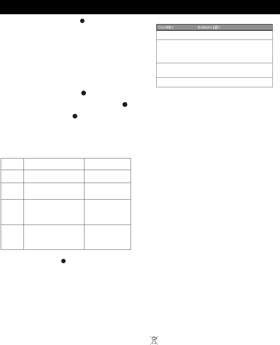
Condition Indicator LED
Slow Blinking Red (will finish within
60 seconds)
Indicator LEDs
Normal Walk Test
Red ON for 3 seconds if Alarm
Yellow ON for 2 seconds if Microwave
event detected
Green ON for 2 seconds if PIR event
detected
Microwave Walk Test
Red ON if Microwave is set too high
Green ON if Microwave is set correctly
OFF if Microwave is set too low
TROUBLESHOOTING
RED LED flashing rapidly during normal operation indicates a trouble
condition. A microwave, PIR, or temperature compensation fault is
present, or a communication error has occured. Supervision errors
and low battery conditions are indicated at the panel.
Solution: Momentarily power down the sensor by removing and
replacing all the batteries. If the trouble does not clear, replace the
sensor.
SPECIFICATIONS
Range: 50’ x 60’ (15 m x 18 m) [installed]
35’ x 40’ (11 m x 12 m) [included]
Batteries: Four 1.5V AA Lithium Batteries (Use only Energizer L91)
Battery Caution: Risk of fire, explosion and burns. Do not
recharge, disassemble, heat above 100° C (212° F), or incinerate.
Dispose of used batteries promptly. Keep away from children.
Microwave Frequency: 24.125 GHz (K-band)
RF Frequency: 345 MHz
PIR White Light Immunity: 6,500 Lux typical
Fluorescent Light Filter: 50 Hz or 60 Hz, switch selectable
Operating Temperature: -20° to 55° C (-4° to 131° F),
5% - 95% relative humidity (non-condensing)
Self-Tests:
Microwave supervision; End-to-End PIR self-test; Temperature
Compensation
Temperature Compensation: Advanced Dual Slope
PIR Fields of View:
Wide Angle Lens (P/N 5-532-439-01)
44 long range zones 12 intermediate zones
6 lower zones 4 look-down zones
Animal Immune Lens (P/N 5-532-489-01)
44 long range zones 36 intermediate zones
18 lower zones 4 look-down zones
Dimensions: 4.93” x 2.93” x 1.68” (12.5cm x 7.5cm x 4.3cm)
Weight: 149.0 g (5.26 oz); Packaged: 205.0 g (7.23 oz)
Accessories:
Optional Lens Kits -
Long Range Curtain Lens Kit 15 m x 3 m / 50’ x 10’ (P/N DT7000-LRLK)
High Security Lens Kit 11 m x 12 m / 35’ x 40’ (P/N DT7000-HSLK)
Pet Alley Lens Kit 11 m x 12 m / 35’ x 40’ (P/N DT7000-PALK)
Mounting Brackets –
SMB-10 Swivel Mount Bracket (P/N 0-000-110-01)
SMB-10C Swivel Mount Ceiling Bracket (P/N 0-000-111-01)
Approval Listings:
FCC
IC
CE, C-Tick, cULus Listed
COMPLIANCE NOTES
• Sensor must be tested once per year.
• Sensor must have a clear line-of-sight to protected area.

5898 Wireless DUAL TEC
®
Motion Sensor - Installation Instructions SP- Americas
PRELIMINARY DRAFT 5/18/09
- 4 -
1
SELECT MOUNTING LOCATION (See
A
)
Additional guidelines for animal immunity:
• Mount the center of the sensor at 2.3 m (7.5 feet) high.
• Set the sensor to the Lowest or Low sensitivity (see step 6a).
• Install Animal Immune lens (5-532-489-01 - see Lens Change
Instructions on page 3).
• Install the look-down mask (see Step 6a).
• Install the sensor where animals cannot come within 1.8 m (6 ft) of
the sensor by climbing on furniture or other objects.
• Aim the sensor away from stairways, furniture or other objects that
can be climbed on by pets.
• TEST the installation site to determine the exact level of attainable
animal immunity.
2 REMOVE THE FRONT HOUSING (SEE
B
)
3
SELECT THE RANGE, SENSITIVITY AND PROTOCOL (SEE
C
)
4 CONNECT THE BATTERIES (SEE
D
)
5 REGISTER THE SENSOR TO THE PANEL
Refer to the control panel’s manual and the programming tool manual
for information on registering wireless devices.
Once you enter the sensor serial number into the panel programming,
select the desired loop for that zone.
Serial #
/ LOOP
Serial #1
/ Loop 1
High Sensitivity
No Animal Immunity Pulse Count 1
Serial #1
/ Loop2
Low Sensitivity / Animal
Immunity [23 kg (50 lb.) / 45
kg (100 lb.)]
Pulse Count 2
Serial #2
/ Loop 1
Low Temperature Trip
When temperature drops
below 7° C ± 2° C
(45° F ± 4° F) for 5 minutes
Low Temp Restoral
When temperature
rises + 2° C
(+ 3° F) above low
temperature trip point
Serial #2
/ Loop 2
High Temperature Trip
When temperature rises
above 35° C ± 2° C
(95° F ± 4° F) for 5 minutes
Low Temp Restoral
When temperature
crops - 2° C
(- 3° F) below high
temperature trip point
6 MOUNT THE SENSOR (SEE
E
)
7 NORMAL WALK TEST– 10 MINUTES
Normal walk test mode activates every time the front cover is closed
and remains active for 10 minutes. For an additional 10 minutes of
walk test time, remove and replace the front cover. In walk test mode,
the LED is always enabled.
Walk through the detection area and observe the LED.
If necessary, adjust the microwave range, pulse count or sensitivity
setting. (For LED activation meaning, refer to the LED Indicator table.)
8 MICROWAVE WALK TEST – 10 MINUTES
1. Set the Microwave Walk Test DIP switch to ON, or toggle it ON and
OFF.
2. Set Range Adjustment potentiometer to 25% and replace the cover.
3. Walk through the detection area and observe the LED.
4. If necessary, adjust the potentiometer until desired detection range
is obtained. (For LED activation meaning, refer to the LED Indicator
table.)
Power Up
Trouble or Anti-Mask Fast Blinking Red (LED Enabled
or Disabled)
Condition Indicator LED
Slow Blinking Red (will finish within
60 seconds)
Indicator LEDs
Normal Walk Test
Red ON for 3 seconds if Alarm
Yellow ON for 2 seconds if Microwave
event detected
Green ON for 2 seconds if PIR event
detected
Microwave Walk Test
Red ON if Microwave is set too high
Green ON if Microwave is set correctly
OFF if Microwave is set too low
TROUBLESHOOTING
RED LED flashing rapidly during normal operation indicates a trouble
condition. A microwave, PIR, or temperature compensation fault is
present, or a communication error has occured. Supervision errors
and low battery conditions are indicated at the panel.
Solution: Momentarily power down the sensor by removing and
replacing all the batteries. If the trouble does not clear, replace the
sensor.
SPECIFICATIONS
Range: 50’ x 60’ (15 m x 18 m) [installed]
35’ x 40’ (11 m x 12 m) [included]
Batteries: Four 1.5V AA Lithium Batteries (Use only Energizer L91)
Battery Caution: Risk of fire, explosion and burns. Do not
recharge, disassemble, heat above 100° C (212° F), or incinerate.
Dispose of used batteries promptly. Keep away from children.
Microwave Frequency: 24.125 GHz (K-band)
RF Frequency: 345 MHz
PIR White Light Immunity: 6,500 Lux typical
Fluorescent Light Filter: 50 Hz or 60 Hz, switch selectable
Operating Temperature: -20° to 55° C (-4° to 131° F),
5% - 95% relative humidity (non-condensing)
Self-Tests:
Microwave supervision; End-to-End PIR self-test; Temperature
Compensation
Temperature Compensation: Advanced Dual Slope
PIR Fields of View:
Wide Angle Lens (P/N 5-532-439-01)
44 long range zones 12 intermediate zones
6 lower zones 4 look-down zones
Animal Immune Lens (P/N 5-532-489-01)
44 long range zones 36 intermediate zones
18 lower zones 4 look-down zones
Dimensions: 4.93” x 2.93” x 1.68” (12.5cm x 7.5cm x 4.3cm)
Weight: 149.0 g (5.26 oz); Packaged: 205.0 g (7.23 oz)
Accessories:
Optional Lens Kits -
Long Range Curtain Lens Kit 15 m x 3 m / 50’ x 10’ (P/N DT7000-LRLK)
High Security Lens Kit 11 m x 12 m / 35’ x 40’ (P/N DT7000-HSLK)
Pet Alley Lens Kit 11 m x 12 m / 35’ x 40’ (P/N DT7000-PALK)
Mounting Brackets –
SMB-10 Swivel Mount Bracket (P/N 0-000-110-01)
SMB-10C Swivel Mount Ceiling Bracket (P/N 0-000-111-01)
Approval Listings:
FCC
IC
CE, C-Tick, cULus Listed
COMPLIANCE NOTES
• Sensor must be tested once per year.
• Sensor must have a clear line-of-sight to protected area.
5898 Wireless DUAL TEC
®
Motion Sensor - Installation Instructions
PRELIMINARY DRAFT 5/18/09
- 5 -
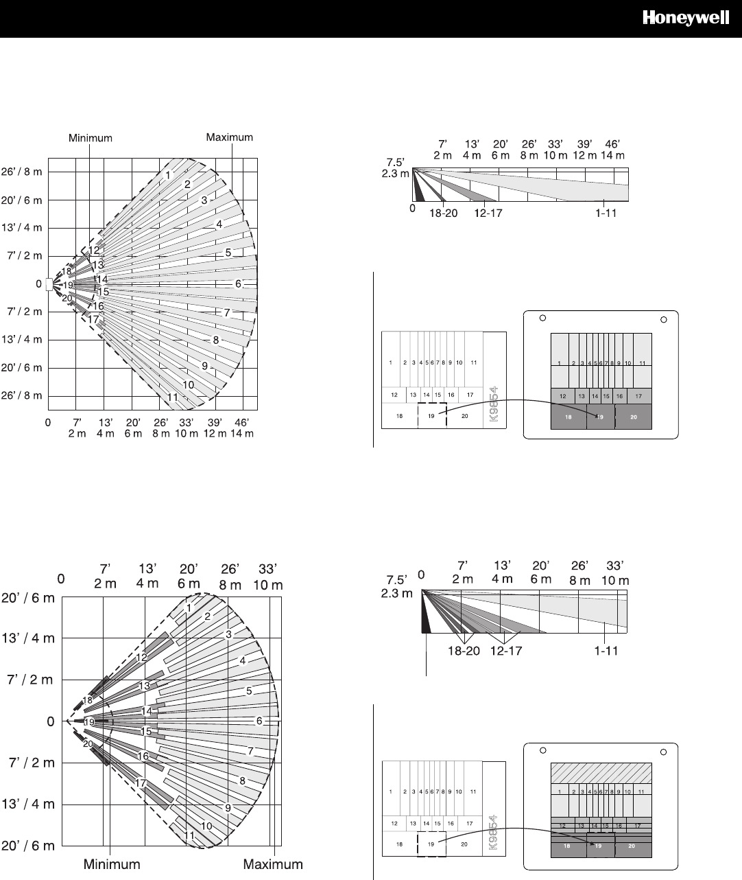
DETECTION PATTERNS / COUVERTURE DE DETECTION / PATRON DE DETECCIÓN
50’ / 15m Wide Angle Lens / Wide Angle Lens / Wide Angle Lens /
(P/N 5-532-439-01 – Installed)
Top View / VUE DE DESSUS / VISTA DESDE ARRIBA
35’ / 11m Animal Immune Lens / Animal Immune Lens / Animal Immune Lens
(P/N 5-532-489-01 – Included)
Top View / VUE DE DESSUS / VISTA DESDE ARRIBA
LENS MASKING
/
LENS MASKING / LENS MASKING /
5-532-439-01
TOP
50FT
LENS MASKI
NG
/
LENS MASKING / LENS MASKING /
5-532-489-01
TOP
25 / 35FT
Side View
/ VUE DE COTE / VISTA LATERAL
Side View
/ VUE DE COTE / VISTA LATERAL
5898 Wireless DUAL TEC
®
Motion Sensor - Installation Instructions
PRELIMINARY DRAFT 5/18/09
- 6 -
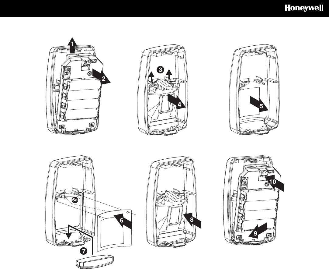
LENS CHANGE INSTRUCTIONS / LENS CHANGE INSTRUCTIONS / LENS CHANGE INSTRUCTIONS / LENS CHANGE INSTRUCTIONS / LENS
CHANGE INSTRUCTIONS

5898 Wireless DUAL TEC
®
Motion Sensor - Installation Instructions
PRELIMINARY DRAFT 5/18/09
- 7 -
5898 Wireless DUAL TEC
®
Motion Sensor - Installation Instructions
PRELIMINARY DRAFT 5/18/09
- 8 -
FCC NOTICE: This equipment has been tested and found to comply with the limits for a Class B digital device, pursuant to Part 15 of the FCC Rules. These limits are designed to provide
reasonable protection against harmful interference in a residential installation. This equipment generates, uses and can radiate radio frequency energy and, if not installed and used in accordance
with the instructions, may cause harmful interference to radio communications. However, there is no guarantee that interference will not occur in a particular installation. If this equipment does
cause harmful interference to radio or television reception, which can be determined by turning the equipment off and on, the user is encouraged to try to correct the interference by one or more of
the following measures:
− Reorient or relocate the receiving antenna.
− Increase the separation between the equipment and receiver.
− Connect the equipment into an outlet on a circuit different from that to which the receiver is connected.
− Consult the dealer or an experienced radio/television technician for help.
The user is cautioned that changes or modifications not expressly approved by Honeywell could void the user’s authority to operate this equipment.
IC NOTICE: This Class B digital device complies with the Canadian RSS-210.
Cet appareil numérique de la Classe B est conforme à la norme CNR-210 du Canada.
This Class B digital device complies with RSS-210 of the IC rules. Operation is subject to the following two conditions: (1) this device may not cause harmful interference, and (2) this device must
accept any interference received, including interference that may cause undesired operation.
Cet appareil numérique de la Classe B est conforme à la norme CNR-210 des règles d’IC. L’utilisation de ce dispositif est autorisée seulement aux deux conditions suivantes ; (1) il ne doit pas
produire de brouillage, et (2) l’utilisateur du dispositif doit être prêt à accepter tout brouillage radioélectrique reçu, même si ce brouillage est susceptible de compromettre le fonctionnement du
dispositif.
2009 Honeywell International Inc. Honeywell and DUAL TEC are registered trademarks of Honeywell International Inc.
All other trademarks are the properties of their respective owners. All rights reserved. Made in China.
For the latest U.S. warranty information, please go to: www.honeywell.com/security/hsc/resources/wa or
Please contact your local authorised Honeywell representative for product warranty information.
Contacter un revendeur Honeywell autorisé pour obtenir des informations sur la garantie de ce produit.
Por favor contacte con su distribuidor Honeywell Security para información sobre la garantía del producto.
P/N P800-01801 Rev A