Ademco 8DL6160RF Wireless keypad User Manual K0903
Honeywell International Inc. Wireless keypad K0903
UserManual.wiki
>
Ademco
>
8DL6160RF User Manual
II with FCC PT 15 Statements
Navigation menu
Upload a User Manual
Namespaces
Wiki Guide
HTML
PDF
Info
Views
User Manual
Discussion / Help
Navigation
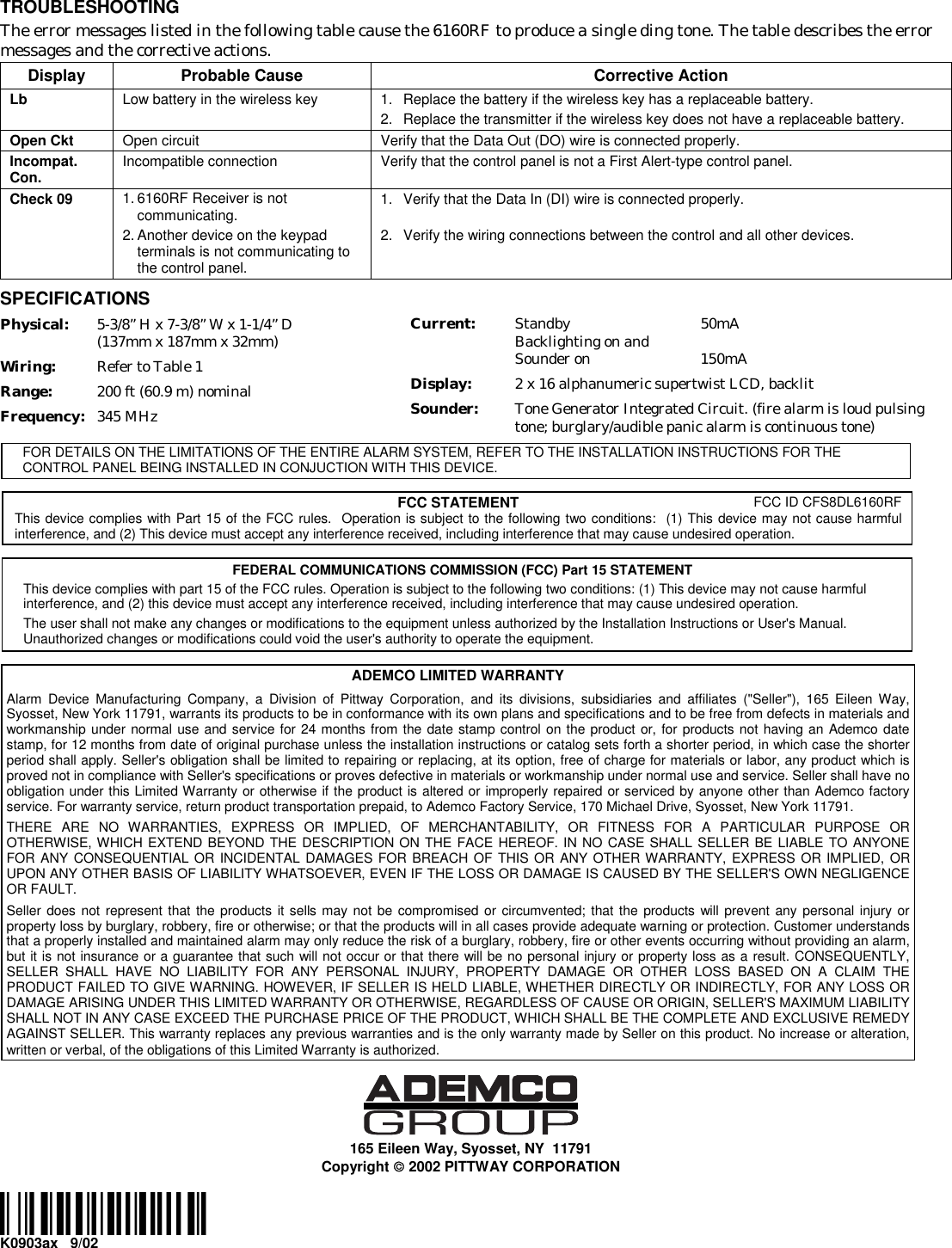
![Preliminary - 6 September 2002 2 INSTALLING THE 6160RF Locate the 6160RF in an area and at a height where it is convenient for user operation. The 6160RF must be at least 10 ft from the control panel to ensure proper operation of the RF receiver. Mounting And Wiring The 6160RF has terminal blocks for connection to power and data wires, and relay contact wires. Removing the keypad’s case back accesses these terminal blocks. The 6160RF can be surface mounted directly to walls, or to a single- or double-gang U.S./Italian style electrical box. Follow these steps to mount and wire the keypad: 1. Detach the case back by pushing up into one of the two slots at the bottom of the keypad with the blade of a small screwdriver (this will push in the release snap), then pull that side of the case back away. Repeat for the other side. Refer to Figure 1 for location of the case back release snaps. ARMEDREADYMOUNTINGRELEASESNAPSNOTE:TO REMOVE REAR COVERPUSH IN THE TWO MOUNTINGSNAPS LOCATED ALONG THE BOTTOM OF THE KEYPADAND LIFT COVER UP.6164RF-003-V0 Figure 1. Removing the Case Back 2. Pass the wiring from the control panel through the opening in the case back. (see the control panel’s instructions for proper run lengths.) a. If surface wiring is being used, wiring may be routed through the top or the bottom left-side breakout in the case back. See Figure 2. The breakouts must be punched out using a screwdriver before mounting the case back. b. If desired, wires may be strain-relieved to the wire tie point on the inside of the case back with a tie wrap (not supplied). 3. Mount the case back to a wall or to an electrical box using the 25mm-long self-tapping screws supplied (mollies for drywall are not supplied). Note: If you wish to tamper-protect the keypad for removal from the wall, use an additional mounting screw in the tamper hole in the case back (see Figure 2 for location). 4. Connect the power and data wires from the control panel to the terminals on the 6160RF as indicated Figure 3 and Table 1. G6160RF-002-V0Y+TAMPERSWITCHWIRING TERMINALS(TO CONTROL PANEL)++++ Figure 3 - 6160RF Wiring Details Table 1 - Wiring Table Keypad Control Panel Wire Color ▲ G Data In Green - -Aux Pwr (GND) Black + +Aux Pwr Red Y Data Out Yellow 5. Re-attach the keypad to the mounted case back. Attach the top of the keypad first, and then press the bottom section down until it snaps into place securely. 6. Peel off protective film on the LED panel and install the keypad labels as required. 6160RF PROGRAMMING Entering Program Mode Press the [1] and [3] keys simultaneously for a few seconds within 30 seconds after applying power or within 30 seconds after removing the case back. The current keypad address CON ADDRESS = XX will be displayed. Press the [✳] key. Programming Operations Once you have entered the Program mode, you may advance between prompts by pressing the [✳] key. This will also store displayed information. Programming the 6160RF Note: Refer to the control panel’s installation instructions for the acceptable keypad and receiver addresses. • If you are using a wireless key in High-Security mode (e.g.;5804E) in the control panel, it will occupy one of the devices in the 6160RF. • When operating the system in High-Security mode, only encrypted wireless keys will function.](https://usermanual.wiki/Ademco/8DL6160RF/User-Guide-273091-Page-2.png)
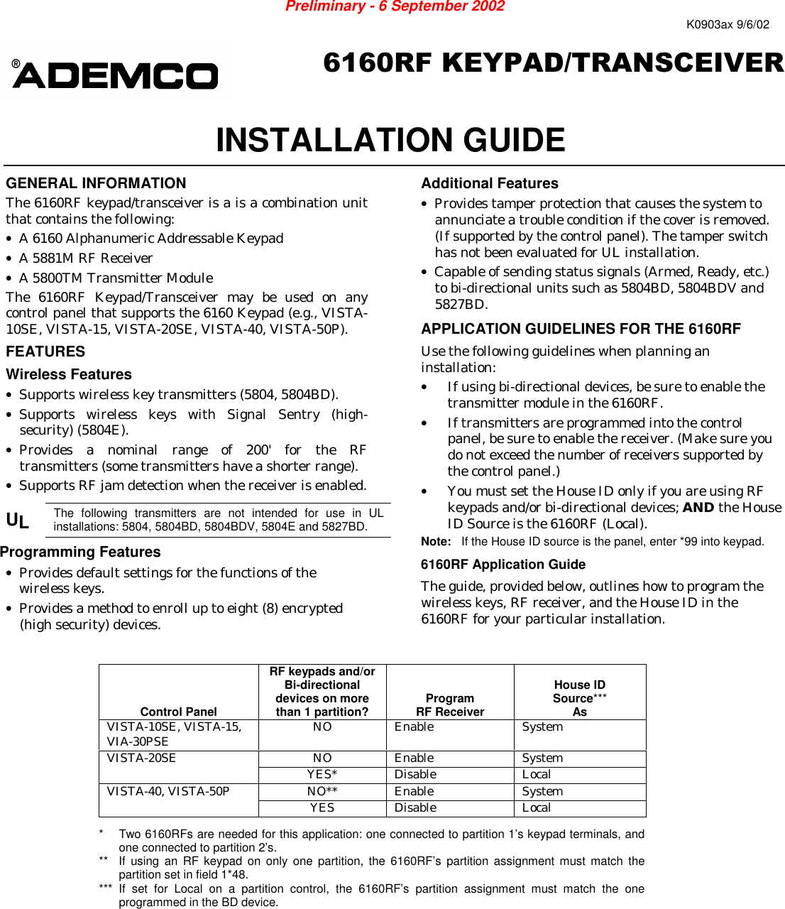
![3 STEP DESCRIPTION DISPLAY CHOICES 1. Enter the program mode by pressing the [1] and [3] keys simultaneously for a few seconds within 30 seconds after applying power or within 30 seconds after removing the case back. (Keypad Address) Enter the two digit keypad address. Press the [✳] key to continue. '32%((6)77= <<01-31 2. (Receiver Enable) Enter [1] to enable, or [0] to disable Receiver. Enable the receiver if RF transmitters or wireless keypads are programmed into the control. Press the [✳] key to continue. 6)')-:)632?= 3**A 1= ON 0 = OFF 3. If receiver is enabled, enter the two digit receiver address. (01-30) Press the [✳] key to continue. 6)'%((6)77= << 01-30 4. (Transmitter Enable) Enter [1] to enable, or [0] to disable. Enter [1] if bi-directional devices are being used. Note: If the House ID source is the System, and more than one 6160RF is used, make sure only one has the Transmitter Module enabled. Press the [✳] key to continue. 86%271-88)632?= 3**A 1= ON 0 = OFF 5. (House ID) Enter 99 (System) to use the House ID programmed into the control panel Enter 01-31 (Local) to use the House ID programmed into the 6160RF. Notes: (1) If the House ID Source is the System, RF Keypads and bi-directional units MUST match the House ID programmed into the panel. (2) If the House ID Source is Local, the RF Keypads and bi-directional units MUST match the House ID programmed into the 6160RF. Press the [✳] key to continue. ,397)-(= <<01-31 = Local 99 = System 6. (Enable High Security mode) Enter [1] to select High Security Mode Note: If this mode is enabled, the 6160RF will only recognize encrypted devices. Press the [✳] key to continue. ,-+,7)'96-8=3**?= 32A1= Enable 0 = Disable 7. (Delete High Security Devices) Press the [✳] key to skip this prompt and exit Program Mode. Note: If you need to delete encrypted devices refer to the Deactivating High Security Devices section. ()0)8)():-')7#1= YES 0 = NO ACTIVATING HIGH SECURITY DEVICES This following procedure should be followed if using High-Security (encrypted) devices. STEP DESCRIPTION 1. Put the control panel in Go/ No Go Test mode. (See the Installation Guide for the panel being installed.) 2. Follow the instruction provided with the wireless device to for installing the High-security (encrypted) device. 3. The 6160RF will momentarily display the serial number of the device. 4. Disable the Go/ No Go Test mode and follow the normal procedure for programming the device into the control panel (refer to the Installation Instructions for the device that you are programming). DEACTIVATING HIGH SECURITY DEVICES This mode gives you the ability to disable all individual wireless keys that have been directly programmed into the 6160RF. This is particularly useful if a user loses a wireless key. ! High-Security (encrypted) devices must also be deleted from the panel. Once High-Security (encrypted) devices have been deleted, the devices will no longer function. STEP DESCRIPTION DISPLAY CHOICES 1. Enter the keypad's local program mode within 60 seconds of power-up by pressing and holding down the [1] and [3] keys at the same time for 3 seconds. The current keypad address will be displayed with the cursor under the "tens" digit. Press the [✱] key to continue. '32%((6)77= <<01-312. (Delete High Security Devices) Press the [1] key to remove all high-security (encrypted) devices. Press the [✱] key to continue. ()0)8)():-')7#23?==)7A 1= YES 0 = NO3. If YES was selected in Step 2 the unit will display a confirm request to delete the stored high security device. Press the [1] key to accept, followed by the [✳] key to exit the programming mode. %6)=39796)#23?==)7A 1= YES 0 = NO](https://usermanual.wiki/Ademco/8DL6160RF/User-Guide-273091-Page-3.png)