Ademco 8DLLYNXTOUCH1 Wireless Control / Communicator User Manual 800 06834 ii
Honeywell International Inc. Wireless Control / Communicator 800 06834 ii
UserManual.wiki
>
Ademco
>
8DLLYNXTOUCH1 User Manual
>
Installers Manual
Contents
1.
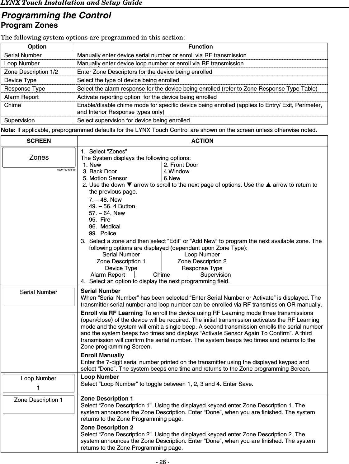
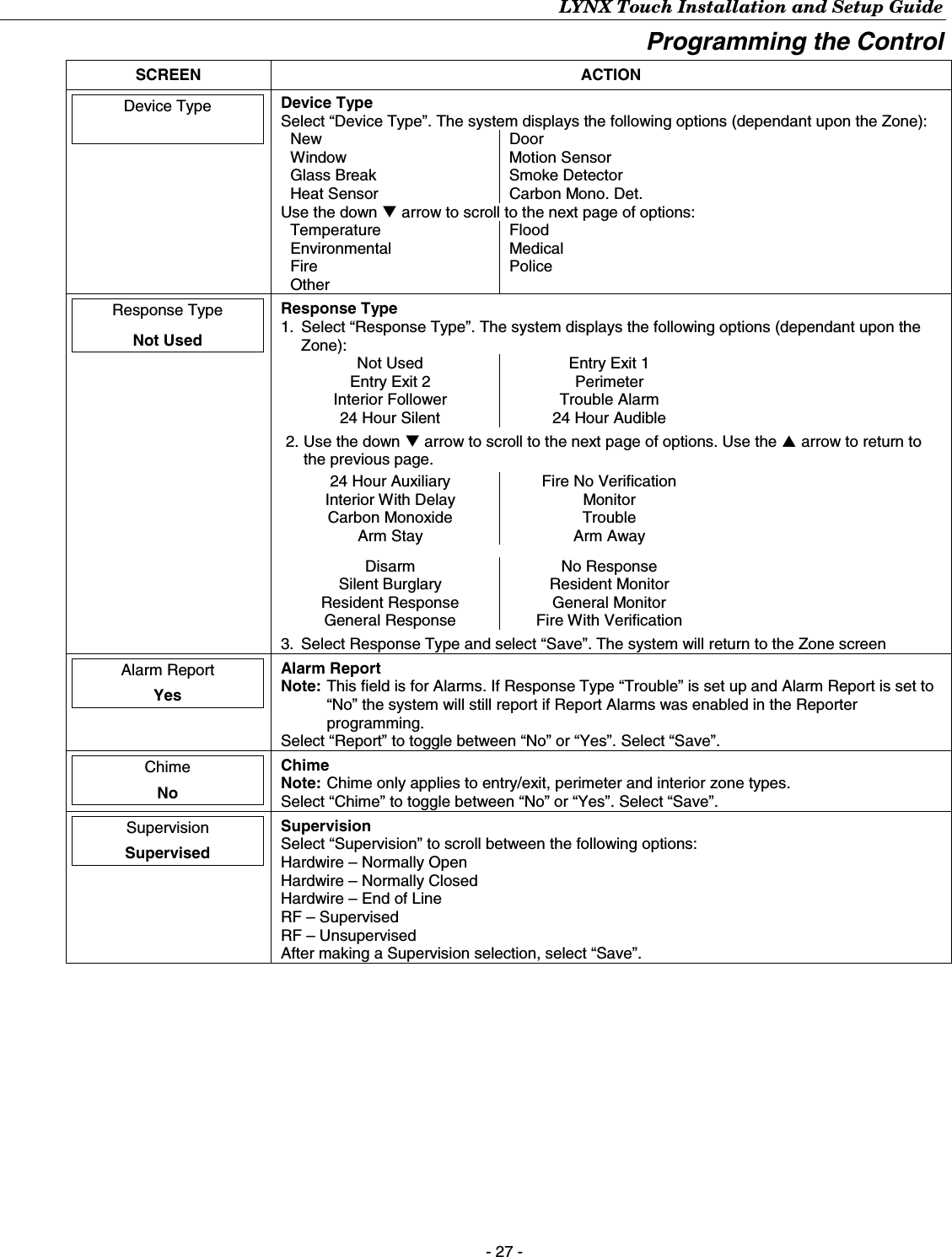
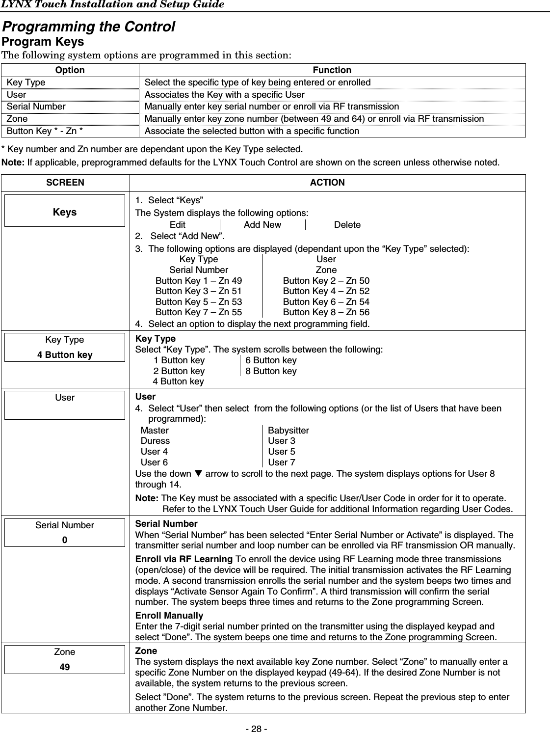
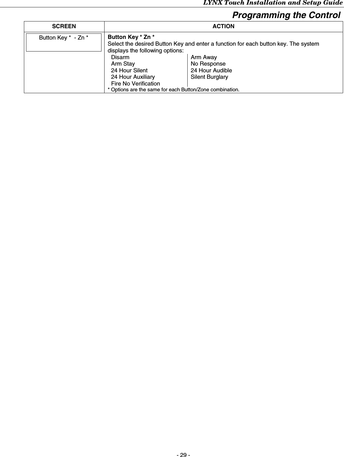
Installers Manual
2.
Users Manual
Installers Manual
Navigation menu
Upload a User Manual
Namespaces
Wiki Guide
HTML
PDF
Info
Views
User Manual
Discussion / Help
Navigation
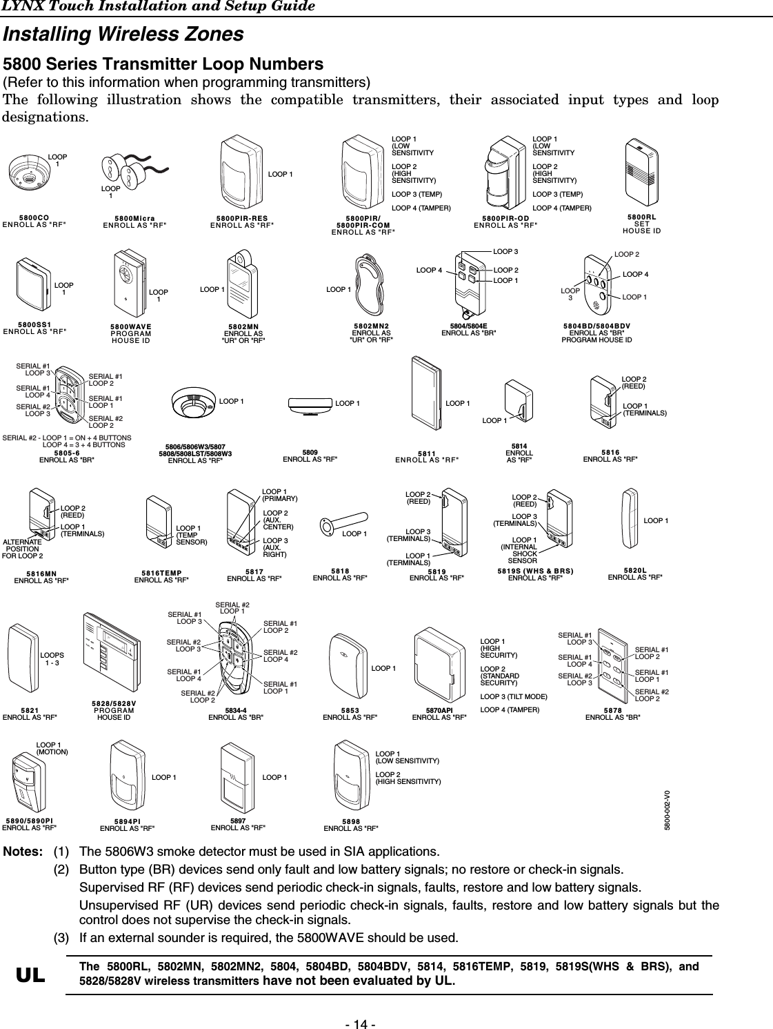
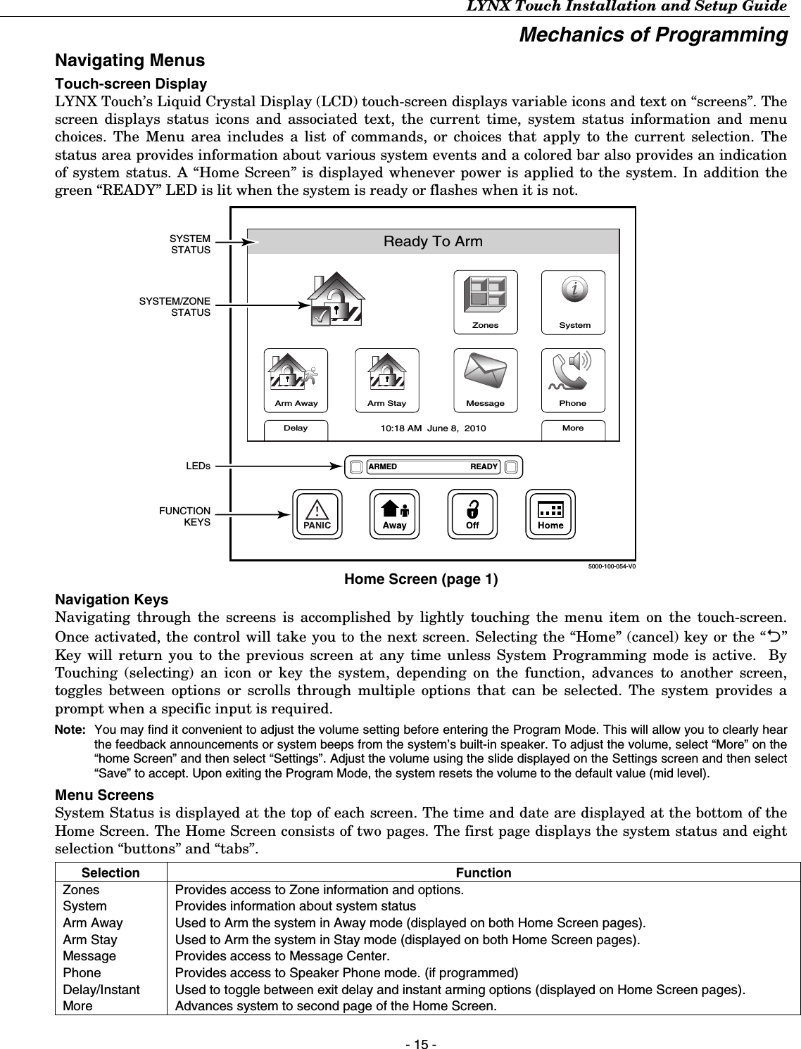
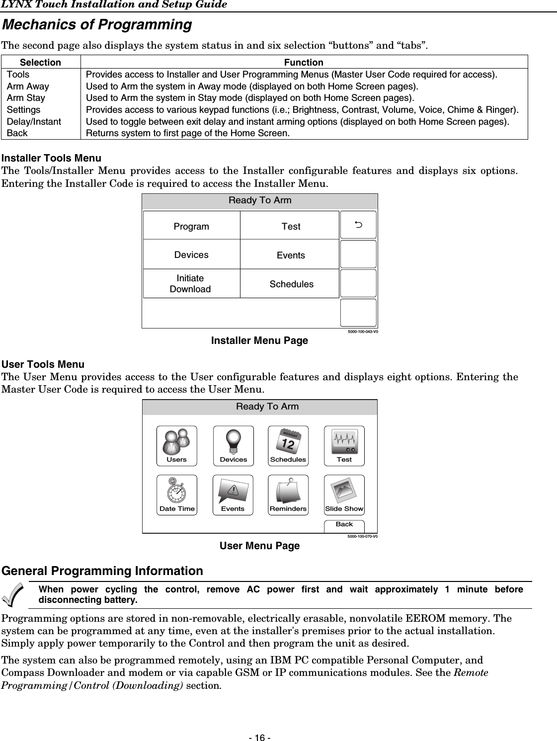
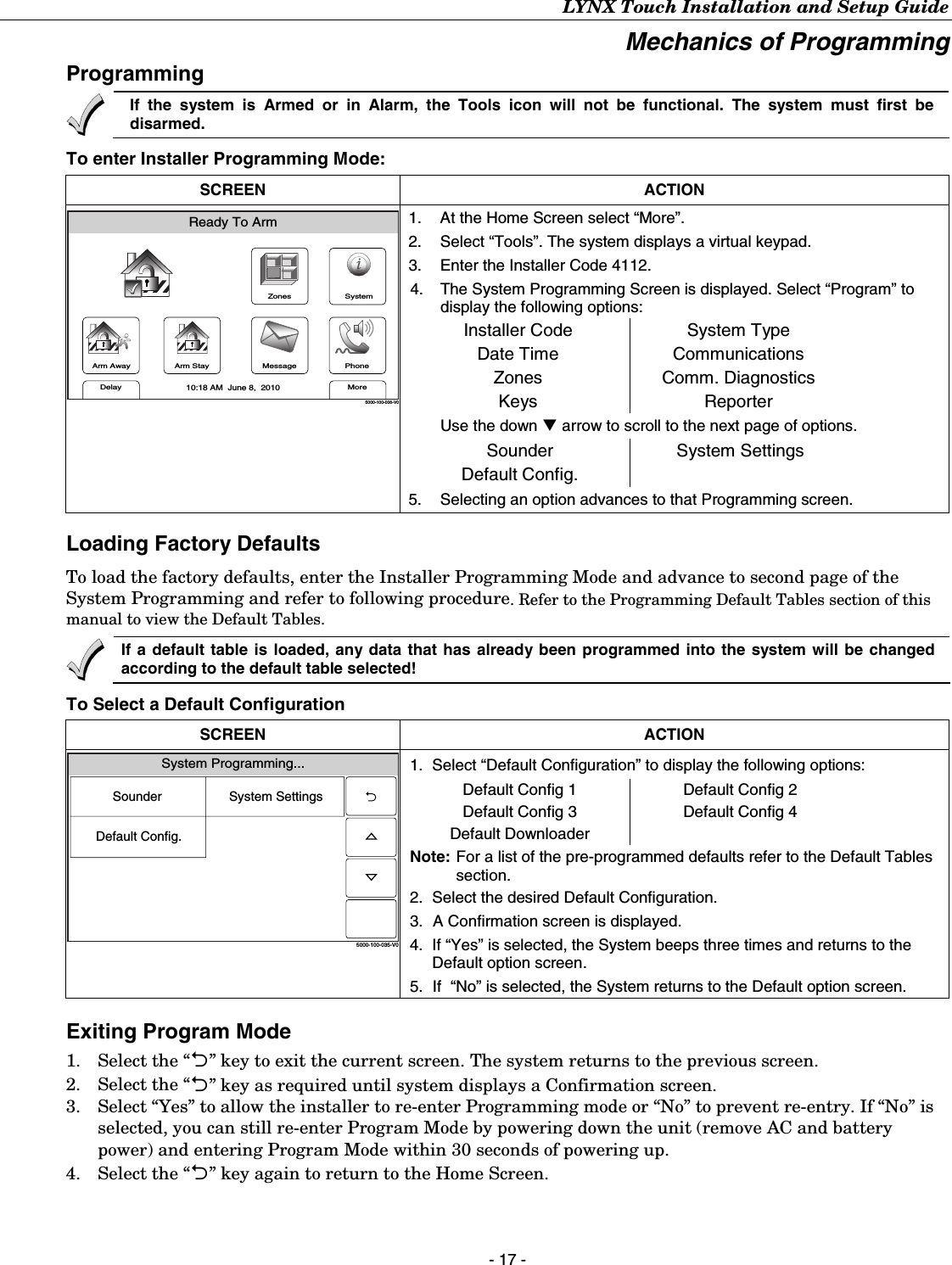
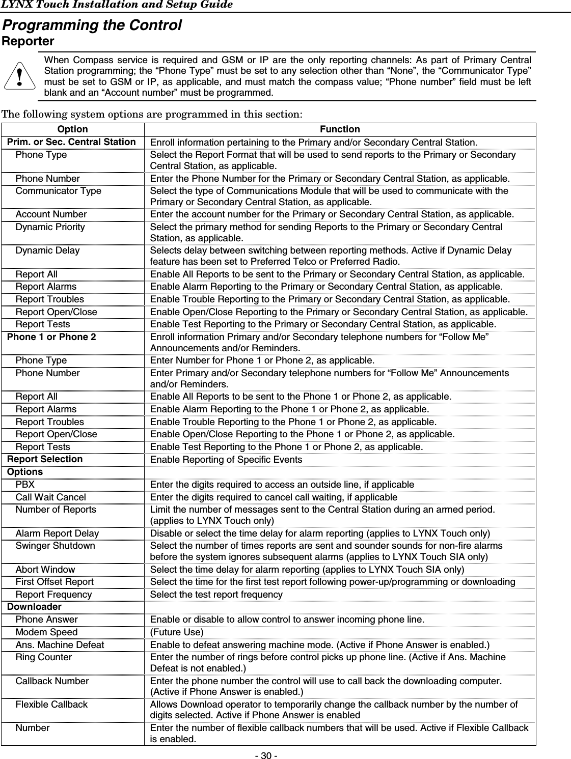
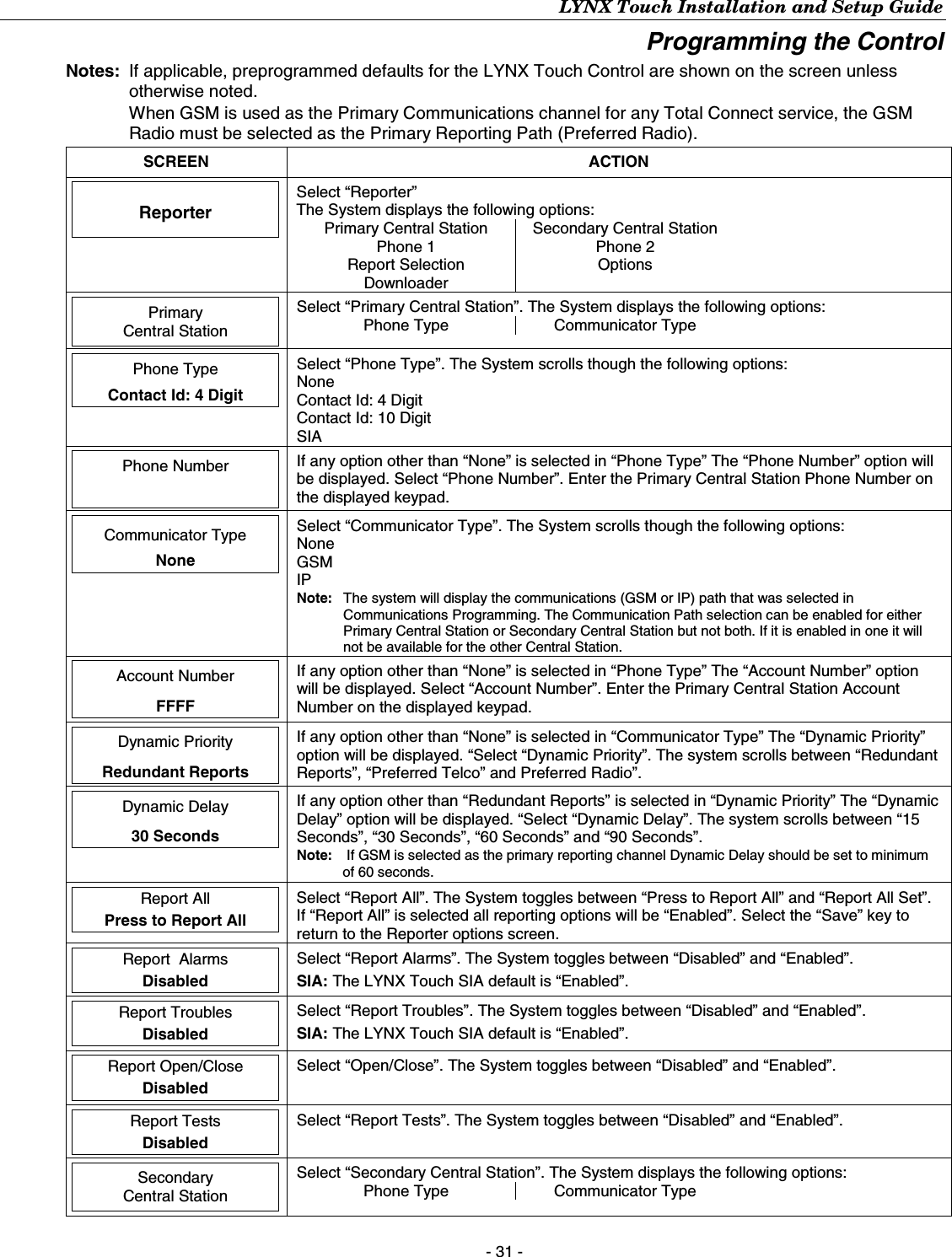
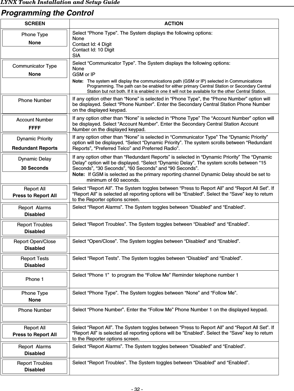
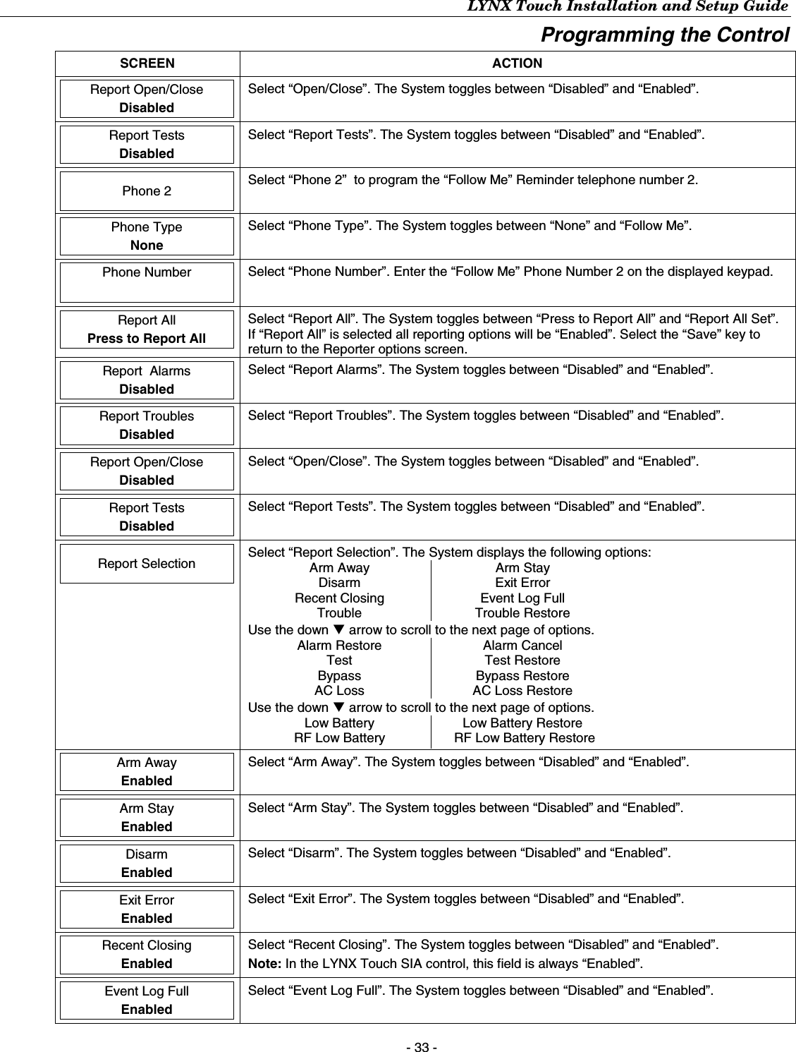
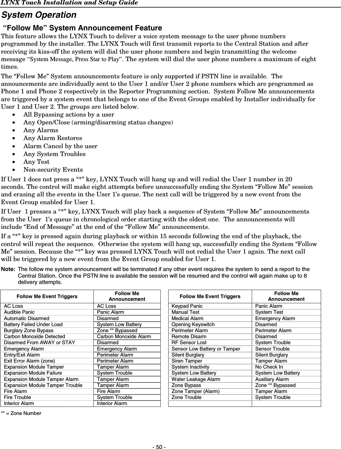
![LYNX Touch Installation and Setup Guide - 53 - System Operation UL Audio alarm verification has not been evaluated by UL. Audio Alarm Verification (Two-Way Voice Feature) This feature allows the central station operator to listen, talk to or conduct a two-way conversation with an individual(s) at the premises. It also assists the operator in gathering information about the nature and location of the alarm that may be helpful in responding to police and fire departments. All LYNX Touch control panels are capable of supporting the Two-Way Voice feature. The LYNX Touch does not make system announcements when the Two-Way voice feature is active. Activation Fire and CO alarms will prevent the LYNX Touch from starting an AAV session. A new Fire or CO alarm will end an AAV session that is in progress. The LYNX Touch sends the “alarm message” followed by a “Listen-in-to-Follow message” (Contact ID® code 606) to the Central Station. The Listen-in-to-Follow message causes the Central Station’s digital receiver to temporarily hold the phone line for approximately 1-minute. When the LYNX Touch receives the “kissoff” from the central station, indicating that the alarm message has been received, the Two-Way Voice (AAV) feature is activated in the (default) “Listen Mode” and sirens and keypad sounds are discontinued. The LYNX Touch transmits a beep acknowledgment to the Central Station, once per second. The beep alternates between two tones and indicates that the LYNX Touch is waiting for a session command from the Central Station operator. Once a command is issued the beep acknowledgement is discontinued, however, if a command is not issued within two minutes the system will “time out” and the call will be terminated. Operator Commands The Central Station operator begins the session, which last 5 minutes, by entering one of the valid AAV commands shown in the table below. The session may be extended 5 minutes, without changing the operating mode, by pressing the [7] key on the touch-tone phone. Selecting another operating mode also resets the session an additional 5 minutes. During the last minute of the 5 minute, session, the LYNX Touch generates two beeps every 30 seconds to alert the Central Station operator that the session is about to time out. The Central Station operator may then extend the session by pressing the [7] key on the touch-tone phone. If the session is not extended the phone line is disconnected, and the session is ended. Sessions may be ended at any time by pressing the [9] key on the touch-tone phone. The AAV modes are described as follows: Note: When entering AAV commands make sure the Central Station receiver has been disconnected from the phone line, otherwise AAV commands may not go through. Key Function 1 Talk Mode: Pressing the [1] key on the touch tone phone, enables one-way voice communication from the central station to the violated premises, and allows the operator to talk communicate through the LYNX Touch speaker. In this mode the ARMED (red) and READY (green) LEDs blink alternately. 2 VOX (Voice) Mode: Pressing the [2] key on the touch-tone phone, enables two-way voice communications between the central station and the violated premises. In this mode the ARMED (red) and READY (green) LEDs blink alternately. 3 Listen Mode: Pressing the [3] key on the touch-tone phone, enables one-way audio from the violated premises to the central station. The Listen Mode is the start up default mode of the voice feature and allows the operator to listen through the LYNX Touch microphone. This mode does not affect the existing LED pattern. 7 Extends the session 5 minutes without changing its operating mode. 9 Ends the session and disconnects the phone line.](https://usermanual.wiki/Ademco/8DLLYNXTOUCH1.Installers-Manual/User-Guide-1430257-Page-53.png)