Ademco 8DLLYNXTOUCH1 Wireless Control / Communicator User Manual 800 06894 ug
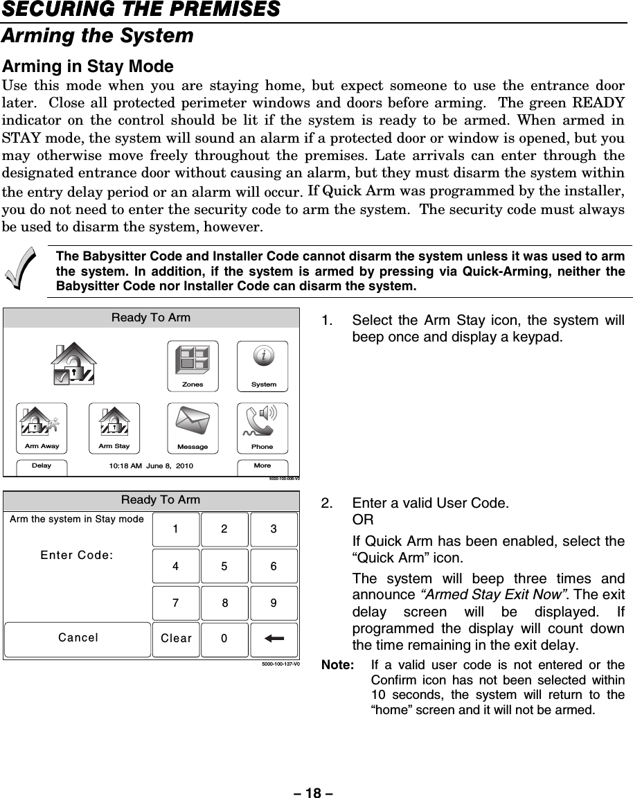
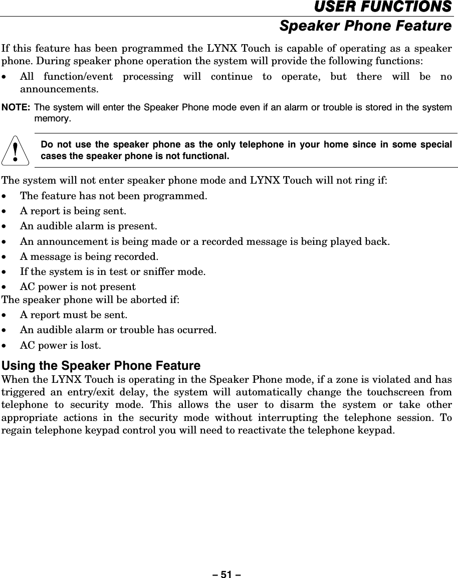
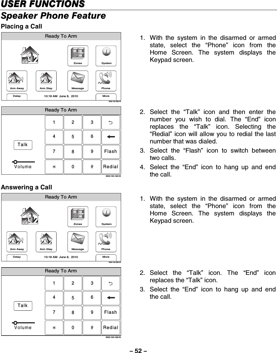
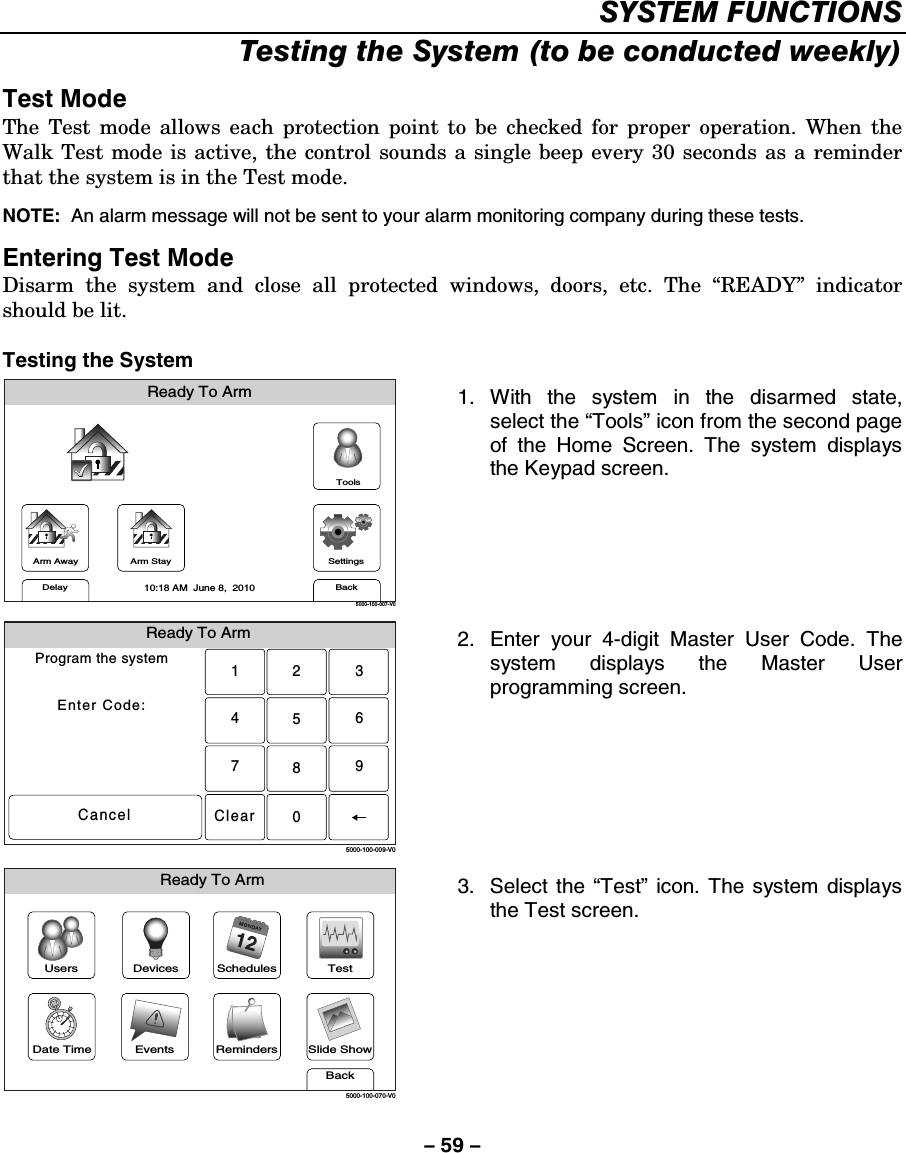
Honeywell International Inc. Wireless Control / Communicator 800 06894 ug
UserManual.wiki
>
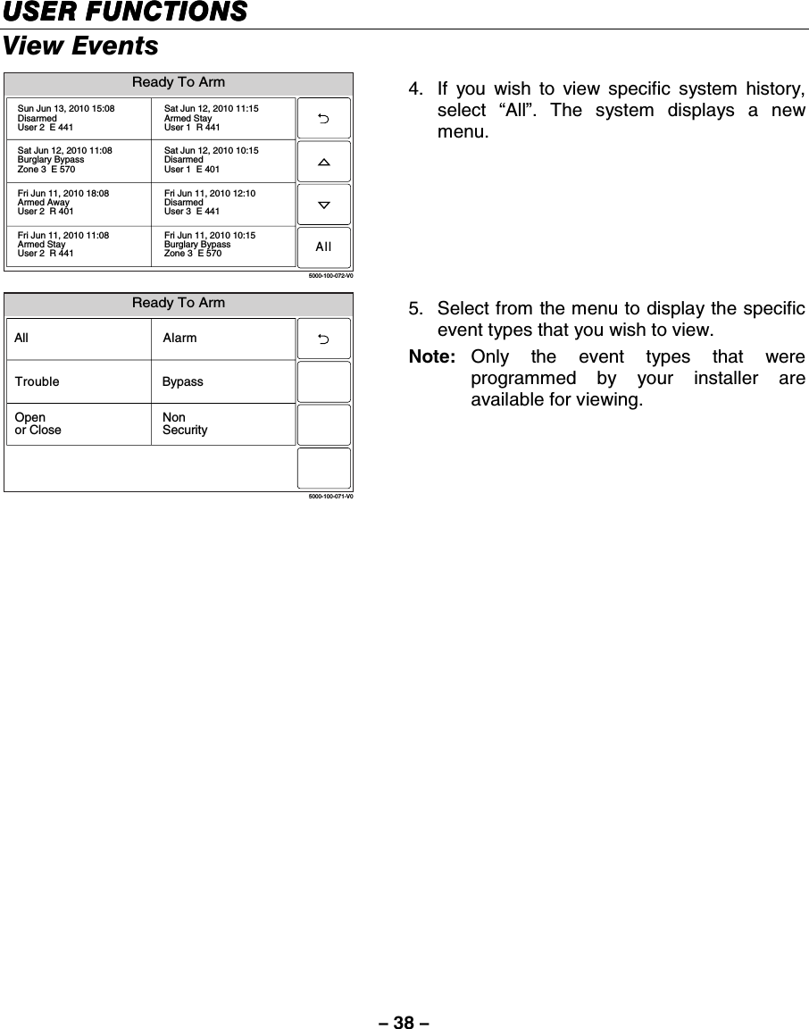
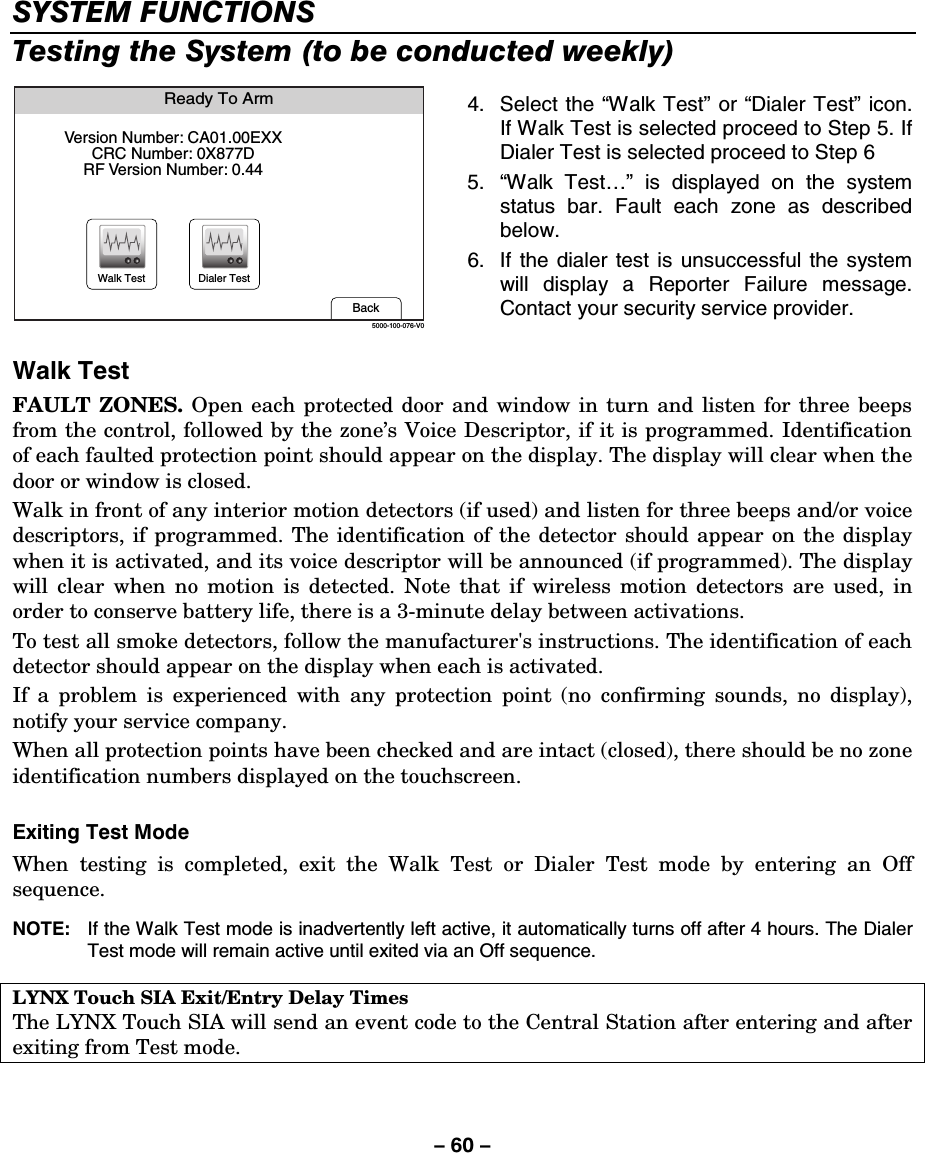
Ademco
>
8DLLYNXTOUCH1 User Manual
>
Users Manual
Contents
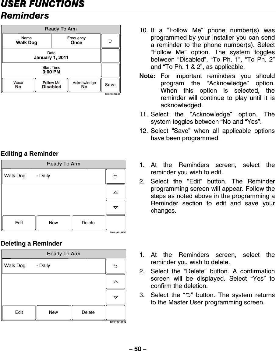
1.
Installers Manual
2.
Users Manual
Users Manual
Navigation menu
Upload a User Manual
Namespaces
Wiki Guide
HTML
PDF
Info
Views
User Manual
Discussion / Help
Navigation
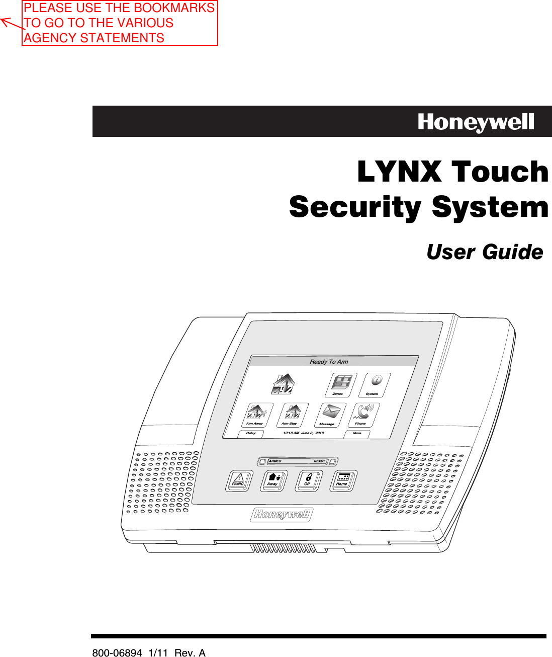

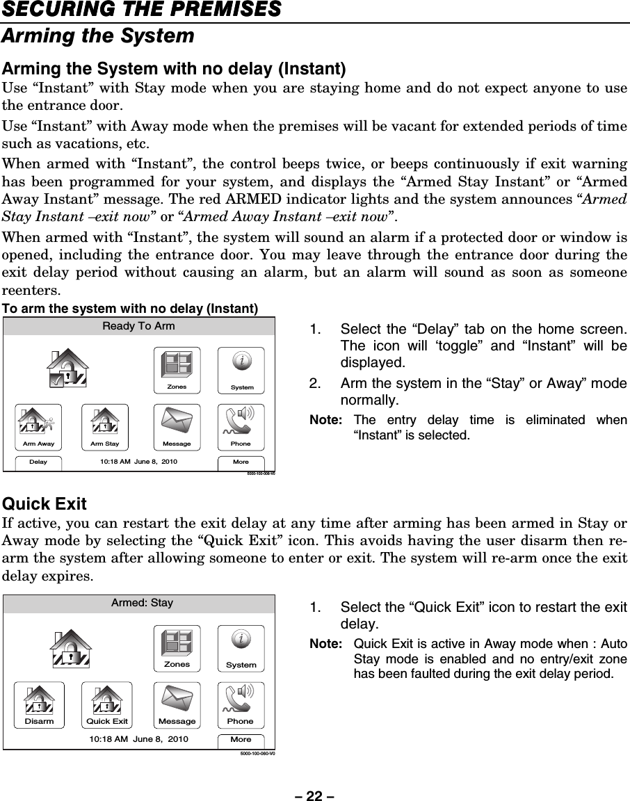
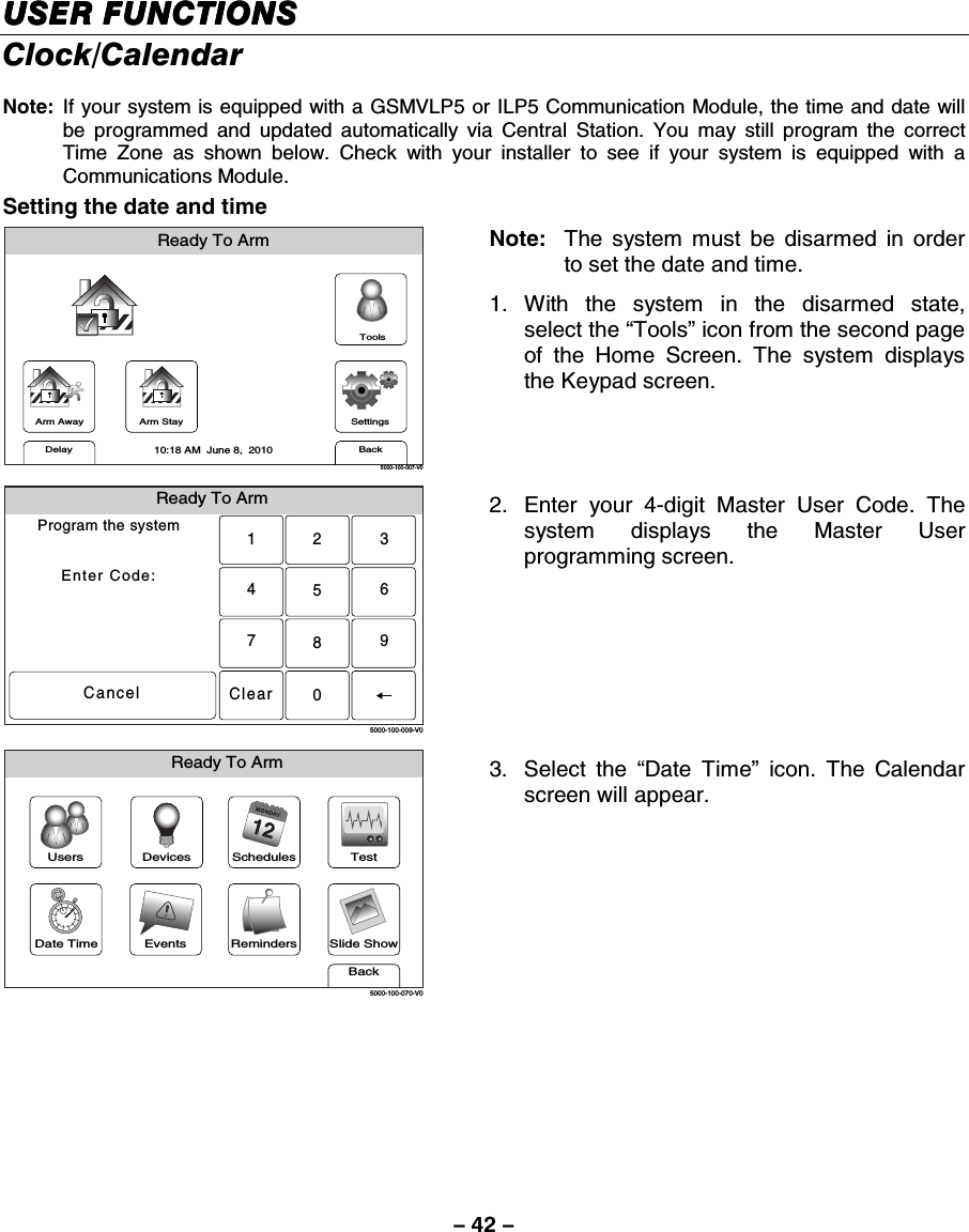
![– 17 – SECURING THE PREMISESSECURING THE PREMISESSECURING THE PREMISESSECURING THE PREMISES System Status General Information Before arming your system, all protected doors, windows, and other protection zones must be closed or bypassed (see the BYPASSING PROTECTION section). READY LED: The green READY indicator on the control will be lit if the system is ready to be armed. If blinking, the system is not ready. NOTE: The phrases shown in brackets are variable, and are announced only if appropriate in the current state of the system. Depending on the current state of the system the following phrases may be heard: fire alarm [zone voice descriptors] carbon monoxide alarm [zone voice descriptors] alarm [zone voice descriptors] fire fault [zone voice descriptors] carbon monoxide fault [zone voice descriptors] fault [zone voice descriptors] low battery [zone voice descriptor] system low battery check system AC loss zones bypassed chime VOLUME LEVEL: The volume level of system announcements can be increased or decreased. Refer to the MESSAGE RECORDING/PLAYBACK section for the procedure. System Can Be Armed The READY LED will be lit steadily once all protection zones have been closed or bypassed. You may now arm the system.](https://usermanual.wiki/Ademco/8DLLYNXTOUCH1.Users-Manual/User-Guide-1430258-Page-17.png)
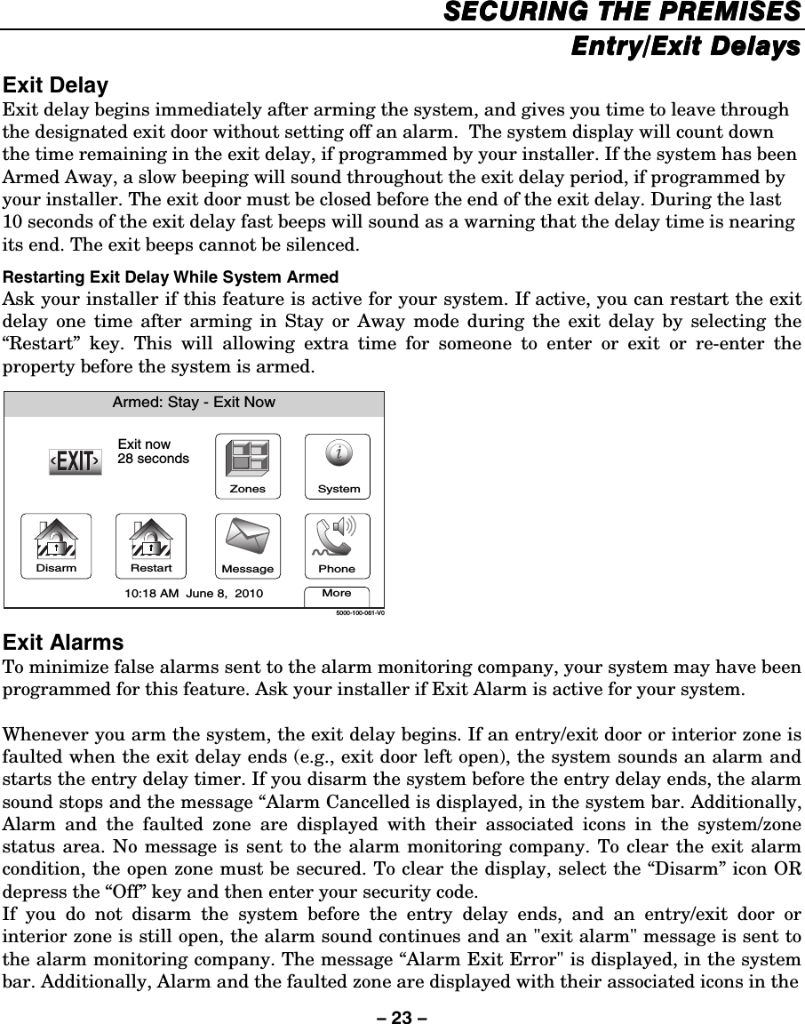
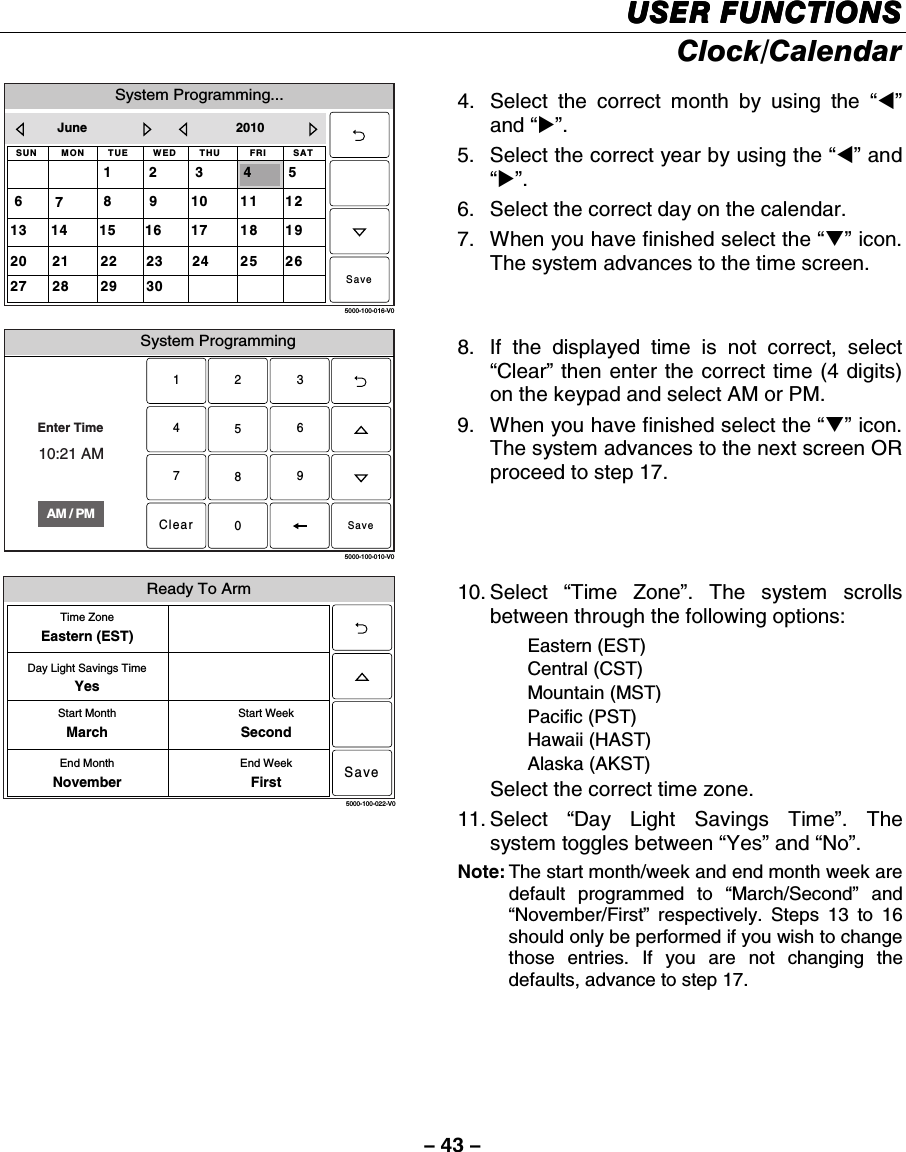
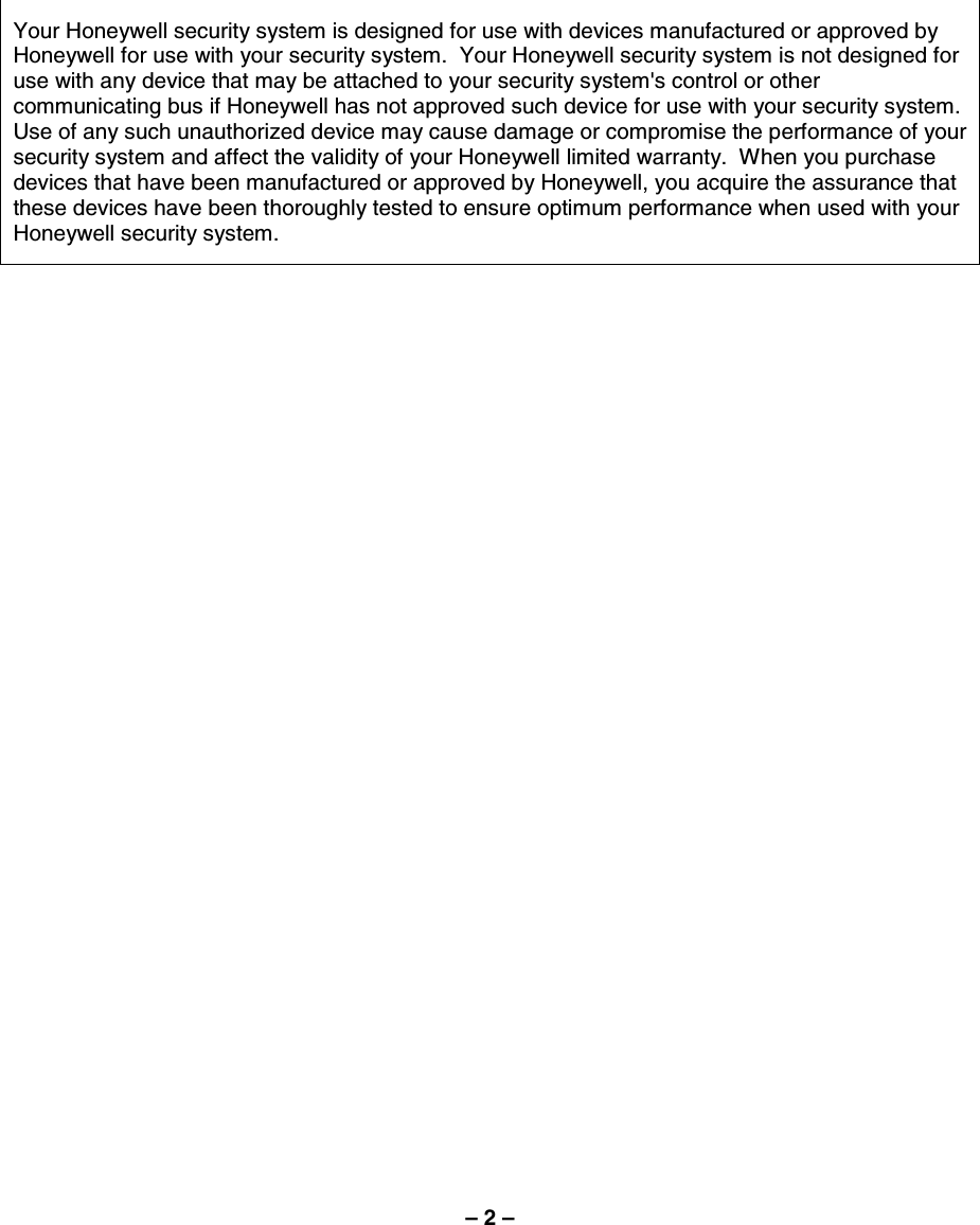
![– 54 – USER FUNCTIONSUSER FUNCTIONSUSER FUNCTIONSUSER FUNCTIONS Remote Phone Control Feature Remote Phone Control Commands Enter User Code (within eight seconds). Upon entering remote phone control mode the Lynx will announce “System, enter code”. To remotely disarm system:........................................................... User Code + [1] To remotely arm in AWAY mode: .................................................. User Code + [2] To remotely arm in STAY mode: ................................................... User Code + [3] To remotely arm in AWAY or STAY mode with no delay:.............. User Code + [2] or [3] + [0] To remotely Bypass zones: ........................................................... User Code + [6] + zone no. To remotely activate Forced Bypass: ............................................ User Code + [6] + [#] To remotely check system status:.................................................. [✻] To end remote phone session: Hang Up or ................................. User Code + [9] Notes: (1) Check with your installer to see if the Forced Bypass mode has been enabled. (2) When bypassing zones, make sure a confirmation beep sounds for each zone that has been bypassed.](https://usermanual.wiki/Ademco/8DLLYNXTOUCH1.Users-Manual/User-Guide-1430258-Page-54.png)
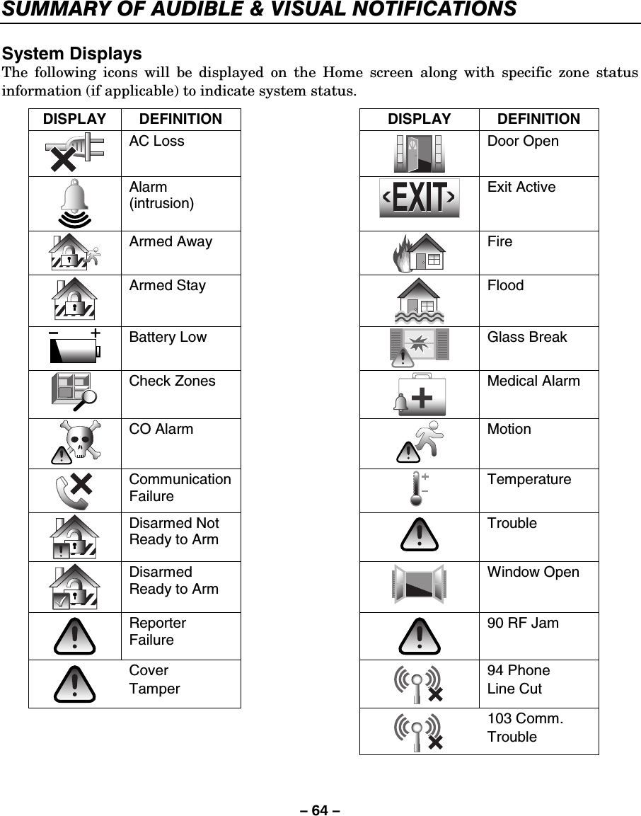
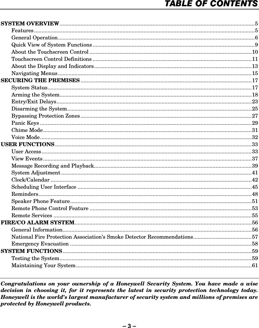
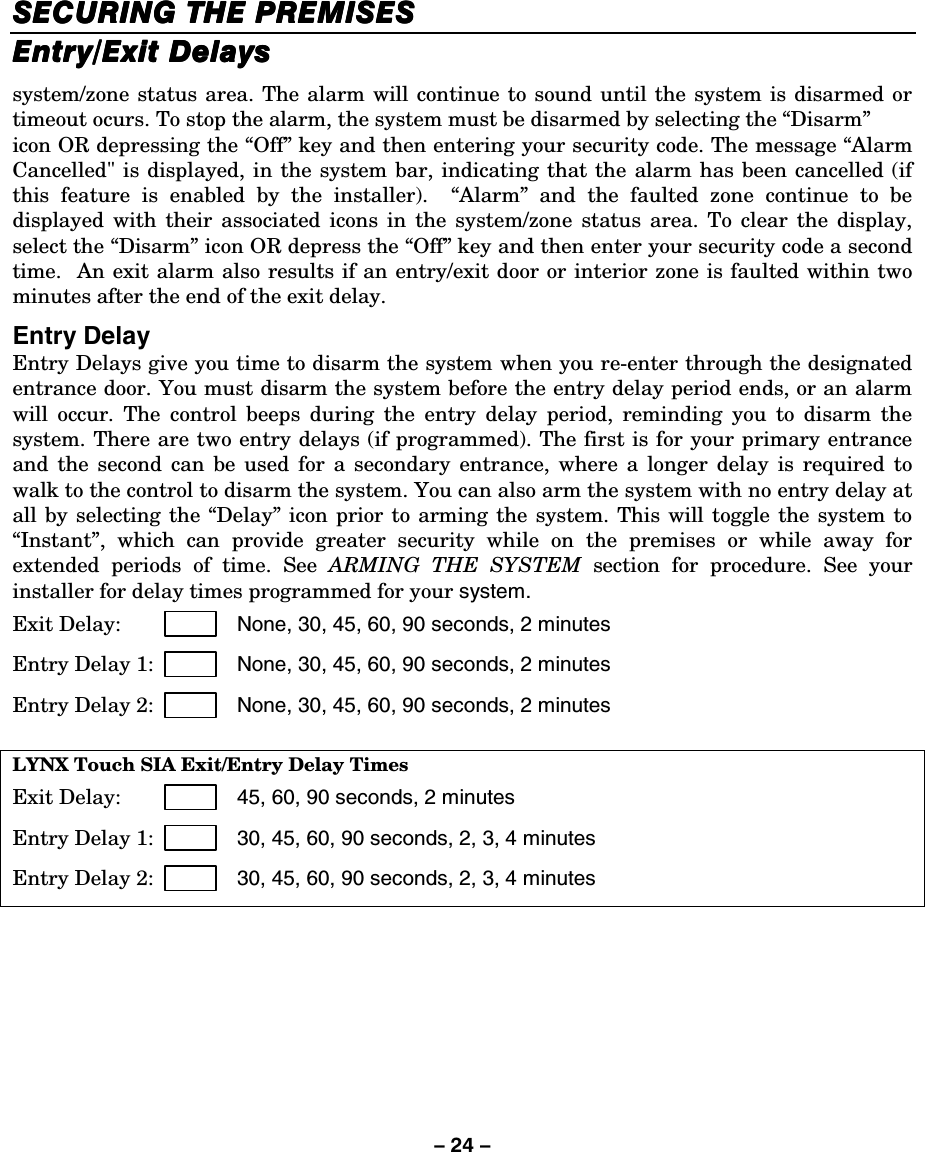
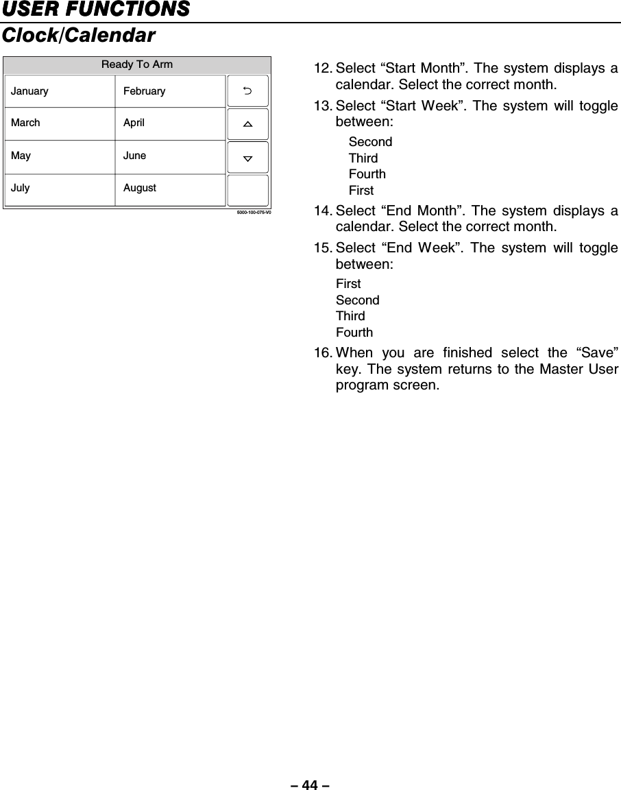
![– 63 – SUMMARY OF AUDIBLE & VISUAL NOTIFICATIONS SOUND CAUSE ANNOUNCEMENT* INTERRUPTED FIRE ALARM (3 beeps) OR CARBON MONOXIDE ALARM (4 beeps) fire alarm + zone voice descriptor OR Carbon monoxide alarm + zone voice descriptor (Voice descriptor is interlaced with the sounder and sounds every 45 seconds) CONTINUOUS BURGLARY/AUDIBLE EMERGENCY ALARM alarm + zone voice descriptor (Voice descriptor is interlaced with the sounder and sounds every 45 seconds) ONE SHORT BEEP (not repeated) a. SYSTEM DISARM b. SYSTEM ARMING ATTEMPT WITH AN OPEN ZONE. c. BYPASS VERIFY a. disarmed–ready to arm b. disarmed–not ready to arm c. zones bypassed ONE SHORT BEEP (once every 45 secs) a. SYSTEM IS IN TEST MODE b. LOW BATTERY AT A TRANSMITTER c. SYSTEM LOW BATTERY d. FAIL TO COMMUNICATE a. no announcement b. low battery + zone voice descriptor c. system low battery d. check system TWO SHORT BEEPS ARM AWAY armed away [instant] – exit now THREE SHORT BEEPS a. ARM STAY OR INSTANT b. ZONE OPENED WHILE SYSTEM IS IN CHIME MODE. a. armed stay [instant] – exit now b. zone voice descriptor RAPID BEEPING a. TROUBLE b. MEMORY OF ALARM a. fault + zone voice descriptor b. fire alarm or alarm + zone voice descriptor SLOW BEEPING a. ENTRY DELAY WARNING b. EXIT DELAY WARNING a. disarm system now b. armed [away] [instant] – exit now Additional Announcements: The system will announce the following primary messages, depending on the system’s status at the time: • Disarmed–Ready to Arm [check system] • Disarmed [not ready to arm] • Armed [away] [stay] [instant] [check system] [exit now] The system will announce the following secondary messages, depending on the system’s status at the time: • Fire Alarm + zone voice descriptor • Alarm + zone voice descriptor • Carbon Monoxide Alarm + zone voice descriptor • Carbon Monoxide Fault + zone voice descriptor • Fire Fault + zone voice descriptor • Fault + zone voice descriptor Alarm + zone voice descriptor • Low Battery + zone voice descriptor Fire Fault + zone voice descriptor • System Low Battery • Check System • AC Loss • Zones Bypassed • Chime Note: If there are no secondary messages, the primary status messages will be announced.](https://usermanual.wiki/Ademco/8DLLYNXTOUCH1.Users-Manual/User-Guide-1430258-Page-63.png)