Ademco 8DLLYNXTOUCH1 Wireless Control / Communicator User Manual 800 06894 ug
Honeywell International Inc. Wireless Control / Communicator 800 06894 ug
Ademco >
Contents
- 1. Installers Manual
- 2. Users Manual
Users Manual
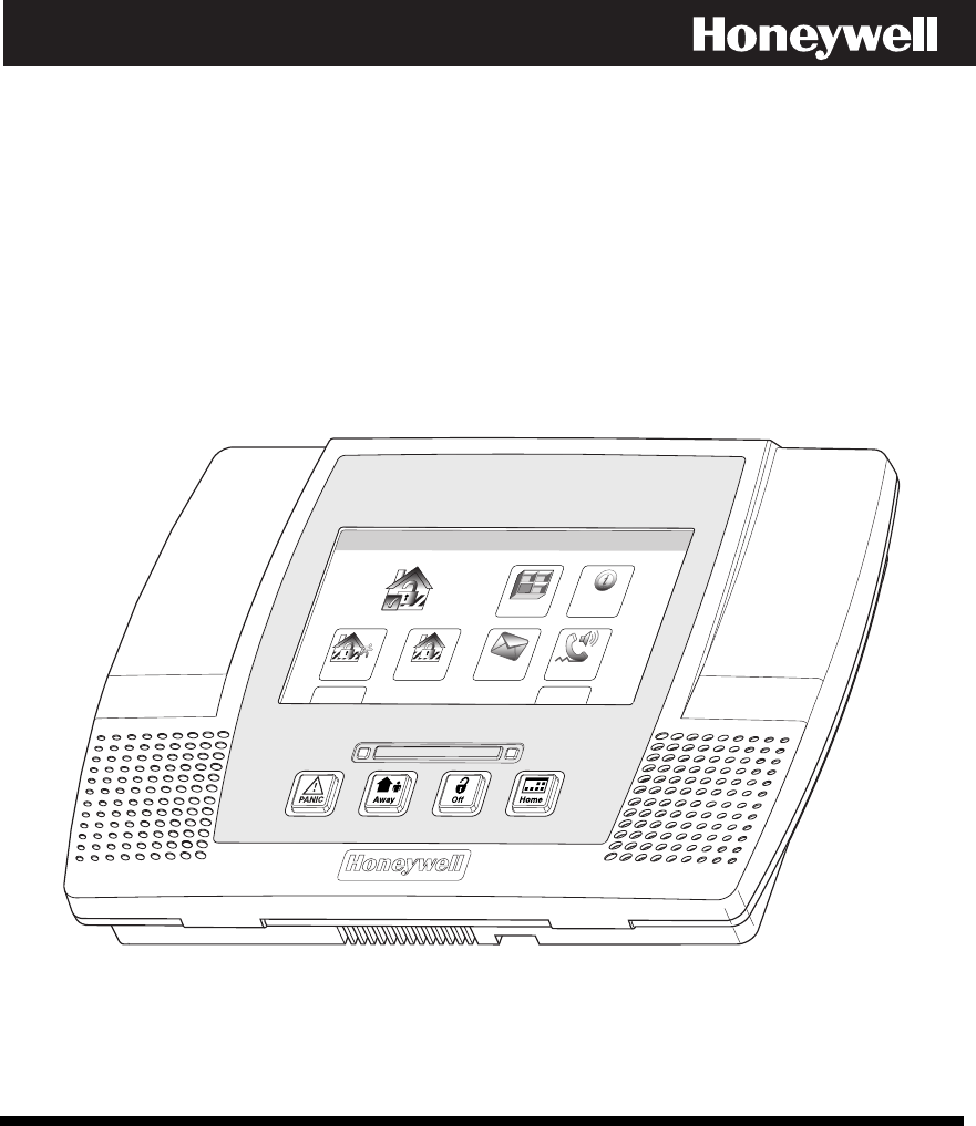
LYNX Touch
Security System
User Guide
ARMED READY
Zones
Arm Away
Ready To Arm
Arm Stay
MoreDelay
Phone
10:18 AM June 8, 2010
Message
System
800-06894 1/11 Rev. A
PLEASE USE THE BOOKMARKS
TO GO TO THE VARIOUS
AGENCY STATEMENTS

– 2 –
Your Honeywell security system is designed for use with devices manufactured or approved by
Honeywell for use with your security system. Your Honeywell security system is not designed for
use with any device that may be attached to your security system's control or other
communicating bus if Honeywell has not approved such device for use with your security system.
Use of any such unauthorized device may cause damage or compromise the performance of your
security system and affect the validity of your Honeywell limited warranty. When you purchase
devices that have been manufactured or approved by Honeywell, you acquire the assurance that
these devices have been thoroughly tested to ensure optimum performance when used with your
Honeywell security system.

– 3 –
TABLE OF CONTENTS
TABLE OF CONTENTSTABLE OF CONTENTS
TABLE OF CONTENTS
SYSTEM OVERVIEW..................................................................................................................................5
Features...................................................................................................................................................5
General Operation...................................................................................................................................6
Quick View of System Functions............................................................................................................9
About the Touchscreen Control ............................................................................................................10
Touchscreen Control Definitions ..........................................................................................................11
About the Display and Indicators.........................................................................................................13
Navigating Menus.................................................................................................................................15
SECURING THE PREMISES ..................................................................................................................17
System Status........................................................................................................................................17
Arming the System................................................................................................................................18
Entry/Exit Delays..................................................................................................................................23
Disarming the System...........................................................................................................................25
Bypassing Protection Zones..................................................................................................................27
Panic Keys .............................................................................................................................................29
Chime Mode...........................................................................................................................................31
Voice Mode.............................................................................................................................................32
USER FUNCTIONS ...................................................................................................................................33
User Access............................................................................................................................................33
View Events...........................................................................................................................................37
Message Recording and Playback.........................................................................................................39
System Adjustment ...............................................................................................................................41
Clock/Calendar ......................................................................................................................................42
Scheduling User Interface ....................................................................................................................45
Reminders..............................................................................................................................................48
Speaker Phone Feature.........................................................................................................................51
Remote Phone Control Feature ............................................................................................................53
Remote Services ....................................................................................................................................55
FIRE/CO ALARM SYSTEM......................................................................................................................56
General Information..............................................................................................................................56
National Fire Protection Association’s Smoke Detector Recommendations.......................................57
Emergency Evacuation .........................................................................................................................58
SYSTEM FUNCTIONS..............................................................................................................................59
Testing the System................................................................................................................................59
Maintaining Your System.....................................................................................................................61
Congratulations on your ownership of a Honeywell Security System. You have made a wise
decision in choosing it, for it represents the latest in security protection technology today.
Honeywell is the world's largest manufacturer of security system and millions of premises are
protected by Honeywell products.

– 4 –
TABLE OF CONTENTS
TABLE OF CONTENTSTABLE OF CONTENTS
TABLE OF CONTENTS
SUMMARY OF AUDIBLE & VISUAL NOTIFICATIONS ...................................................................63
System Displays ....................................................................................................................................64
Zone Status Icons ..................................................................................................................................64
FCC STATEMENTS ..................................................................................................................................66
OWNER’S INSURANCE PREMIUM CREDIT REQUEST..................................................................69
LIMITATIONS OF THIS ALARM SYSTEM..........................................................................................72
INDEX ..........................................................................................................................................................77
TWO YEAR WARRANTY..........................................................................................................................79

– 5 –
SYSTEM OVERVIEW
SYSTEM OVERVIEWSYSTEM OVERVIEW
SYSTEM OVERVIEW
Features
General Information
This system offers you three forms of protection: burglary, fire, and emergency, depending on
the configuration of your system. The system consists of a touchscreen control for system
operation, various wireless sensors that provide perimeter and interior burglary protection,
and optional smoke or combustion detectors to provide early fire warning. In addition,
optional wireless keypads may have been installed to allow you to control the system away
from the touchscreen control. The system may also be used as a speaker phone.
The system monitors protection zones and system status, displays appropriate information
on the touchscreen display, and initiates appropriate alarms. Your system may also have
been programmed to automatically send alarm or status messages over the phone lines or via
the cellular/GSM network or the internet to a central alarm monitoring station, and may also
be capable of two-way voice communication with the central station.
The user features of this security system are listed below. Ask your installer which
features have been programmed for your system.
• STAY and AWAY arming modes: By using these modes you can protect either the
perimeter only, or the entire premises.
• Panic key functions: A designated key allow you to manually activate fire, medical
emergency, or silent police alarms. Refer to the PANIC KEYS section for detailed
information.
• Follow me reminder announcements: Allows the panel to dial a number that you have
specified, at a programmed time and day and deliver a message programmed by your
installer.
• Real-time clock: Touchscreen displays current date and time. Refer to the
CLOCK/CALENDAR section for procedures for setting the time.
• Message center: The system allows recording and play back of brief messages. Refer to
the RECORDING/PLAYBACK MESSAGES section for procedures.
• Two-way voice: Allows the central station to listen, talk to or conduct two-way
conversations with individuals on the premises Refer to the TWO-WAY VOICE section for
detailed information.
• Phone Control: Provides a remote interactive phone capability that permits access to the
security system from any off-site touch-tone telephone. Refer to the Remote Phone Control
Feature section for detailed information.
• Speaker Phone Operation: The system is capable of operating as a speaker phone
allowing hands free telephone conversation.
• Security Codes: The system is capable of supporting an Installer code, Master user code
and 14 additional User codes including Babysitter and Duress codes. Refer to the
SECURITY CODES section for detailed information.

– 6 –
SYSTEM OVERVIEW
SYSTEM OVERVIEWSYSTEM OVERVIEW
SYSTEM OVERVIEW
General Operation
• Device activation: Allow you to turn lights and/or other devices on and off. In addition,
some devices (e.g., a light) may be programmed to activate automatically as a result of a
system event such as an alarm or trouble condition. Refer to the DEVICES section for
detailed information.
• Scheduling feature: Allows you to schedule the automatic activation or deactivation of
program events (e.g. alarm clock, reminder, and latch key). Refer to the SCHEDULES
section for detailed information.
Zones
Your system's sensing devices have been assigned to various "zones." For example, the
sensing device on your entry/exit door may have been assigned to zone 01, sensing devices on
windows in the master bedroom to zone 02, and so on. These numbers appear on the display
when an alarm or trouble condition occurs.
Fire Protection
The fire protection portion of your security system (if used) is always active and will sound
an alarm if a fire condition is detected. Refer to the FIRE ALARM SYSTEM section for
important information concerning fire protection, smoke detectors and planning emergency
exit routes from the premises.
Carbon Monoxide
The carbon monoxide (CO) portion of your security system (if used) is always active and will
sound an alarm if a CO condition is detected. Refer to the FIRE ALARM SYSTEM section for
more information.
Burglary Protection
Your system provides two modes of burglary protection: STAY and AWAY. STAY mode
protects the perimeter only, allowing you to freely move inside the premises. AWAY mode
protects the entire system. Both modes provide an entry delay time that allows you to
reenter the premises without setting off an alarm. For additional security, you can turn the
entry delay off when arming the system. Refer to the ARMING THE SYSTEM section. The
system also allows you to bypass selected zones before arming the system, if desired. Refer to
the BYPASSING PROTECTION ZONES section. The system also provides a CHIME mode,
for alerting users to the opening of protected doors and windows while the system is
disarmed.
You must arm the burglary protection portion of your system before it will sense burglary
alarms. Refer to the ARMING THE SYSTEM section for detailed procedures and
information.

– 7 –
SYSTEM OVERVIEW
SYSTEM OVERVIEWSYSTEM OVERVIEW
SYSTEM OVERVIEW
General Operation
LYNX Touch SIA False Alarm Prevention Features
Many false alarms are caused by simple accidents, like forgetting to close a door when you leave. The
LYNX Touch SIA includes several features that help prevent false alarms and some of these are
optional or programmable. Although turning off some of these features may provide additional security,
it may also increase the chance of false alarms. Your installer can help you decide whether to use the
features or not. The following provides a brief explanation of the features included with your security
system that help prevent false alarms from occurring, and what you should do if such alarms occur.
• Exit/Entry Delays: Your security system has been programmed with delay times that allow you to
exit the premises after arming, and to disarm the system upon entry, before an alarm occurs. If you
leave the premises too late when exiting, or disarm too late when arriving home, it will cause a false
alarm. If an alarm occurs, you should disarm the system immediately, and wait for your monitoring
company to call you.
• Exit Alarms: Leaving the premises and forgetting to close the door is a common cause of false
alarms. The security system will sound an alarm, and display “Exit Error”. The security system
provides extra time for you to disarm the system before dialing your monitoring company. Disarming
the system immediately may prevent a call to your monitoring company.
• Exit Time Restart-Exit Delay Restart/Reset: If you leave the premises and enter again before the
exit delay has expired, the system will restart the exit time giving you more time to leave. If there
are less than 10 seconds left to exit, the system will sound fast beeps, indicating an alarm will occur
soon if you fail to exit or disarm immediately. If this occurs, disarm the system and arm it again
when you are ready to leave. The Exit Delay can also be restarted by pressing the RESTART Icon.
• Auto Stay Feature: If you arm the system in the “AWAY” mode from the control’s keypad or an RF
keypad but no one exits, the alarm system will automatically change to the “STAY” mode. This will
prevent you from tripping alarms by remaining on premises. Disarm the system and arm away again
when you are ready to leave.
• Burglary Abort Window: Your security system has a delay between the time a burglary alarm
sounds, and the time the monitoring company is called. This delay gives you time to disarm the
security system before the alarm is reported to the monitoring company. This delay is factory preset
at 30 seconds, but may be increased or decreased by your installer.
• False Alarms: If a burglary or fire alarm condition occurs and the system has been disarmed, the
keypad will display “Alarm Cancelled”. If this was a false alarm, wait for the monitoring company to
call you. They will verify your security code or password and prevent them from calling emergency
personnel to respond to a false alarm.

– 8 –
SYSTEM OVERVIE
SYSTEM OVERVIESYSTEM OVERVIE
SYSTEM OVERVIEW
WW
W
General Operation
Security Codes
At the time of installation, you were asked to provide a personal 4-digit security or “Master
User” code. You must enter the user code when arming and disarming the system, and when
performing other system functions. As an additional security feature, other users who do not
need to know your code can be assigned up to 14 different security codes. Refer to the
SECURITY CODES section for procedures on adding security codes to the system.
Alarms
When an alarm occurs, the LYNX Touch internal sounder will sound for about 15-seconds,
and the touchscreen displays the zone(s) causing the alarm. After 15-seconds, the internal
sounder stops temporarily and voice announcements of the zones in alarm begins. When
these zones have been announced, the internal sounder sounds again and the cycle repeats
itself, until the system is disarmed or until alarm bell timeout occurs. If your system is
connected to a central monitoring station, an alarm message will be sent. To stop the alarm
sounding, simply disarm the system. The zone(s) causing the alarm remain displayed
indicating memory of alarm. Refer to the DISARMING THE SYSTEM section for
information about clearing the memory of alarm display
Two-Way Voice Feature
The control supports voice dialog between an operator at the central station and an
individual at the premises. This feature allows the central station to listen, talk to or conduct
a two-way conversation with an individual(s) at the premises and allows the operator to
gather information about the nature and location of the alarm that may be helpful in
responding to police or rescue departments. If the Two-way Voice Feature has been
programmed and an alarm condition is detected, the system sends an alarm message to the
central station. After acknowledgement is received, a “listen in to follow” message is sent to
the central station. In response to this message, the central station operator can enter
commands that allow him to initiate a 5-minute voice session.
If a subsequent zone is violated during a voice session, the system will terminate the session
and process the alarm. During the voice session, the ARMED (red) and READY (green) LEDs
will alternately blink in the Talk and VOX Modes but not during Listen Mode.

– 9 –
QUICK VIEW OF SYSTEM FUNCTIONS
QUICK VIEW OF SYSTEM FUNCTIONSQUICK VIEW OF SYSTEM FUNCTIONS
QUICK VIEW OF SYSTEM FUNCTIONS
SECURITY FUNCTIONS
Checking system status: ............................................. Select “System” icon.
To arm in STAY mode: ..............................................Select “Stay” icon then enter Code.
To restart exit delay: ................................................... Select “Restart Exit Delay” icon.
To arm in AWAY mode: ............................................. Select “Away” icon or depress “Away” key then enter
Code.
To arm INSTANT: ...................................................... Set “Delay” to ”Instant” . Select “Stay” or “Away” icon
or “Away” key then enter code.
To arm if Quick Arm* is active: .................................... Select “Stay” or “Away” icon or “Away” key followed
by Quick Arm tab on the touchscreen.
* User code is not required if Quick Arm is active.
To disarm system and silence alarms:......................... Depress “Off’” key or “Disarm” icon and enter Code
Note: During Entry Delay or when an Alarm Condition exists, the LYNX Touch can be disarmed by entering the User
Code. Entering the OFF key is not required
To bypass a zone(s): .................................................. Select “Zones” icon
To turn Chime mode on or off: .................................... Select “Settings” icon
MESSAGE CENTER
To record a message: ................................................. Select “Message” icon
VOLUME ADJUSTMENT
To adjust volume: ........................................................ Select “Settings” icon
To restore/unmute user announcements: .................... Select “Settings” icon
SPEAKER PHONE OPERATION
To enter speaker phone mode:.................................... Select “Phone” Icon
To enable/disable (toggle) ringer: ................................ Select “Settings” icon
OTHER FUNCTIONS (accessible to the Master User only)
To set the time and date: ............................................. Select “Date Time” icon (on Master User Menu)
To set scheduling:........................................................ Select “Schedules” icon (on Master User Menu)
To activate/deactivate devices:.................................... Select “Devices” icon (on Master User Menu)
To add/delete a user code* (except Master Code):...... Select “Users” icon (on Master User Menu)
* Only the master code can be used to add or delete another user code.
To turn Test mode On or Off:....................................... Select “Test” icon (on Master User Menu)
To view system events:................................................ Select “Events” icon (on Master User Menu)
To program or delete “Follow Me” Reminders: ............Select “Reminders” icon (on Master User Menu)
– 10 –
SYSTEM OVERVIEW
SYSTEM OVERVIEWSYSTEM OVERVIEW
SYSTEM OVERVIEW
About the Touchscreen Control
General
**IMPORTANT**
If the LYNX Touch is beeping rapidly upon entering the premises, an alarm has occurred
during your absence and an intruder may still be on the premises. LEAVE IMMEDIATELY
and CONTACT THE POLICE from a nearby safe location.
The touchscreen icons and keys allow you to control all system functions. Additionally, the
touchscreen display shows the zone and description of all system occurrences. When the
speaker phone mode is active, a full-function telephone keypad is displayed on the
touchscreen.
The system also features a built-in sounder, which will sound during alarms and troubles
and a built-in speaker announces system status. Additionally, the system "beeps" during
certain system functions, such as during entry/exit delay times, in Chime mode, and when
depressing any of the keys (to acknowledge the key press).
The voice announcement volume is adjustable, however the “beeps” that sound in response to
alarms always sound at the maximum volume level. All other “beeps” (trouble, chime,
exit/entry, etc) can be set to either low or high volume.
5000-100-002-V0
ARMED READY
– 11 –
SYSTEM OVERVIEW
SYSTEM OVERVIEWSYSTEM OVERVIEW
SYSTEM OVERVIEW
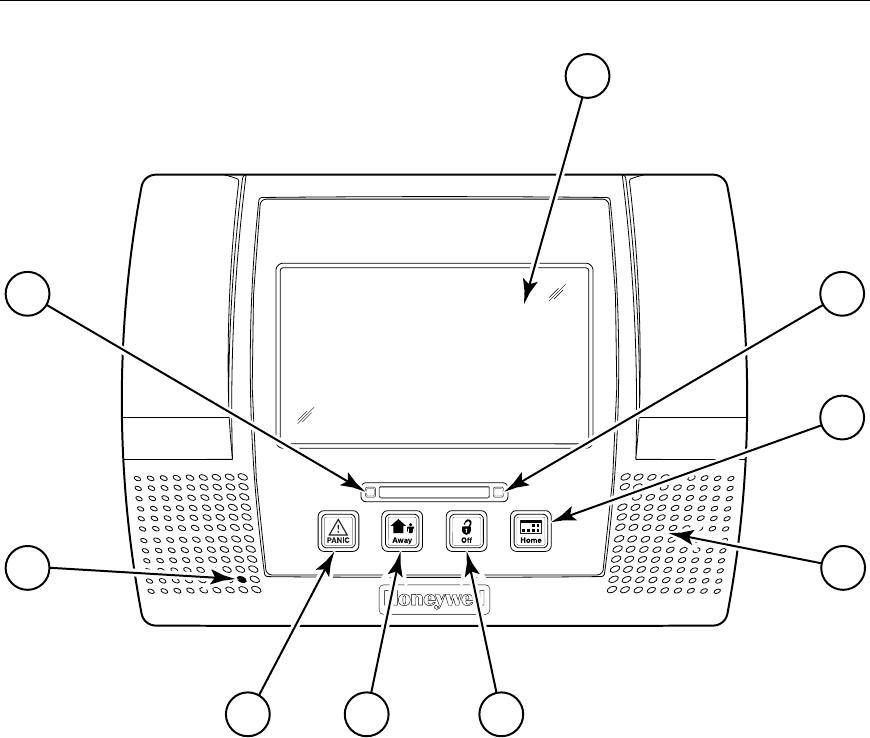
Touchscreen Control Definitions
5000-100-051-V0
ARMED READY
1
2
9
7 6 5
8 4
3
Note: The system functions described below are for reference only and require additional key entries to
activate.
1. DISPLAY WINDOW: Color Liquid Crystal Display (LCD). Displays system status icons, time,
system status information, user menus and the virtual keypad.
2. READY Indicator (LED): (GREEN) When lit, indicates system is ready to be armed; blinking
indicates system is not ready (a zone is open). Blinks once per second when AVM (VOX or Talk) or
speaker phone mode is active.
3. HOME Key: Used to exit from a screen or return to the home screen.
4. Speaker: Source of audible internal warning and confirmation sounds, status announce-
ments, as well as alarms (see "Summary of Audible Notifications").

– 12 –
SYSTEM OV
SYSTEM OVSYSTEM OV
SYSTEM OVERVIEW
ERVIEWERVIEW
ERVIEW
Touchscreen Controls Definitions
5. OFF (Disarm) KEY: Initiates the disarm process and causes a keypad to be displayed on
the touchscreen. Disarms the burglary portion of the system, silences alarms and audible
trouble indicators, and clears alarm trouble display after the problem has been corrected.
6. AWAY KEY: Completely arms both perimeter and interior burglary protection for backup
protection by sensing an intruder's movements through protected interior areas as well as
guarding protected doors, windows, etc. Entrance can be made through an entry delay
zone without causing an alarm if the system is disarmed before the entry delay time
expires.
7. PANIC Key: When depressed for 4 seconds, the virtual panic icons are displayed on the
touchscreen.
8. MICROPHONE: Used to record personal messages via the Message Center, and for two-
way voice and speaker phone operation.
9. ARMED Indicator (LED): (RED) Lit when the system has been armed (STAY, AWAY).
Blinks when armed and fault exists, or once per second when AVM (VOX or Talk) or
speaker phone mode is active.
LED Meanings
ARMED LED: ON = System armed
(Red) OFF = System disarmed
Blinking = System armed, and an alarm is in progress or was previously.
Blinking alternately with READY LED = speaker phone mode is active
READY LED: ON = System disarmed, ready to arm
(Green) OFF = System armed
Blinking = System disarmed, not ready to arm (a fault exists)
Blinking alternately with ARMED LED = speaker phone mode is active.
– 13 –
SYSTEM OVERVIEW
SYSTEM OVERVIEWSYSTEM OVERVIEW
SYSTEM OVERVIEW
About the Display and Indicators
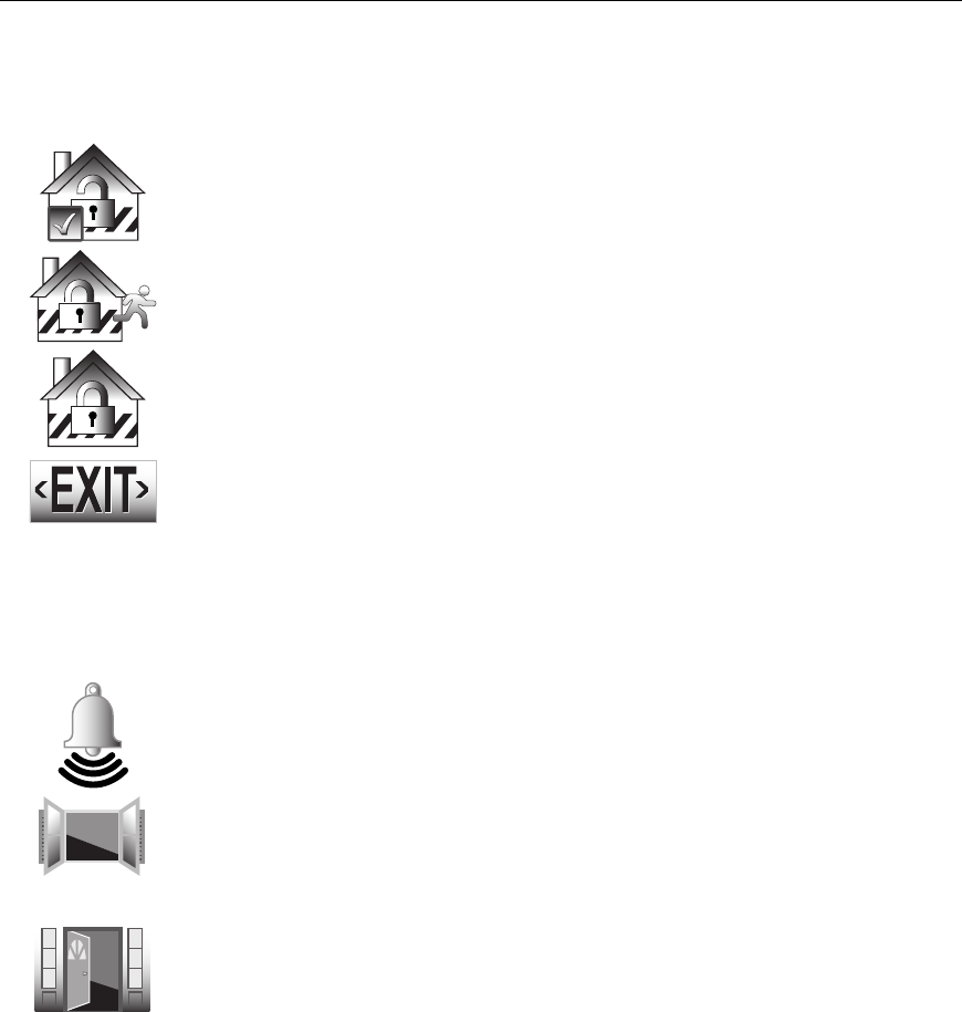
Display Definitions
ICON TEXT
DEFINITION
Ready to
Arm
Displayed along with the the text “READY TO ARM” when
system is Disarmed and ready to arm.
Armed:
Away
“Armed: Away” is displayed along the top of the screen. An
armed away icon along with “Armed: Away” is displayed after
the exit delay expires.
Armed: Stay “Armed: Stay” is displayed along the top of the screen. An
armed stay icon along with “Armed: Stay” is displayed after
the exit delay expires.
Exit Now
28 Seconds
“Armed: Stay – Exit Now” or “Armed: Away – Exit Now” is
displayed in a red band along the top of the screen. An exit
icon along with “Exit Now” and the time remaining (i.e.; “28
Seconds”) is displayed during the exit delay.
when the system is armed in the Stay mode. The text “Armed:
Stay Exit Now” Once the exit delay expires “Armed: Stay” is
displayed along with the Home Screen.
Note: Display alternates with ARMED STAY icon and text
Alarm “Alarm” is displayed in a red band along the top of the screen.
An alarm (bell) icon along with “Alarm” is displayed alternately
with the Zone that has caused the alarm.
OR
Fault (Zone
No.&
Description)
“Not Ready To Arm – Fault” is displayed in a yellow band
along the top of the screen. An open windowor door icon
along with the zone descriptor and “Window” or “Door” is
displayed when a window or entry/exit fault has been
detected.
OR
Displayed alternately with the alarm (bell) icon and “Alarm”.
“Alarm” is also displayed in a red band along the top of the
screen.
– 14 –
SYSTEM OVERVIEW
SYSTEM OVERVIEWSYSTEM OVERVIEW
SYSTEM OVERVIEW
About the Display and Indicators
ICON TEXT
DEFINITION
Fire OR
Fire Alarm
95 Fire
The fire icon is displayed with alternating text “Fire” and “Fire
Alarm 95 Fire”. “Fire Alarm” is also displayed in a red band
along the top of the screen.
Alarm 96
Medical
The Medical icon isplayed when a medical alarm is activated.
“Alarm” is also displayed in a red band along the top of the
screen.
(If programmed for display by your installer)
Alarm 99
Police
The alarm (bell) icon when a burglary alarm is activated.
“Alarm” is also displayed in a red band along the top of the
screen.
(If programmed for display by your installer)
CO Alarm Displayed alternately with the alarm (bell) icon when a CO
alarm is activated.
“Alarm” is also displayed in a red band along the top of the
screen.
Cover
Tamper
A check system icon along with “Cover Tamper” is displayed
when a cover tamper has been detected. “Ready To Arm –
System Trouble” is displayed in a yellow band along the top of
the screen.
Reporter
Failure
The system has identified a problem with the telephone dialer.
Low
Battery
“Not Ready To Arm – System Trouble” is displayed in a yellow
band along the top of the screen. A low battery icon along with
“Low Battery” is displayed when the system’s backup battery
power is low.
90 RF Jam Appears when the system has detected an RF jamming
condition or excessive interference.
94 Phone
Line Cut
Appears when the system has detected a loss of telephone
service.
AC Loss Displayed when the system has lost AC power. “Ready To
Arm – System Trouble” is displayed in a yellow band along the
top of the screen.
– 15 –
SYSTEM OVERVIEW
SYSTEM OVERVIEWSYSTEM OVERVIEW
SYSTEM OVERVIEW
Navigating Menus
LCD Display
LYNX Touch’s Liquid Crystal Display (LCD) touch-screen displays variable icons and text on
“screens”. The screen displays status icons and associated text, the current time, system
status information and menu choices. The system status is displayed in a colored band along
the top of the screen. The band color is variable and will change between red, yellow and
green as the system status changes.
The Menu area includes a list of commands, or choices that apply to the current selection.
The status area provides information about various system events. A “Home Screen” is
displayed whenever power is applied to the system. In addition the green ‘READY” LED will
be lit.
Zones
Arm Away
Ready To Arm
SYSTEM
STATUS
SYSTEM/ZONE
STATUS
Arm Stay
MoreDelay
Phone
10:18 AM June 8, 2010
5000-100-054-V0
Message
System
LYNX Touch Home Screen (page 1)
Navigation Keys
Navigating through the screens is accomplished by lightly touching the menu item on the
touch-screen. Once activated, the control will take you to the next screen. Selecting the
“Home” (cancel) key or the “2” Key will return you to the home screen at any time unless
System Programming mode is active.
Note: You may find it convenient to adjust the volume setting before entering the Program (Tools) Mode.
This will allow you to clearly hear the feedback announcements or system beeps in the Programming
Mode, of the system’s built-in speaker. To adjust the volume, select “More” on the “home Screen” and
then select “Settings”. Adjust the volume using the slide shown on the Settings screen and then
select “Save” to accept.

– 16 –
SYSTEM OVERVIEW
SYSTEM OVERVIEWSYSTEM OVERVIEW
SYSTEM OVERVIEW
Navigating Menus
Menu Screens
System Status is displayed at the top of each screen. The time and date are displayed at the
bottom of the Home Screen.
Menus
Unrestricted Menu
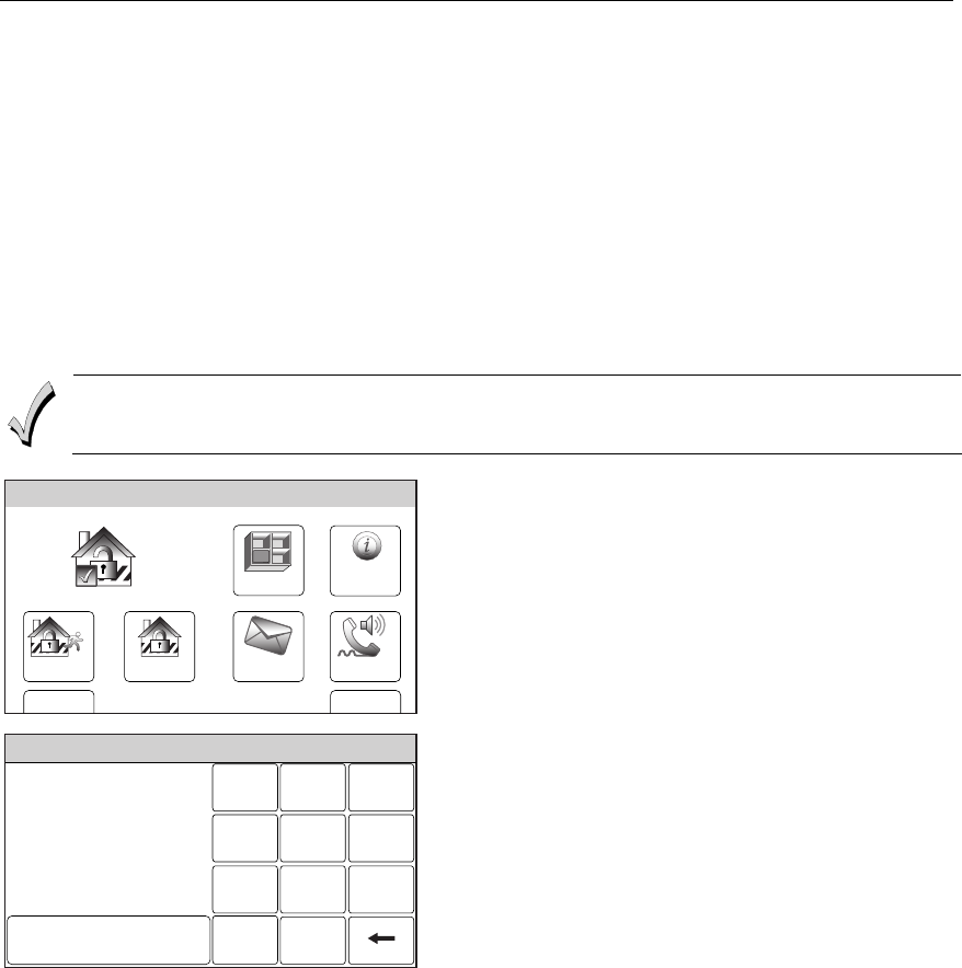
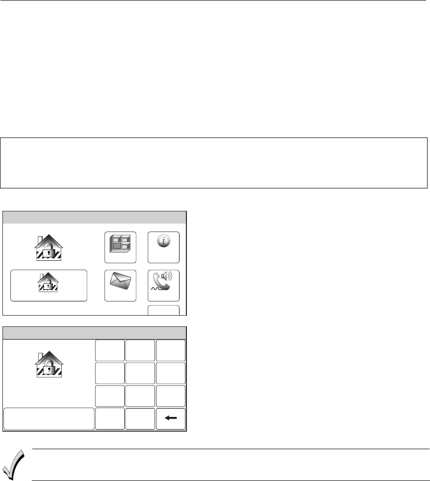
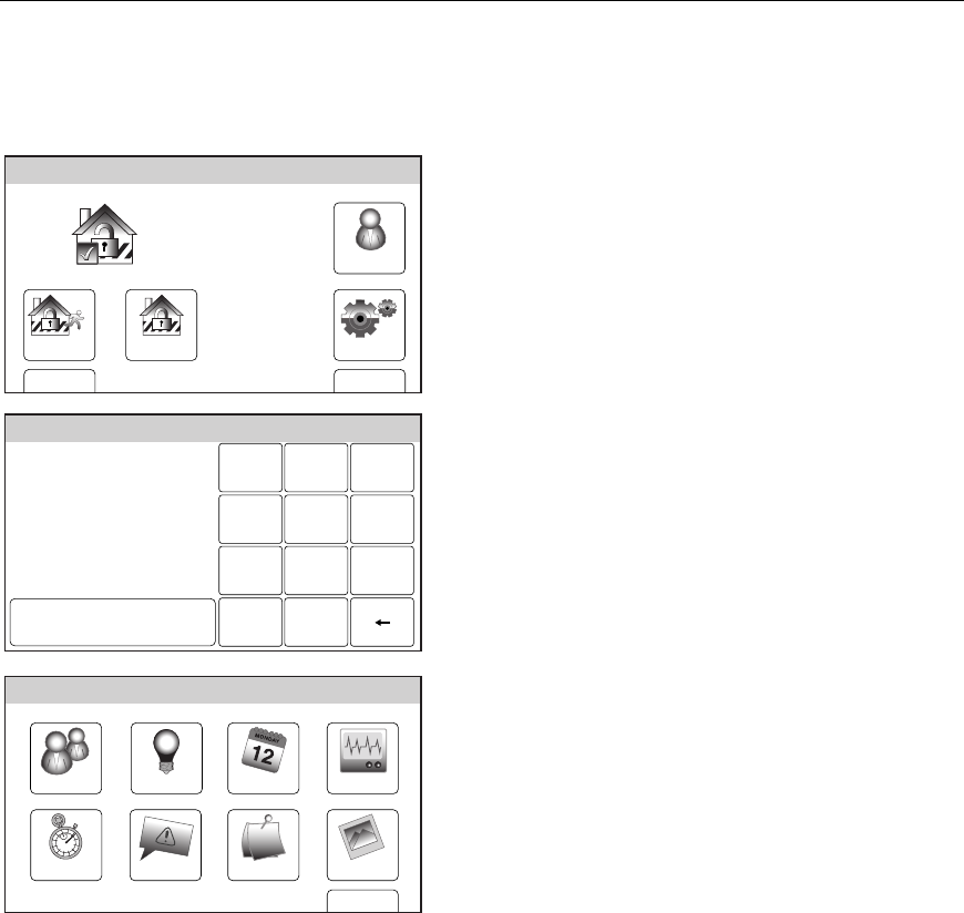
The first page of the Home Screen provides access to an Unrestricted Menu displays the
system status and eight selection icons or “buttons”.
1. Zones – Provides access to Zone information and options.
2. System – Provides information about system status.
3. Arm Away – Used to Arm the system in Away mode.
4. Arm Stay – Used to Arm the system in Stay mode.
5. Message – Provides access to Message Center.
6. Phone – Provides access to Speaker Phone mode (if programmed).
7. Delay/Instant – Used to toggle between exit delay and instant arming options.
8. More – Advances system to second page of the Home Screen.
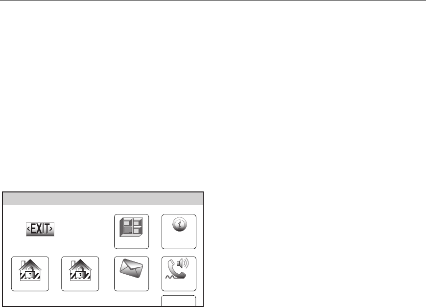
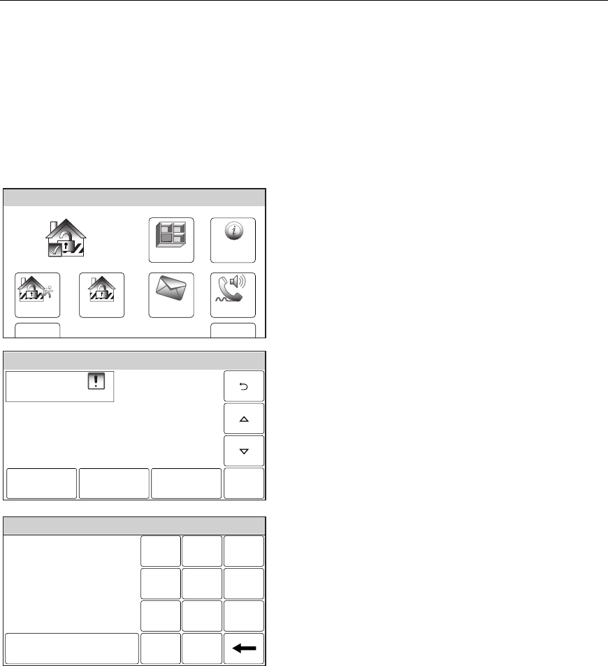
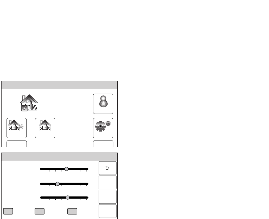
The second page of the Home Screen displays the system status in and seven options.
1. Tools – Provides access User Programming Menus (Master User Code required for
access).
2. Arm Away – Used to Arm the system in Away mode.
3. Arm Stay – Used to Arm the system in Stay mode.
4. Settings – Provides access to various touchscreen functions including Brightness,
Contrast, Volume, Voice, Chime and Ringer.
5. Delay/Instant – Used to toggle between exit delay and instant arming options.
6. Back – Returns system to first page of the Home Screen.
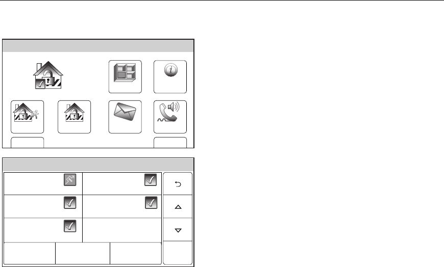
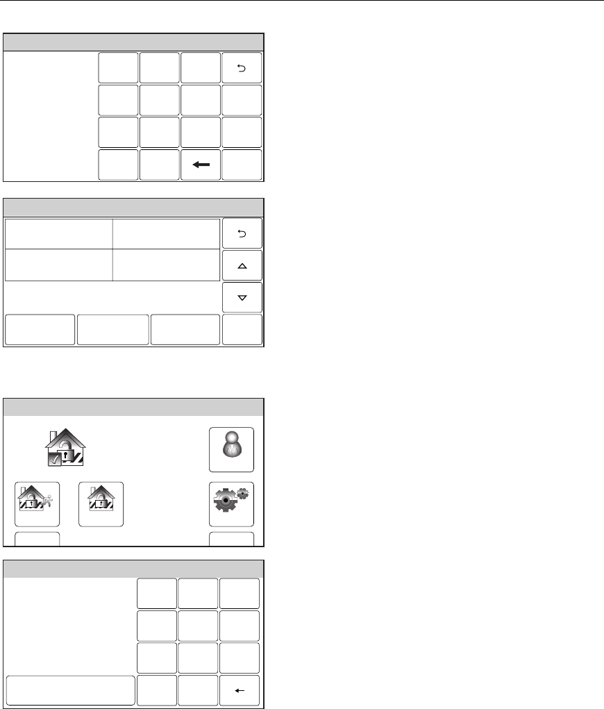
Master Menu
The User Menu provides access to User configurable features and displays eight options.
Entering the Master User Code is required to access the Master menu.
1. Users – Allows Master User to add or remove User Codes
2. Devices – Allows Master User to program output triggers.
3. Schedules – Allows Master User to program schedules
4. Test – Allows Master User to Test the system
5. Date Time – Used to program date and time.
6. Events – Allows Master User to view system events
7. Reminders – Allows Master User to add or remove local and “Follow Me” reminders.
8. Slide Show – Allows Master User to select a slide show for use as a screensaver.
9. Back – Returns system to first page of the Home Screen.

– 17 –
SECURING THE PREMISES
SECURING THE PREMISESSECURING THE PREMISES
SECURING THE PREMISES
System Status
General Information
Before arming your system, all protected doors, windows, and other protection zones must be
closed or bypassed (see the BYPASSING PROTECTION section).
READY LED: The green READY indicator on the control will be lit if the system is ready to
be armed. If blinking, the system is not ready.
NOTE: The phrases shown in brackets are variable, and are announced only if appropriate in the
current state of the system.
Depending on the current state of the system the following phrases may be heard:
fire alarm [zone voice descriptors]
carbon monoxide alarm [zone voice descriptors]
alarm [zone voice descriptors]
fire fault [zone voice descriptors]
carbon monoxide fault [zone voice descriptors]
fault [zone voice descriptors]
low battery [zone voice descriptor]
system low battery
check system
AC loss
zones bypassed
chime
VOLUME LEVEL: The volume level of system announcements can be increased or decreased. Refer to
the MESSAGE RECORDING/PLAYBACK section for the procedure.
System Can Be Armed
The READY LED will be lit steadily once all protection zones have been closed or bypassed.
You may now arm the system.
– 18 –
SECURING THE PREMISES
SECURING THE PREMISESSECURING THE PREMISES
SECURING THE PREMISES
Arming the System
Arming in Stay Mode
Use this mode when you are staying home, but expect someone to use the entrance door
later. Close all protected perimeter windows and doors before arming. The green READY
indicator on the control should be lit if the system is ready to be armed. When armed in
STAY mode, the system will sound an alarm if a protected door or window is opened, but you
may otherwise move freely throughout the premises. Late arrivals can enter through the
designated entrance door without causing an alarm, but they must disarm the system within
the entry delay period or an alarm will occur. If Quick Arm was programmed by the installer,
you do not need to enter the security code to arm the system. The security code must always
be used to disarm the system, however.
The Babysitter Code and Installer Code cannot disarm the system unless it was used to arm
the system. In addition, if the system is armed by pressing via Quick-Arming, neither the
Babysitter Code nor Installer Code can disarm the system.
Zones
Arm Away
Ready To Arm
Arm Stay
MoreDelay
Phone
10:18 AM June 8, 2010
5000-100-006-V0
Message
System
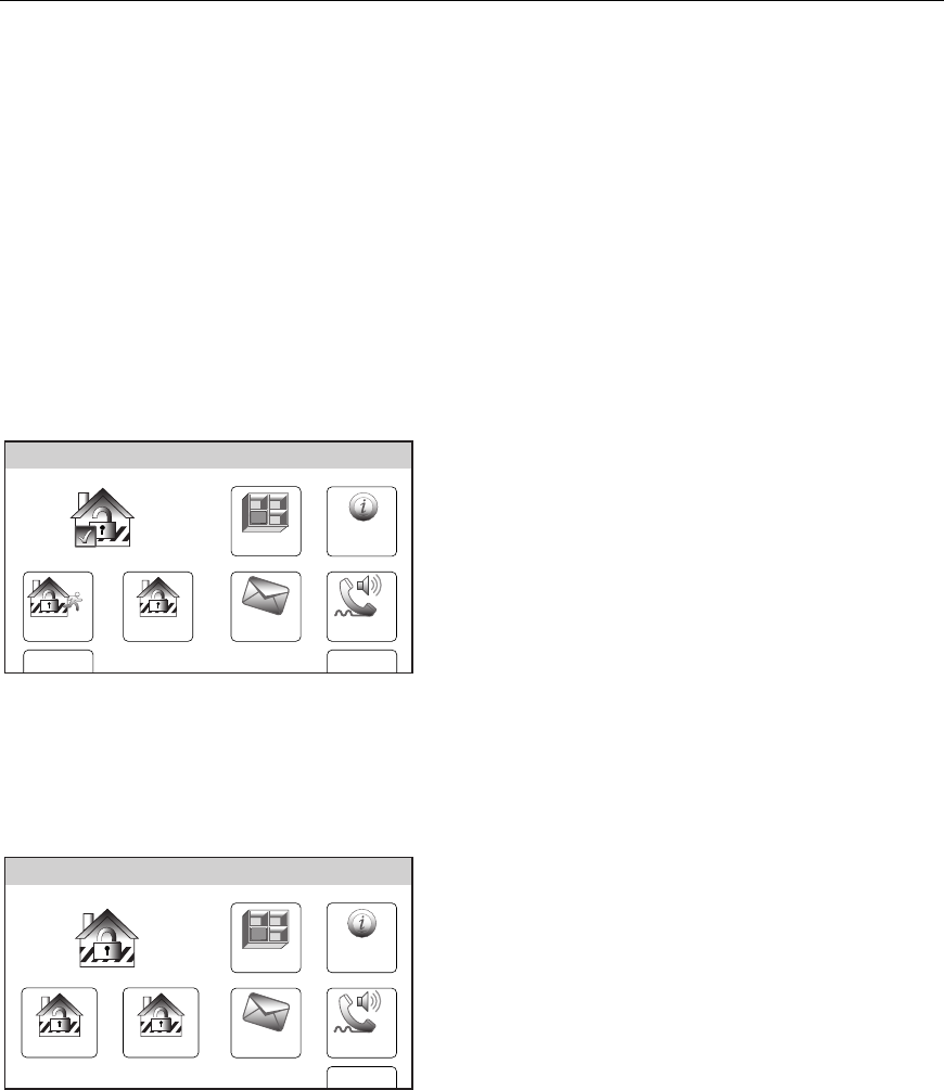
1. Select the Arm Stay icon, the system will
beep once and display a keypad.
Ready To Arm
Arm the system in Stay mode
Enter Code:
Cancel
231
564
0
897
Clear
5000-100-137-V0
2. Enter a valid User Code.
OR
If Quick Arm has been enabled, select the
“Quick Arm” icon.
The system will beep three times and
announce “Armed Stay Exit Now”. The exit
delay screen will be displayed. If
programmed the display will count down
the time remaining in the exit delay.
Note: If a valid user code is not entered or the
Confirm icon has not been selected within
10 seconds, the system will return to the
“home” screen and it will not be armed.
– 19 –
SECURING THE PREMISES
SECURING THE PREMISESSECURING THE PREMISES
SECURING THE PREMISES
Arming the System
Armed: Stay
More
10:18 AM June 8, 2010
5000-100-056-V0
Zones
Message
System
Disarm Phone
3. At the end of the exit delay the system
will announce “Armed Stay” and
display the “Armed Stay” screen.
If an invalid User Code is entered, the system will return to the home screen.
Auto Stay Feature
If this feature is enabled by installer, the LYNX Touch SIA, when armed AWAY from the control’s
keypad or a Wireless Keypad, switches to the STAY mode if the Exit Time expires and no exit has been
made.
NOTE: If the exit route entry/exit sensor is in a check condition or has been bypassed it will result in a loss of interior
protection because the alarm system will arm STAY in this case. Consult with your installer for servicing of the
entry exit zones or to turn off this feature if a check condition on entry exit zones occurs.
– 20 –
SECURING THE PREMISES
SECURING THE PREMISESSECURING THE PREMISES
SECURING THE PREMISES
Arming the System
Arming In Away Mode
Use this mode when no one will be staying on the premises. Close all protected perimeter
windows and doors before arming. The green READY indicator on the control should be lit if
the system is ready to be armed. When armed in AWAY mode, the system will sound an
alarm if a protected door or window is opened, or if any movement is detected inside the
premises, when infrared detection devices are used. You may leave through a designated
entrance door during the exit delay period without causing an alarm. You may also re-enter
through the entrance door, but you must disarm the system within the entry delay period or
an alarm will occur. If Quick Arm was programmed by the installer, you do not need to enter
the security code to arm the system. The security code must always be used to disarm the
system, however.
The Babysitter Code and Installer Code cannot disarm the system unless it was used to arm
the system. In addition, if the system is armed by pressing via Quick-Arming, neither the
Babysitter Code nor Installer Code can disarm the system.
Zones
Arm Away
Ready To Arm
Arm Stay
MoreDelay
Phone
10:18 AM June 8, 2010
5000-100-006-V0
Message
System
1. Select the Arm Away icon, the system will
beep once and display a keypad.
Ready To Arm
Arm the system in Away mode
Enter Code:
Cancel
231
564
0
897
Clear
5000-100-053-V0
2. Enter a valid User Code.
OR
If Quick Arm has been enabled, select the
“Quick Arm” icon.
The system will beep two times and announce
“Armed Away Exit Now. The exit delay screen
will be displayed. If programmed the display
will count down the time remaining in the exit
delay in seconds.
Note: If a valid user code is not entered or the Confirm
icon has not been selected within 10 seconds,
the system will return to the “home” screen and it
will not be armed.
– 21 –
SECURING THE PREMISES
SECURING THE PREMISESSECURING THE PREMISES
SECURING THE PREMISES
Arming the System
Armed: Away
More
10:18 AM June 8, 2010
5000-100-057-V0
Zones
Message
System
Disarm Phone
3. If “Exit Warning” has been enabled, the
system will continue to beep throughout
the exit delay. Rapid beeps will sound for
the final 10 seconds of the delay period. At
the end of the exit delay the system will
announce “Armed Away” and displays the
“Armed Away” screen.
If an invalid User Code is entered, the system will return to the home screen and will
alternate with a keypad screen.
– 22 –
SECURING THE PREMISES
SECURING THE PREMISESSECURING THE PREMISES
SECURING THE PREMISES
Arming the System
Arming the System with no delay (Instant)
Use “Instant” with Stay mode when you are staying home and do not expect anyone to use
the entrance door.
Use “Instant” with Away mode when the premises will be vacant for extended periods of time
such as vacations, etc.
When armed with “Instant”, the control beeps twice, or beeps continuously if exit warning
has been programmed for your system, and displays the “Armed Stay Instant” or “Armed
Away Instant” message. The red ARMED indicator lights and the system announces “Armed
Stay Instant –exit now” or “Armed Away Instant –exit now”.
When armed with “Instant”, the system will sound an alarm if a protected door or window is
opened, including the entrance door. You may leave through the entrance door during the
exit delay period without causing an alarm, but an alarm will sound as soon as someone
reenters.
To arm the system with no delay (Instant)
Zones
Arm Away
Ready To Arm
Arm Stay
MoreDelay
Phone
10:18 AM June 8, 2010
5000-100-006-V0
Message
System
1. Select the “Delay” tab on the home screen.
The icon will ‘toggle” and “Instant” will be
displayed.
2. Arm the system in the “Stay” or Away” mode
normally.
Note: The entry delay time is eliminated when
“Instant” is selected.
Quick Exit
If active, you can restart the exit delay at any time after arming has been armed in Stay or
Away mode by selecting the “Quick Exit” icon. This avoids having the user disarm then re-
arm the system after allowing someone to enter or exit. The system will re-arm once the exit
delay expires.
Armed: Stay
More
10:18 AM June 8, 2010
5000-100-060-V0
Zones
Message
System
Phone
Disarm Quick Exit
1. Select the “Quick Exit” icon to restart the exit
delay.
Note: Quick Exit is active in Away mode when : Auto
Stay mode is enabled and no entry/exit zone
has been faulted during the exit delay period.
– 23 –
SECURING THE
SECURING THESECURING THE
SECURING THE PREMISES
PREMISES PREMISES
PREMISES
Entry/Exit Delays
Entry/Exit DelaysEntry/Exit Delays
Entry/Exit Delays
Exit Delay
Exit delay begins immediately after arming the system, and gives you time to leave through
the designated exit door without setting off an alarm. The system display will count down
the time remaining in the exit delay, if programmed by your installer. If the system has been
Armed Away, a slow beeping will sound throughout the exit delay period, if programmed by
your installer. The exit door must be closed before the end of the exit delay. During the last
10 seconds of the exit delay fast beeps will sound as a warning that the delay time is nearing
its end. The exit beeps cannot be silenced.
Restarting Exit Delay While System Armed
Ask your installer if this feature is active for your system. If active, you can restart the exit
delay one time after arming in Stay or Away mode during the exit delay by selecting the
“Restart” key. This will allowing extra time for someone to enter or exit or re-enter the
property before the system is armed.
Disarm
Armed: Stay - Exit Now
Exit now
28 seconds
More
10:18 AM June 8, 2010
5000-100-061-V0
Restart
Zones
Phone
Message
System
Exit Alarms
To minimize false alarms sent to the alarm monitoring company, your system may have been
programmed for this feature. Ask your installer if Exit Alarm is active for your system.
Whenever you arm the system, the exit delay begins. If an entry/exit door or interior zone is
faulted when the exit delay ends (e.g., exit door left open), the system sounds an alarm and
starts the entry delay timer. If you disarm the system before the entry delay ends, the alarm
sound stops and the message “Alarm Cancelled is displayed, in the system bar. Additionally,
Alarm and the faulted zone are displayed with their associated icons in the system/zone
status area. No message is sent to the alarm monitoring company. To clear the exit alarm
condition, the open zone must be secured. To clear the display, select the “Disarm” icon OR
depress the “Off” key and then enter your security code.
If you do not disarm the system before the entry delay ends, and an entry/exit door or
interior zone is still open, the alarm sound continues and an "exit alarm" message is sent to
the alarm monitoring company. The message “Alarm Exit Error" is displayed, in the system
bar. Additionally, Alarm and the faulted zone are displayed with their associated icons in the

– 24 –
SECURING THE PREMISES
SECURING THE PREMISESSECURING THE PREMISES
SECURING THE PREMISES
Entry/Exit Delays
Entry/Exit DelaysEntry/Exit Delays
Entry/Exit Delays
system/zone status area. The alarm will continue to sound until the system is disarmed or
timeout ocurs. To stop the alarm, the system must be disarmed by selecting the “Disarm”
icon OR depressing the “Off” key and then entering your security code. The message “Alarm
Cancelled" is displayed, in the system bar, indicating that the alarm has been cancelled (if
this feature is enabled by the installer). “Alarm” and the faulted zone continue to be
displayed with their associated icons in the system/zone status area. To clear the display,
select the “Disarm” icon OR depress the “Off” key and then enter your security code a second
time. An exit alarm also results if an entry/exit door or interior zone is faulted within two
minutes after the end of the exit delay.
Entry Delay
Entry Delays give you time to disarm the system when you re-enter through the designated
entrance door. You must disarm the system before the entry delay period ends, or an alarm
will occur. The control beeps during the entry delay period, reminding you to disarm the
system. There are two entry delays (if programmed). The first is for your primary entrance
and the second can be used for a secondary entrance, where a longer delay is required to
walk to the control to disarm the system. You can also arm the system with no entry delay at
all by selecting the “Delay” icon prior to arming the system. This will toggle the system to
“Instant”, which can provide greater security while on the premises or while away for
extended periods of time. See ARMING THE SYSTEM section for procedure. See your
installer for delay times programmed for your system.
Exit Delay: None, 30, 45, 60, 90 seconds, 2 minutes
Entry Delay 1: None, 30, 45, 60, 90 seconds, 2 minutes
Entry Delay 2: None, 30, 45, 60, 90 seconds, 2 minutes
LYNX Touch SIA Exit/Entry Delay Times
Exit Delay: 45, 60, 90 seconds, 2 minutes
Entry Delay 1: 30, 45, 60, 90 seconds, 2, 3, 4 minutes
Entry Delay 2: 30, 45, 60, 90 seconds, 2, 3, 4 minutes
– 25 –
SECURING THE PREMISES
SECURING THE PREMISESSECURING THE PREMISES
SECURING THE PREMISES
Disarming the System
Select the “Disarm” icon or the “Off” key to disarm the system and to silence alarm and
trouble sounds. See the SUMMARY OF AUDIBLE NOTIFICATION section for information,
which will help you to distinguish between fire and burglary alarm sounds. During Entry
Delay or when an Alarm Condition exists, the system will be disarmed as soon as the correct
user code is entered on the touchscreen. Selecting the OFF key is not required. The entry
beeps or alarm sound can be silenced by pressing any key however, it will restart in 10
seconds if the correct User Code is not entered. The READY indicator will light (if no alarms
have occurred while armed) and the control will beep once to confirm that the system is
disarmed.
**IMPORTANT**
If the LYNX Touch is beeping rapidly upon entering the premises, an alarm has occurred
during your absence and an intruder may still be on the premises. LEAVE IMMEDIATELY
and CONTACT THE POLICE from a nearby safe location.
Disarming the system and silencing alarms
Armed: Stay
More
10:18 AM June 8, 2010
5000-100-056-V0
Zones
Message
System
Disarm Phone
1. Select the “Disarm” icon or depress the
“Off” key. The system will beep once and
display a keypad.
Armed Stay
Enter Code:
Cancel
231
564
0
897
Clear
5000-100-065-V0
2. Enter a valid Code. The system will beep
once and announce “Disarmed Ready to
Arm”.
Note: If a valid user code is not entered or the
Confirm icon has not been selected
within 30 seconds, the system will return
to the “home” screen and it will not be
disarmed.
If an invalid User Code is entered, system will return to the home screen.

– 26 –
SECURING THE P
SECURING THE PSECURING THE P
SECURING THE PREMISES
REMISESREMISES
REMISES
Disarming the System
When an Alarm Occurs
When an alarm has occurred, the touchscreen displays the zone number(s) that caused the
alarm and the type of alarm (e.g., “Fire Alarm”). These messages remain displayed until
cleared by a user. To clear the display, note the zone number displayed and enter an Off
sequence. If the fault cannot be corrected, notify your alarm company.
– 27 –
SECURING THE PREMISES
SECURING THE PREMISESSECURING THE PREMISES
SECURING THE PREMISES
Bypassing Protection Zones
Bypassing Individual Zones
The Bypass feature can be used when you want to intentionally arm your system with one or
more zones unprotected. Bypassed zones are unprotected and will not cause an alarm when
violated while your system is armed. All bypasses are removed when an Off sequence
is performed. Bypasses are also removed if the arming procedure that follows the bypass
command is not successful. The system will not allow panic, fire or CO zones to be
bypassed.
Bypassing zones
Zones
Arm Away
Ready To Arm
Arm Stay
MoreDelay
Phone
10:18 AM June 8, 2010
5000-100-006-V0
Message
System
1. With the system in the disarmed state,
select the “Zones” icon. The system displays
the Zones/Bypass screen.
Not Ready To Arm - Fault
5000-100-141-V0
2. Front
Door
Select
Fault
FAULT
Bypass All
Faulted Bypass
Clear
Bypasses
2. Select the zone(s) that you wish to bypass
and then select “Bypass” OR if programmed,
the “Bypass All Faulted” button allows you to
bypass all faulted zones (excluding Panic,
Fire or CO zones). The system displays a
keypad.
Not Ready to Arm - Fault
Bypass Selected Zones
Enter Code:
Cancel
5000-100-067-V0
231
564
0
897
Clear
3. Enter a valid Code. The system returns to
the Bypass screen and the zone(s) that are
bypassed will be displayed.
4. Select the 2 icon to return to the home
screen.
5. Arm the system normally. See ARMING
THE SYSTEM section for procedure
– 28 –
SECURING THE PREMISES
SECURING THE PREMISESSECURING THE PREMISES
SECURING THE PREMISES
Bypassing Protection Zones
Displaying Bypassed Zones
Zones
Arm Away
Ready To Arm
Arm Stay
MoreDelay
Phone
10:18 AM June 8, 2010
5000-100-006-V0
Message
System
Ready To Arm
5000-100-066-V0
99. Police
95. Fire 96. Medical
2. Front
Door
Select
All
READY
BYPASSED
READY
READY
3. Garage
Door
READY
Bypass All
Faulted Bypass
Clear
Bypasses
1. With the system in the disarmed state,
select the “Zones” icon. The system displays
the Zone screen and the status for each
zone will be indicated.
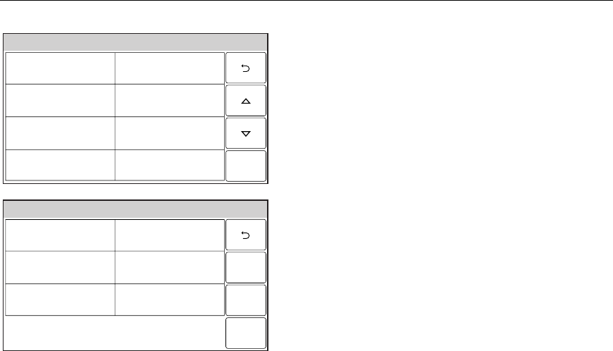
2. Use the “S” “T” buttons to scroll to
additional pages and view the zone status.
3. If you select the “Select All” button it
functions scrolls through the following:
“Select All”, “Select Alarm”, “Select Trouble”
and “Select Fault”. The system will display
the associated zones.
– 29 –
SECURING THE PREMISES
SECURING THE PREMISESSECURING THE PREMISES
SECURING THE PREMISES
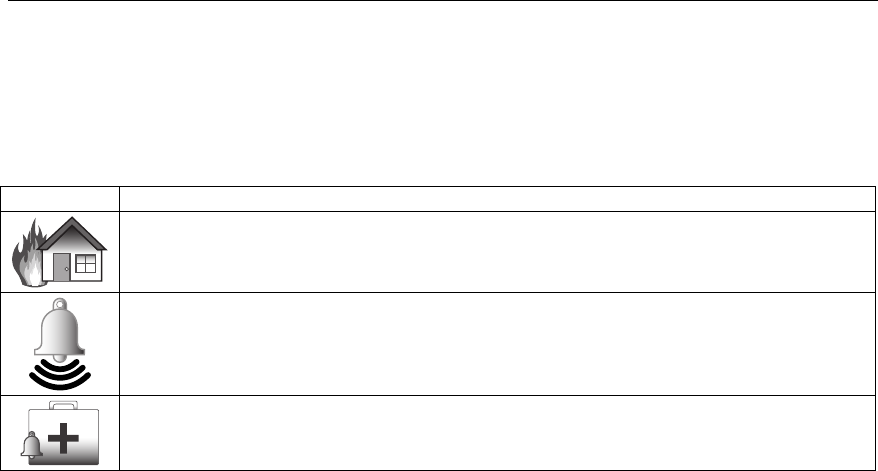
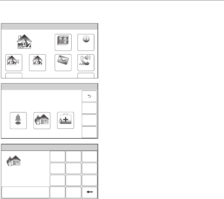
Panic Keys
Panic Keys
Your system may have been programmed to use special keys to manually activate panic
functions. The functions that might be programmed are listed below. See your installer for
the function(s) that may have been programmed for your system.
Note: Your installer should advise which functions are active in your system.
Key Function
When activated, alerts the alarm monitoring company that a fire condition exists.
When activated, alerts the alarm monitoring company that a police emergency
exists.
When activated, alerts the alarm monitoring company that a health emergency
exists.
Types of Panic Alarms
• A silent emergency/silent alarm sends an alarm signal to the alarm monitoring
company, if your system is connected to an alarm monitoring company, but there will be
no audible alarms or visual displays.
• An audible emergency/audible alarm sends an emergency message to the alarm
monitoring company, if your system is connected to an alarm monitoring company, and
sounds a loud, steady alarm at your control. (“ALARM” will be announced and the Alarm
icon is displayed along with “Alarm” and “Alarm 99 Police” alternately.
• A personal emergency/aux alarm sends an emergency message to the alarm
monitoring company, if your system is connected to an alarm monitoring company, and
sounds at controls, but not at external sounders. . (“ALARM” will be announced and the
Alarm icon is displayed along with “Alarm” and with “Alarm 96 Medical”.
• A fire alarm sends a fire alarm message to the alarm monitoring company, if your
system is connected to an alarm monitoring company, and uniquely activates the
sounder. The Fire Alarm icon is displayed along with “Fire Alarm 95 Fire”.
– 30 –
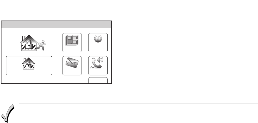
SECU
SECUSECU
SECURING THE PREMISES
RING THE PREMISESRING THE PREMISES
RING THE PREMISES
Panic Keys
Activating a panic alarm
Zones
Arm Away
Ready To Arm
Arm Stay
MoreDelay
Phone
10:18 AM June 8, 2010
5000-100-006-V0
Message
System
1. With the system in the disarmed or armed
state, depress and hold the “Panic” key for
until the system displays the Panic screen
(approximately 3-4 seconds).
Ready To Arm
5000-100-068-V0
Police Fire Medical
2. Touch the desired panic icon on the screen
and if prompted, enter a valid User Code on
the displayed keypad.
3. The alarm will sound and the keypad is
displayed along with the alarm type and the
associated icon. Additionally, the system
announces the associated alarm
information.
Fire Alarm
Fire Alarm
Fire
Enter Code:
Cancel
231
564
0
897
Clear
5000-100-149-V0
– 31 –
SECURING THE PREMISES
SECURING THE PREMISESSECURING THE PREMISES
SECURING THE PREMISES
Chime Mode
Chime Mode
Your system can be set to provide you with an audible alert of the opening of a door, while it
is disarmed, by using Chime mode. When activated, three beeps will sound at the control
whenever a protected perimeter door is opened and the zone voice descriptor will be
announced. Additionally, the faulted zone information will be displayed on the home screen.
Selecting the “Zones” icon displays the open protection points. The Chime mode can be
turned on only when the system is disarmed.
Turning Chime mode On or Off
Arm Away
Ready To Arm
Arm Stay
BackDelay
Settings
10:18 AM June 8, 2010
5000-100-007-V0
Tools
1. With the system in the disarmed or armed
state, select the “Settings” icon from the
second page of the Home Screen. The
system displays the Setting screen.
Ready To Arm
RingerChimeVoice
Brightness
Contrast
Volume
Off
5000-100-008-V0
Off Off
Save
2. Select the “Chime” icon. The system will
toggle between “Off” and “On”. When “On” is
selected, the Chime mode will be active.
3. Select the “Save” button to save your new
settings.
– 32 –
SECURING THE PREMISES
SECURING THE PREMISESSECURING THE PREMISES
SECURING THE PREMISES
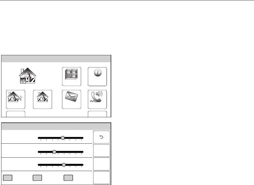
Voice Mode
Voice Mode
Your system can be set to provide you with a voice alert of system functions by activating the
Voice mode. When activated, the system will announce the system status when
armed/disarmed. The Voice mode can be turned on only when the system is disarmed.
Turning Voice mode On or Off
Zones
Arm Away
Ready To Arm
Arm Stay
MoreDelay
Phone
10:18 AM June 8, 2010
5000-100-006-V0
Message
System
1. With the system in the disarmed or armed
state, select the “Settings” icon from the
second page of the Home Screen. The
system displays the Keypad screen.
Ready To Arm
RingerChimeVoice
Brightness
Contrast
Volume
Off
5000-100-008-V0
Off Off
Save
2. Select the “Voice” icon. The system will
toggle between “Off” and “On”. When “On” is
selected, the Voice mode will be active.
3. Select the “Save” button to save your new
settings.
– 33 –
USER FUNCTIONS
USER FUNCTIONSUSER FUNCTIONS
USER FUNCTIONS
User Access
General Information
For additional security you (the Master User Code) can assign secondary user codes to
individual users enabling them to perform specific system functions. These secondary users
are identified by "User Numbers" when their codes are assigned. You can assign up to 14
user codes. Note that the Master User is the only one who can assign codes to secondary
users.
All codes can be used interchangeably when performing system functions (a system armed
with one user's code can be disarmed by another user's code), with the exception of the
Babysitter Code described below.
• Babysitter Code: This code can be used to arm the system, but cannot disarm the
system unless the system was armed with this code. This code is typically assigned to
someone (such as a babysitter) who needs to arm/disarm the system only at certain
times.
• Duress Code: This feature is intended for use when you are forced to disarm or arm the
system under threat. When used, the system will act normally, but can silently notify the
alarm monitoring company of your situation, if that service has been provided. The
Duress Code is useful only when the system is connected to an alarm
monitoring company.
IMPORTANT: Temporary users of the system (e.g., babysitters, cleaning staff) should not
be shown how to use any system function they do not need to know, such as bypassing
protection zones for example.
False Alarm Prevention Feature
The system prevents User Codes (including the Duress Code) from being duplicated. If you have
attempted to assign a duplicate 4-digit code, the entry will be rejected. Any previous existing code will
remain unchanged. Choose a different new 4-digit code and repeat the procedure.
Adding a User
Arm Away
Ready To Arm
Arm Stay
BackDelay
Settings
10:18 AM June 8, 2010
5000-100-007-V0
Tools
1. With the system in the disarmed state,
select the “Tools” icon from the second page
of the Home Screen. The system displays
the Keypad screen.
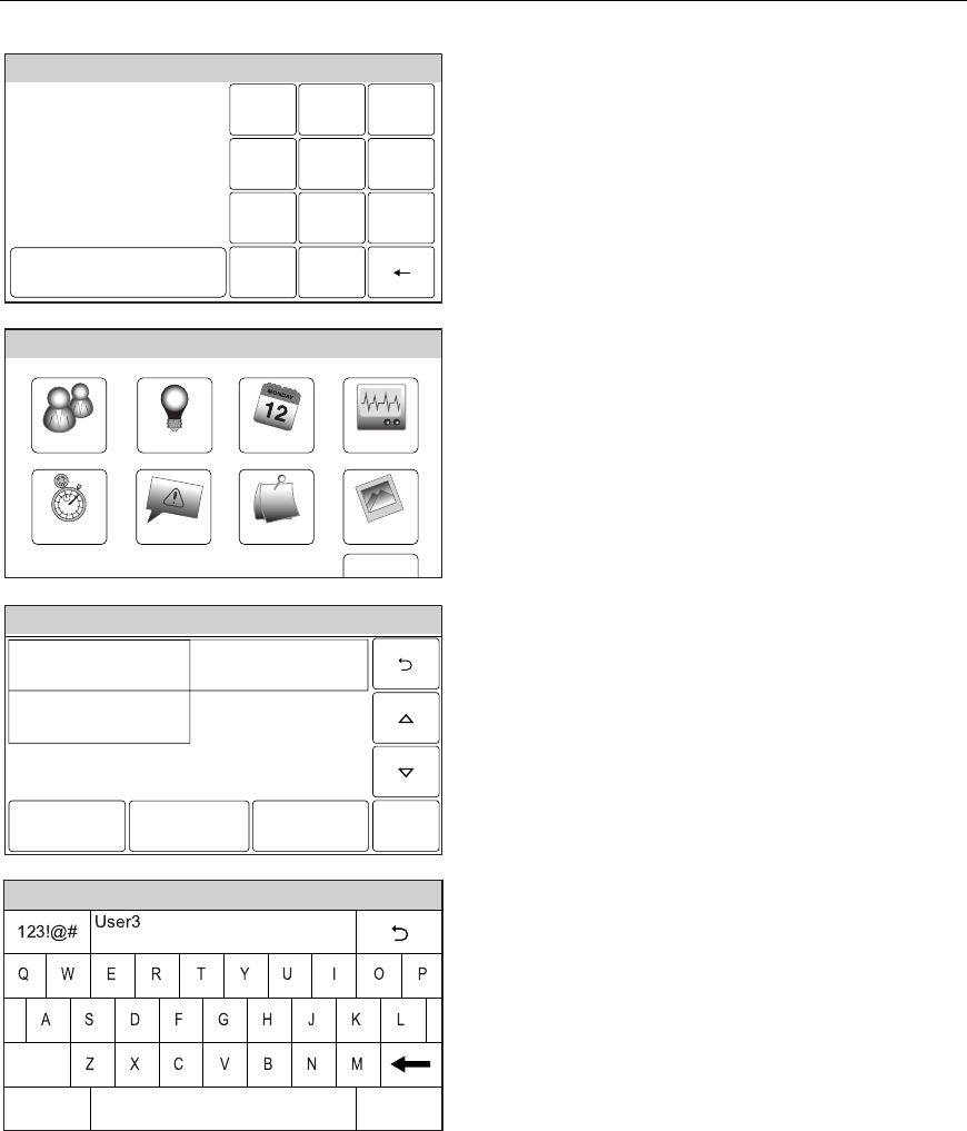
– 34 –
USER FUNCTIONS
USER FUNCTIONSUSER FUNCTIONS
USER FUNCTIONS
User Access
Ready To Arm
Program the system
Enter Code:
Cancel
5000-100-009-V0
231
564
0
897
Clear
2. Enter your 4-digit Master User Code. The
system displays the Master User
programming screen.
Slide ShowDate Time
Ready To Arm
Events
Back
Reminders
TestSchedulesDevicesUsers
5000-100-070-V0
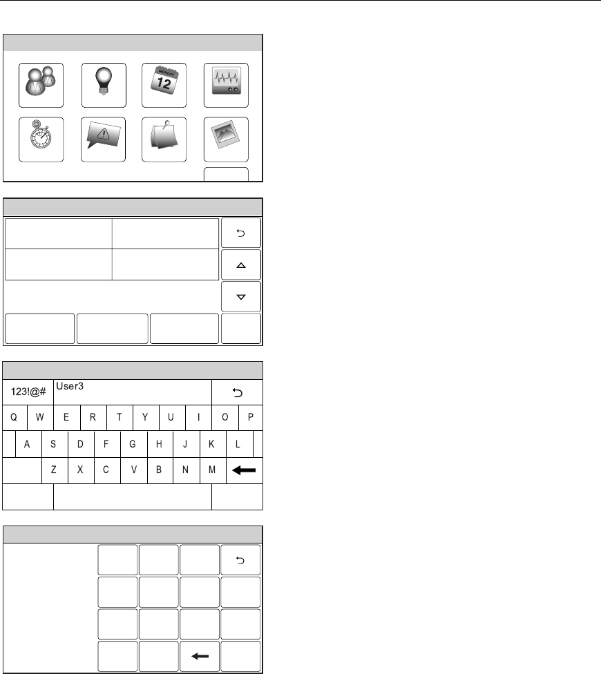
3. Select the “Users” icon. The system displays
the Master User screen.
Ready To Arm
5000-100-069-V0
Master **** Babysitter ****
Edit Add New Delete
Duress ****
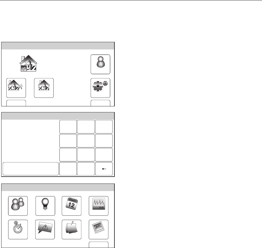
4. Select the “Add New” key. The system
displays a keyboard.
Note: **** appears to the right of User name after a
valid 4-digit User Code has been assigned to a
specific User.
Ready To Arm
5000-100-081-V0
Clear
Done
abc...
5. If desired you can enter a User Name.
Select the “Clear” key and then enter up to
20 characters of text.
Note: Select the “ABC…” key to switch the keyboard
between upper/lower case or the “123!@#” key
to switch to numbers.
6. Once you are finished, select “Done”. The
system displays the Keypad screen.
– 35 –
USER FUNCTIONS
USER FUNCTIONSUSER FUNCTIONS
USER FUNCTIONS
User Access
Ready To Arm
231
564
0
897
Clear
5000-100-185-V0
Enter Code
Done
Ready To Arm
5000-100-142-V0
Master ****
Thomas ****
Babysitter ****
Edit Add New Delete
Duress ****
7. Enter the 4-digit code for the new User
followed by “Done”. The system returns to
the Users screen and the new User is
displayed.
Editing/Deleting a User
Arm Away
Ready To Arm
Arm Stay
BackDelay
Settings
10:18 AM June 8, 2010
5000-100-007-V0
Tools
1. With the system in the disarmed state,
select the “Tools” icon from the second page
of the Home Screen. The system displays
the Keypad screen.
Ready To Arm
Program the system
Enter Code:
Cancel
5000-100-009-V0
231
564
0
897
Clear
2. Enter your 4-digit Master User Code. The
system displays the Master User
programming screen.
– 36 –
USER FUNCTIONS
USER FUNCTIONSUSER FUNCTIONS
USER FUNCTIONS
User Access
Slide ShowDate Time
Ready To Arm
Events
Back
Reminders
TestSchedulesDevicesUsers
5000-100-070-V0
3. Select the “Users” icon. The system displays
the Users screen.
Ready To Arm
5000-100-142-V0
Master ****
Thomas ****
Babysitter ****
Edit Add New Delete
Duress ****
4. Select a User Name and then select “Edit”
or “Delete”. If you are editing user
information proceed to step 5. If you are
deleting a user, proceed to step 8.
Ready To Arm
5000-100-081-V0
Clear
Done
abc...
5. If desired you can revise a User Name.
Select the “Clear” key and then enter the
desired text.
6. Once you are finished, select “Done”. The
system displays the Keypad screen. If your
wish to change the assigned User Code,
proceed to Step 7 otherwise proceed to Step
9.
Ready To Arm
231
564
0
897
Clear
5000-100-185-V0
Enter Code
Done
7. If desired, enter a new 4-digit code for the
selected User followed by “Done”. The
system returns to the Users screen.
8. Select “Yes” or “No” when the confirmation
screen is displayed then proceed to step 9.
9. Select the 2 icon to return to the Master
User screen.
– 37 –
USER FUNCTIONS
USER FUNCTIONSUSER FUNCTIONS
USER FUNCTIONS
View Events
This feature can be used to view a number of System Events including Arming/Disarming,
Zone Activity, Troubles and Alarms.
Viewing System Events
Arm Away
Ready To Arm
Arm Stay
BackDelay
Settings
10:18 AM June 8, 2010
5000-100-007-V0
Tools
1. With the system in the disarmed state,
select the “Tools” icon from the second page
of the Home Screen. The system displays
the Keypad screen.
Ready To Arm
Program the system
Enter Code:
Cancel
5000-100-009-V0
231
564
0
897
Clear
2. Enter your 4-digit Master User Code. The
system displays the Master User
programming screen.
Slide ShowDate Time
Ready To Arm
Events
Back
Reminders
TestSchedulesDevicesUsers
5000-100-070-V0
3. Select the “Events” icon. The Events screen
will appear and displays all events.
– 38 –
USER FUNCTIONS
USER FUNCTIONSUSER FUNCTIONS
USER FUNCTIONS
View Events
5000-100-072-V0
Sun Jun 13, 2010 15:08
Disarmed
User 2 E 441
Sat Jun 12, 2010 11:15
Armed Stay
User 1 R 441
Sat Jun 12, 2010 11:08
Burglary Bypass
Zone 3 E 570
Sat Jun 12, 2010 10:15
Disarmed
User 1 E 401
Fri Jun 11, 2010 18:08
Armed Away
User 2 R 401
Fri Jun 11, 2010 12:10
Disarmed
User 3 E 441
Fri Jun 11, 2010 11:08
Armed Stay
User 2 R 441
Fri Jun 11, 2010 10:15
Burglary Bypass
Zone 3 E 570
Ready To Arm
All
4. If you wish to view specific system history,
select “All”. The system displays a new
menu.
Ready To Arm
5000-100-071-V0
All
Bypass
Non
Security
Alarm
Open
or Close
Trouble
5. Select from the menu to display the specific
event types that you wish to view.
Note: Only the event types that were
programmed by your installer are
available for viewing.
– 39 –
USE
USEUSE
USER FUNCTIONS
R FUNCTIONSR FUNCTIONS
R FUNCTIONS
Message Recording and Playback
The LYNX Touch Message Center allows you to record, play and delete messages. The
maximum message duration is 180 seconds.
NOTES: (1) If the system loses electrical power, all messages will be erased.
(2) Message Play/Record will not be available if a report must be sent.
Entering message mode
Zones
Arm Away
Ready To Arm
Arm Stay
MoreDelay
Phone
10:18 AM June 8, 2010
5000-100-006-V0
Message
System
1. With the system in the disarmed state,
select the “Message” icon from the Home
Screen. The system displays the Message
screen.
Recording a message
Ready To Arm
Save
5000-100-045-V0
Add New Delete All
Play
1. Select “Add New”. The system displays the
Record Message screen.
Ready To Arm
5000-100-047-V0
Message 2 Stopped
Record DeletePlay
2. Select “Record”, the system will sound a
single tone. Speak into the microphone and
record your message.
3. When you are finished recording your
message, select. “Stop”
4. To listen to the message, select “Play”.
5. If you wish to delete the message, select
“Delete”.
– 40 –
USER FUNCTIONS
USER FUNCTIONSUSER FUNCTIONS
USER FUNCTIONS
Message Recording and Playback
5000-100-046-V0
Message 1 2:48 PM September 1, 2010
Message 2 5:09 PM September 5, 2010
Add New Delete AllPlay
Ready To Arm
6. When you have finished recording, select
“2”. The system displays the recorded
messages.
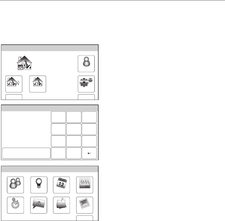
7. To record additional messages (if recording
time is available) repeat steps 1 through 3.
NOTE: If you are trying to record a new message and the message center is already full, “Add New” will not
be displayed. If the message center is full all old messages must be deleted before new messages
can be recorded. See Deleting Messages section.
Playing a message(s)
5000-100-046-V0
Message 1 2:48 PM September 1, 2010
Message 2 5:09 PM September 5, 2010
Add New Delete AllPlay
Ready To Arm
1. At the Message screen, select the
message you wish to play.
2. Select “Play”, the system plays your
message.
3. When you are finished listening to the
message, you may select. “Stop”. If “Stop”
is not selected the system continues to
play the remaining messages.
4. When you have finished listening to the
messages, select “2”. The system returns
to the Home Screen.
Deleting messages
5000-100-046-V0
Message 1 2:48 PM September 1, 2010
Message 2 5:09 PM September 5, 2010
Add New Delete AllPlay
Ready To Arm
1. At the Message screen, select “Delete All”.
The system deletes all messages.
2. When you have finished deleting the
messages, select “2”. The system returns
to the Home Screen.
– 41 –
USER FUNCTIONS
USER FUNCTIONSUSER FUNCTIONS
USER FUNCTIONS
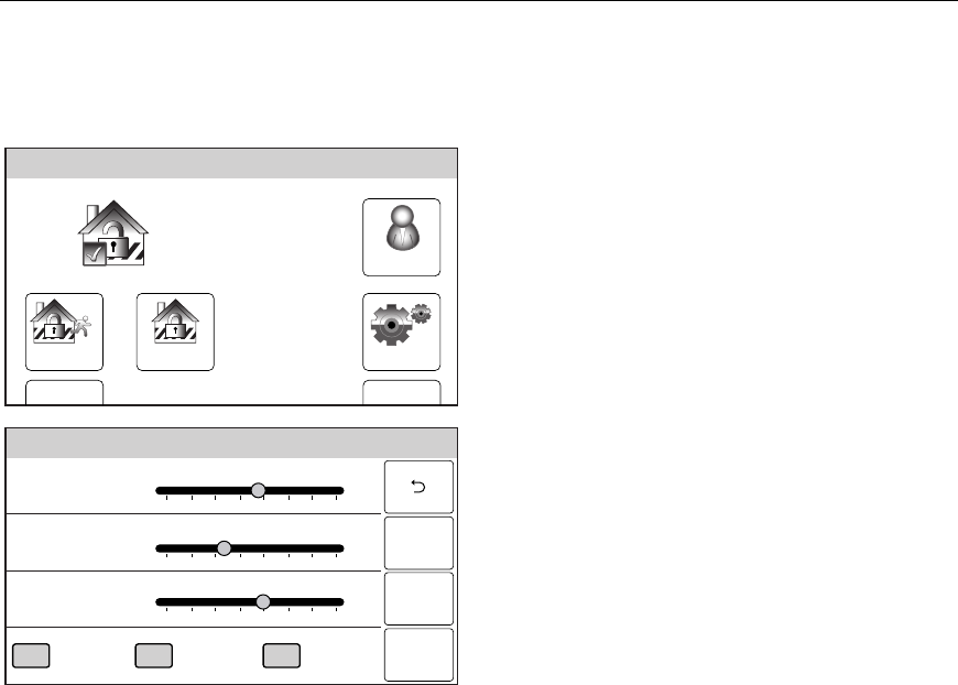
System Adjustments
The volume level of message playback, system announcements, and status beeps can be
changed if desired. Additionally, you can adjust the display’s brightness and contrast and
turn on or off the Chime or turn off the telephone Ringer.
Arm Away
Ready To Arm
Arm Stay
BackDelay
Settings
10:18 AM June 8, 2010
5000-100-007-V0
Tools
1. With the system in the disarmed or armed
state, select the “Settings” icon from the
second page of the Home Screen. The
system displays the Settings screen.
Ready To Arm
RingerChimeVoice
Brightness
Contrast
Volume
Off
5000-100-008-V0
Off Off
Save
2. Increase or decrease the Display Brightness
or Contrast or the System Volume by using
the sliding adjustment from left (decrease) to
right (increase).
3. Turn On or Off the Voice, Chime or
telephone Ringer by selecting the
appropriate icon. The system toggles
between “On” and “Off”.
4. Select “Save” when you are finished. The
system returns to the second page of the
Home Screen.
– 42 –
USER FUNCTIONS
USER FUNCTIONSUSER FUNCTIONS
USER FUNCTIONS
Clock/Calendar
Note: If your system is equipped with a GSMVLP5 or ILP5 Communication Module, the time and date will
be programmed and updated automatically via Central Station. You may still program the correct
Time Zone as shown below. Check with your installer to see if your system is equipped with a
Communications Module.
Setting the date and time
Arm Away
Ready To Arm
Arm Stay
BackDelay
Settings
10:18 AM June 8, 2010
5000-100-007-V0
Tools
Note: The system must be disarmed in order
to set the date and time.
1. With the system in the disarmed state,
select the “Tools” icon from the second page
of the Home Screen. The system displays
the Keypad screen.
Ready To Arm
Program the system
Enter Code:
Cancel
5000-100-009-V0
231
564
0
897
Clear
2. Enter your 4-digit Master User Code. The
system displays the Master User
programming screen.
Slide ShowDate Time
Ready To Arm
Events
Back
Reminders
TestSchedulesDevicesUsers
5000-100-070-V0
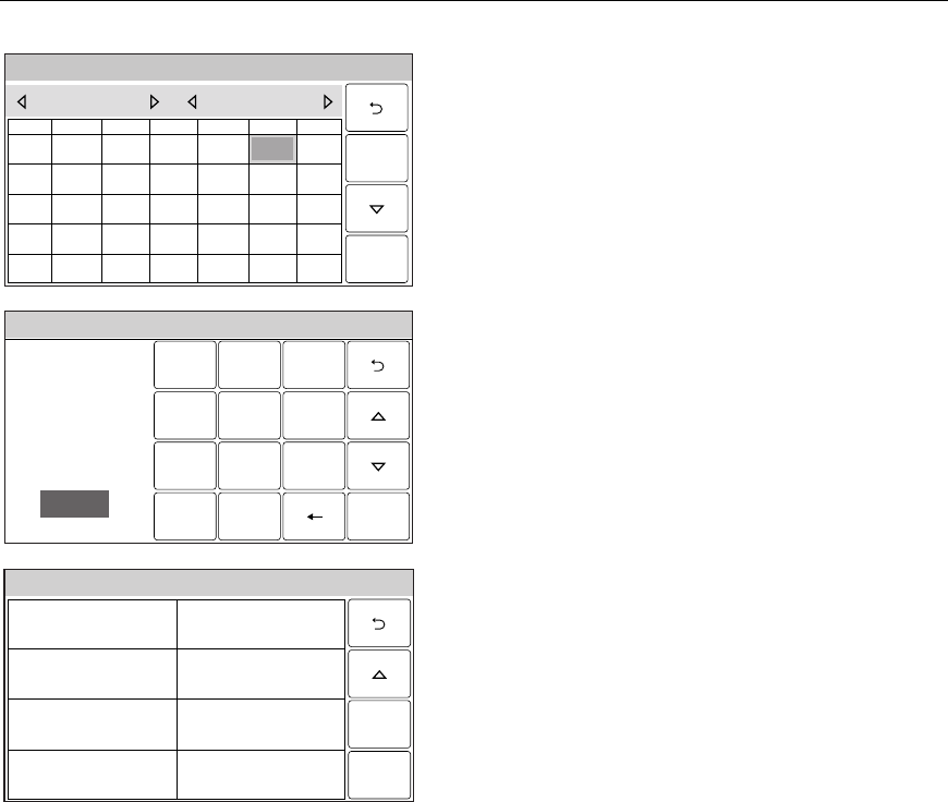
3. Select the “Date Time” icon. The Calendar
screen will appear.
– 43 –
USER FUNCTIONS
USER FUNCTIONSUSER FUNCTIONS
USER FUNCTIONS
Clock/Calendar
System Programming...
5000-100-016-V0
THUSUN WED
32
SAT
6
FRI
5
TUEMON
1
1817
20
191614 15
2524
27
262321 22
3028 29
1110
13
129
78
June 2010
4
Save
4. Select the correct month by using the “W”
and “X”.
5. Select the correct year by using the “W” and
“X”.
6. Select the correct day on the calendar.
7. When you have finished select the “T” icon.
The system advances to the time screen.
System Programming
231
564
0
897
Clear
5000-100-010-V0
AM / PM
Enter Time
10:21 AM
Save
8. If the displayed time is not correct, select
“Clear” then enter the correct time (4 digits)
on the keypad and select AM or PM.
9. When you have finished select the “T” icon.
The system advances to the next screen OR
proceed to step 17.
5000-100-022-V0
Time Zone
Eastern (EST)
Day Light Savings Time
Yes
Start Month
March
End Month
November
Start Week
Second
End Week
First
Save
Ready To Arm
10. Select “Time Zone”. The system scrolls
between through the following options:
Eastern (EST)
Central (CST)
Mountain (MST)
Pacific (PST)
Hawaii (HAST)
Alaska (AKST)
Select the correct time zone.
11. Select “Day Light Savings Time”. The
system toggles between “Yes” and “No”.
Note: The start month/week and end month week are
default programmed to “March/Second” and
“November/First” respectively. Steps 13 to 16
should only be performed if you wish to change
those entries. If you are not changing the
defaults, advance to step 17.

– 44 –
USER FUNCTIONS
USER FUNCTIONSUSER FUNCTIONS
USER FUNCTIONS
Clock/Calendar
Ready To Arm
5000-100-075-V0
January February
March April
May June
July August
12. Select “Start Month”. The system displays a
calendar. Select the correct month.
13. Select “Start Week”. The system will toggle
between:
Second
Third
Fourth
First
14. Select “End Month”. The system displays a
calendar. Select the correct month.
15. Select “End Week”. The system will toggle
between:
First
Second
Third
Fourth
16. When you are finished select the “Save”
key. The system returns to the Master User
program screen.
– 45 –
USER FUNCTIONS
USER FUNCTIONSUSER FUNCTIONS
USER FUNCTIONS
Scheduling User Interface
The Scheduling Feature can be used to program the system to automatically perform certain
functions (i.e.; automatically arming the system in Stay mode and activating output devices).
Programming a Scheduled Function
Arm Away
Ready To Arm
Arm Stay
BackDelay
Settings
10:18 AM June 8, 2010
5000-100-007-V0
Tools
1. With the system in the disarmed state,
select the “Tools” icon from the second page
of the Home Screen. The system displays
the Keypad screen.
Ready To Arm
Program the system
Enter Code:
Cancel
5000-100-009-V0
231
564
0
897
Clear
2. Enter your 4-digit Master User Code. The
system displays the Master User
programming screen.
Slide ShowDate Time
Ready To Arm
Events
Back
Reminders
TestSchedulesDevicesUsers
5000-100-070-V0
3. Select the “Schedules” icon. The system
displays the Scheduling screen.
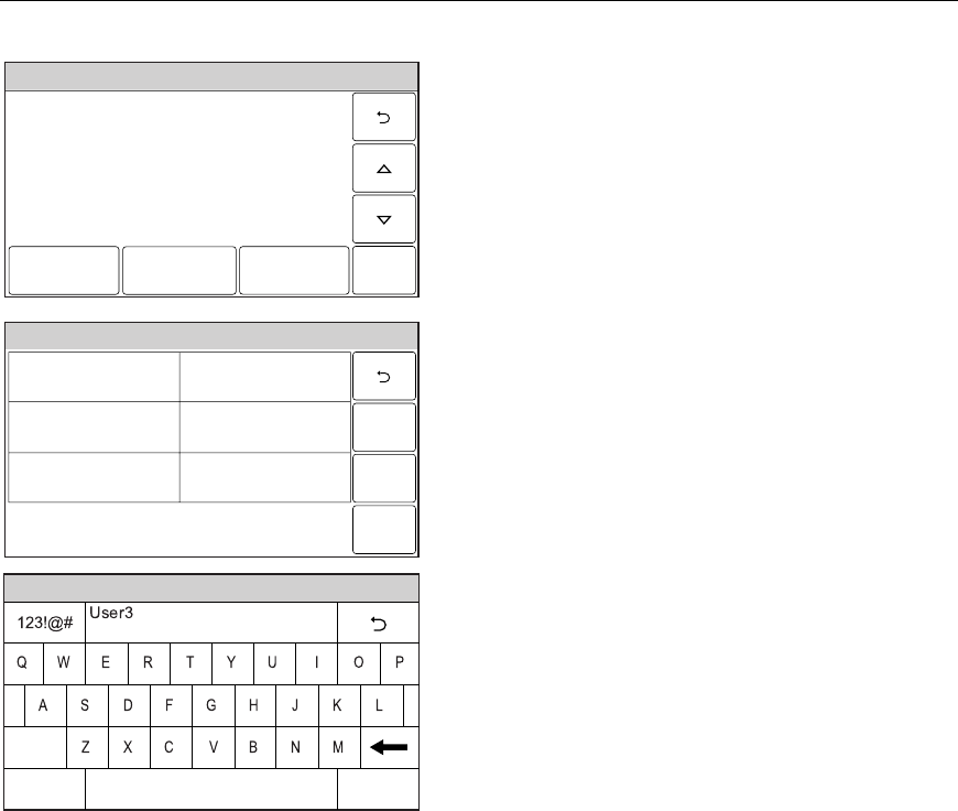
– 46 –
USER FUNCTIONS
USER FUNCTIONSUSER FUNCTIONS
USER FUNCTIONS
Scheduling User Interface
Ready To Arm
5000-100-146-V0
Edit Delete
Add New
4. Select “Add New”. The system displays the
scheduling options screen.
Ready To Arm
5000-100-144-V0
Save
Frequency
None
Type
None
Name
5. Select “Name”. The system displays a
keypad.
Ready To Arm
5000-100-081-V0
Clear
Done
abc...
6. Enter a name for the scheduled function on
the displayed keypad then select “Done”.
7. Select “Frequency” then select one of the
following displayed options:
None Once
Daily Weekday
Weekly Monthly
8. Program the following options based upon
the Frequency selected in step 7:
Once Date
Weekday Start Time
Weekly Days of the Week
Monthly Day of the Month
9. Select “Type” then scroll through and select
one of the following options:
None
Auto Stay
Output
Disarm Notification
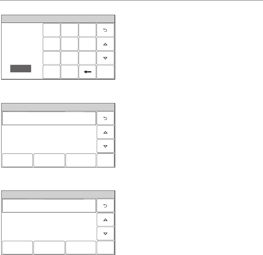
– 47 –
USER FUNCTIONS
USER FUNCTIONSUSER FUNCTIONS
USER FUNCTIONS
Scheduling User Interface
Ready To Arm
231
564
0
897
Clear
5000-100-147-V0
AM / PM
Enter Time
10:21 AM
Done
10. If Auto Stay is selected, select “Clear” then
enter a 4-digit time on the displayed keypad
then select “Save”. If “Output” is selected
proceed to Step 11. If “Disarm Notification”
is selected proceed to Step 12.
11. Select a Device (Device 1 through Device
16).
12. Enter a Start Time and End Time on the
displayed keypad then select “Save”.
Editing a Scheduled Function
Ready To Arm
5000-100-179-V0
Auto Arm -Auto Stay -Daily
Edit Delete
Add New
1. At the Schedules screen, select the
Schedule you wish to edit.
2. Select the “Edit” button. The Schedule
programming screen will appear. Follow the
steps as noted above in the programming a
Scheduled Function section to edit and
save your changes.
Deleting a Scheduled Function
Ready To Arm
5000-100-179-V0
Auto Arm -Auto Stay -Daily
Edit Delete
Add New
1. At the Schedule s screen, select the
Schedule you wish to delete.
2. Select the “Delete” button. A confirmation
screen will be displayed. Select “Yes” to
confirm the deletion.
3. Select the “2” button. The system returns
to the Master User programming screen.
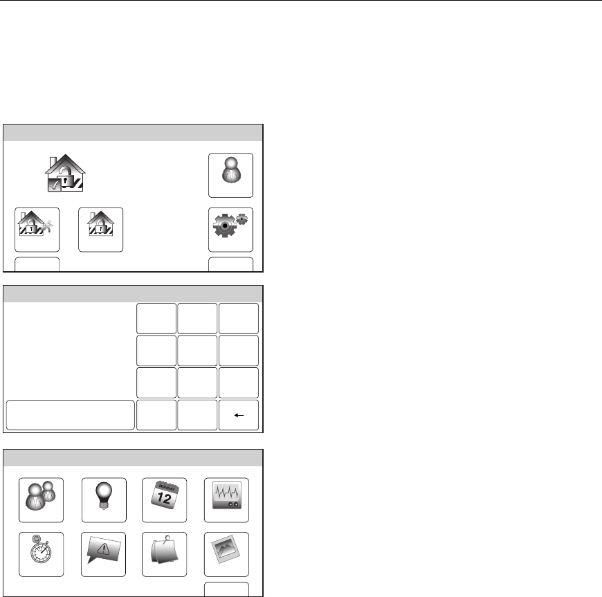
– 48 –
USER FUNCTIONS
USER FUNCTIONSUSER FUNCTIONS
USER FUNCTIONS
Reminders
The Reminder Feature can be used to program/record reminders that can be displayed on the
touchscreen, announced by the control and/or sent to one ort two pre-programmed phone
number(s). Check with your installer to see if the latter feature has been programmed on
your control.
Programming a Reminder
Arm Away
Ready To Arm
Arm Stay
BackDelay
Settings
10:18 AM June 8, 2010
5000-100-007-V0
Tools
1. With the system in the disarmed state,
select the “Tools” icon from the second page
of the Home Screen. The system displays
the Keypad screen.
Ready To Arm
Program the system
Enter Code:
Cancel
5000-100-009-V0
231
564
0
897
Clear
2. Enter your 4-digit Master User Code. The
system displays the Master User
programming screen.
Slide ShowDate Time
Ready To Arm
Events
Back
Reminders
TestSchedulesDevicesUsers
5000-100-070-V0
3. Select the “Reminders” icon. The system
displays the Reminders screen.
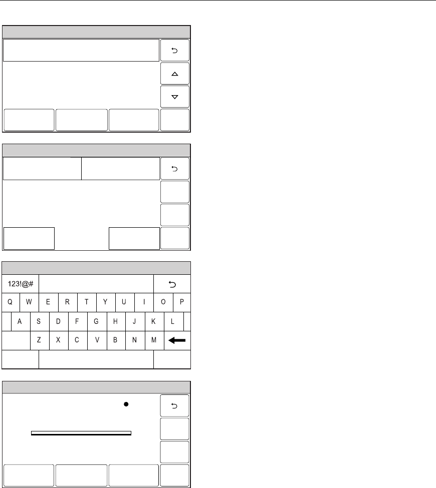
– 49 –
USER FUNCTIONS
USER FUNCTIONSUSER FUNCTIONS
USER FUNCTIONS
Reminders
Ready To Arm
5000-100-178-V0
Edit
No items to display!
Delete
Add New
4. Select “Add New”. The system displays the
Reminder programming screen.
Ready To Arm
Save
5000-100-176-V0
Name Frequency
None
Voice
No
Acknowledge
No
Ready To Arm
5000-100-180-V0
Clear
Done
abc...
5. Select “Name”. Enter a name for the
scheduled function on the displayed keypad
then select “Done”.
6. Select “Frequency” then select one of the
following displayed options:
None Once
Daily Weekday
Weekly Monthly
7. Program the following options based upon
the Frequency selected in step 6:
Once Date/Start Time
Daily Start Time
Weekday Start Time
Weekly Days of the Week/Start Time
Monthly Day of the Month/Start Time
Ready To Arm
5000-100-182-V0
Reminders 1 Stopped
Record DeletePlay
8. If a voice reminder is desired, select
“Voice”. The system toggles between “No”
and “Yes”. If yes is selected, the record
reminders screen appears.
9. Select the “Record” button and record your
reminder. When you are finished select the
“Stop” button followed by the “2” button.
The system returns to the Reminder
programming screen.
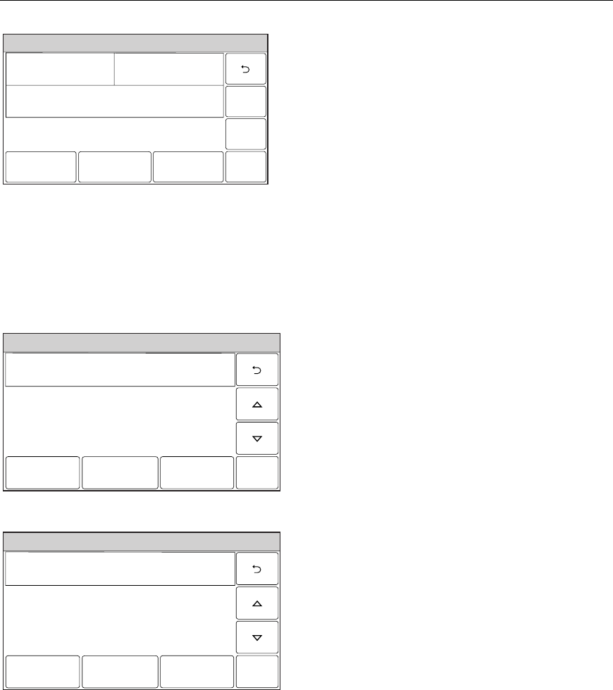
– 50 –
USER FUNCTIONS
USER FUNCTIONSUSER FUNCTIONS
USER FUNCTIONS
Reminders
Ready To Arm
Save
5000-100-183-V0
Start Time
3:00 PM
Date
January 1, 2011
Frequency
Once
Name
Walk Dog
Voice
No
Follow Me
Disabled
Acknowledge
No
10. If a “Follow Me” phone number(s) was
programmed by your installer you can send
a reminder to the phone number(s). Select
“Follow Me” option. The system toggles
between “Disabled”, “To Ph. 1”, “To Ph. 2”
and “To Ph. 1 & 2”, as applicable.
Note: For important reminders you should
program the “Acknowledge” option.
When this option is selected, the
reminder will continue to play until it is
acknowledged.
11. Select the “Acknowledge” option. The
system toggles between “No and “Yes”.
12. Select “Save” when all applicable options
have been programmed.
Editing a Reminder
Ready To Arm
5000-100-184-V0
Walk Dog - Daily
Edit Delete
New
1. At the Reminders screen, select the
reminder you wish to edit.
2. Select the “Edit” button. The Reminder
programming screen will appear. Follow the
steps as noted above in the programming a
Reminder section to edit and save your
changes.
Deleting a Reminder
Ready To Arm
5000-100-184-V0
Walk Dog - Daily
Edit Delete
New
1. At the Reminders screen, select the
reminder you wish to delete.
2. Select the “Delete” button. A confirmation
screen will be displayed. Select “Yes” to
confirm the deletion.
3. Select the “2” button. The system returns
to the Master User programming screen.

– 51 –
USER FUNCTIONS
USER FUNCTIONSUSER FUNCTIONS
USER FUNCTIONS
Speaker Phone Feature
If this feature has been programmed the LYNX Touch is capable of operating as a speaker
phone. During speaker phone operation the system will provide the following functions:
• All function/event processing will continue to operate, but there will be no
announcements.
NOTE: The system will enter the Speaker Phone mode even if an alarm or trouble is stored in the system
memory.
Do not use the speaker phone as the only telephone in your home since in some special
cases the speaker phone is not functional.
The system will not enter speaker phone mode and LYNX Touch will not ring if:
• The feature has not been programmed.
• A report is being sent.
• An audible alarm is present.
• An announcement is being made or a recorded message is being played back.
• A message is being recorded.
• If the system is in test or sniffer mode.
• AC power is not present
The speaker phone will be aborted if:
• A report must be sent.
• An audible alarm or trouble has ocurred.
• AC power is lost.
Using the Speaker Phone Feature
When the LYNX Touch is operating in the Speaker Phone mode, if a zone is violated and has
triggered an entry/exit delay, the system will automatically change the touchscreen from
telephone to security mode. This allows the user to disarm the system or take other
appropriate actions in the security mode without interrupting the telephone session. To
regain telephone keypad control you will need to reactivate the telephone keypad.
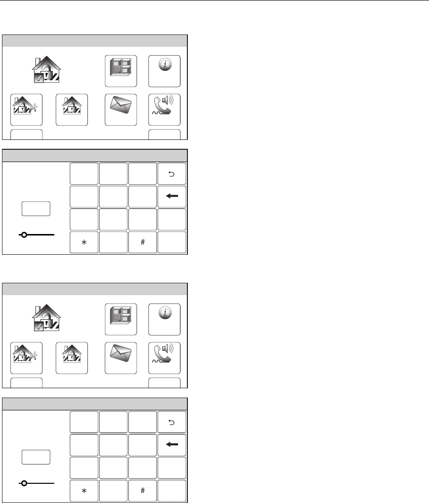
– 52 –
USER FUNCTIONS
USER FUNCTIONSUSER FUNCTIONS
USER FUNCTIONS
Speaker Phone Feature
Placing a Call
Zones
Arm Away
Ready To Arm
Arm Stay
MoreDelay
Phone
10:18 AM June 8, 2010
5000-100-006-V0
Message
System
1. With the system in the disarmed or armed
state, select the “Phone” icon from the
Home Screen. The system displays the
Keypad screen.
Ready To Arm
Talk
231
564
0
897
5000-100-148-V0
Flash
Redial
Volume
2. Select the “Talk” icon and then enter the
number you wish to dial. The “End” icon
replaces the “Talk” icon. Selecting the
“Redial” icon will allow you to redial the last
number that was dialed.
3. Select the “Flash” icon to switch between
two calls.
4. Select the “End” icon to hang up and end
the call.
Answering a Call
Zones
Arm Away
Ready To Arm
Arm Stay
MoreDelay
Phone
10:18 AM June 8, 2010
5000-100-006-V0
Message
System
1. With the system in the disarmed or armed
state, select the “Phone” icon from the
Home Screen. The system displays the
Keypad screen.
Ready To Arm
Talk
231
564
0
897
5000-100-148-V0
Flash
Redial
Volume
2. Select the “Talk” icon. The “End” icon
replaces the “Talk” icon.
3. Select the “End” icon to hang up and end
the call.

– 53 –
USER FUNCTIONS
USER FUNCTIONSUSER FUNCTIONS
USER FUNCTIONS
Remote Phone Control Feature
The LYNX Touch Series is equipped with a remote interactive phone capability that permits
access to the security system from any off-site touch-tone telephone using all user codes. The
system will provide the appropriate voice messages and any system beeping sounds
indicating the status of the security system over the phone line. (Refer to Summary of
Audible Notification for further information.) The following functions can be performed from
any remote touch-tone telephone:
• Disarm the system.
• Arm the system in STAY or AWAY mode.
• Bypass zones.
• Check system status.
The remote access session will be aborted if:
• A report must be sent.
• Any local or wireless key entry is made.
• User Code is not entered within eight (8) seconds of call pickup (during the
“system…..system announcement).
• No keys are depressed for a period of 15 seconds and while no announcement has been
made by the system. Any remote key entry will, however extend this timeout back to 15
seconds.
It will not be possible to begin a remote access session if:
• A report must be sent
• The system is in any Test mode.
• Panel is in shutdown mode (programmed by your installer).
Using Remote Phone Control Feature
Dial the controls’s phone number. If no answering machine is present, the control will pick
up between 1 and 14 rings, depending on the number programmed by your installer and will
periodically announce “SYSTEM ENTER CODE”. If an answering machine is on the
premises, you need to dial the premises and hang up on the first ring. Wait at least five (5)
seconds (but no more than 22 seconds) and dial the premises phone number again. The
control will pick up and periodically announce “SYSTEM”.

– 54 –
USER FUNCTIONS
USER FUNCTIONSUSER FUNCTIONS
USER FUNCTIONS
Remote Phone Control Feature
Remote Phone Control Commands
Enter User Code (within eight seconds). Upon entering remote phone control mode the Lynx will
announce “System, enter code”.
To remotely disarm system:........................................................... User Code + [1]
To remotely arm in AWAY mode: .................................................. User Code + [2]
To remotely arm in STAY mode: ................................................... User Code + [3]
To remotely arm in AWAY or STAY mode with no delay:.............. User Code + [2] or [3] + [0]
To remotely Bypass zones: ........................................................... User Code + [6] + zone no.
To remotely activate Forced Bypass: ............................................ User Code + [6] + [#]
To remotely check system status:.................................................. [✻]
To end remote phone session: Hang Up or ................................. User Code + [9]
Notes: (1) Check with your installer to see if the Forced Bypass mode has been enabled.
(2) When bypassing zones, make sure a confirmation beep sounds for each zone that has been
bypassed.

– 55 –
USER FUNCTIONS
USER FUNCTIONSUSER FUNCTIONS
USER FUNCTIONS
Remote Services
Your security system may be capable of providing a series of web-based services that allow
you to communicate with your security system remotely in a number of ways. These services
provide the ability to:
• Access to your security system from a computer via website (Remote Access Feature)
• Receive e-mail and text message notification of system events (Multi-Mode Feature)
• Perform system functions and receive confirmations using text messages (SMS
Feature)
Ask you installer if your system employs a remote services capable device.

– 56 –
FIRE
FIREFIRE
FIRE/CO
/CO/CO
/CO ALARM SYSTEM
ALARM SYSTEM ALARM SYSTEM
ALARM SYSTEM (If Installed)
General Information
UL
ULUL
UL
LYNX Touch is not intended for UL985 Household Fire applications unless a 24-hour
backup battery (P/N LYNXRCHKIT-SHA) is installed.
General
Your fire alarm system (if installed) is active 24 hours a day, providing continuous
protection. In the event of an emergency, the installed smoke, heat and/or carbon monoxide
detectors will automatically activate your security system, triggering a loud, intermittent
sound from the touchscreen. The sound will be interlaced with the voice descriptor, sounding
every 15 seconds. A “FIRE” or “CO” message will appear at your touchscreen and remain on
until you silence and clear the alarm display.
In Case of Fire
1. Should you become aware of a fire emergency before your detectors sense the problem, go
to the LYNX Touch and press and hold the panic key and then select the Fire icon. The alarm
will sound and an alarm will be transmitted to the central station.
2. Evacuate all occupants from the premises.
3. If flames and/or smoke are present, leave the premises and notify your local Fire Department
immediately.
4. If no flames or smoke are apparent, investigate the cause of the alarm. The zone number of
the zone(s) in an alarm condition will appear at the touchscreen.
In Case of Carbon Monoxide Alarm
1. If a high level of carbon monoxide is detected you should evacuate all occupants from the
premises and immediately move to a spot where fresh air is available, preferably outdoors.
2. From a safe area, contact your security service provider for further instructions.
Silencing a Fire/Carbon Monoxide Alarm
1. Silence the alarm by entering an OFF sequence.
2. To clear the alarm, enter a second OFF sequence.
3 If the touchscreen indicates a trouble condition after the second OFF sequence, check that
smoke detectors are not responding to smoke- or heat-producing objects in their vicinity.
Should this be the case, eliminate the source of heat or smoke.
4. If this does not remedy the problem, there may still be smoke in the detector. Clear it by
fanning the detector for about 30 seconds.
5. When the problem has been corrected, clear the display by entering another OFF sequence.
– 57 –
FIRE
FIREFIRE
FIRE/CO
/CO/CO
/CO ALARM SYSTEM
ALARM SYSTEM ALARM SYSTEM
ALARM SYSTEM
National Fire Protection Association’s
Smoke Detector Recommendations
UL
ULUL
UL
LYNX Touch is not intended for UL985 Household Fire applications unless a 24-hour
backup battery (P/N LYNXRCHKIT-SHA) is installed.
With regard to the number and placement of smoke and heat detectors, we subscribe to the
recommendations contained in the National Fire Protection Association's (NFPA) Standard
#72 noted below.
Early warning fire detection is best achieved by the installation of fire detection equipment
in all rooms and areas of the household. The equipment should be installed as follows: A
smoke detector installed outside of each separate sleeping area, in the immediate vicinity of
the bedrooms and on each additional story of the family living unit, including basements and
excluding crawl spaces and unfinished attics.
In addition, the NFPA recommends that you install heat or smoke detectors in the living
room, dining room, bedroom(s), kitchen, hallway(s), attic, furnace room, utility and storage
rooms, basements and attached garages.
DINING
KITCHEN
BEDROOM
BEDROOM
BEDROOM
BEDROOM
LIVING ROOM
BEDROOM
BDRM
DINING
LIVING ROOM
TV ROOM KITCHEN
BEDROOM BEDROOM
TO
BR
LVNG RM
BASEMENT
KTCHN
.
CLOSED
DOOR
GARAGE
Smoke Detectors for Minimum Protection
Smoke Detectors for Additional Protection
Heat-Activated Detectors
BDRM
floor_plan-001-V1
– 58 –
FIRE
FIREFIRE
FIRE/CO
/CO/CO
/CO ALARM SYSTEM
ALARM SYSTEM ALARM SYSTEM
ALARM SYSTEM
Emergency Evacuation
U
UU
UL
LL
L
LYNX Touch is not intended for UL985 Household Fire applications unless a 24-hour
backup battery (P/N LYNXRCHKIT-SHA) is installed.
Establish and regularly practice a plan of escape in the event of fire. The following steps are
recommended by the National Fire Protection Association:
1. Position your detector or your interior and/or exterior
sounders so that they can be heard by all occupants.
2. Determine two means of escape from each room. One
path of escape should lead to the door that permits
normal exit from the building. The other should be an
alternative escape, such as a window, should your path
to that door be unpassable. Station an escape ladder at
such windows if there is a long drop to the ground.
3. Sketch a floor plan of the building. Show windows, doors,
stairs and rooftops that can be used to escape. Indicate
escape routes for each room. Keep these routes free from
obstruction and post copies of the escape routes in every
room.
4. Assure that all bedroom doors are shut while you are
asleep. This will prevent deadly smoke from entering
while you escape.
5. Try the door. If the door is hot, check your alternate
escape route. If the door is cool, open it cautiously. Be
prepared to slam the door if smoke or heat rushes in.
6. When smoke is present, crawl on the ground. Do not
walk upright, since smoke rises and may overcome you.
Clearer air is near the floor.
7. Escape quickly; don't panic.
8. Establish a place outdoors, away from your house, where
everyone can meet and then take steps to contact the
authorities and account for those missing. Choose
someone to assure that nobody returns to the house —
many die going back.
•
FRONT
•
BACK
•
BATH
BEDROOM
KITCHEN
BACK DOOR
1 FLOOR
ST
BEDROOM
2 FLOOR
ND
BATH
BEDROOM
PORCH
CLOSET
BEDROOM
BEDR
emerevac
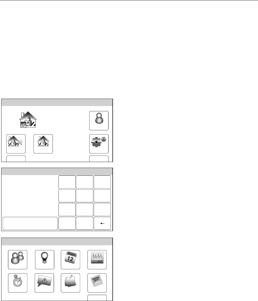
– 59 –
SYSTEM FUNCTIONS
Testing the System (to be conducted weekly)
Test Mode
The Test mode allows each protection point to be checked for proper operation. When the
Walk Test mode is active, the control sounds a single beep every 30 seconds as a reminder
that the system is in the Test mode.
NOTE: An alarm message will not be sent to your alarm monitoring company during these tests.
Entering Test Mode
Disarm the system and close all protected windows, doors, etc. The “READY” indicator
should be lit.
Testing the System
Arm Away
Ready To Arm
Arm Stay
BackDelay
Settings
10:18 AM June 8, 2010
5000-100-007-V0
Tools
1. With the system in the disarmed state,
select the “Tools” icon from the second page
of the Home Screen. The system displays
the Keypad screen.
Ready To Arm
Program the system
Enter Code:
Cancel
5000-100-009-V0
231
564
0
897
Clear
2. Enter your 4-digit Master User Code. The
system displays the Master User
programming screen.
Slide ShowDate Time
Ready To Arm
Events
Back
Reminders
TestSchedulesDevicesUsers
5000-100-070-V0
3. Select the “Test” icon. The system displays
the Test screen.
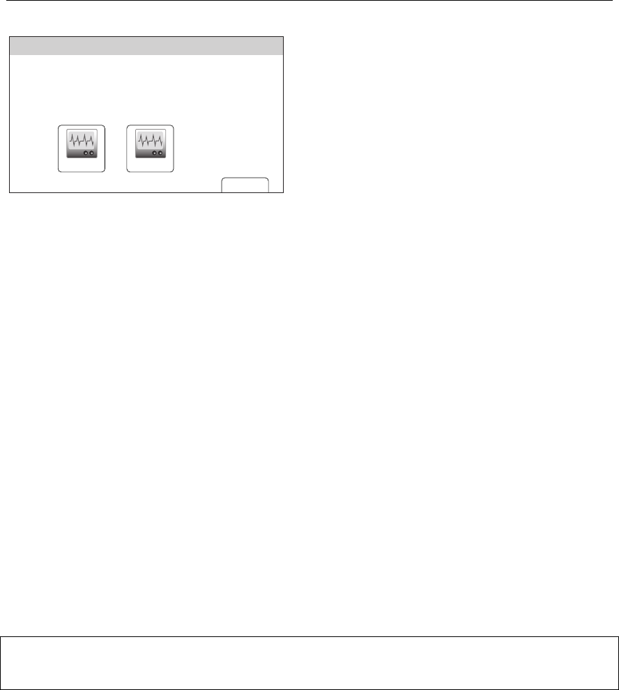
– 60 –
SYSTEM FUNCTIONS
Testing the System (to be conducted weekly)
Ready To Arm
Back
5000-100-076-V0
Version Number: CA01.00EXX
CRC Number: 0X877D
RF Version Number: 0.44
Walk Test Dialer Test
4. Select the “Walk Test” or “Dialer Test” icon.
If Walk Test is selected proceed to Step 5. If
Dialer Test is selected proceed to Step 6
5. “Walk Test…” is displayed on the system
status bar. Fault each zone as described
below.
6. If the dialer test is unsuccessful the system
will display a Reporter Failure message.
Contact your security service provider.
Walk Test
FAULT ZONES. Open each protected door and window in turn and listen for three beeps
from the control, followed by the zone’s Voice Descriptor, if it is programmed. Identification
of each faulted protection point should appear on the display. The display will clear when the
door or window is closed.
Walk in front of any interior motion detectors (if used) and listen for three beeps and/or voice
descriptors, if programmed. The identification of the detector should appear on the display
when it is activated, and its voice descriptor will be announced (if programmed). The display
will clear when no motion is detected. Note that if wireless motion detectors are used, in
order to conserve battery life, there is a 3-minute delay between activations.
To test all smoke detectors, follow the manufacturer's instructions. The identification of each
detector should appear on the display when each is activated.
If a problem is experienced with any protection point (no confirming sounds, no display),
notify your service company.
When all protection points have been checked and are intact (closed), there should be no zone
identification numbers displayed on the touchscreen.
Exiting Test Mode
When testing is completed, exit the Walk Test or Dialer Test mode by entering an Off
sequence.
NOTE: If the Walk Test mode is inadvertently left active, it automatically turns off after 4 hours. The Dialer
Test mode will remain active until exited via an Off sequence.
LYNX Touch SIA Exit/Entry Delay Times
The LYNX Touch SIA will send an event code to the Central Station after entering and after
exiting from Test mode.

– 61 –
SYSTEM FUNCTIONS
Maintaining your system
The components of your security system are designed to be as maintenance-free as possible.
To make sure that your system is in working condition, do the following:
1. Test your system weekly.
2. Test your system after any alarm occurs (see the TESTING THE SYSTEM section).
Routine Care
• Treat the components of your security system as you would any other electrical
equipment. Do not slam sensor-protected doors or windows.
• Keep dust from accumulating on the touchscreen and all protective sensors, particularly
on motion sensors and smoke detectors.
• The touchscreen and sensors should be cleaned carefully with a dry soft cloth. Do not
spray water or any other fluid on the units.
Low Battery Conditions in Wireless Sensors
Each wireless sensor in your system has an internal battery. The system detects low battery
conditions in wireless sensors, including smoke detectors, personal emergency transmitter,
and the portable wireless keypad, and displays a “Battery Low” message on the touchscreen,
which also beeps. A low battery in a wireless keypad is detected as soon as one of its keys is
pressed. In addition, a wireless smoke detector with a low battery also emits a "chirp" sound
approximately once every 20–30 seconds, identifying itself as the smoke detector with the
weak battery.
NOTE: A low battery message means that battery replacement in the indicated sensor(s) is due within 30
days. In the meantime, a sensor with a low battery is still operational.
To silence Low Battery Warning Tones, enter an Off sequence. The low battery message
display will remain on as a reminder. When you replace the weak battery with a fresh one,
the sensor will send a "good battery" signal to the control when the sensor is activated
(opening/closing of door, window, etc.). To clear the “Low Battery” message, enter an Off
sequence.
When replacing batteries, use only those recommended by your installer.
Alkaline batteries provide a minimum of 1 year of operation, and in most units and applications, provide 2–4
years of service. 3-volt lithium batteries may provide from 4-7 years of operation. Actual battery life will
depend on the environment in which the sensor is used, the number of signals that the transmitter in the
sensor has had to send, and the specific type of sensor. Factors such as humidity, high or low temperatures,
and large swings in temperature may all lead to the reduction of actual battery life in an installation.

– 62 –
SYSTEM FUNCTIONS
Maintaining your system
Changing the LYNX Touch Series System Battery
In the event of an AC power loss, the LYNX Touch Series is powered by a rechargeable,
nickel-metal hydride battery pack. The battery pack should be replaced when a “Battery
Low” message with no zone number is displayed.
NOTE: The battery pack (P/N LYNXRCHKIT-SC or LYNXRCHKIT-SHA) should be changed every four years
and must be replaced by a qualified service technician.
Following battery pack replacement, rechargeable batteries may take up to 48 hours to
charge. The “Battery Low” message may be displayed after one minute, however it should
clear within 4 hours or by entering Test Mode.

– 63 –
SUMMARY OF AUDIBLE & VISUAL NOTIFICATIONS
SOUND CAUSE ANNOUNCEMENT*
INTERRUPTED
FIRE ALARM (3 beeps)
OR
CARBON MONOXIDE ALARM (4 beeps)
fire alarm + zone voice descriptor
OR
Carbon monoxide alarm + zone voice descriptor
(Voice descriptor is interlaced with the sounder
and sounds every 45 seconds)
CONTINUOUS
BURGLARY/AUDIBLE EMERGENCY
ALARM
alarm + zone voice descriptor
(Voice descriptor is interlaced with the sounder
and sounds every 45 seconds)
ONE SHORT BEEP
(not repeated)
a. SYSTEM DISARM
b. SYSTEM ARMING ATTEMPT WITH AN
OPEN ZONE.
c. BYPASS VERIFY
a. disarmed–ready to arm
b. disarmed–not ready to arm
c. zones bypassed
ONE SHORT BEEP
(once every 45 secs)
a. SYSTEM IS IN TEST MODE
b. LOW BATTERY AT A TRANSMITTER
c. SYSTEM LOW BATTERY
d. FAIL TO COMMUNICATE
a. no announcement
b. low battery + zone voice descriptor
c. system low battery
d. check system
TWO SHORT
BEEPS
ARM AWAY armed away [instant] – exit now
THREE SHORT
BEEPS
a. ARM STAY OR INSTANT
b. ZONE OPENED WHILE SYSTEM IS IN
CHIME MODE.
a. armed stay [instant] – exit now
b. zone voice descriptor
RAPID BEEPING
a. TROUBLE
b. MEMORY OF ALARM
a. fault + zone voice descriptor
b. fire alarm or alarm + zone voice descriptor
SLOW BEEPING
a. ENTRY DELAY WARNING
b. EXIT DELAY WARNING
a. disarm system now
b. armed [away] [instant] – exit now
Additional Announcements:
The system will announce the following primary messages, depending on the system’s status
at the time:
• Disarmed–Ready to Arm [check system]
• Disarmed [not ready to arm]
• Armed [away] [stay] [instant] [check system] [exit now]
The system will announce the following secondary messages, depending on the system’s
status at the time:
• Fire Alarm + zone voice descriptor
• Alarm + zone voice descriptor
• Carbon Monoxide Alarm + zone voice descriptor
• Carbon Monoxide Fault + zone voice descriptor
• Fire Fault + zone voice descriptor
• Fault + zone voice descriptor Alarm + zone voice descriptor
• Low Battery + zone voice descriptor Fire Fault + zone voice descriptor
• System Low Battery
• Check System
• AC Loss
• Zones Bypassed
• Chime
Note: If there are no secondary messages, the primary status messages will be announced.
– 64 –
SUMMARY OF AUDIBLE & VISUAL NOTIFICATIONS
System Displays
The following icons will be displayed on the Home screen along with specific zone status
information (if applicable) to indicate system status.
DISPLAY DEFINITION DISPLAY DEFINITION
AC Loss
Door Open
Alarm
(intrusion)
Exit Active
Armed Away
Fire
Armed Stay
Flood
Battery Low
Glass Break
Check Zones
Medical Alarm
CO Alarm
Motion
Communication
Failure
Temperature
Disarmed Not
Ready to Arm
Trouble
Disarmed
Ready to Arm
Window Open
Reporter
Failure
90 RF Jam
Cover
Tamper
94 Phone
Line Cut
103 Comm.
Trouble

– 65 –
SUMMARY OF AUDIBLE & VISUAL NOTIFICATIONS
Zone Status Icons
The following icons may be displayed on the Zone Status screen.
ICON DEFINITION ICON
DEFINITION
Alarm
Trouble (red)
Fault (Yellow)
Bypass
Ready
LED Meanings
ARMED LED (Red): ON = System armed
OFF = System disarmed
Blinking = System armed, but a fault exists or alternating with READY LED
when AVM (VOX or Talk) or speaker phone mode is active.
READY LED (Green): ON = System disarmed, ready to arm
Blinking = System disarmed, not ready to arm (a fault exists) or alternating
with ARMED LED when AVM (VOX or Talk) or speakerphone mode is active.
Note: When the system is armed, the READY LED turns off.

– 66 –
Regulatory Agency Statements
Federal Communications Commission (FCC) Part 15
The user shall not make any changes or modifications to the equipment unless authorized by the Installation Instructions or User's
Manual. Unauthorized changes or modifications could void the user's authority to operate the equipment.
CLASS B DIGITAL DEVICE STATEMENT
NOTE: This equipment has been tested and found to comply with the limits for a Class B digital device, pursuant to part 15 of the
FCC Rules. These limits are designed to provide reasonable protection against harmful interference in a residential installation.
This equipment generates, uses and can radiate radio frequency energy and, if not installed and used in accordance with the
instructions, may cause harmful interference to radio communications. However, there is no guarantee that interference will not
occur in a particular installation. If this equipment does cause harmful interference to radio or television reception, which can be
determined by turning the equipment off and on, the user is encouraged to try to correct the interference by one or more of the
following measures:
• Reorient or relocate the receiving antenna.
• Increase the separation between the equipment and receiver.
• Connect the equipment into an outlet on a circuit different from that to which the receiver is connected.
• Consult the dealer or an experienced radio/TV technician for help.
This Class B digital apparatus complies with Canadian ICES-003.
Cet appareil numérique de la classe B est conforme à la norme NMB-003 du Canada.
Industry Canada (IC)
This device complies with RSS210 of Industry Canada. Operation is subject to the following two conditions: (1) This device may
not cause harmful interference, and (2) This device must accept any interference received, including interference that may cause
undesired operation.
Cet appareil est conforme à la partie 15 des règles de la FCC & de RSS 210 des Industries Canada. Son fonctionnement est
soumis aux conditions suivantes: (1) Cet appareil ne doit pas causer d' interferences nuisibles. (2) Cet appareil doit accepter toute
interference reçue y compris les interferences causant une reception indésirable.

– 67 –
Regulatory Agency Statements
TELEPHONE/MODEM INTERFACE
Federal Communications Commission (FCC) Part 68
This equipment complies with Part 68 of the FCC rules. On the front cover of this equipment is a label that contains the FCC
registration number and Ringer Equivalence Number (REN). You must provide this information to the telephone company when
requested.
This equipment uses the following USOC jack: RJ31X
This equipment may not be used on telephone-company-provided coin service. Connection to party lines is subject to state tariffs.
This equipment is hearing-aid compatible.
Industry Canada
NOTICE: The Industry Canada Label identifies certified equipment. This certification means that the equipment meets
telecommunications network protective, operational and safety requirements as prescribed in the appropriate Terminal Equipment
Technical Requirements document(s). The Department does not guarantee the equipment will operate to the user’s satisfaction.
Before installing this equipment, users should ensure that it is permissible to be connected to the facilities of the local
telecommunications company. The equipment must also be installed using an acceptable method of connection. The customer
should be aware that compliance with the above conditions may not prevent degradation of service in some situations.
Repairs to certified equipment should be coordinated by a representative designated by the supplier. Any repairs or alterations
made by the user to this equipment, or equipment malfunctions, may give the telecommunications company to request the user to
disconnect the equipment.
Users should ensure for their own protection that the electrical ground connections of the power utility, telephone lines and internal
metallic water pipe system, if present, are connected together, This precaution may be particularly important in rural areas.
Caution: Users should not attempt to make such connections themselves but should contact appropriate electric inspection
authority, or electrician, as appropriate.
AVIS: l’étiquette d’Industrie Canada identifie le matériel homologué. Cette étiquette certifie que le matériel est conforme aux
normes de protection, d’exploitation et de sécurité des réseaux de télécommunications, comme le prescrivent les documents
concernant les exigences techniques relatives au matériel terminal. Le Ministère n’assure toutefois pas que le matériel
fonctionnera à la satisfaction de l’utilisateur.
Avant d’installer ce matériel, l’utilisateur doit s’assurer qu’il est permis de le raccorder aux installations de l’enterprise locale de
télécommunication. Le matériel doit également être installé en suivant une méthode acceptée da raccordement. L’abonné ne doit
pas oublier qu’il est possible que la conformité aux conditions énoncées ci-dessus n’empêche pas la dégradation du service dans
certaines situations.
Les réparations de matériel nomologué doivent être coordonnées par un représentant désigné par le fournisseur. L’entreprise de
télécommunications peut demander à l’utilisateur da débrancher un appareil à la suite de réparations ou de modifications
effectuées par l’utilisateur ou à cause de mauvais fonctionnement.
Pour sa propre protection, l’utilisateur doit s’assurer que tous les fils de mise à la terre de la source d’energie électrique, de lignes
téléphoniques et des canalisations d’eau métalliques, s’il y en a, sont raccordés ensemble. Cette précaution est particulièrement
importante dans les régions rurales.
Avertissement : L’utilisateur ne doit pas tenter de faire ces raccordements lui-même; il doit avoir racours à un service
d’inspection des installations électriques, ou à un électricien, selon le cas.
Ringer Equivalence Number Notice:
The Ringer Equivalence Number (REN) assigned to each terminal device provides an indication of the maximum number of
terminals allowed to be connected to a telephone interface. The termination on an interface may consist of any combination of
devices subject only to the requirement that the sum of the Ringer Equivalence Numbers of all the devices does not exceed 5.
AVIS : L’indice d’équivalence de la sonnerie (IES) assigné à chaque dispositif terminal indique le nombre maximal de
terminaux qui peuvent être raccordés à une interface. La terminaison d’une interface téléphonique peut consister en une
combinaison de quelques dispositifs, à la seule condition que la somme d’indices d’équivalence de la sonnerie de tous les
dispositifs n’excède pas 5.
RF Exposure
WARNING: The LYNX Touch must be installed to provide a separation distance of at least 7.8 in (20 cm) from
all persons and not co-located or operated in conjunction with any other transmitter.
– 68 –
IN THE EVENT OF TELEPHONE OPERATIONAL PROBLEMS
In the event of telephone operational problems, disconnect the control by removing the plug from the
RJ31X (CA38A in Canada) telephone wall jack. We recommend that your certified installer
demonstrate disconnecting the phones on installation of the system. Do not disconnect the phone
connection inside the control/communicator. Doing so will result in the loss of your phone lines. If the
regular phone works correctly after the control/communicator has been disconnected from the phone
lines, the control/communicator has a problem and should be returned for repair. If upon disconnection
of the control/communicator, there is still a problem on the line, notify the telephone company that they
have a problem and request prompt repair service. The user may not under any circumstances (in or
out of warranty) attempt any service or repairs to the system. It must be returned to the factory or an
authorized service agency for all repairs.
– 69 –
OWNER'S INSURANCE PREMIUM CREDIT REQUEST
This form should be completed and forwarded to your homeowner's insurance carrier for possible premium credit.
A. GENERAL INFORMATION:
Insured's Name and Address:
Insurance Company: Policy No.:
LYNX Touch Series _________________________________________________ Other
Type of Alarm: Burglary Fire Both
Installed by: Serviced by:
Name Name
Address Address
B. NOTIFIES (Insert B = Burglary, F = Fire)
Local Sounding Device Police Dept. Fire Dept.
Central Station Name: _______________________________________________________________________________
Address:
Phone:
C. POWERED BY: A.C. With Rechargeable Power Supply
D. TESTING: Quarterly Monthly Weekly Other
(continued on other side)
– 70 –
OWNER'S INSURANCE PREMIUM CREDIT REQUEST (cont.)
E. SMOKE DETECTOR LOCATIONS
Furnace Room Kitchen Bedrooms Attic
Basement Living Room Dining Room Hall
F. BURGLARY DETECTING DEVICE LOCATIONS:
Front Door Basement Door Rear Door All Exterior Doors
1st Floor Windows All Windows Interior Locations
All Accessible Openings, Including Skylights, Air Conditioners and Vents
G. ADDITIONAL PERTINENT INFORMATION:
Signature: Date:

– 71 –
SERVICING INFORMATION
Your local Honeywell dealer is the person best qualified to service your alarm
system. Arranging some kind of regular service program with him is
advisable.
Your local Honeywell dealer is:
Name:
Address:
Phone:

– 72 –
WARNING!
THE LIMITATIONS OF THIS ALARM SYSTEM
While this system is an advanced design security system, it does not offer guaranteed protection against burglary or fire or other
emergency. Any alarm system, whether commercial or residential, is subject to compromise or failure to warn for a variety of
reasons. For example:
• Intruders may gain access through unprotected openings or have the technical sophistication to bypass an alarm sensor or
disconnect an alarm warning device.
• Intrusion detectors (e.g. passive infrared detectors), smoke detectors, and many other sensing devices will not work without
power. Battery operated devices will not work without batteries, with dead batteries, or if the batteries are not put in properly.
Devices powered solely by AC will not work if their AC power supply is cut off for any reason, however briefly.
• Signals sent by wireless transmitters may be blocked or reflected by metal before they reach the alarm receiver. Even if the
signal path has been recently checked during a weekly test, blockage can occur if a metal object is moved into the path.
• A user may not be able to reach a panic or emergency button quickly enough.
• While smoke detectors have played a key role in reducing residential fire deaths in the United States, they may not activate or
provide early warning for a variety of reasons in as many as 35% of all fires, according to data published by the Federal
Emergency Management Agency. Some of the reasons smoke detectors used in conjunction with this System may not work are
as follows. Smoke detectors may have been improperly installed and positioned. Smoke detectors may not sense fires that start
where smoke cannot reach the detectors, such as in chimneys, in walls, or roofs, or on the other side of closed doors. Smoke
detectors also may not sense a fire on another level of a residence or building. A second floor detector, for example, may not
sense a first floor or basement fire. Moreover, smoke detectors have sensing limitations. No smoke detector can sense every
kind of fire every time. In general, detectors may not always warn about fires caused by carelessness and safety hazards like
smoking in bed, violent explosions, escaping gas, improper storage of flammable materials, overloaded electrical circuits,
children playing with matches, or arson. Depending upon the nature of the fire and/or the locations of the smoke detectors, the
detector, even if it operates as anticipated, may not provide sufficient warning to allow all occupants to escape in time to
prevent injury or death.
• Passive Infrared Motion Detectors can only detect intrusion within the designed ranges as diagrammed in their installation
manual. Passive Infrared Detectors do not provide volumetric area protection. They do create multiple beams of protection, and
intrusion can only be detected in unobstructed areas covered by those beams. They cannot detect motion or intrusion that takes
place behind walls, ceilings, floors, closed doors, glass partitions, glass doors, or windows. Mechanical tampering, masking,
painting or spraying of any material on the mirrors, windows or any part of the optical system can reduce their detection
ability. Passive Infrared Detectors sense changes in temperature; however, as the ambient temperature of protected area
approaches the temperature range of 90° to 105°F, the detection performance can decrease.
• Alarm warning devices such as sirens, bells or horns may not alert people or wake up sleepers if they are located on the other
side of closed or partly open doors. If warning devices sound on a different level of the residence from the bedrooms, then they
are less likely to waken or alert people inside the bedrooms. Even persons who are awake may not hear the warning if the
alarm is muffled from a stereo, radio, air conditioner or other appliance, or by passing traffic. Finally, alarm warning devices,
however loud, may not warn hearing-impaired people or waken deep sleepers.
• Telephone lines needed to transmit alarm signals from a premises to a central monitoring station may be out of service or
temporarily out of service. Telephone lines are also subject to compromise by sophisticated intruders.
• Even if the system responds to the emergency as intended, however, occupants may have insufficient time to protect
themselves from the emergency situation. In the case of a monitored alarm system, authorities may not respond appropriately.
• This equipment, like other electrical devices, is subject to component failure. Even though this equipment is designed to last as
long as 10 years, the electronic components could fail at any time.
The most common cause of an alarm system not functioning when an intrusion or fire occurs is inadequate maintenance. This
alarm system should be tested weekly to make sure all sensors and transmitters are working properly.
Installing an alarm system may make one eligible for lower insurance rates, but an alarm system is not a substitute for insurance.
Homeowners, property owners and renters should continue to act prudently in protecting themselves and continue to insure their
lives and property.
We continue to develop new and improved protection devices. Users of alarm systems owe it to themselves and their loved ones to
learn about these developments.
– 73 –
– NOTES –
– 74 –
– NOTES –
– 75 –
– NOTES –
– 76 –
– NOTES –
– 77 –
– INDEX –
A
Alarm Cancelled ........................... 7, 23, 24
Alarm Exit Error .................................... 23
Alarms ....................................................... 8
Armed Indicator................................. 12, 22
Audible Emergency/Audible Alarm ....... 29
Auto Stay Feature .............................. 7, 19
Away Mode........................... 6, 9, 20, 22, 23
B
Babysitter Code .......................... 18, 20, 33
Battery..... 14, 17, 56, 57, 58, 60, 61, 62, 63
Battery Conditions ................................. 61
Battery Low ............................................ 62
Battery Pack ........................................... 62
Burglary Abort Window ........................... 7
Burglary Protection ....................... , 5, 6, 12
Bypass a Zone ........................................... 9
Bypassing Protection Zones .... 6, 27, 28, 33
C
Central Monitoring Station................ 8, 72
Checking System Status .......................... 9
Chime Mode ............................... 6, 9, 10, 31
Clock/Calendar............................ 42, 43, 44
D
Device Activation...................................... 6
Devices....................... 2, 6, 9, 20, 45, 67, 72
Dialer Test .............................................. 60
Disarm .... 7, 8, 9, 12, 18, 20, 22, 23, 24, 25,
33, 51, 63
Disarming The System and Silencing
Burglary Alarms................................. 25
Duress Code ............................................ 33
E
Entering Test Mode ................................ 59
Entry Delay........... 6, 12, 18, 20, 22, 23, 24
Exit Alarms ......................................... 7, 23
Exit Delay ................................................ 23
Exit Time Restart-Exit Delay
Restart/Reset ......................................... 7
Exit/Entry Delays ...................................... 7
F
False Alarm Prevention Feature ........ 7, 33
False Alarms ........................................ 7, 23
Features...................................................... 5
Fire Alarm .............................. 14, 26, 29, 63
Fire Alarm System................................... 56
Fire Protection ........................................... 6
H
Home Screen ..11, 15, 19, 21, 22, 25, 27, 31
Home” (Cancel) Key ................................ 15
L
LCD Display............................................. 15
Liquid Crystal Display ............................ 15
M
Master Menu ............................................ 16
Master User.......................................... 8, 33
Master User Code16, 33, 34, 35, 37, 42, 45,
48, 59
Memory of Alarm ..................................... 63
Menu ..................................................... 9, 15
Menu Screens ........................................... 16
Message Center....................5, 9, 12, 16, 39
Microphone......................................... 12, 39
Multi-Mode Feature................................. 55
N
Navigation Keys....................................... 15
No Delay ................................................... 22
P
Panic Key.............................................. 5, 56
Panic Keys ................................................ 29
Personal Emergency/Aux. Alarm............ 29
Phone Access Feature.............................. 53
Phone Control 5
– 78 –
Q
Quick Arm ...................................... 9, 18, 20
Quick Exit ................................................ 22
R
Ready Indicator................ 11, 17, 18, 20, 25
Ready LED ............................................... 17
Real-Time Clock......................................... 5
Rechargeable, Nickel-Metal Hydride
Battery Pack ........................................ 62
Record A Message...................................... 9
Reminder Feature.................................... 48
Remote Access Feature ........................... 55
Remote Interactive Phone Capability .... 53
Remote Services....................................... 55
Restart Exit Delay ..................................... 9
Restarting Exit Delay.............................. 23
S
Schedules.............................. 6, 9, 16, 45, 47
Scheduling Feature ............................. 6, 45
Security Codes ....................................... 5, 8
Security Functions..................................... 9
Servicing Information.............................. 71
Silence Alarm....................................... 9, 25
Silencing a Fire/Carbon Monoxide Alarm..
56
Silencing Low Battery Warning Tones .. 61
Silent Emergency/Silent Alarm .............. 29
Smoke Detectors .......... 6, 56, 57, 60, 61, 72
SMS Feature ............................................ 55
Speaker Phone ......... 5, 9, 10, 11, 12, 51, 65
Status Area .............................................. 15
Stay Mode................................... 6, 9, 18, 22
System Adjustments................................ 41
System Battery ........................................ 62
System Status .......................................... 17
T
Test Mode ....................................... 9, 59, 60
Time and Date................................ 9, 16, 42
Touchscreen Control ...................... 5, 10, 11
Two-Way Voice........................................... 5
Two-Way Voice Feature............................. 8
U
Unrestricted Menu................................... 16
User Access........................................... 5, 33
V
Voice Dialog................................................ 8
Volume Adjustment ................................... 9
Volume Level................................ 10, 17, 41
W
Walk Test ...........................................59, 60
Wireless Keypads................................. 5, 61
Z
Zones...............5, 6, 8, 17, 19, 27, 28, 60, 63

– 79 –
TWO YEAR LIMITED WARRANTY
Honeywell International Inc., acting through its Security & Communications business (“Seller”), 2 Corporate Center
Drive, Melville, New York 11747 warrants its products to be free from defects in materials and workmanship under
normal use and service, normal wear and tear excepted, for 24 months from the manufacture date code; provided,
however, that in the event the Buyer presents a proper invoice relating to the purchased product and such invoice
bears a date later than the manufacture date, then Seller may at its discretion, reflect the warranty period as
commencing at invoice date. Except as required by law, this Limited Warranty is only made to Buyer and may not
be transferred to any third party. During the applicable warranty period, Seller will repair or replace, at its sole
option and as the exclusive remedy hereunder, free of charge, any defective products.
Seller shall have no obligation under this Limited Warranty or otherwise if the product:
(i)is improperly installed, applied or maintained;
(ii)installed outside of stated operating parameters, altered or improperly serviced or repaired by anyone other than
the Seller/Seller’s Authorized Service/Repair Center;
(iii)damage is caused by outside natural occurrences, such as lightning, power surges, fire, floods, acts of nature, or
the like; or
(iv)defects result from unauthorized modification, misuse, vandalism, alterations of serial numbers, other causes
unrelated to defective materials or workmanship, or failures related to batteries of any type used in
connection with the products sold hereunder.
Exceptions to Warranty With Respect to Honeywell Products listed below:
Hardwire Contacts and PIRs – Seller warrants parts for hardwire contacts and PIRs in accordance with the terms of
the above limited warranty for a period of five (5) years from the manufacture date code.
EXCLUSION OF WARRANTIES, LIMITATION OF LIABILITY
THERE ARE NO WARRANTIES OR CONDITIONS, EXPRESS OR IMPLIED, OF MERCHANTABILITY, OR
FITNESS FOR A PARTICULAR PURPOSE OR OTHERWISE, WHICH EXTEND BEYOND THE DESCRIPTION
ON THE FACE HEREOF. TO THE FULLEST EXTENT PERMITTED BY LAW, IN NO CASE SHALL SELLER BE
LIABLE TO ANYONE FOR ANY (i) CONSEQUENTIAL, INCIDENTAL, INDIRECT, SPECIAL, OR PUNITIVE
DAMAGES ARISING OUT OF OR RELATING IN ANY WAY TO THE PRODUCT AND/OR FOR BREACH OF
THIS OR ANY OTHER WARRANTY OR CONDITION, EXPRESS OR IMPLIED, OR UPON ANY OTHER BASIS
OF LIABILITY WHATSOEVER, EVEN IF THE LOSS OR DAMAGE IS CAUSED BY SELLER’S OWN
NEGLIGENCE OR FAULT AND EVEN IF SELLER HAS BEEN ADVISED OF THE POSSIBILITY OF SUCH
LOSSES OR DAMAGES. Any product description (whether in writing or made orally by Seller or Seller’s agents),
specifications, samples, models, bulletin, drawings, diagrams, engineering sheets or similar materials used in
connection with the Buyer’s order are for the sole purpose of identifying the Seller’s products and shall not be
construed as an express warranty or condition. Any suggestions by Seller or Seller’s agents regarding use,
applications, or suitability of the products shall not be construed as an express warranty or condition unless
confirmed to be such in writing by Seller. Seller does not represent that the products it sells may not be
compromised or circumvented; that the products will prevent any personal injury or property loss by burglary,
robbery, fire or otherwise, or that the products will in all cases provide adequate warning or protection. Buyer
understands that a properly installed and maintained alarm may only reduce the risk of a burglary, robbery or fire
without warning, but it is not insurance or a guarantee that such will not occur or will not cause or lead to personal
injury or property loss. CONSEQUENTLY, SELLER SHALL HAVE NO LIABILITY FOR ANY PERSONAL
INJURY, PROPERTY DAMAGE OR OTHER LOSS BASED ON ANY CLAIM AT ALL INCLUDING A CLAIM THE
PRODUCT FAILED TO GIVE WARNING. However, if Seller is held liable whether directly or indirectly for any loss
or damage with respect to the products it sells, regardless of cause or origin, its maximum liability shall not in any
case exceed the purchase price of the product, which shall be fixed as liquidated damages and not as a penalty, and
shall be the complete and exclusive remedy against the Seller. Should your product become defective during the
warranty, please contact your installer to facilitate repair or replacement with Seller pursuant to the terms hereof.
Seller reserves the right to replace any defective product under warranty with new, refurbished, or remanufactured
product.

2 Corporate Center Drive, Suite 100
P.O. Box 9040, Melville, NY 11747
Copyright © 2011 Honeywell International Inc.
www.honeywell.com/security
Ê800-06894}Š
800-06894 1/11 Rev. A