Ademco 8DLLYNXTOUCH1 Wireless Control / Communicator User Manual 800 06834 ii
Honeywell International Inc. Wireless Control / Communicator 800 06834 ii
Ademco >
Contents
- 1. Installers Manual
- 2. Users Manual
Installers Manual
LYNX Touch Series
Security Systems
Installation and Setup Guide
ARMED READY
800-06834 1/11 Rev. A
PLEASE USE BOOKMARKS
TO GO TO VARIOUS
AGENCY STATEMENTS
LYNX Touch Installation and Setup Guide
- 2 -
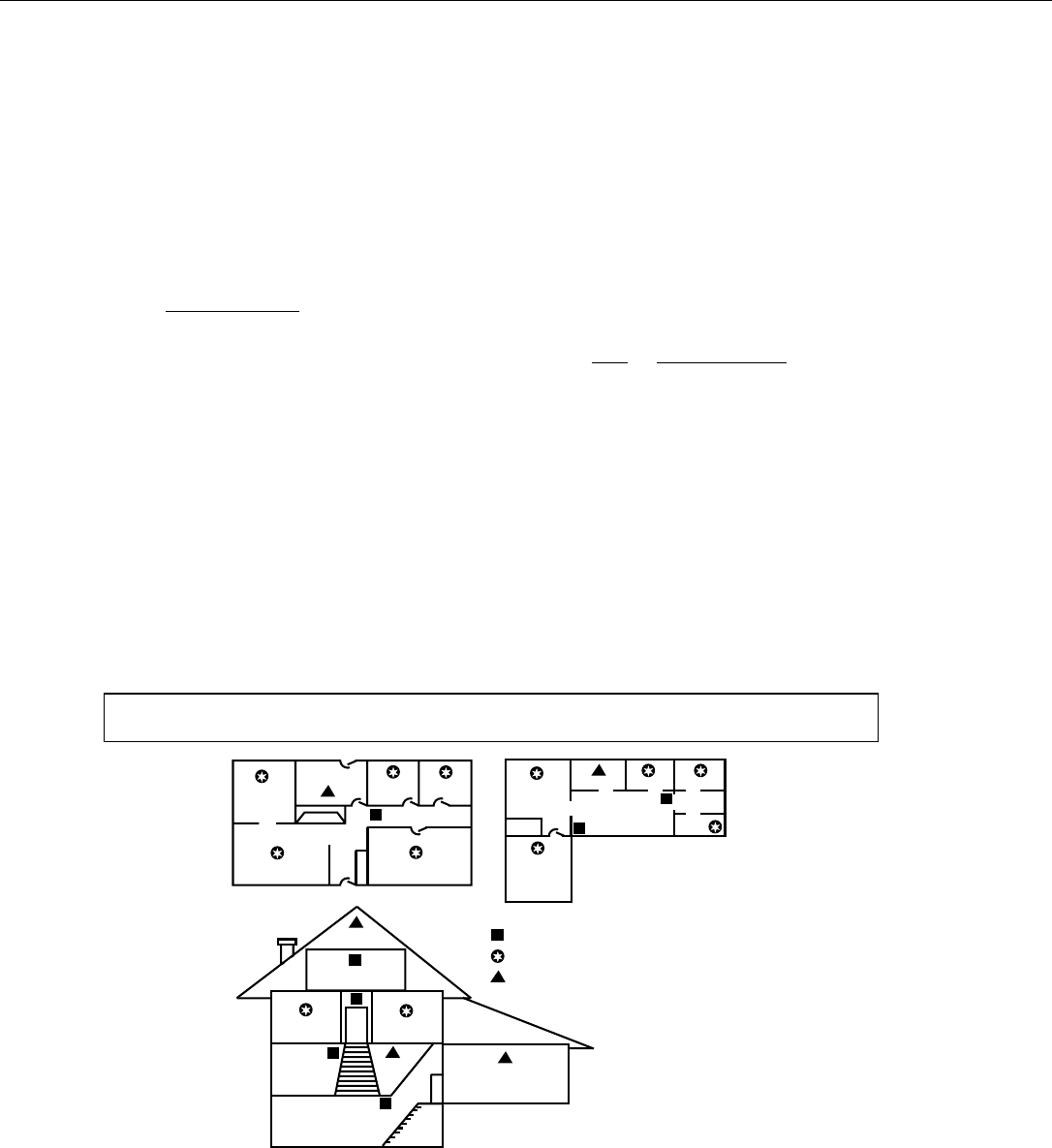
RECOMMENDATIONS FOR PROPER PROTECTION
The Following Recommendations for the Location of Fire and Burglary Detection Devices Help
Provide Proper Coverage for the Protected Premises.
Recommendations for Smoke and Heat Detectors
With regard to the number and placement of smoke/heat detectors, we subscribe to the
recommendations contained in the National Fire Protection Association's (NFPA) Standard #72
noted below.
• Early warning fire detection is best achieved by the installation of fire detection equipment in all rooms and
areas of the household as follows: For minimum protection a smoke detector should be installed outside of each
separate sleeping area, and on each additional floor of a multi-floor family living unit, including basements. The
installation of smoke detectors in kitchens, attics (finished or unfinished), or in garages is not normally
recommended.
• For additional protection the NFPA recommends that you install heat or smoke detectors in the living room,
dining room, bedroom(s), kitchen, hallway(s), attic, furnace room, utility and storage rooms, basements and
attached garages.
In addition, we recommend the following:
• Install a smoke detector inside every bedroom where a smoker sleeps.
• Install a smoke detector inside every bedroom where someone sleeps with the door partly or completely
closed. Smoke could be blocked by the closed door. Also, an alarm in the hallway outside may not wake up the
sleeper if the door is closed.
• Install a smoke detector inside bedrooms where electrical appliances (such as portable heaters, air
conditioners or humidifiers) are used.
• Install a smoke detector at both ends of a hallway if the hallway is more than 40 feet (12 meters) long.
• Install smoke detectors in any room where an alarm control is located, or in any room where alarm control
connections to an AC source or phone lines are made. If detectors are not so located, a fire within the room could
prevent the control from reporting a fire or an intrusion.
THIS CONTROL COMPLIES WITH NFPA REQUIREMENTS FOR TEMPORAL PULSE
SOUNDING OF FIRE NOTIFICATION APPLIANCES.
DINING
KITCHEN
BEDROOM
BEDROOM
BEDROOM
BEDROOM
LIVING ROOM
BEDROOM
BDRM
DINING
LIVING ROOM
TV ROOM KITCHEN
BEDROOM BEDROOM
TO
BR
LVNG RM
BASEMENT
KTCHN
.
CLOSED
DOOR
GARAGE
Smoke Detectors for Minimum Protection
Smoke Detectors for Additional Protection
Heat-Activated Detectors
BDRM
floor_plan-001-V1
Recommendations For Proper Intrusion Protection
• For proper intrusion coverage, sensors should be located at every possible point of entry to a home or
premises. This would include any skylights that may be present, and the upper windows in a multi-level
building.
• In addition, we recommend that radio backup be used in a security system. This will ensure that alarm
signals can be sent to the alarm monitoring station in the event that the telephone lines are out of order (alarm
signals are normally sent over the phone lines, if connected to an alarm monitoring station).

LYNX Touch Installation and Setup Guide
-3-
Table of Contents
System Features.....................................................................................................................................................5
Mounting the Control...........................................................................................................................................6
Wall Mounting ....................................................................................................................................................6
Desktop Mounting ..............................................................................................................................................6
Wiring Overview.................................................................................................................................................6
Wiring Connections...............................................................................................................................................7
AC Power and Backup Battery ..........................................................................................................................9
Installing/Configuring Communications Modules......................................................................................10
General ..............................................................................................................................................................10
Connecting and Configuring Communications Modules ...............................................................................10
Installing Wireless Zones...................................................................................................................................12
General Information.........................................................................................................................................12
5800 Series Transmitter Loop Numbers.........................................................................................................12
Mechanics of Programming ..............................................................................................................................15
Navigating Menus ............................................................................................................................................15
General Programming Information.................................................................................................................16
Programming ....................................................................................................................................................17
Loading Factory Defaults.................................................................................................................................17
Exiting programming Mode .............................................................................................................................17
Zone Response Type Definitions .....................................................................................................................18
General ..............................................................................................................................................................18
Programming the Control .................................................................................................................................20
Change Installer Code......................................................................................................................................20
System Type......................................................................................................................................................21
Program Date and Time...................................................................................................................................23
Program the Communications Module ...........................................................................................................24
Program Zones ..................................................................................................................................................26
Program Keys ...................................................................................................................................................28
Reporter.............................................................................................................................................................30
Sounder .............................................................................................................................................................36
System Settings ................................................................................................................................................37
Communications Diagnostics...........................................................................................................................40
Remote Programming/Control (Downloading)............................................................................................46
General Information.........................................................................................................................................46
Remote Programming Information .................................................................................................................46
System Operation ................................................................................................................................................48
Key/Touchscreen Operation.............................................................................................................................48
Panic key/Icons .................................................................................................................................................48
Security Codes ..................................................................................................................................................48
“Follow Me” System Announcement Feature .................................................................................................50
“Follow Me” Reminder Feature .......................................................................................................................51

LYNX Touch Installation and Setup Guide
- 4 -
Table of Contents (Continued)
Remote Phone Control Feature .......................................................................................................................51
System Displays................................................................................................................................................52
Zone Status Displays........................................................................................................................................52
Audio alarm Verification (Two-Way Voice Feature) ......................................................................................53
Testing the System ..............................................................................................................................................55
Event Log ..........................................................................................................................................................54
Contact ID & SIA Event Log Codes ................................................................................................................54
Test Mode ..........................................................................................................................................................55
Armed System Test ..........................................................................................................................................55
LYNX Touch Programming Default Tables...................................................................................................56
LYNX Touch SIA Programming Default Tables...........................................................................................59
Zone Programming Default Tables .................................................................................................................60
Regulatory Agency Statements........................................................................................................................63
Limitations of this System Statement ............................................................................................................64
UL Notices .............................................................................................................................................................65
SIA Quick Reference Guide ..............................................................................................................................65
Specifications .......................................................................................................................................................66
Contacting Technical Support .........................................................................................................................67
Glossary .................................................................................................................................................................68
Index .......................................................................................................................................................................69
Summary of Connections Diagram .................................................................................................................71
Warranty Information ........................................................................................................................ Rear Cover

LYNX Touch Installation and Setup Guide
- 5 -
System Features
The LYNX Touch control is a self-contained, rechargeable wireless control/communicator that features easy
installation and usage. A built-in speaker provides voice annunciation of system status along with voice
descriptors of each zone. An internal module (if provided) allows the LYNX Touch to communicate with the
Central Station via the Internet or GSM Cellular Wireless.
UL LYNX Touch is not intended for UL985 Household Fire applications unless a 24-hour backup battery (P/N
300-03866/LYNXRCHKIT-SHA) is installed.
Features
System Features
• 4.7-inch color graphic touch screen
• Message center (for user recorded messages)
• Voice announcement of system and zone status
• Voice chime
• Reminders
• Automatic stay arming
• Remote phone control
• Speaker phone operation
• “Follow me” reminder and system announcements
• 16 User Codes (Installer, Master, Babysitter,
Duress)
• 3 Panic Functions
• 16 Programmable reminders
Zones and Devices
• 64 total zones including 1 Hardwire (EOLR, N/C,
N/O) zone and up to 63 wireless zones (5800
Series transmitters)
• 2 Resident Monitor Zone Types
• Supports wireless keypads
• Built-in Case tamper
Communication
• ADEMCO Contact ID
• SIA (DC-03)
• Internet central station communication
• GSM cellular central station communication
• Two-way voice communication
• Supports AlarmNet remote services
Alarm Output
• Built-in sounder
• Steady output for burglary/panic
• Temporal (3) pulse output for fire alarms
• Temporal (4) pulse output for carbon monoxide
alarms
• Long range radio (GSM)/audio alarm verification
• Trigger output
Programming
• Options stored in EEROM
• Can be uploaded, downloaded or controlled via
IBM-compatible computer using Compass
downloader software and specified HAYES or
Honeywell CIA modem or via capable GSM or
IP communications module
• Flash downloading
Other Features
• Exit error feature (detects difference between an
actual alarm and exit alarm caused by leaving a
door open after the exit delay expires)
• Event log stores up to 128 events
• RF jam detection
• Two installer programmable user phone
numbers
System Power
• Primary Power: Plug-in Power Supply, 110VAC
to 9VDC, 2.7A output 300-04705 or 300-04065
(300-04063 in Canada)
• Backup battery: Rechargeable nickel-metal
hydride battery pack rated at 7.2Vdc. (P/N 300-
03864-1/LYNXRCHKIT-SC or 300-
03866/LYNXRCHKIT-SHA)
LYNX Touch Installation and Setup Guide
- 6 -
Mounting the Control
Wall Mounting
5000-100-091-V0
LOCKING
TABS
TIE WRAP
POINTS (2)
FRONT
CASE
BACK
CASE
MOUNTING
HOLES (4)
R OTAT E
FRONT CASE
UPWARD
TO RELEASE
HOOKS
TIE WRAP
POINT (3)
MOUNTING
HOOKS (HINGES)
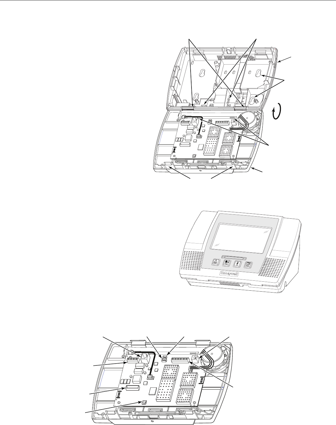
Release the front case from the back case by
depressing the two locking tabs at the top of the unit
with the blade of a medium size screwdriver.
Separate the front and back case assemblies by rotating
the front case so that it is perpendicular to the back
case and unsnapping (releasing) the two hooks from the
back case.
Feed the field wiring through the appropriate openings
in the back case. Use tie-wraps to secure the wiring to
the built-in wire loops as needed.
Mount the back case to a sturdy wall.
Attach the front and back cases by connecting the
hooks on the front case to the attachments on the back
case. Once attached, the hooks will support the front
case and allow you to make the wiring connections.
After all wiring connections have been made, snap the
front case and back case closed and ensure that the case
1.
2.
3.
4.
5.
6.
is secured by the locking tabs.
Desktop Mounting
For desktop mounting, the optional mounting base (model L5000DM, purchased separately) must be used.
5000-100-092-V0
ARMED READY
Slide the control panel onto the mounting base locking
tabs.
Bring all wiring through the bottom of the mounting
base, using one of the wire entry locations, before
making connections to the control panel.
Use tie-wraps to secure the wiring to the built-in wire
loops as needed.
Use the supplied screws to secure the control panel to
the mounting base.
1.
2.
3.
4.
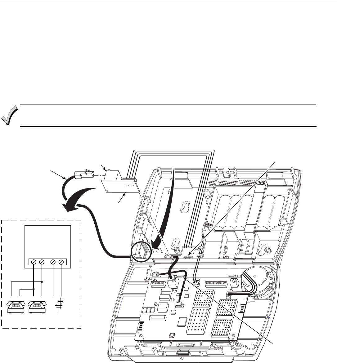
Wiring Overview
The following summarizes the connections required. Refer to the Wiring Connections paragraph and the
Summary of Connections diagram on the inside back cover when making connections.
5000-100-087-V0
TERMINAL
STRIP
TELEPHONE
CONNECTION
TELEPHONE
CONNECTIONS
POWER SUPPLY
RECEPTACLE
STANDARD
CAPACITY BATTERY
CONNECTION
SUPER
HIGH CAPACITY
BATTERY
CONNECTION
TAMPER
SWITCH
GSMVLP5/ILP5
RECEPTACLE
LYNX Touch Installation and Setup Guide
- 7 -
Wiring Connections
FULL LINE SEIZURE CONNECTIONS
RJ31X
1
2
3
45
6
7
8
RING
TIP
INCOMING
PHONE LINE
TO
PREMISES PHONES
INCOMING
PHONE LINE
TO
PREMISES
PHONES
GREENRED
GREY BROWN
RING
TIP
DIRECT
CONNECT
CORD
OR
OR
8-POSITION
JACK
5000-100-094-V1
H/S T
H/S R
RING
TIP
BROWN
GREY
RED
GREEN
Make Earth Ground Connection - The designated earth ground
terminal EGND must be terminated in a good earth ground for the
lightning transient protective devices in this product to be effective.
The following are examples of good earth grounds available at
most installations:
Metal Cold Water Pipe - Secure a non-corrosive metal strap
(copper is recommended) to the pipe that is electrically connected
and secured to which the ground lead is electrically connected and
secured.
AC Power Outlet Ground - Available from 3-prong, 120VAC power
outlets only. To test the integrity of the ground terminal, use a three-
wire circuit tester with neon lamp indicators, such as the UL Listed
Ideal Model 61-035, or equivalent, available at most electrical
supply stores.
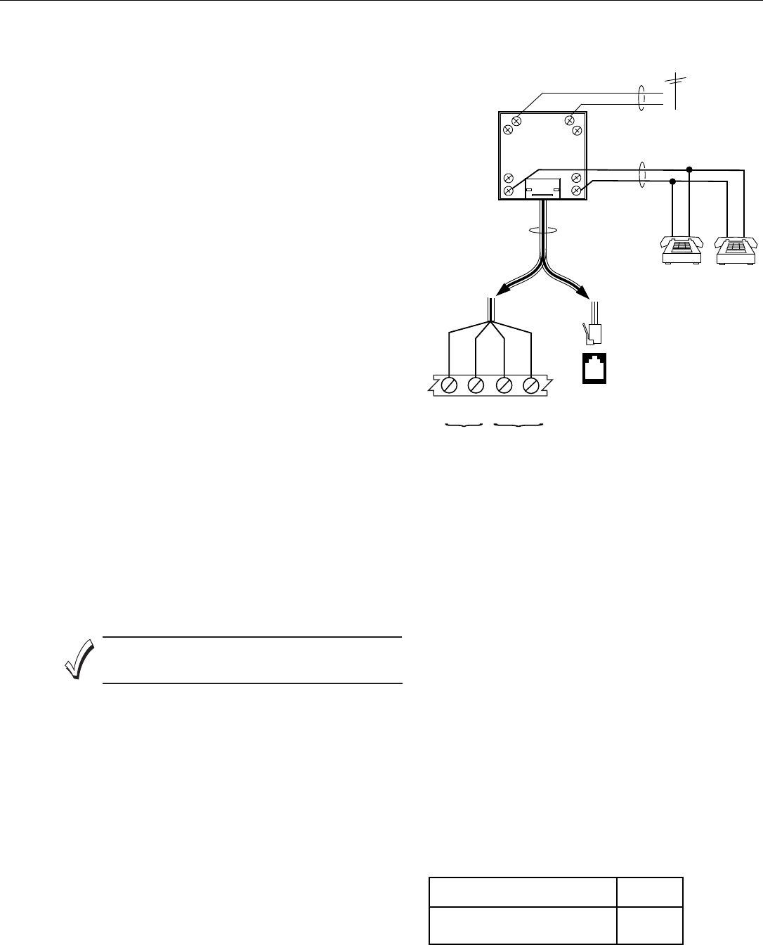
Make Phone Line Connections - For local or full line seizure
follow the appropriate steps below.
Local Seizure
1.
2.
3.
4.
c.
d.
e.
f.
a.
b.
c.
a.
b.
a.
Connect the incoming phone line to either the 8 position jack or
terminals TIP and RING on the LYNX Touch as shown on the
Summary of Connections.
Connect the handset phone lines to terminals H/S T (TIP) and
H/S R (RING) as shown on the Summary of Connections.
terminals as shown in the diagram or plug into the 8-position
Hardwired Zone Connections - One EOLR supervised zone
supports both open circuit and closed circuit devices and has a
response time of 350msec. Maximum zone resistance: 300 ohms,
plus EOLR
Note: The hardwire zone cannot be used as a fire zone.
HARDWIRED ZONE: If the EOLR is not at the end of the
loop, the zone will not be properly supervised, and the
system may not respond to an open circuit on the zone.
Cut the incoming RING and TIP phone lines (typically red and
green, respectively) and connect them to RJ31X terminals 4
(red) and 5 (green).
Connect the premises end of the cut RING and TIP wires to
RJ31X terminals 1 (grey) and 8 (brown) respectively.
Wire the flying leads of a Direct Connect Cord to the control's
phone terminals as shown in the diagram or plug into the 8-
position jack.
Plug the Direct Connect Cord into the RJ31X jack.
Full Line Seizure: The control must be placed in series with the
incoming phone line. Plugging the Direct Connect Cord directly into
the RJ31X jack, allows the control to seize the phone line when an
alarm occurs and normal phone line usage by the premises
phones if the plug needs to be removed.
Connect terminal EGND to a good earth ground as shown on the
Summary of Connections.
Connect sensors/contacts to the hardwired zone terminals GND
(-) and HWZ1 (+). Refer to the Summary of Connections
diagram.
Connect closed circuit devices in series in the high (+) side of
the loop. The EOL resistor must be connected in series with the
devices, following the last device.
Connect open circuit devices in parallel across the loop. The
2000-ohm EOLR must be connected across the loop at the last
device.
AC Power Connections - Connect the Power Supply to the
receptacle on the LYNX Touch.
OR
Connect wires from the Power Supply to +9VDC and EGND
terminals as shown on the summary of connections diagram.
WIRE
GAUGE
DISTANCE BETWEEN
POWER SUPPLY AND CONTROL
Up to 75 feet
75 to 150 feet
# 20
# 18
WIRING TABLE
LYNX Touch Installation and Setup Guide
- 8 -
Wiring Connections
Installing the L5000-RJ31X in the LYNX Touch Control
An auxiliary L5000-RJ31X receptacle can be installed in the LYNX Touch that will allow the telephone cable
to be disconnected without requiring the unit to be opened up.
1. Using a wire cutter or knife cut the plastic tabs that secure the receptacle knockout from the left side of the LYNX Touch back case.
2. Connect four wires between the L5000-RJ31X receptacle terminal strip and the incoming phone line and the premises telephones
as shown on the figure below.
3. Install the L5000-RJ31X receptacle into the slot on the back case.
4. Connect one end of the L5000-RJ31X cable to the 8-position jack on the LYNX Touch PC board.
5. Route the cable through the opening in the back case and along the wire channel in the back case.
6. Connect the other end of the cable to the L5000-RJ31X receptacle on the side of the back case as shown below.
7. Secure the wires to the tie wrap points on LYNX Touch front and back case with the provided tie wraps.
To allow flush wall or desk mounting of the control, ensure that L5000-RJ31X cable is routed through the
channel in the case back. Ensure enough slack is left in the wires to allow the case to close without pinching
the wires.
5000-100-155-V1
INCOMING / PREMISES TELEPHONE WIRING
REMOVE
KNOCKOUT
TIE WRAP
POINT
TIE WRAP
POINT
L5000-RJ31X
CABLE
L5000-RJ31X
REFER TO
WIRING
SCHEMATIC
FOR
CONNECTIONS
L5000-RJ31X
TERMINAL STRIP
RING
TIP
HS TIP
HS RING
INCOMING
PHONE LINE
TO PREMISES
TELEPHONES
L5000-RJ31X WIRING
LYNX Touch Installation and Setup Guide
- 9 -
AC Power and Backup Battery
The system is powered by a 9 Volt DC, 2.7 Amp Plug-in Power Supply, 300-04705 or 300-04065 (300-04063
in Canada). Refer to the wiring table below for wire gauge and length. In the event of an AC power loss, the
system is supported by a long life backup battery that is supervised for connection and for low voltage
conditions. If the battery is missing, or a low battery condition is detected, a “low battery” message is
displayed and a report is sent to the central station. In addition, the system will beep once every 45 seconds
to audibly indicate a low battery condition (press any key to stop the beeping).
Use only the provided 300-04705 or 300-04065 (300-04063 Canada) Power Supply. Wiring to the Power
Supply must not exceed 300 feet using 16-gauge wire.
Do not plug the power supply into the AC outlet until after all wiring connections have been made. Ensure the
cover is snapped closed prior to applying AC power
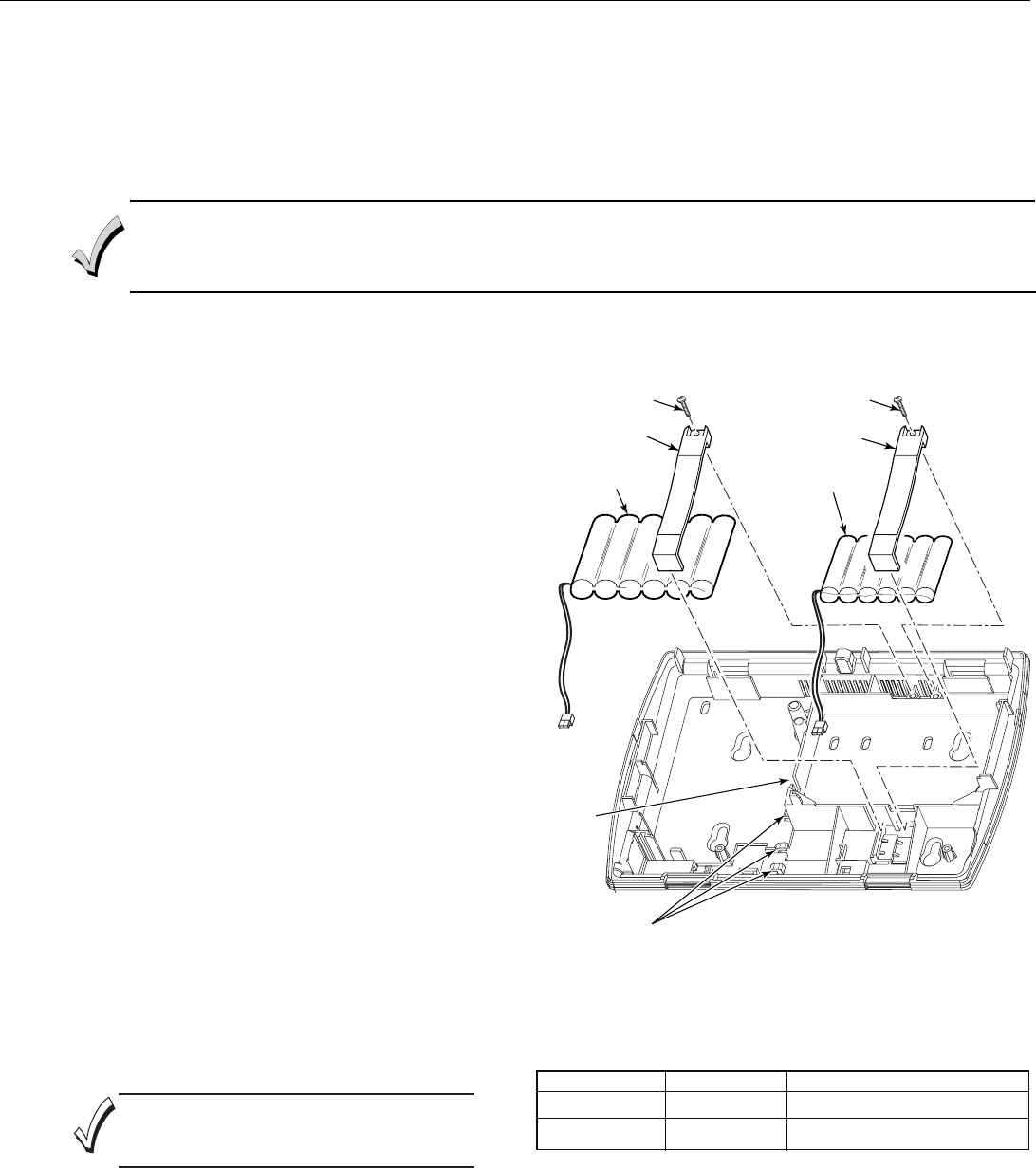
The LYNX Touch is equipped with an integral, replaceable, rechargeable battery pack rated at 7.2Vdc.
Select the appropriate battery pack, based on the installation’s requirement, and install the battery pack.
5000-100-093-V0
OR
RETAINER
SCREW
RETAINER
SCREW
Remove battery retainer.
Insert battery pack into back case.
Route cable through channel (cutout) on left side of
compartment.
Install battery retainer.
Secure battery retainer with the provided screw.
Secure battery wiring in the wire routing clips (3).
Connect the battery connector to the receptacle on the PC
board.
After the wiring connection has been made, snap the front
and the back case closed.
Plug the power supply into a 24-hour, 110VAC unswitched
outlet. Upon powerup, the system will display "Please Wait
Checking System Integrity".
When battery replacement is required, unplug the
transformer from the wall outlet, and open the control panel
cover.
Remove the screw that secures the battery retainer.
Remove the battery retainer and disconnect the battery
pack connector from the receptacle on the PC Board.
Remove the battery pack from the back case.
Install a replacement battery pack (P/N 300-03864-1/
LYNXRCHKIT-SC or P/N 300-03866/LYNXCHKIT-SHA)
into the back case.
Route cable through channel (cutout) on left side of
compartment.
Install the battery retainer.
Secure battery retainer with the provided screw.
Secure battery wiring in the wire routing clips (3).
Connect the battery connector to the receptacle on the PC
board.
After the wiring connection has been made, snap the front
and the back case closed.
Plug the power supply into a 24-hour, 110VAC unswitched
outlet. Upon powerup, the system will display "Please Wait
Checking System Integrity".
Battery Selection
The LYNX Touch is equipped with an integral, replaceable, rechargeable
battery pack rated at 7.2Vdc. Select the appropriate battery pack,
based on the installation's requirement, and install the battery pack.
Battery Part Number Battery StandbyTime Low Battery Notification
300-03866/
LYNXRCHKIT-SHA
300-03864-1/
LYNXRCHKIT-SC 4-hours (minimum) Approximately 1-hour before battery depletion
mfr24-hours (mini um) At least 1-hour be ore batte y depletion
Installing the Rechargeable Backup Battery
Replacing the Rechargeable Backup Battery
1.
2.
3.
4.
5.
6.
7.
8.
9.
1.
2.
3.
4.
5.
6.
7.
8.
9.
10.
11.
BATTERY
CABLE
CHANNEL
BATTERY
WIRE ROUTING
CLIPS (3)
Ensure the control panel assembly is snapped closed
prior to applying AC power. Rechargeable batteries may
take up to 48-hours to fully charge. The "Low Battery"
message should clear within four hours or by entering an
OFF sequence.
BATTERY PACK
(P/N 300-03866/
LYNXRCHKIT-SHA)
BATTERY PACK
(P/N 300-03864-1/
LYNXRCHKIT-SC)
LYNX Touch Installation and Setup Guide
- 10 -
Installing/Configuring Communication Modules
General
This LYNX Touch control supports central station reporting using wireless (GSM) and hardwire (IP)
communications modules. It also supports upload/download programming capability via the Internet or a
Private local area network (Intranet). This allows site maintenance independent of central station
monitoring, and modification to sites globally via the Internet or through a private LAN. Refer to the
instructions provided with the LRR/IP Communications Module being installed for additional information
regarding its installation, programming, and registration. The control is compatible with the following
AlarmNet Communications Modules:
• GSMVLP5 GSM Communication Module
• ILP5 Ethernet Communications Module
Communications Module 24-Hour Standby Power
If you require 24-hour standby, you must install the Super High Capacity battery P/N LYNX-RCHB-SHA in
the control.
RF Exposure
WARNING: The LYNX Touch must be installed to provide a separation distance of at least 7.8 in (20 cm)
from all persons and not co-located or operated in conjunction with any other transmitter.
Connecting and Configuring Communication Modules
Connect and configure the communications module as follows:
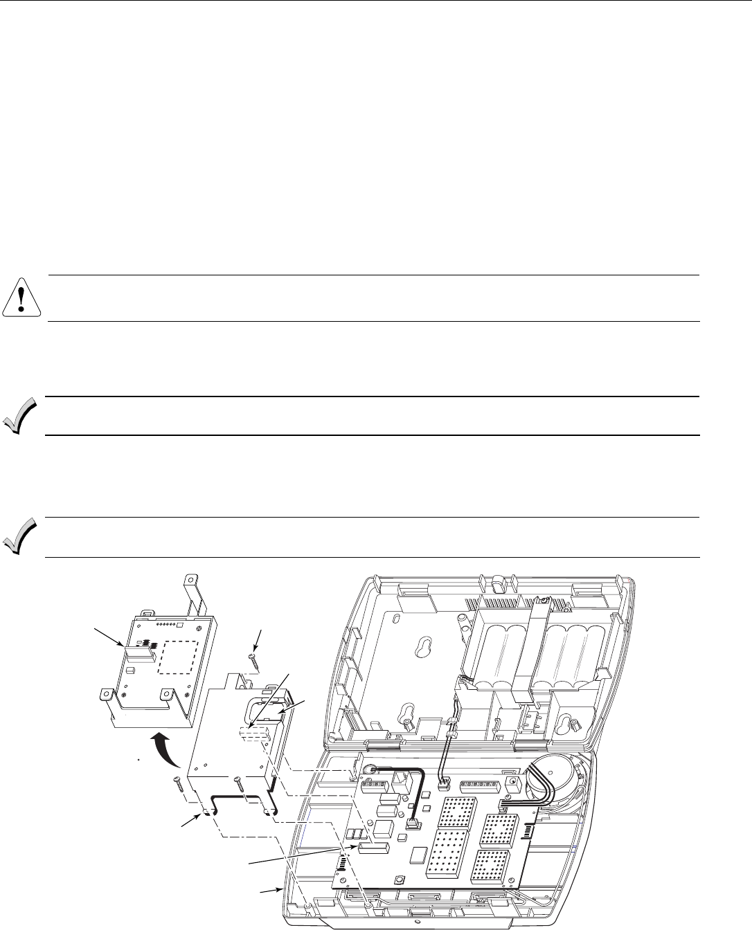
Installing the GSMVLP5 in the LYNX Touch Control
Ensure that SIM card and the connector board are securely installed in the GSMVLP5 before installing the
communications module in the LYNX Touch.
1. Install the GSMVLP5 into the LYNX Touch control front case. Ensure that the connector board is properly seated into the receptacle on
the control.
2. Secure the GSMVLP5 with the three provided screws.
3. Enable the GSMVLP5 device, configure alarm reporting and module supervision and register the device. Refer to the “Program the
Communications Module” and “Communications Diagnostics” sections.
The communications module must be registered with AlarmNet before downloading or alarm reporting can
take place.
SCREW
3
SIM
CARD
5000-100-151-V0
ROTATED
180
CONNECTOR
BOARD
CONNECTOR
BOARD
RECEPTACLE
GSMVLP5
LYNX TOUCH
LYNX Touch Installation and Setup Guide
- 11 -
Installing/Configuring Communication Modules
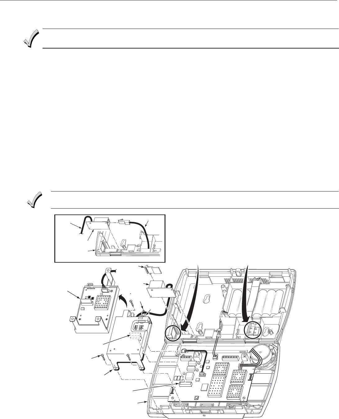
Installing the ILP5 in the LYNX Touch Control
Ensure that the connector board and cable are securely installed in the ILP5 before installing the
communications module in the LYNX Touch.
1. Using a wire cutter or knife cut the plastic tabs that secure the ILP5 spacer from to the back case of the LYNX Touch.
2. Remove the ILP5 receptacle knockout from the left side of the LYNX Touch back case.
3. Install the ILP5 into the LYNX Touch control front case. Ensure that the connector board is properly seated into the receptacle on the
control.
4. Secure the ILP5 with the three provided screws.
5. Insert the ILP5 receptacle and spacer into the slot on the back case.
6. Secure the communications cable to the tie wrap point on the ILP5 with the provided tie wrap.
7. Connect the Ethernet cable to the RJ45 receptacle.
8. Enable the ILP5 and configure alarm reporting and module supervision and register the device. Refer to the “Program the
Communications Module” and “Communications Diagnostics” sections.
Alternate Installation (Refer to the Alternate Installation as shown on the figure below)
1. Install the ILP5 into the LYNX Touch control front case. Ensure that the connector board is properly seated into the receptacle on the
control.
2. Secure the ILP5 with the three provided screws.
3. Insert the ILP5 receptacle into the slot on the back case as shown on the figure below.
4. Secure the communications cable to the tie wrap point on the ILP5 with the provided tie wrap.
5. Connect the Ethernet cable to the RJ45 receptacle.
6. Enable the ILP5 and configure alarm reporting and module supervision and register the device. Refer to the “Program the
Communications Module” and “Communications “Diagnostics” sections.
The communications module must be registered with AlarmNet before downloading or alarm reporting
can take place.
SCREW
(3)
5000-100-154-V0
ROTATED
180
CONNECTOR
BOARD
CONNECTOR BOARD
RECEPTACLE
ILP5
LYNX TOUCH
TIE
WRAP
POINT
REMOVE ILP5
SPACER
ILP5 SPACER
REMOVE ILP5
KNOCKOUT
TIE
WRAP
(1)
TO ILP5
LYNX TOUCH
ALTERNATE INSTALLATION
RJ45
RECEPTACLE
RJ45 RECEPTACLE
ETHERNET CABLE
LYNX Touch Installation and Setup Guide
- 12 -
Installing Wireless Zones
General Information
Zones
The control supports up to 64 total wireless zones using 5800 Series transmitters, and wireless buttons.
Range
The built-in RF receiver can detect signals from wireless transmitters within a nominal range of 200 feet.
Transmitters
5800 Series transmitters have built-in serial numbers that must be entered into the system using the
“Zones” programming section, or input to the control via the downloader. 5800 Series transmitters (except
the 5800RL) do not have DIP switches. Each transmitter's zone number is also programmed into the system
in the “Zones” programming section. Some transmitters, such as the 5816 and 5817, can support more than
one "zone" (referred to as loops or inputs). On the 5816, for example, the wire connection terminal block is
loop 1; the reed contact is loop 2. Each loop must be assigned a different zone number.
For button transmitters (RF "keys") such as the 5804, you must assign a unique zone number to each
individual button used on the transmitter. Each button on the transmitter also has a pre-designated loop
or input number, which is automatically displayed.
UL
The 5816 and 5817 Transmitters do not have EOL supervision of their loop wiring, which must not exceed 3 feet.
The 5800RL, 5802MN, 5802MN2, 5804, 5804BD, 5804BDV, 5804E, 5814, 5816TEMP, 5819, 5819S(WHS & BRS), 5828/5828V
and 5850(GBD) transmitters have not been evaluated by UL.
House Identification
If you are using a 5804BD/5804BDV Wireless Keypad with the system, you must program a House ID Code
(01–31) as described in the “SYSTEM TYPE” programming section to establish proper communication, and
the keypad must be set to the same ID. House ID 00 disables all wireless keypads. An RF House ID is not
necessary for other 5800 Series transmitters; the entry should be left at “00” (default) in those cases.
Transmitter Supervision
With the exception of some transmitters/keypads that may be carried off-premises (5804, 5804BD,
5804BDV, 5804E and 5805-6), each transmitter is supervised by a check-in signal that is sent to the
receiver at 70–90 minute intervals. If at least one check-in is not received from each supervised transmitter
within a 12-hour period, the "missing" transmitter zone number(s) and "Supervision" will be displayed. The
supervision for a particular transmitter in the system that may also be carried off the premises
(5802/5802MN2, 5802MN) may be turned off by entering it as a Unsupervised RF (UR) type, as described in
the “ZONES” programming section. 5800 Series transmitters have built-in tamper protection and will
annunciate as a fault condition if covers are removed.
Transmitter Input Types
Each of the transmitters has one or more unique factory-assigned input (loop) ID codes. Each of the inputs
requires a programming zone (e.g., a 5804's four inputs require four button zones). Transmitters can be entered
as one of the following types (see transmitter’s instructions for appropriate input type):
Type Description
Supervised RF ("RF") Sends periodic check-in signals, as well as fault, restore, and low battery signals. The
transmitter must remain within the receiver's range.
Unsupervised RF ("UR") Sends all the signals that the "RF" type does, but the control does not supervise the check-in
signals. The transmitter may therefore be carried off-premises.
Unsupervised Button RF ("BR") Sends only fault signals. They do not send low battery signals until they are activated. The
transmitter may be carried off-premises.
Transmitter Battery Life
• Batteries in the wireless transmitters may last from 4–7 years, depending on the environment, usage,
and the specific wireless device being used. Factors such as humidity, high or low temperatures, as well
as large swings in temperature may all reduce the actual battery life in a given installation. The wireless
system can identify a true low battery situation, thus allowing the dealer or user of the system time to
arrange a change of battery and maintain protection for that point within the system.
• Button-type transmitters should be periodically tested for battery life. The 5802MN, 5802MN2, 5804,
5804BD, 5804BDV, and 5804E button transmitters have replaceable batteries.
LYNX Touch Installation and Setup Guide
- 13 -
Installing Wireless Zones
RF Sniffer Test Mode
This mode is used after all transmitters have been entered to check that all transmitters have been
properly programmed. Sniffer mode does not automatically expire. You must manually exit Sniffer mode by
selecting Off and entering the Installer Code to return to normal operation.
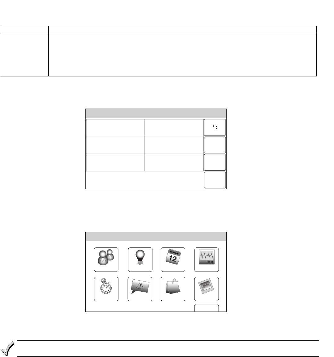
SCREEN ACTION
5000-100-096-V0
Test
1. At the Tools Screen, select “Test”. The following options are displayed.
Walk Test
Go-No-Go Test
RF Sniffer Test
Dialer Test
5000-100-102-V0
RF Sniffer
Test
2. Select “RF Sniffer Test” from the options.
Note: If the communicator is in the process of sending a report to the central station, the
system will not go into the Sniffer mode. If so, wait a few minutes and try again.
3. The system displays all programmed zone numbers and zone descriptors, which have a
non-zero Zone Type. Fault each transmitter in turn, causing each one to send a signal. As
the system receives a signal from each of the transmitters, the zone number of that
transmitter disappears from the display. The transmitters may be checked upon installation,
or in an installed system. The system will beep once every 30-40 seconds while the RF
Sniffer Test mode is active.
4. When all transmitters have been checked, Exit RF Sniffer Test mode by depressing the Off
key and entering the Installer or a User Code.
Notes: (1) All button-type (BR) units must physically be activated to clear the display, since they do not automatically send
check-in signals.
(2) When one button of a button type, supervised or unsupervised RF transmitter (RF, UR, or BR) is activated, all zones assigned
to other buttons on that transmitter are cleared. This also applies to 5816 and 5817 transmitters that have multiple loops
(zones).
(3) Any transmitter that is not “entered” will not turn off its zone number.
(4) For SIA installations, the following devices may be used as specified for panic (24-hour) alarm response:
• wireless keys which have two-button panic pairs available (e.g., 5804BDV), on which only the two-button panic pairs may
be programmed for any 24-hour alarm response
• wireless keypads (e.g., 5828/5828V) keypads that have a two-second delay on the special function keys, or two-button panic
pairs
• built-in keypad panic key
Go/No Go Test Mode
Conducting this test with your hand wrapped around the transmitter will cause inaccurate results.
On button type transmitters that have been programmed to set ARM AWAY, ARM STAY, or DISARM, pressing a
button will take the system out of the Go/No Go Test mode causing the programmed action to occur.
The Go/No Go tests will verify adequate RF signal strength from the proposed transmitter location, and
allow you to reorient or relocate transmitters if necessary, before mounting the transmitters permanently.
This mode is similar to the transmitter Test mode, except that the wireless receiver gain is reduced. This
will enable you to make sure that the RF signal from each transmitter is received with sufficient signal
amplitude when the system is in the normal operating mode.
SCREEN ACTION
5000-100-096-V0
Test
1. At the Tools Screen, select “Test”. The following options are displayed.
Walk Test
Go-No-Go Test
RF Sniffer Test
Dialer Test
5000-100-103-V0
Go-No-Go
Test
2. Select “Go-No-Go Test”.
3. Once you have placed transmitters in their desired locations, and the approximate length of
wire to be run to sensors is connected to the transmitter's screw terminals (if used), fault
each transmitter.
a. The keypad beeps three times indicating signal reception, displays the appropriate
zone number and announced the zone description.
b. If the keypad does not beep, reorient or move the transmitter to another location.
Usually a few inches in either direction is all that is required.
4. If each transmitter produces the proper keypad response when faulted, they can be
permanently mounted according to their respective instructions.
5. The system will beep once every 30-40 seconds while the Go-No-Go Test mode is active.
6. Exit Go-No-Go Test mode by depressing the Off key and entering the Installer or a User
Code.
LYNX Touch Installation and Setup Guide
- 14 -
Installing Wireless Zones
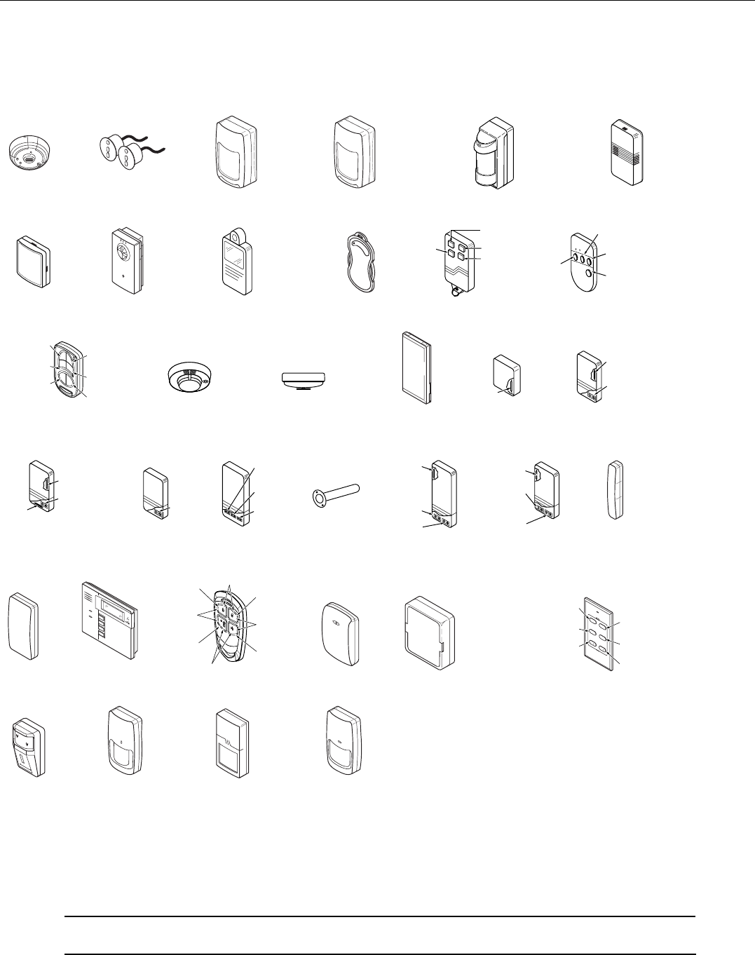
5800 Series Transmitter Loop Numbers
(Refer to this information when programming transmitters)
The following illustration shows the compatible transmitters, their associated input types and loop
designations.
LOOP 1
5806/5806W3/5807
5808/5808LST/5808W3
ENROLL AS
"RF"
LOOP 1LOOP 1
5809
ENROLL AS
"RF"
5818
ENROLL AS
"RF"
LOOP 1
LOOP 1
LOOPS
1 - 3
LOOP 1
LOOP 1
LOOP 1LOOP 1
5814
ENROLL
AS
"RF"
5800-002-V0
LOOP 1
(MOTION)
5897
ENROLL AS
"RF"
5890/5890PI
ENROLL AS
"RF"
LOOP 1LOOP 1
5802MN
ENROLL AS
"UR" OR "RF"
5805-6
ENROLL AS
"BR"
5804BD/5804BDV
ENROLL AS
"BR"
PROGRAM HOUSE ID
LOOP 4
LOOP
3LOOP 1
LOOP 2
•
•
••
•
•
•
•
•
•
•
•
•
•
•
•
•••
5804/5804E
ENROLL AS "BR"
5816TEMP
ENROLL AS
"RF"
LOOP 1
(TEMP
SENSOR)
5817
ENROLL AS
"RF"
LOOP 2
(AUX.
CENTER)
LOOP 1
(PRIMARY)
LOOP 3
(AUX.
RIGHT)
5816
ENROLL AS
"RF"
LOOP 1
(TERMINALS)
LOOP 2
(REED)
5816MN
ENROLL AS
"RF"
LOOP 1
(TERMINALS)
ALTERNATE
POSITION
FOR LOOP 2
LOOP 2
(REED) LOOP 3
(TERMINALS)
5828/5828V
PROGRAM
HOUSE ID
5821
ENROLL AS
"RF"
5820L
ENROLL AS
"RF"
5819S (WHS & BRS)
ENROLL AS
"RF"
LOOP 1
(INTERNAL
SHOCK
SENSOR
LOOP 2
(REED)
5819
ENROLL AS
"RF"
LOOP 2
(REED)
LOOP 3
(TERMINALS)
LOOP 1
(TERMINALS)
5800WAVE
PROGRAM
HOUSE ID
5800PIR-OD
ENROLL AS "RF"
5800PIR/
5800PIR-COM
ENROLL AS "RF"
5811
ENROLL AS "RF"
5800PIR-RES
ENROLL AS "RF"
5800Micra
ENROLL AS "RF"
5800CO
ENROLL AS "RF"
5800SS1
ENROLL AS "RF"
5800RL
SET
HOUSE ID
LOOP 1
LOOP 1
(LOW
SENSITIVITY
LOOP 2
(HIGH
SENSITIVITY)
LOOP 3 (TEMP)
LOOP 4 (TAMPER)
LOOP 1
(HIGH
SECURITY)
LOOP 2
(STANDARD
SECURITY)
LOOP 3 (TILT MODE)
LOOP 4 (TAMPER)
LOOP 1
(LOW
SENSITIVITY
LOOP 2
(HIGH
SENSITIVITY)
LOOP 3 (TEMP)
LOOP 4 (TAMPER)
5834-4
ENROLL AS "BR"
5894PI
ENROLL AS
"RF"
5802MN2
ENROLL AS
"UR" OR "RF"
LOOP
1
LOOP
1LOOP
1
LOOP
1
5878
ENROLL AS
"BR"
5870API
ENROLL AS
"RF"
5853
ENROLL AS
"RF"
ARMED
READY
LOOP 1
(LOW SENSITIVITY)
LOOP 2
(HIGH SENSITIVITY)
5898
ENROLL AS
"RF"
LOOP 4
LOOP 1
LOOP 2
LOOP 3
SERIAL #1
LOOP 3
SERIAL #1
LOOP 4
SERIAL #2
LOOP 3
SERIAL #1
LOOP 2
SERIAL #1
LOOP 1
SERIAL #2
LOOP 2
3
AWAY STAY
12
4
OFF
ON
43
21
OFFON
SERIAL #1
LOOP 3
SERIAL #1
LOOP 4
SERIAL #2
LOOP 1
SERIAL #2
LOOP 2
SERIAL #2
LOOP 3
SERIAL #1
LOOP 2
SERIAL #1
LOOP 1
SERIAL #1
LOOP 3
SERIAL #1
LOOP 4
SERIAL #2
LOOP 3
SERIAL #1
LOOP 2
SERIAL #1
LOOP 1
SERIAL #2
LOOP 2
SERIAL #2 - LOOP 1 = ON + 4 BUTTONS
LOOP 4 = 3 + 4 BUTTONS
SERIAL #2
LOOP 4
Notes: (1) The 5806W3 smoke detector must be used in SIA applications.
(2) Button type (BR) devices send only fault and low battery signals; no restore or check-in signals.
Supervised RF (RF) devices send periodic check-in signals, faults, restore and low battery signals.
Unsupervised RF (UR) devices send periodic check-in signals, faults, restore and low battery signals but the
control does not supervise the check-in signals.
(3) If an external sounder is required, the 5800WAVE should be used.
UL The 5800RL, 5802MN, 5802MN2, 5804, 5804BD, 5804BDV, 5814, 5816TEMP, 5819, 5819S(WHS & BRS), and
5828/5828V wireless transmitters have not been evaluated by UL.
LYNX Touch Installation and Setup Guide
- 15 -
Mechanics of Programming
Navigating Menus
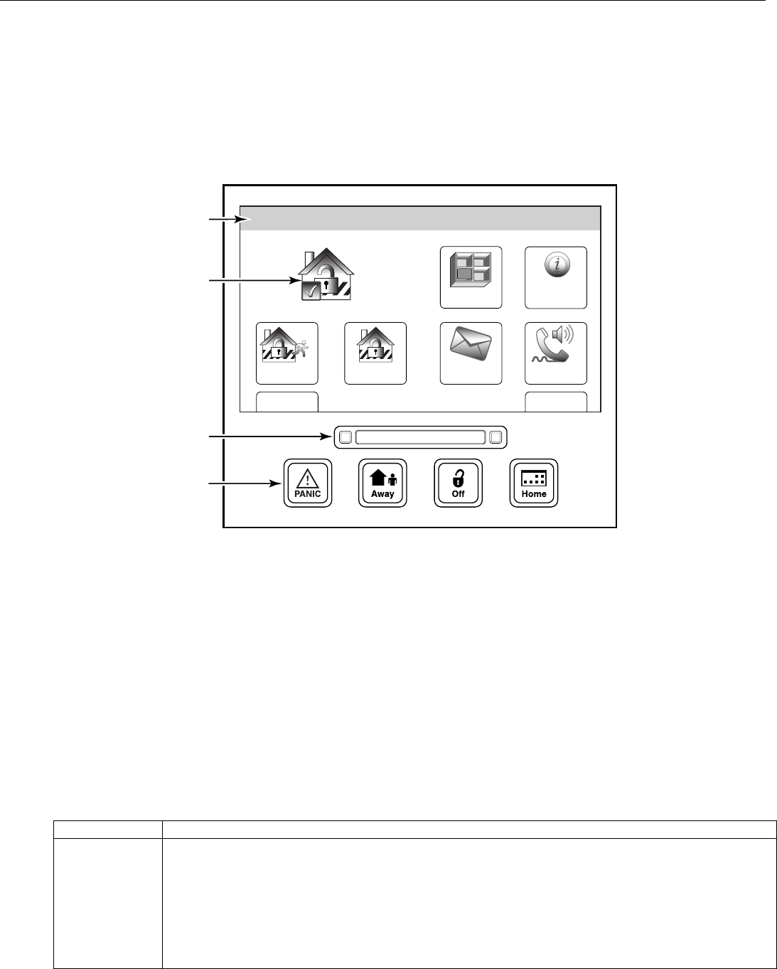
Touch-screen Display
LYNX Touch’s Liquid Crystal Display (LCD) touch-screen displays variable icons and text on “screens”. The
screen displays status icons and associated text, the current time, system status information and menu
choices. The Menu area includes a list of commands, or choices that apply to the current selection. The
status area provides information about various system events and a colored bar also provides an indication
of system status. A “Home Screen” is displayed whenever power is applied to the system. In addition the
green “READY” LED is lit when the system is ready or flashes when it is not.
Zones
Arm Away
Ready To Arm
Arm Stay
MoreDelay
Phone
10:18 AM June 8, 2010
5000-100-054-V0
Message
System
ARMED READY
SYSTEM
STATUS
SYSTEM/ZONE
STATUS
FUNCTION
KEYS
LEDs
Home Screen (page 1)
Navigation Keys
Navigating through the screens is accomplished by lightly touching the menu item on the touch-screen.
Once activated, the control will take you to the next screen. Selecting the “Home” (cancel) key or the “2”
Key will return you to the previous screen at any time unless System Programming mode is active. By
Touching (selecting) an icon or key the system, depending on the function, advances to another screen,
toggles between options or scrolls through multiple options that can be selected. The system provides a
prompt when a specific input is required.
Note: You may find it convenient to adjust the volume setting before entering the Program Mode. This will allow you to clearly hear
the feedback announcements or system beeps from the system’s built-in speaker. To adjust the volume, select “More” on the
“home Screen” and then select “Settings”. Adjust the volume using the slide displayed on the Settings screen and then select
“Save” to accept. Upon exiting the Program Mode, the system resets the volume to the default value (mid level).
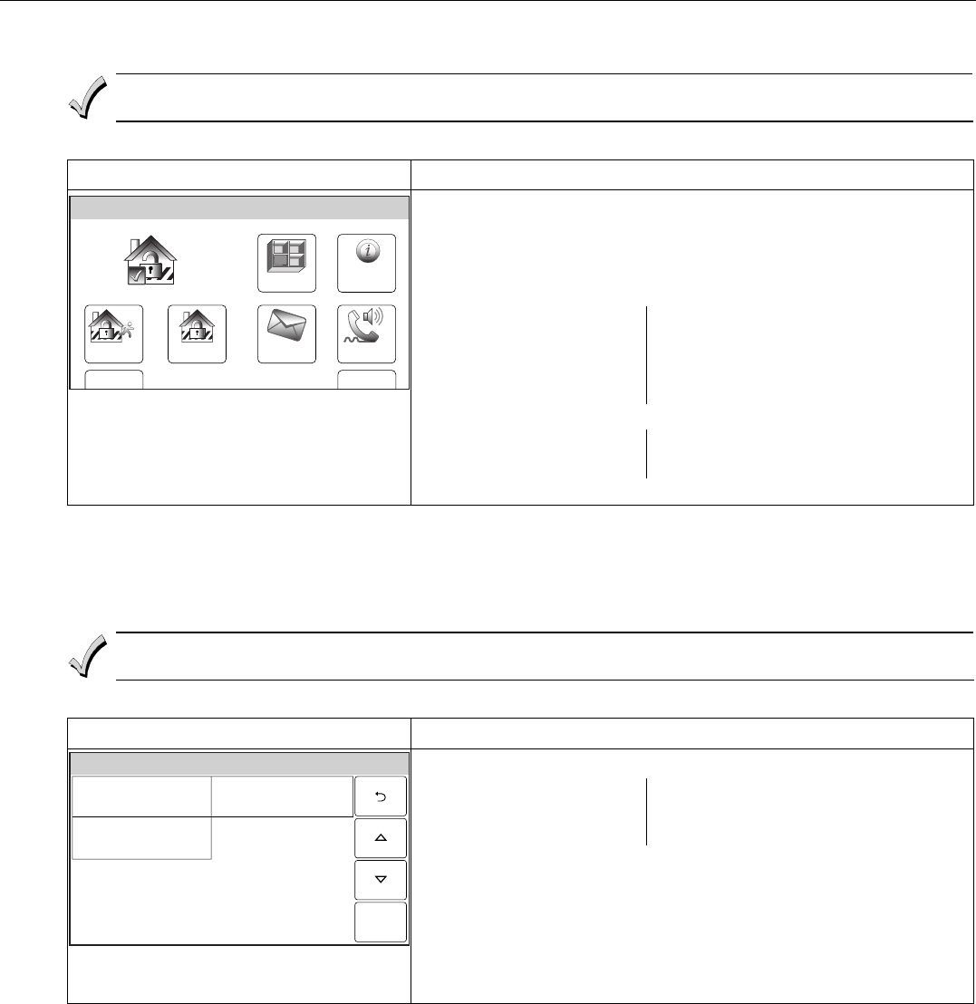
Menu Screens
System Status is displayed at the top of each screen. The time and date are displayed at the bottom of the
Home Screen. The Home Screen consists of two pages. The first page displays the system status and eight
selection “buttons” and “tabs”.
Selection Function
Zones Provides access to Zone information and options.
System Provides information about system status
Arm Away Used to Arm the system in Away mode (displayed on both Home Screen pages).
Arm Stay Used to Arm the system in Stay mode (displayed on both Home Screen pages).
Message Provides access to Message Center.
Phone Provides access to Speaker Phone mode. (if programmed)
Delay/Instant Used to toggle between exit delay and instant arming options (displayed on Home Screen pages).
More Advances system to second page of the Home Screen.
LYNX Touch Installation and Setup Guide
- 16 -
Mechanics of Programming
The second page also displays the system status in and six selection “buttons” and “tabs”.
Selection Function
Tools Provides access to Installer and User Programming Menus (Master User Code required for access).
Arm Away Used to Arm the system in Away mode (displayed on both Home Screen pages).
Arm Stay Used to Arm the system in Stay mode (displayed on both Home Screen pages).
Settings Provides access to various keypad functions (i.e.; Brightness, Contrast, Volume, Voice, Chime & Ringer).
Delay/Instant Used to toggle between exit delay and instant arming options (displayed on both Home Screen pages).
Back Returns system to first page of the Home Screen.
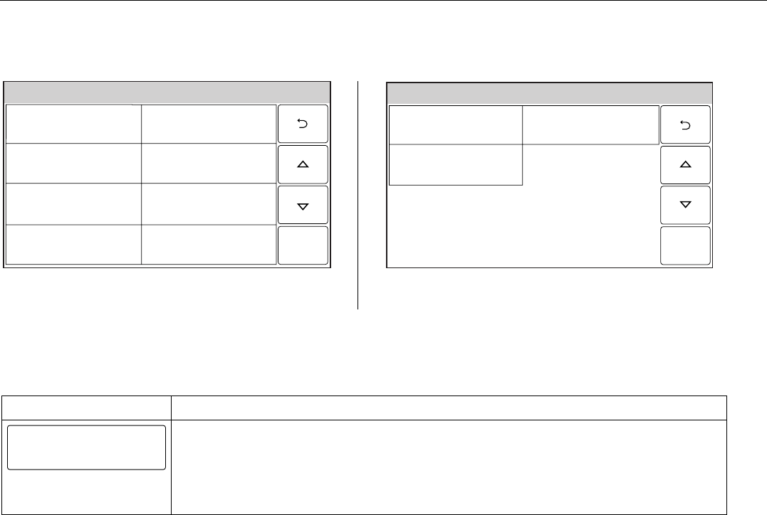
Installer Tools Menu
The Tools/Installer Menu provides access to the Installer configurable features and displays six options.
Entering the Installer Code is required to access the Installer Menu.
Ready To Arm
5000-100-043-V0
Program
Events
Schedules
Test
Initiate
Download
Devices
Installer Menu Page
User Tools Menu
The User Menu provides access to the User configurable features and displays eight options. Entering the
Master User Code is required to access the User Menu.
Slide ShowDate Time
Ready To Arm
Events
Back
Reminders
TestSchedulesDevicesUsers
5000-100-070-V0
User Menu Page
General Programming Information
When power cycling the control, remove AC power first and wait approximately 1 minute before
disconnecting battery.
Programming options are stored in non-removable, electrically erasable, nonvolatile EEROM memory. The
system can be programmed at any time, even at the installer's premises prior to the actual installation.
Simply apply power temporarily to the Control and then program the unit as desired.
The system can also be programmed remotely, using an IBM PC compatible Personal Computer, and
Compass Downloader and modem or via capable GSM or IP communications modules. See the Remote
Programming/Control (Downloading) section.
LYNX Touch Installation and Setup Guide
- 17 -
Mechanics of Programming
Programming
If the system is Armed or in Alarm, the Tools icon will not be functional. The system must first be
disarmed.
To enter Installer Programming Mode:
SCREEN ACTION
Zones
Arm Away
Ready To Arm
Arm Stay
MoreDelay
Phone
10:18 AM June 8, 2010
5000-100-006-V0
Message
System
1. At the Home Screen select “More”.
2. Select “Tools”. The system displays a virtual keypad.
3. Enter the Installer Code 4112.
4. The System Programming Screen is displayed. Select “Program” to
display the following options:
Installer Code
Date Time
Zones
Keys
System Type
Communications
Comm. Diagnostics
Reporter
Use the down T arrow to scroll to the next page of options.
Sounder
Default Config.
System Settings
5. Selecting an option advances to that Programming screen.
Loading Factory Defaults
To load the factory defaults, enter the Installer Programming Mode and advance to second page of the
System Programming and refer to following procedure. Refer to the Programming Default Tables section of this
manual to view the Default Tables.
If a default table is loaded, any data that has already been programmed into the system will be changed
according to the default table selected!
To Select a Default Configuration
SCREEN ACTION
System Programming...
5000-100-035-V0
System SettingsSounder
Default Config.
1. Select “Default Configuration” to display the following options:
Default Config 1
Default Config 3
Default Downloader
Default Config 2
Default Config 4
Note: For a list of the pre-programmed defaults refer to the Default Tables
section.
2. Select the desired Default Configuration.
3. A Confirmation screen is displayed.
4. If “Yes” is selected, the System beeps three times and returns to the
Default option screen.
5. If “No” is selected, the System returns to the Default option screen.
Exiting Program Mode
1. Select the “2” key to exit the current screen. The system returns to the previous screen.
2. Select the “2” key as required until system displays a Confirmation screen.
3. Select “Yes” to allow the installer to re-enter Programming mode or “No” to prevent re-entry. If “No” is
selected, you can still re-enter Program Mode by powering down the unit (remove AC and battery
power) and entering Program Mode within 30 seconds of powering up.
4. Select the “2” key again to return to the Home Screen.

LYNX Touch Installation and Setup Guide
- 18 -
Zone Response Type Definitions
General Information
During programming, you must assign a zone type to each zone, which defines the way in which the system
responds to faults in that zone. Zone types are defined below.
Type Function Characteristics
Not Used Used to program a zone that is not used. • None
Entry/Exit 1
(Burglary)
Usually assigned to sensors or contacts on
primary entry and exit doors.
• Entry delay #1 is programmable.
• Exit delay is independently programmable.
• Exit and entry delays when armed in AWAY or STAY mode.
• No entry delay when armed in STAY INSTANT or AWAY
INSTANT mode.
• Exit delay regardless of the arming mode selected.
Entry/Exit 2
(Burglary)
Usually assigned to sensors or contacts on
secondary entry and exit doors that might be
further from the keypad (typically used for a
garage, loading dock, or basement door).
• Entry delay #2 is programmable.
• Exit delay is independently programmable.
• Secondary entry delay, if armed in the AWAY or STAY mode.
• No entry delay when armed in the STAY INSTANT or AWAY
INSTANT mode.
• Exit delay begins regardless of the arming mode selected.
Perimeter
(Burglary)
Usually assigned to all sensors or contacts on
exterior doors and windows
• Instant alarm, when armed in AWAY, STAY, STAY NO DELAY,
or AWAY INSTANT mode.
Interior, Follower
Usually assigned to a zone covering an entry
area (i.e.: foyer, lobby, or hallway) that one
must pass upon entry (after faulting the
entry/exit zone) to reach the keypad. It provides
an instant alarm if the entry/exit zone is not
violated first, and protects an area in the event
an intruder has hidden on the premises before
the system is armed, or gains access to the
premises through an unprotected area.
• Delayed alarm (using the programmed entry/exit time) if
entry/exit (types 01 or 02) or interior-with-delay (type 10) zone is
faulted first.
• Instant alarm in all other situations.
• Active when armed in AWAY or AWAY INSTANT mode.
• Bypassed automatically when armed in STAY or STAY
INSTANT mode.
Trouble by Day/
Alarm by Night
Usually assigned to a zone that covers a
sensitive area (i.e.: stock room, drug supply
room, etc.) It can also be used on a sensor or
contact in an area where immediate notification
of an entry is desired.
• Instant alarm, when armed in AWAY, STAY, STAY INSTANT, or
AWAY INSTANT (night) mode.
• Provides a latched trouble sounding from the keypad and, if
desired, a central station report when disarmed (day).
24-hour Silent
Alarm
Usually assigned to a zone containing an
Emergency button (silent emergency).
• Sends a report to the central station but provides no keypad
display or sounding.
• In disarmed state sends a report to the central station displays
"Not Ready to Arm" on the keypad and “AWAY”, “STAY” and
“TOOLS” buttons are disabled.
24-hour Audible
Alarm
Usually assigned to a zone containing an
Emergency button (audible emergency).
• Follows sounder timeout
• Sends a report to the central station, and provides alarm sounds
at the keypad.
24-hour
Auxiliary Alarm
Usually assigned to a zone containing a
button for use in personal emergencies or to
a zone containing monitoring devices (i.e.:
water or temperature sensors, etc.).
• Sends a report to the central station and provides an alarm
sound at the keypad. (There is no keypad timeout.)
Fire No
Verification
Can be assigned to any wireless zone used as
a fire zone. This zone type is always active and
cannot be bypassed.
• Alarm sound will pulse when this zone type is alarmed.
Interior with Delay
Bypassed when the panel is armed in the STAY
or STAY INSTANT mode.
• Entry delay #1 (with programmed entry time) when armed in the
AWAY mode.
• Entry delay begins whenever sensors in this zone are violated,
regardless of whether an entry/exit delay zone was tripped first.
• No entry delay when armed in the AWAY INSTANT mode.
• Exit delay regardless of the arming mode selected.
Monitor Can be assigned to any wireless zone used for
asset protection. Works as a dynamic monitor
of a zone fault/trouble (not alarm).
• No reports to the central station.
• Fault/restore events are logged by the system.
• Activity Zone No. and Zone Descriptor displayed on LCD.
• Restore will be stored in event log.
• No keypad sounding or chime
• System can still be armed
24-hour Carbon
Monoxide Monitor
Can be assigned to any wireless zone with a
carbon monoxide detector. This zone type is
always active and cannot be bypassed.
• Local keypad and detector will sound when this zone type is
alarmed. (Pulse Temporal 4)

LYNX Touch Installation and Setup Guide
- 19 -
Zone Response Type Definitions
Type Function Characteristics
Fire with
Verification
Can be assigned to any wireless zone used as
a fire zone. Fire with verification is available
with smoke detector device type. It can not be
used with heat detectors, combination
heat/smoke detectors, wireless sensors or fire
pull stations. This zone type is always active
and cannot be bypassed.
• Alarm sound will pulse when this zone type is alarmed. Only
after the alarm has been verified.
• System verifies alarm by delaying reporting and control panel
alarm sounding for 30 seconds after alarm is detected. If the
zone remains faulted after 30 seconds a fire alarm is provided. If
any other fire zone is faulted during the 30 second delay window
a fire alarm is immediately provided for that zone. An alarm for
original fire zone will also be provided if that zone is still faulted
afterward. If there are no fire alarms after the 30 second delay
expires, the system will open a 60 second window. If any fire
zone is faulted during that window a fire alarm will immediately
be provided for that zone.
Arm–Stay
Special-purpose zone type used with 5800
Series wireless pushbutton units.
• Exit delay regardless of the arming mode selected.
• System is armed in the STAY mode when the zone is activated.
Arm–Away
Special-purpose zone type used with 5800
Series wireless pushbutton units.
• System is armed in the AWAY mode when the zone is activated.
Disarm
Special-purpose zone type used with 5800
Series wireless pushbutton units.
• Disarms the system when the zone is activated.
No Alarm
Response
Assigned when no-alarm response is required • No reports to the central station.
• Activity Zone No. and Zone Descriptor displayed on LCD.
• No keypad sounding or chime
• System can still be armed
• No display on the screen
Silent Burglary
Usually assigned to sensors or contacts on
exterior doors and windows where sirens are
NOT desired.
• Instant alarm, with NO audible indication when is armed in the
AWAY, STAY, STAY NO DELAY, or AWAY INSTANT mode.
• Report sent to the central station.
General Monitor Assigned sensors or contacts on doors and
windows or asset protection within the
premises. Used to track activity of the occupant
and alert occupant of the activity of others.
• No reports to the central station.
• Fault/restore events are logged by the system.
• Monitors entry into a monitored area. Activates a one-time unique
chime sound and announcement when faulted.
• Activity Zone No. and Zone Descriptor displayed on LCD.
• Restore will be stored in event log.
General
Response
Assigned sensors or contacts on doors and
windows or asset protection within the
premises. Used to track activity of the occupant
and alert occupant of the activity of others.
• No reports to the central station.
• Fault/restore events are logged by the system.
• Monitors entry into a monitored area. Activates a unique chime
sound and zone announcement when faulted.
• Activity Zone No. and Zone Descriptor displayed on LCD.
• System re-triggers audible sounding every ten seconds until
acknowledged (Off sequence or wireless key button).
Resident Monitor Used to monitor a resident in an area deemed
to be dangerous by a caregiver.
• No reports to the central station.
• Monitors entry into a monitored area. Activates a unique chime
sound and zone announcement when faulted.
• Activity Zone No. and Zone Descriptor displayed on LCD.
• If programmed, triggers a voice message (follow me) report.
• If triggered by a PIR, the system remains latched until another
Monitor or Response zone has been tripped or a specified time
interval has elapsed.
• Fault/Restore events are not logged by the system.
Resident
Response
Used to monitor a resident in an area deemed
to be dangerous by a caregiver. Requires
acknowledgement by caregiver.
• No reports to the central station.
• Monitors entry into a monitored area. Activates a unique chime
sound and zone announcement when faulted.
• Activity Zone No. and Zone Descriptor displayed on LCD.
• If programmed, triggers a voice message (follow me) report.
• If triggered by a PIR, the system remains latched until another
Monitor or Response zone has been tripped or a specified time
interval has elapsed.
• System re-triggers audible sounding every ten seconds until
acknowledged (Off sequence or wireless key button).
• Fault/Restore events are not logged by the system
LYNX Touch Installation and Setup Guide
- 20 -
Programming the Control
After entering the System Programming mode select from the options provided on the First and Second
Installer Programming screens as shown in the accompanying figure.
System Programming...
5000-100-013-V0
System TypeInstaller Code
Communicator
Comm. Diagonostics
Zones
Keys
Date Time
Reporter
Save
System Programming...
5000-100-035-V0
System SettingsSounder
Default Config.
Page 1 Page 2
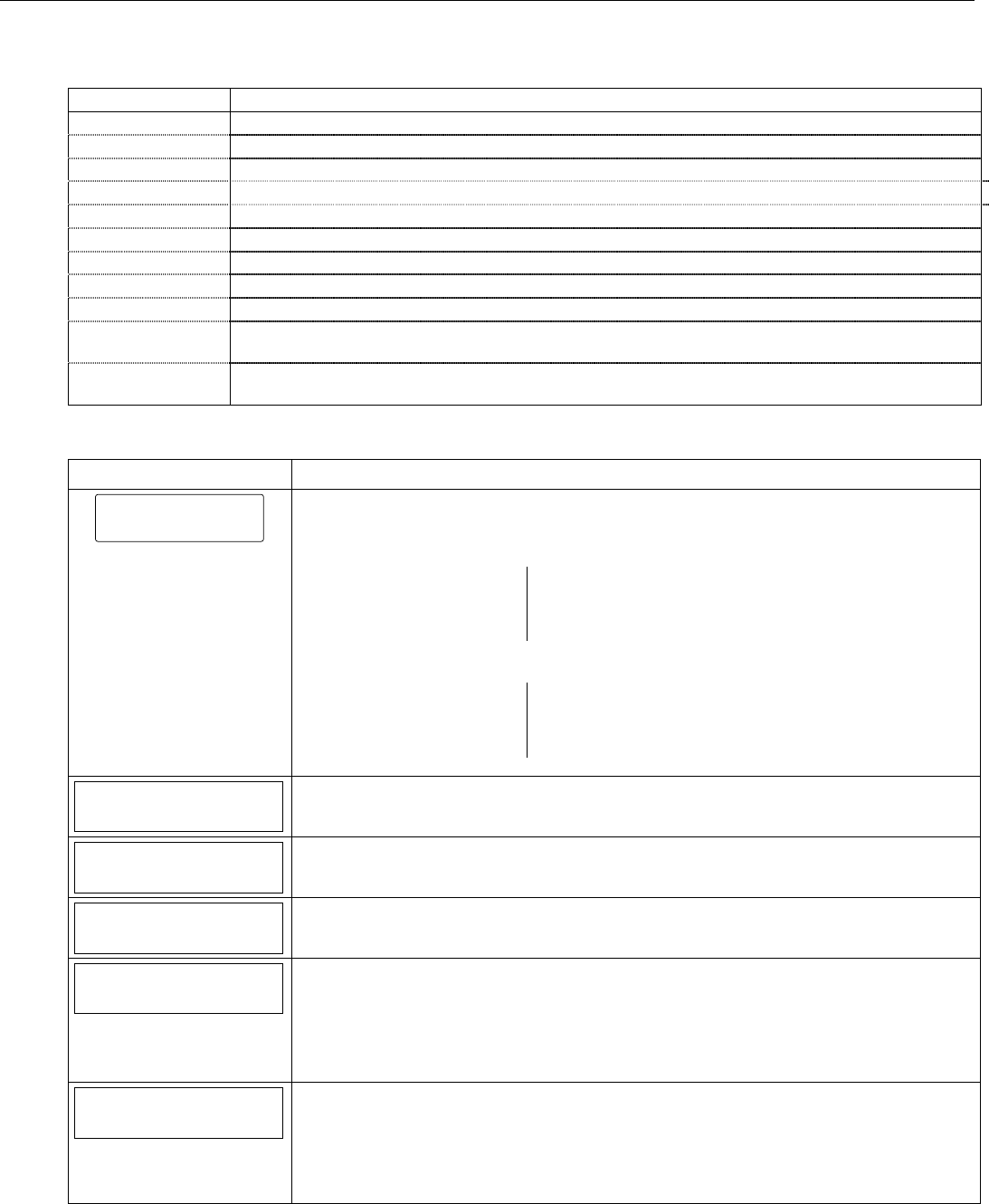
Change Installer Code
The factory default Installer Code for the LYNX Touch Control is set to 4-1-1-2.
SCREEN ACTION
5000-100-129-V0
Installer Code
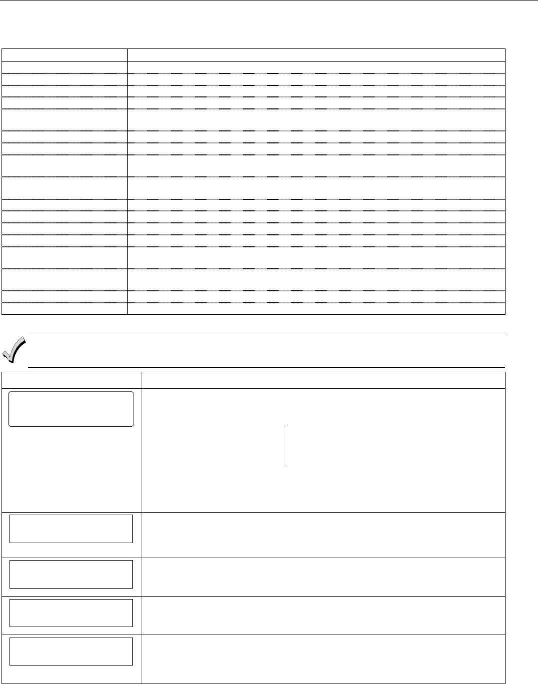
1. Select “Installer Code”.
2. Enter a new four-digit Installer Code on the displayed keypad The system will display the
new code on the left side of the screen.
3. Select “Done” when you are finished.
4. The system returns to the “System Programming” Screen.
LYNX Touch Installation and Setup Guide
- 21 -
Programming the Control
System Type
The following system options are programmed in this section:
Option Function
RF Jam Enable or disable RF Jam Log and Reporting
Speaker Phone Enable or disable Speaker Phone mode. (End User feature)
Two Way Voice Enable or disable Two Way Voice communication with the Central Station.
RF House Code Set RF House Code. (Bi-directional RF Devices)
Phone Notification Enable or disable Phone Notification mode. (Phone Line-cut)
Phone Detect Time Select a delay period between phone line-cut & system response (allows phone to restore)
Remote Phone Enable or disable Remote Phone Control mode. (End User feature)
Events Enable or disable multiple options for event logging (i.e.; alarms, troubles, open/close)
Non-Security Enable or disable non-security event logging
Remote Access
Serial
Enable or disable end user to access their system via a website
Multi Mode Serial Enable or disable transmission of panel status events via email (Active only when Remote Access
Serial is enabled)
Note: If applicable, preprogrammed defaults for the LYNX Touch Control are shown on the screen unless
otherwise noted.
Screen ACTION
5000-100-130-V0
System Type
System Type
Note: If applicable, the pre-programmed default will be displayed beneath the option.
1. Select “System Type” from the following options:
RF Jam Speaker Phone
Two Way Voice RF House Code
Phone Notification Remote Phone
Phone Detect Time
Use the down T arrow to scroll to the next page of options.
Events – Log All Events – Log Alarm
Events – Log Bypass Events – Log Open/Close
Events – Log Trouble Non-Security
Remote Access Serial Multi Mode Serial
Speaker Phone
Enabled
3. Select “Speaker Phone”. The System toggles between the following:
Disabled
Enabled
Two Way Voice
Disabled
4. Select “Two-Way Voice” .The System toggles between the following:
Disabled
Enabled
RF House Code
0
5. Select “RF House Code”.
6. After entering a code (00-31) on the displayed keypad, select “Done”.
Phone Notification
Disabled
7. Select “Phone Notification” (phone line cut). The System scrolls between the following
options:
Disabled
Keypad
Trouble
If “Keypad” or “Trouble is selected proceed to Step 8.
Phone Detect Time
2 Minutes
8. If Keypad or Trouble was selected in Step 7, the “Phone Detect Time” option is
displayed. Select “Phone Detect Time”. The system scrolls between the following options:
1 Minute
2 Minutes
3 Minutes
4 Minutes
LYNX Touch Installation and Setup Guide
- 22 -
Programming the Control
Screen ACTION
Remote Phone
Enabled
9. Select “Remote Phone”. The System toggles between the following options:
Disabled
Enabled
Events - Log All
Press To Log All
Use the down T arrow to scroll to the next page of options.
10. Select “Events - Log All”. The system displays “Press To Log All”. Selecting this option
programs the system to log all events and “Log All Set” is displayed. Additionally all of the
options listed below are enabled.
Events – Log Alarm
Events – Log Bypass
Events – Log Open/Close
Events – Log Trouble
Non-Security
OR
Proceed to step 11 and select the options individually.
Events – Log Alarm
Enabled
11. Select “Events – Log Alarm”. The System toggles between “Enabled” and “Disabled.
12. Select “Events – Log Bypass”. The System toggles between “Enabled” and “Disabled”.
13. Select “Events – Log Open/Close”. The System toggles between “Enabled” and
“Disabled”.
14. Select “Events – Log Trouble”. The System toggles between “Enabled” and “Disabled”.
Remote Access Serial
Disabled
15. Select “Remote Access Serial”. The System toggles between “Enabled” and “Disabled”.
If the Remote Access Serial” option is enabled, the “Multi Mode Serial” option is
displayed.
Non Security
Disabled
16. Select “Non Security”. The System toggles between “Enabled” and “Disabled”.
Multi Mode Serial
Disabled
17. Select “Multi Mode Serial”. The System toggles between “Enhanced Reports” and
“Disabled”.
18. Select “Save” when complete.
LYNX Touch Installation and Setup Guide
- 23 -
Programming the Control
Program Date and Time
Note: If applicable, preprogrammed defaults for the LYNX Touch Control are shown on the screen unless otherwise noted.
SCREEN ACTION
5000-100-131-V0
Date Time
Note: If you are installing a GSMVLP5 or ILP5 Communication Module, the
time and date will be programmed and updated automatically via
Central Station. You must still program the correct Time Zone below.
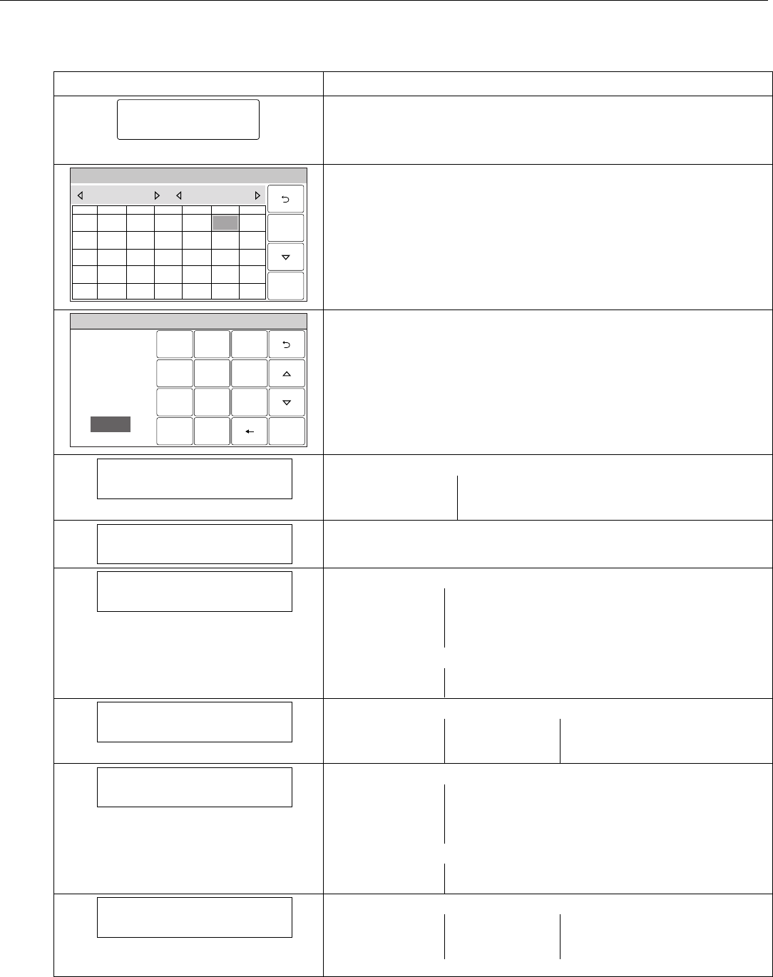
1. Select “Date Time”.
System Programming...
5000-100-016-V0
THUSUN WED
32
SAT
6
FRI
5
TUEMON
1
1817
20
191614 15
2524
27
262321 22
3028 29
1110
13
129
78
June 2010
4
Save
2. Using the left W and right X arrows select the Month and Year then
select the date. Select the T key to advance to the next screen.
System Programming
231
564
0
897
Clear
5000-100-010-V0
AM / PM
Enter Time
10:21 AM
Save
3. To set the correct time, touch the “Clear” button.
4. Enter the correct time and then select AM or PM. Select the T key to
advance to the next screen or select “Save” to return to the System
Programming Screen.
Time Zone
Eastern (EST)
6. Select “Time Zone”. The system scrolls between the following options:
Eastern (EST) Mountain (MST)
Central (CST) Pacific (PST)
Hawaii (HAST) Alaska (AKST)
Day Light Savings Time
Yes
6. Select “Day Light Savings Time”. The system toggles between “Yes” and
“No”. If “Yes” is selected the following options will become active.
Start Month
March
7. Select “Start Month”. The system displays the following options.
January February
March April
May June
July August
Use the down T arrow to scroll to the next page of options.
September October
November December
Start Week
Second
8. Select “Start Week”. The system scrolls between the following options.
First Fourth 3rd from Last
Second Last
Third Next to Last
End Month
November
9. Select “End Month”. The system displays the following options.
January February
March April
May June
July August
Use the down T arrow to scroll to the next page of options.
September October
November December
End Week
First
10. Select “End Week”. The system will scrolls through the available weeks.
First Fourth 3rd from Last
Second Last
Third Next to Last
11. After programming these options, select the “Save” key.
LYNX Touch Installation and Setup Guide
- 24 -
Programming the Control
Program the Communications Module
The following system options are programmed in this section:
Option Function
Communications Path Selects type of Communications Module
Primary City Id Enter Central Station Primary City ID
Primary Central Station Id Enter Primary Central Station ID
Primary Subscriber Id Enter Central Station Primary Subscriber ID
Supervision Selects how often the Communications Module sends a supervisory message to the Central
Station.
Old Alarm Time Selects how long an undeliverable alarm delivery is retried to the Central Station.
Remote Acc. IP or GSM Enables or disables user remote access via internet and/or GSM.
Multi Mode IP or GSM (appears only if Remote Access IP or GSM is enabled.) Enables or disables multi mode
feature.
IP Fault Time (Appears only if IP is enabled in Communications Path field.) Selects time delay before the
Communications Module notifies the control panel of a loss of contact with the internet.
Use DHCP Dynamically selects the IP addresses
NIC IP Address (Appears only if “No” is selected in Use DHCP field.) Enter NIC IP Address.
Subnet Mask (Appears only if “No” is selected in Use DHCP field.) Enter Subnet Address.
Gateway IP Address (Appears only if “No” is selected in Use DHCP field.) Enter Gateway IP Address
DNS Server IP Address (Appears only if “No” is selected in Use DHCP field.) Enter Domain Name Server IP
Address.
GSM Fault Time (Appears only if GSM is enabled in Communications Path field.) Selects time delay before
the Communications Module notifies the control panel of a loss of contact with the network.
GSM Rollover Allows messages to be sent over GSM in the event that contact with the internet is lost.
GSM 24 Hour Test Enables daily test of GSM module operation.
Note: If applicable, preprogrammed defaults for the LYNX Touch Control are shown on the screen unless otherwise noted.
Remote Access (Total Connect) and Multi Mode (PSD) over IP or GSM cannot be enabled in the panel alone.
Availability of this service is controlled via the web-based programming tool on the AlarmNet Direct website. These
features must to be enabled through the AlarmNet Direct website first and transferred to the device.
SCREEN ACTION
5000-100-132-V0
Communicator
Communicator
1. Select “Communicator”
The System displays the following options:
Communications Path Primary City Id
Pri Central Station Id Primary Subscriber Id
Supervision Old Alarm Time
Remote Acc. IP or GSM Multi Mode IP or GSM
Use the down T arrow to scroll to the next page of options.
GSM Fault Time
OR
IP Fault Time
Communications Path
None
2. Select “Communications Path”. The system scrolls between the following options:
None
IP
GSM
Primary City Id
3. Select “Primary City Id”. Enter the 2-digit Primary City ID (Decimal).
Options
01-99
Pri Central Station Id
4. Select “Pri Central Station Id”. Enter the 2-digit Primary Central Station ID (HEX).
Options
01-FE
Primary Subscriber Id
5. Select “Primary Subscriber Id”. Enter the 4-digit Subscriber Account Number
(Decimal).
Options
0001-9999
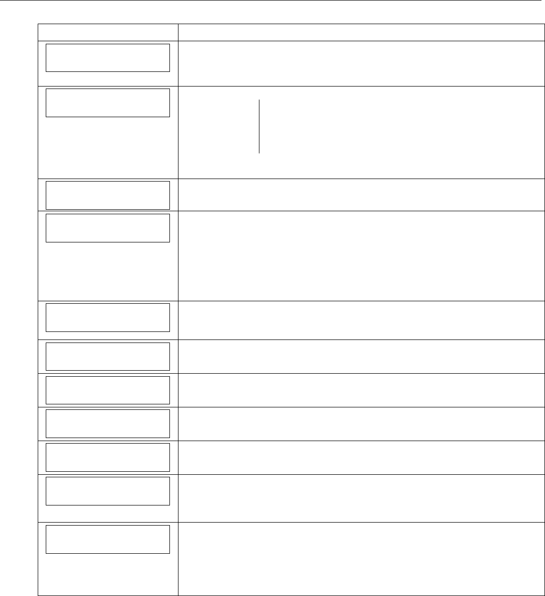
LYNX Touch Installation and Setup Guide
- 25 -
Programming the Control
SCREEN ACTION
Supervision
24 Hours
6. Select “Supervision”. The system scrolls between the following options:
24 Hours
None
30 Days
Old Alarm Time
10 Minutes
7. Select “Old Alarm Time”. The system scrolls between the following options:
10 Minutes 15 Minutes
30 Minutes 1 Hour
2 Hours 4 Hours
8 Hours 12 Hours
Use the down T arrow to scroll to the next page of options.
24 Hours
Remote Acc. IP or GSM
Disabled
8. Select “Remote Acc. IP or GSM”. The system toggles between “Disabled” and
“Enabled”.
Multi Mode IP or GSM
Disabled
9. If “Remote Access IP or GSM” was enabled in the previous step, the “Multi Mode IP
or GSM” option is displayed. The system scrolls between the following options.
Disabled
Relay Reports
Enhanced Reports
10. Use the down T arrow to scroll to the next page of options. If IP or IP & GSM was
selected in step 2, proceed to step 11. If GSM was selected in step 2, proceed to
step 19.
IP Fault Time
00
11. Select “IP Fault Time”. Enter the time delay (in minutes) on the displayed keypad.
Options
00-99
Use DHCP
Yes
13. Select “Use DHCP”. The system toggles between “Yes” and “No”. If “No” is selected
the system displays four additional options. If “Yes” is selected, skip to step 18.
NIC IP Address
255.255.255.255
14. Select “NIC IP Address”. Enter the 4-part address on the displayed keypad.
Subnet Mask
255.255.255.255
15. Select “Subnet Mask”. Enter the 4-part address on the displayed keypad.
Gateway IP Address
255.255.255.255
16. Select “Gateway IP Address”. Enter the 4-part address on the displayed keypad.
DNS Server IP Address
255.255.255.255
17. Select “DNS Server IP Address”. Enter the 4-part address on the displayed keypad.
18. If “IP” was selected in step 2, select “Save” and then select “OK” when the
“Programming Done” screen appears. Proceed to “Diagnostics” section in order to
register the device.
GSM Fault Time
00
19. Select “GSM Fault Time”. Enter the time delay (in minutes) on the displayed keypad.
Options
00-99
20. If “GSM” was selected in step 2, select “Save” and then select “OK” when the
“Programming Done” screen appears. Proceed to “Diagnostics” section in order to
register the device.
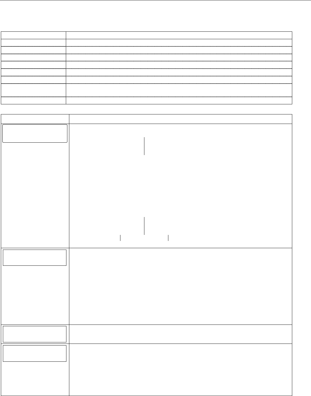
LYNX Touch Installation and Setup Guide
- 26 -
Programming the Control
Program Zones
The following system options are programmed in this section:
Option Function
Serial Number Manually enter device serial number or enroll via RF transmission
Loop Number Manually enter device loop number or enroll via RF transmission
Zone Description 1/2 Enter Zone Descriptors for the device being enrolled
Device Type Select the type of device being enrolled
Response Type Select the alarm response for the device being enrolled (refer to Zone Response Type Table)
Alarm Report Activate reporting option for the device being enrolled
Chime Enable/disable chime mode for specific device being enrolled (applies to Entry/ Exit, Perimeter,
and Interior Response types only)
Supervision Select supervision for device being enrolled
Note: If applicable, preprogrammed defaults for the LYNX Touch Control are shown on the screen unless otherwise noted.
SCREEN ACTION
5000-100-133-V0
Zones
1. Select “Zones”
The System displays the following options:
1. New
3. Back Door
5. Motion Sensor
2. Front Door
4.Window
6.New
2. Use the down T arrow to scroll to the next page of options. Use the S arrow to return to
the previous page.
7. – 48. New
49. – 56. 4 Button
57. – 64. New
95. Fire
96. Medical
99. Police
3. Select a zone and then select “Edit” or “Add New” to program the next available zone. The
following options are displayed (dependant upon Zone Type):
Serial Number Loop Number
Zone Description 1 Zone Description 2
Device Type Response Type
Alarm Report Chime Supervision
4. Select an option to display the next programming field.
Serial Number
Serial Number
When “Serial Number” has been selected “Enter Serial Number or Activate” is displayed. The
transmitter serial number and loop number can be enrolled via RF transmission OR manually.
Enroll via RF Learning To enroll the device using RF Learning mode three transmissions
(open/close) of the device will be required. The initial transmission activates the RF Learning
mode and the system will emit a single beep. A second transmission enrolls the serial number
and the system beeps two times and displays “Activate Sensor Again To Confirm”. A third
transmission will confirm the serial number. The system beeps two times and returns to the
Zone programming Screen.
Enroll Manually
Enter the 7-digit serial number printed on the transmitter using the displayed keypad and
select “Done”. The system beeps one time and returns to the Zone programming Screen.
Loop Number
1
Loop Number
Select “Loop Number” to toggle between 1, 2, 3 and 4. Enter Save.
Zone Description 1
Zone Description 1
Select “Zone Description 1”. Using the displayed keypad enter Zone Description 1. The
system announces the Zone Description. Enter “Done”, when you are finished. The system
returns to the Zone Programming page.
Zone Description 2
Select “Zone Description 2”. Using the displayed keypad enter Zone Description 2. The
system announces the Zone Description. Enter “Done”, when you are finished. The system
returns to the Zone Programming page.
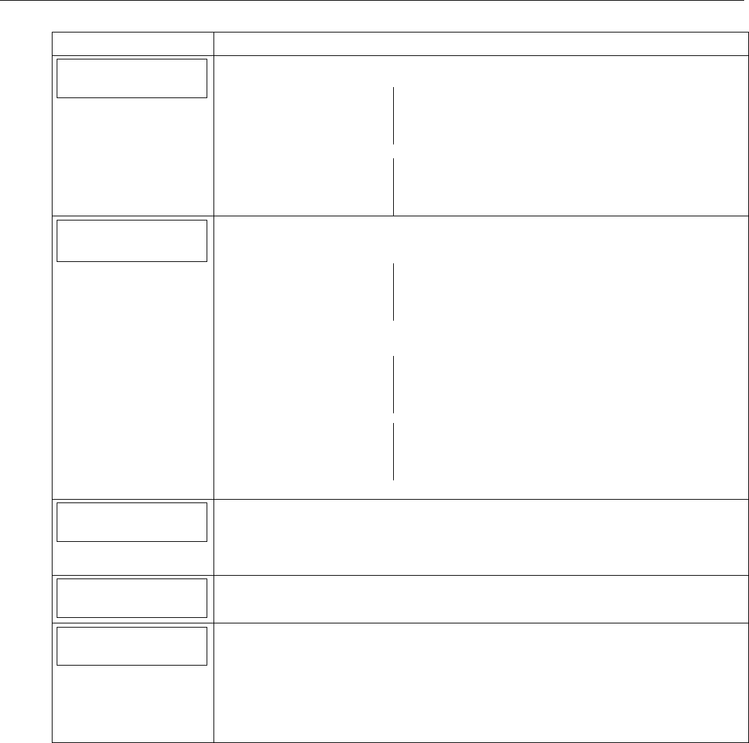
LYNX Touch Installation and Setup Guide
- 27 -
Programming the Control
SCREEN ACTION
Device Type
Device Type
Select “Device Type”. The system displays the following options (dependant upon the Zone):
New Door
Window Motion Sensor
Glass Break Smoke Detector
Heat Sensor Carbon Mono. Det.
Use the down T arrow to scroll to the next page of options:
Temperature Flood
Environmental Medical
Fire Police
Other
Response Type
Not Used
Response Type
1. Select “Response Type”. The system displays the following options (dependant upon the
Zone):
Not Used Entry Exit 1
Entry Exit 2 Perimeter
Interior Follower Trouble Alarm
24 Hour Silent 24 Hour Audible
2. Use the down T arrow to scroll to the next page of options. Use the S arrow to return to
the previous page.
24 Hour Auxiliary Fire No Verification
Interior With Delay Monitor
Carbon Monoxide Trouble
Arm Stay Arm Away
Disarm No Response
Silent Burglary Resident Monitor
Resident Response General Monitor
General Response Fire With Verification
3. Select Response Type and select “Save”. The system will return to the Zone screen
Alarm Report
Yes
Alarm Report
Note: This field is for Alarms. If Response Type “Trouble” is set up and Alarm Report is set to
“No” the system will still report if Report Alarms was enabled in the Reporter
programming.
Select “Report” to toggle between “No” or “Yes”. Select “Save”.
Chime
No
Chime
Note: Chime only applies to entry/exit, perimeter and interior zone types.
Select “Chime” to toggle between “No” or “Yes”. Select “Save”.
Supervision
Supervised
Supervision
Select “Supervision” to scroll between the following options:
Hardwire – Normally Open
Hardwire – Normally Closed
Hardwire – End of Line
RF – Supervised
RF – Unsupervised
After making a Supervision selection, select “Save”.
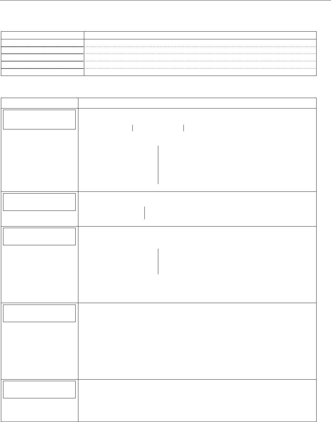
LYNX Touch Installation and Setup Guide
- 28 -
Programming the Control
Program Keys
The following system options are programmed in this section:
Option Function
Key Type Select the specific type of key being entered or enrolled
User Associates the Key with a specific User
Serial Number Manually enter key serial number or enroll via RF transmission
Zone Manually enter key zone number (between 49 and 64) or enroll via RF transmission
Button Key * - Zn * Associate the selected button with a specific function
* Key number and Zn number are dependant upon the Key Type selected.
Note: If applicable, preprogrammed defaults for the LYNX Touch Control are shown on the screen unless otherwise noted.
SCREEN ACTION
Keys
1. Select “Keys”
The System displays the following options:
Edit Add New Delete
2. Select “Add New”.
3. The following options are displayed (dependant upon the “Key Type” selected):
Key Type User
Serial Number Zone
Button Key 1 – Zn 49 Button Key 2 – Zn 50
Button Key 3 – Zn 51 Button Key 4 – Zn 52
Button Key 5 – Zn 53 Button Key 6 – Zn 54
Button Key 7 – Zn 55 Button Key 8 – Zn 56
4. Select an option to display the next programming field.
Key Type
4 Button key
Key Type
Select “Key Type”. The system scrolls between the following:
1 Button key 6 Button key
2 Button key 8 Button key
4 Button key
User
User
4. Select “User” then select from the following options (or the list of Users that have been
programmed):
Master Babysitter
Duress User 3
User 4 User 5
User 6 User 7
Use the down T arrow to scroll to the next page. The system displays options for User 8
through 14.
Note: The Key must be associated with a specific User/User Code in order for it to operate.
Refer to the LYNX Touch User Guide for additional Information regarding User Codes.
Serial Number
0
Serial Number
When “Serial Number” has been selected “Enter Serial Number or Activate” is displayed. The
transmitter serial number and loop number can be enrolled via RF transmission OR manually.
Enroll via RF Learning To enroll the device using RF Learning mode three transmissions
(open/close) of the device will be required. The initial transmission activates the RF Learning
mode. A second transmission enrolls the serial number and the system beeps two times and
displays “Activate Sensor Again To Confirm”. A third transmission will confirm the serial
number. The system beeps three times and returns to the Zone programming Screen.
Enroll Manually
Enter the 7-digit serial number printed on the transmitter using the displayed keypad and
select “Done”. The system beeps one time and returns to the Zone programming Screen.
Zone
49
Zone
The system displays the next available key Zone number. Select “Zone” to manually enter a
specific Zone Number on the displayed keypad (49-64). If the desired Zone Number is not
available, the system returns to the previous screen.
Select ”Done”. The system returns to the previous screen. Repeat the previous step to enter
another Zone Number.

LYNX Touch Installation and Setup Guide
- 29 -
Programming the Control
SCREEN ACTION
Button Key * - Zn *
Button Key * Zn *
Select the desired Button Key and enter a function for each button key. The system
displays the following options:
Disarm Arm Away
Arm Stay No Response
24 Hour Silent 24 Hour Audible
24 Hour Auxiliary Silent Burglary
Fire No Verification
* Options are the same for each Button/Zone combination.

LYNX Touch Installation and Setup Guide
- 30 -
Programming the Control
Reporter
When Compass service is required and GSM or IP are the only reporting channels: As part of Primary Central
Station programming; the “Phone Type” must be set to any selection other than “None”, the “Communicator Type”
must be set to GSM or IP, as applicable, and must match the compass value; “Phone number” field must be left
blank and an “Account number” must be programmed.
The following system options are programmed in this section:
Option Function
Prim. or Sec. Central Station Enroll information pertaining to the Primary and/or Secondary Central Station.
Phone Type Select the Report Format that will be used to send reports to the Primary or Secondary
Central Station, as applicable.
Phone Number Enter the Phone Number for the Primary or Secondary Central Station, as applicable.
Communicator Type Select the type of Communications Module that will be used to communicate with the
Primary or Secondary Central Station, as applicable.
Account Number Enter the account number for the Primary or Secondary Central Station, as applicable.
Dynamic Priority Select the primary method for sending Reports to the Primary or Secondary Central
Station, as applicable.
Dynamic Delay Selects delay between switching between reporting methods. Active if Dynamic Delay
feature has been set to Preferred Telco or Preferred Radio.
Report All Enable All Reports to be sent to the Primary or Secondary Central Station, as applicable.
Report Alarms Enable Alarm Reporting to the Primary or Secondary Central Station, as applicable.
Report Troubles Enable Trouble Reporting to the Primary or Secondary Central Station, as applicable.
Report Open/Close Enable Open/Close Reporting to the Primary or Secondary Central Station, as applicable.
Report Tests Enable Test Reporting to the Primary or Secondary Central Station, as applicable.
Phone 1 or Phone 2 Enroll information Primary and/or Secondary telephone numbers for “Follow Me”
Announcements and/or Reminders.
Phone Type Enter Number for Phone 1 or Phone 2, as applicable.
Phone Number Enter Primary and/or Secondary telephone numbers for “Follow Me” Announcements
and/or Reminders.
Report All Enable All Reports to be sent to the Phone 1 or Phone 2, as applicable.
Report Alarms Enable Alarm Reporting to the Phone 1 or Phone 2, as applicable.
Report Troubles Enable Trouble Reporting to the Phone 1 or Phone 2, as applicable.
Report Open/Close Enable Open/Close Reporting to the Phone 1 or Phone 2, as applicable.
Report Tests Enable Test Reporting to the Phone 1 or Phone 2, as applicable.
Report Selection Enable Reporting of Specific Events
Options
PBX Enter the digits required to access an outside line, if applicable
Call Wait Cancel Enter the digits required to cancel call waiting, if applicable
Number of Reports Limit the number of messages sent to the Central Station during an armed period.
(applies to LYNX Touch only)
Alarm Report Delay Disable or select the time delay for alarm reporting (applies to LYNX Touch only)
Swinger Shutdown Select the number of times reports are sent and sounder sounds for non-fire alarms
before the system ignores subsequent alarms (applies to LYNX Touch SIA only)
Abort Window Select the time delay for alarm reporting (applies to LYNX Touch SIA only)
First Offset Report Select the time for the first test report following power-up/programming or downloading
Report Frequency Select the test report frequency
Downloader
Phone Answer Enable or disable to allow control to answer incoming phone line.
Modem Speed (Future Use)
Ans. Machine Defeat Enable to defeat answering machine mode. (Active if Phone Answer is enabled.)
Ring Counter Enter the number of rings before control picks up phone line. (Active if Ans. Machine
Defeat is not enabled.)
Callback Number Enter the phone number the control will use to call back the downloading computer.
(Active if Phone Answer is enabled.)
Flexible Callback Allows Download operator to temporarily change the callback number by the number of
digits selected. Active if Phone Answer is enabled
Number Enter the number of flexible callback numbers that will be used. Active if Flexible Callback
is enabled.
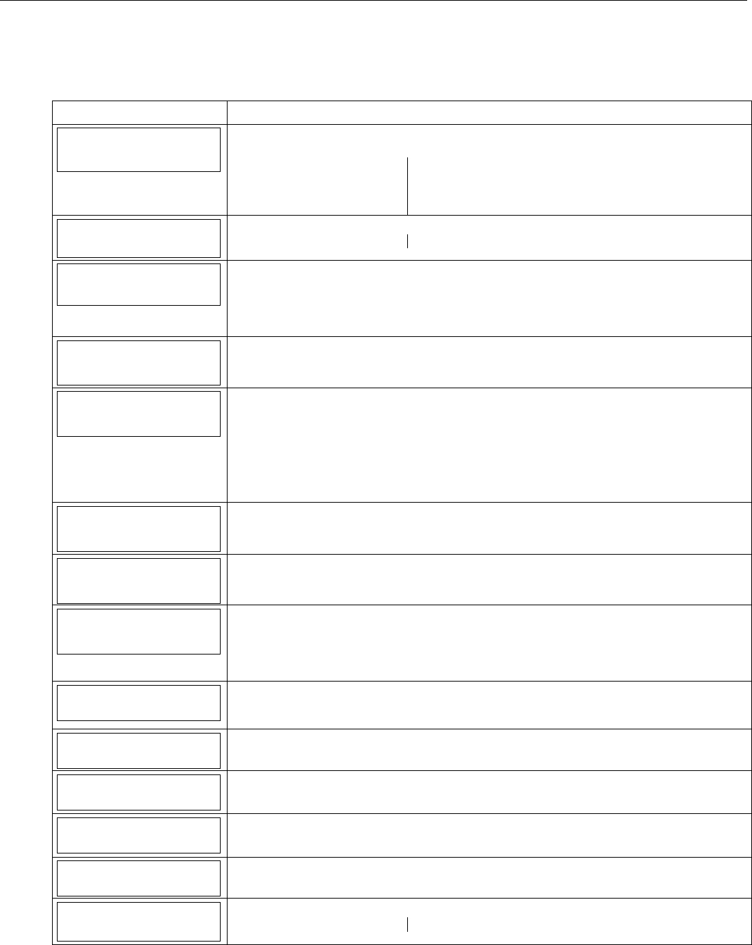
LYNX Touch Installation and Setup Guide
- 31 -
Programming the Control
Notes: If applicable, preprogrammed defaults for the LYNX Touch Control are shown on the screen unless
otherwise noted.
When GSM is used as the Primary Communications channel for any Total Connect service, the GSM
Radio must be selected as the Primary Reporting Path (Preferred Radio).
SCREEN ACTION
Reporter
Select “Reporter”
The System displays the following options:
Primary Central Station Secondary Central Station
Phone 1 Phone 2
Report Selection Options
Downloader
Primary
Central Station
Select “Primary Central Station”. The System displays the following options:
Phone Type Communicator Type
Phone Type
Contact Id: 4 Digit
Select “Phone Type”. The System scrolls though the following options:
None
Contact Id: 4 Digit
Contact Id: 10 Digit
SIA
Phone Number
If any option other than “None” is selected in “Phone Type” The “Phone Number” option will
be displayed. Select “Phone Number”. Enter the Primary Central Station Phone Number on
the displayed keypad.
Communicator Type
None
Select “Communicator Type”. The System scrolls though the following options:
None
GSM
IP
Note: The system will display the communications (GSM or IP) path that was selected in
Communications Programming. The Communication Path selection can be enabled for either
Primary Central Station or Secondary Central Station but not both. If it is enabled in one it will
not be available for the other Central Station.
Account Number
FFFF
If any option other than “None” is selected in “Phone Type” The “Account Number” option
will be displayed. Select “Account Number”. Enter the Primary Central Station Account
Number on the displayed keypad.
Dynamic Priority
Redundant Reports
If any option other than “None” is selected in “Communicator Type” The “Dynamic Priority”
option will be displayed. “Select “Dynamic Priority”. The system scrolls between “Redundant
Reports”, “Preferred Telco” and Preferred Radio”.
Dynamic Delay
30 Seconds
If any option other than “Redundant Reports” is selected in “Dynamic Priority” The “Dynamic
Delay” option will be displayed. “Select “Dynamic Delay”. The system scrolls between “15
Seconds”, “30 Seconds”, “60 Seconds” and “90 Seconds”.
Note: If GSM is selected as the primary reporting channel Dynamic Delay should be set to minimum
of 60 seconds.
Report All
Press to Report All
Select “Report All”. The System toggles between “Press to Report All” and “Report All Set”.
If “Report All” is selected all reporting options will be “Enabled”. Select the “Save” key to
return to the Reporter options screen.
Report Alarms
Disabled
Select “Report Alarms”. The System toggles between “Disabled” and “Enabled”.
SIA: The LYNX Touch SIA default is “Enabled”.
Report Troubles
Disabled
Select “Report Troubles”. The System toggles between “Disabled” and “Enabled”.
SIA: The LYNX Touch SIA default is “Enabled”.
Report Open/Close
Disabled
Select “Open/Close”. The System toggles between “Disabled” and “Enabled”.
Report Tests
Disabled
Select “Report Tests”. The System toggles between “Disabled” and “Enabled”.
Secondary
Central Station
Select “Secondary Central Station”. The System displays the following options:
Phone Type Communicator Type
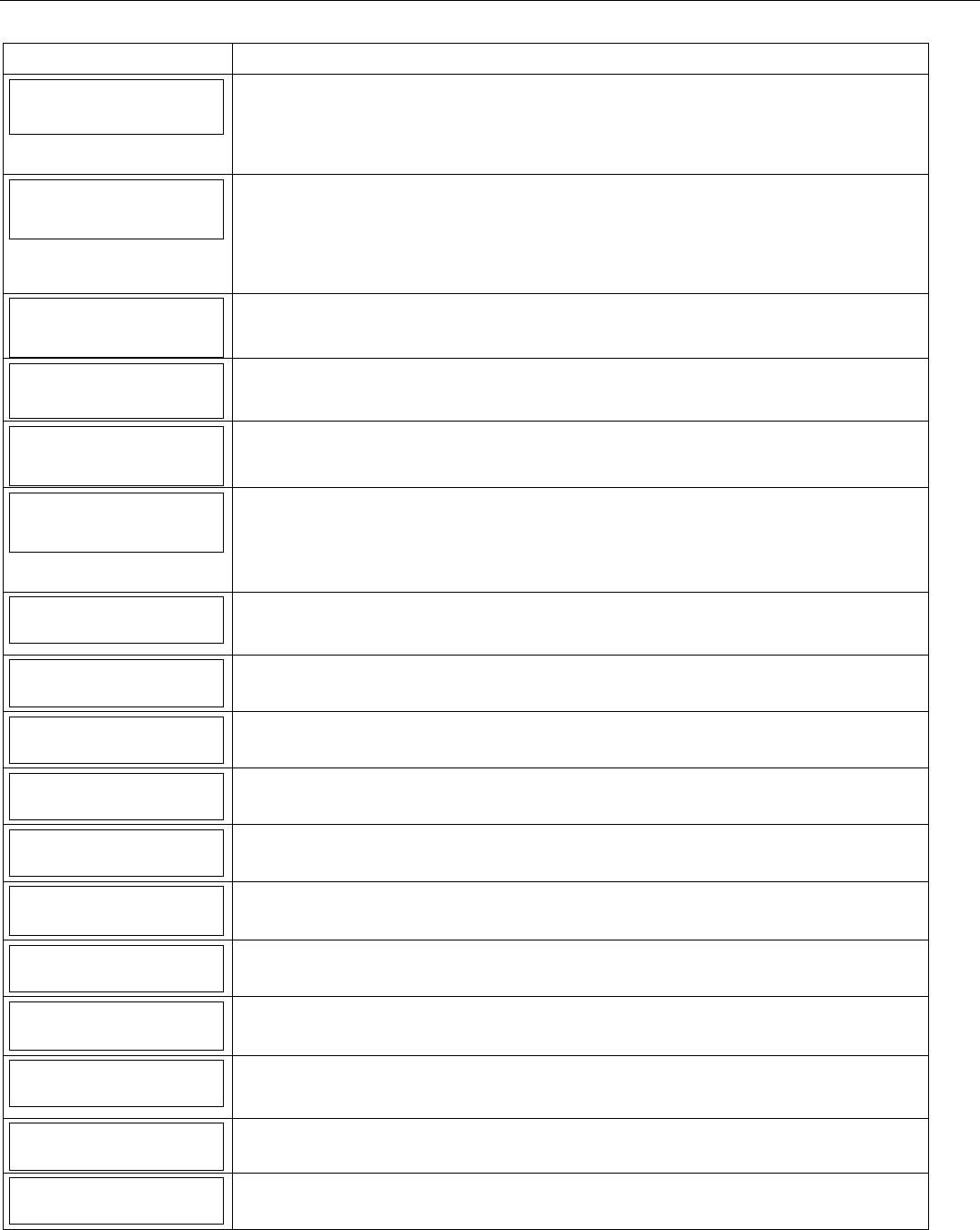
LYNX Touch Installation and Setup Guide
- 32 -
Programming the Control
SCREEN ACTION
Phone Type
None
Select “Phone Type”. The System displays the following options:
None
Contact Id: 4 Digit
Contact Id: 10 Digit
SIA
Communicator Type
None
Select “Communicator Type”. The System displays the following options:
None
GSM or IP
Note: The system will display the communications path (GSM or IP) selected in Communications
Programming. The path can be enabled for either primary Central Station or Secondary Central
Station but not both. If it is enabled in one it will not be available for the other Central Station.
Phone Number
If any option other than “None” is selected in “Phone Type”, the “Phone Number” option will
be displayed. Select “Phone Number”. Enter the Secondary Central Station Phone Number
on the displayed keypad.
Account Number
FFFF
If any option other than “None” is selected in “Phone Type” The “Account Number” option will
be displayed. Select “Account Number”. Enter the Secondary Central Station Account
Number on the displayed keypad.
Dynamic Priority
Redundant Reports
If any option other than “None” is selected in “Communicator Type” The “Dynamic Priority”
option will be displayed. “Select “Dynamic Priority”. The system scrolls between “Redundant
Reports”, “Preferred Telco” and Preferred Radio”.
Dynamic Delay
30 Seconds
If any option other than “Redundant Reports” is selected in “Dynamic Priority” The “Dynamic
Delay” option will be displayed. “Select “Dynamic Delay”. The system scrolls between “15
Seconds”, “30 Seconds”, “60 Seconds” and “90 Seconds”.
Note: If GSM is selected as the primary reporting channel Dynamic Delay should be set to
minimum of 60 seconds.
Report All
Press to Report All
Select “Report All”. The System toggles between “Press to Report All” and “Report All Set”. If
“Report All” is selected all reporting options will be “Enabled”. Select the “Save” key to return
to the Reporter options screen.
Report Alarms
Disabled
Select “Report Alarms”. The System toggles between “Disabled” and “Enabled”.
Report Troubles
Disabled
Select “Report Troubles”. The System toggles between “Disabled” and “Enabled”.
Report Open/Close
Disabled
Select “Open/Close”. The System toggles between “Disabled” and “Enabled”.
Report Tests
Disabled
Select “Report Tests”. The System toggles between “Disabled” and “Enabled”.
Phone 1
Select “Phone 1” to program the “Follow Me” Reminder telephone number 1
Phone Type
None
Select “Phone Type”. The System toggles between “None” and “Follow Me”.
Phone Number
Select “Phone Number”. Enter the “Follow Me” Phone Number 1 on the displayed keypad.
Report All
Press to Report All
Select “Report All”. The System toggles between “Press to Report All” and “Report All Set”. If
“Report All” is selected all reporting options will be “Enabled”. Select the “Save” key to return
to the Reporter options screen.
Report Alarms
Disabled
Select “Report Alarms”. The System toggles between “Disabled” and “Enabled”.
Report Troubles
Disabled
Select “Report Troubles”. The System toggles between “Disabled” and “Enabled”.
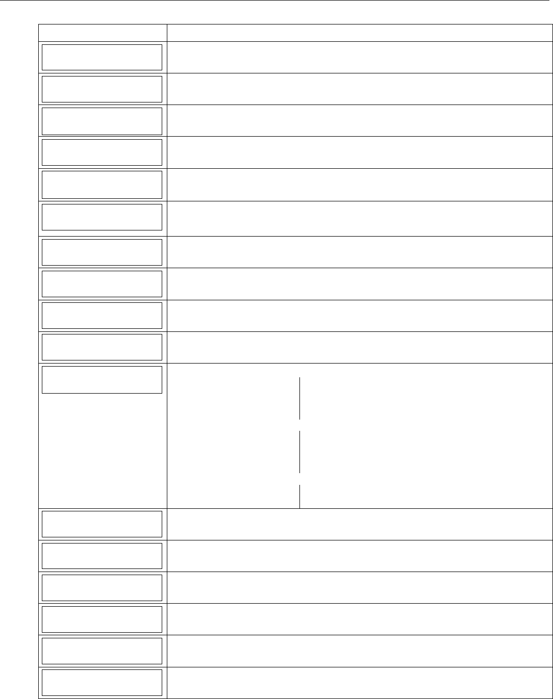
LYNX Touch Installation and Setup Guide
- 33 -
Programming the Control
SCREEN ACTION
Report Open/Close
Disabled
Select “Open/Close”. The System toggles between “Disabled” and “Enabled”.
Report Tests
Disabled
Select “Report Tests”. The System toggles between “Disabled” and “Enabled”.
Phone 2
Select “Phone 2” to program the “Follow Me” Reminder telephone number 2.
Phone Type
None
Select “Phone Type”. The System toggles between “None” and “Follow Me”.
Phone Number
Select “Phone Number”. Enter the “Follow Me” Phone Number 2 on the displayed keypad.
Report All
Press to Report All
Select “Report All”. The System toggles between “Press to Report All” and “Report All Set”.
If “Report All” is selected all reporting options will be “Enabled”. Select the “Save” key to
return to the Reporter options screen.
Report Alarms
Disabled
Select “Report Alarms”. The System toggles between “Disabled” and “Enabled”.
Report Troubles
Disabled
Select “Report Troubles”. The System toggles between “Disabled” and “Enabled”.
Report Open/Close
Disabled
Select “Open/Close”. The System toggles between “Disabled” and “Enabled”.
Report Tests
Disabled
Select “Report Tests”. The System toggles between “Disabled” and “Enabled”.
Report Selection
Select “Report Selection”. The System displays the following options:
Arm Away Arm Stay
Disarm Exit Error
Recent Closing Event Log Full
Trouble Trouble Restore
Use the down T arrow to scroll to the next page of options.
Alarm Restore Alarm Cancel
Test Test Restore
Bypass Bypass Restore
AC Loss AC Loss Restore
Use the down T arrow to scroll to the next page of options.
Low Battery Low Battery Restore
RF Low Battery RF Low Battery Restore
Arm Away
Enabled
Select “Arm Away”. The System toggles between “Disabled” and “Enabled”.
Arm Stay
Enabled
Select “Arm Stay”. The System toggles between “Disabled” and “Enabled”.
Disarm
Enabled
Select “Disarm”. The System toggles between “Disabled” and “Enabled”.
Exit Error
Enabled
Select “Exit Error”. The System toggles between “Disabled” and “Enabled”.
Recent Closing
Enabled
Select “Recent Closing”. The System toggles between “Disabled” and “Enabled”.
Note: In the LYNX Touch SIA control, this field is always “Enabled”.
Event Log Full
Enabled
Select “Event Log Full”. The System toggles between “Disabled” and “Enabled”.
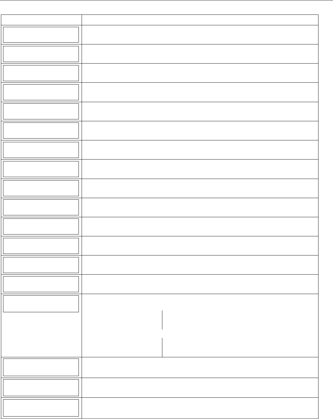
LYNX Touch Installation and Setup Guide
- 34 -
Programming the Control
SCREEN ACTION
Trouble
Enabled
Select “Trouble”. The System toggles between “Disabled” and “Enabled”.
Trouble Restore
Enabled
Select “Trouble Restore”. The System toggles between “Disabled” and “Enabled”.
Alarm Restore
Enabled
Select “Alarm Restore”. The System toggles between “Disabled” and “Enabled”.
Alarm Cancel
Enabled
Select “Alarm Cancel”. The System toggles between “Disabled” and “Enabled”.
Test
Enabled
Select “Test”. The System toggles between “Disabled” and “Enabled”.
Test Restore
Enabled
Select “Test Restore”. The System toggles between “Disabled” and “Enabled”.
Bypass
Enabled
Select “Bypass”. The System toggles between “Disabled” and “Enabled”.
Bypass Restore
Enabled
Select “Bypass Restore”. The System toggles between “Disabled” and “Enabled”.
AC Loss
Enabled
Select “AC Loss”. The System toggles between “Disabled” and “Enabled”.
AC Loss Restore
Enabled
Select “AC Loss Restore”. The System toggles between “Disabled” and “Enabled”.
Low Battery
Enabled
Select “Low Battery”. The System toggles between “Disabled” and “Enabled”.
Low Battery Restore
Enabled
Select “Low Battery Restore”. The System toggles between “Disabled” and “Enabled”.
RF Low Battery
Enabled
Select “RF Low Battery”. The System toggles between “Disabled” and “Enabled”.
RF Low Battery Restore
Enabled
Select “RF Low Battery Restore”. The System toggles between “Disabled” and “Enabled”.
Options
Select “Options”. The System displays the following options:
LYNX Touch Control
PBX Call Wait Cancel
Number of Reports Alarm Report Delay
First Report Offset Report Frequency
LYNX Touch SIA Control
PBX Call Wait Cancel
First Report Offset Swinger Shutdown
Abort Window Report Frequency
PBX
Select “PBX”, and enter PBX Prefix on the displayed keypad.
Call Wait Cancel
Select “Call Wait Cancel”, and enter Call Wait Cancel Prefix on the displayed keypad
Number of Reports
Unlimited
Note: This field applies only to the LYNX Touch control.
Select “Number of Reports”, the system toggles between “Unlimited” and “10 Reports”.
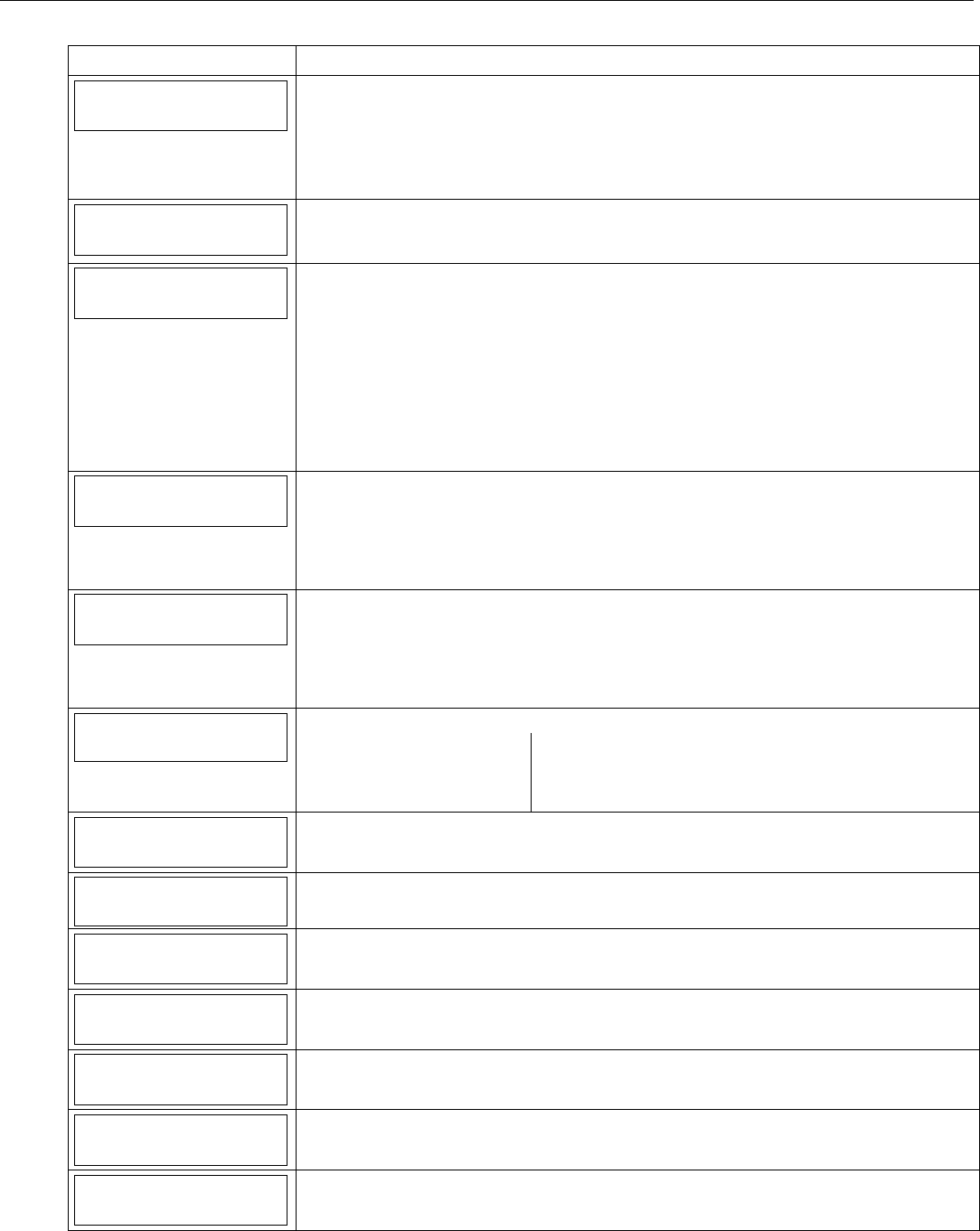
LYNX Touch Installation and Setup Guide
- 35 -
Programming the Control
SCREEN ACTION
Alarm Report Delay
No Delay
Note: This field applies only to the LYNX Touch control.
Select “Alarm Report Delays”. The System scrolls between the following options:
15sec
30sec
45sec
No delay
Swinger Shutdown
2 Reports
Note: This field applies only to the LYNX Touch SIA control.
Select “Swinger Shutdown”, the system toggles between “1 Report” and “2 Reports”.
Abort Window
30sec
Note: This field applies only to the LYNX Touch SIA control.
Select “Abort Window”. The System scrolls between the following options:
15sec
30sec
45sec
SIA The burglary abort window must be set to a minimum of 15 seconds. The sum of the
burglary abort window and the entry delays should not exceed 1 minute.
Note: The LYNX Touch SIA control validates the data entered in this field. If the selection is
not valid the control will emit a single long beep indicating that the selection has been
rejected. The control replaces the selection with the default value “30sec.
First Report Offset
6 Hrs
Select “First Report Offset” for the Test Report. The System scrolls between the following
options:
6 Hrs
12 Hrs
18 Hrs
24 Hrs
Report Frequency
Never
Select “Report Frequency” for the Test Report. The System scrolls between the following
options:
Never
Every Day
Every 7 Days
Every 30 Days
Downloader
Select “Downloader”. The System displays the following options:
Phone Answer Modem Speed
Ans.Machine Defeat Callback Number
Ring Counter Flexible Callback
Number
Phone Answer
Yes
Select “Phone Answer”, the system toggles between “Yes” and “No”.
Modem Speed
Slow
(Future Use)
Ans. Machine Defeat
Yes
Select “Ans. Machine Defeat”, the system toggles between “Yes” and “No”.
Callback Number
Select “Callback Number” and enter callback number on the displayed keypad.
Ring Counter
2
This option only appears if Answering Machine defeat is set to “No”. Enter ring counter (1 –
14 rings) on the displayed keypad.
Flexible Callback
No
Select “Flexible Callback”, the system toggles between “Yes” and “No”.
Number
1
This option only appears if “Flexible Callback” is set to “Yes”. The system scrolls between
options 1, 2 and 3.
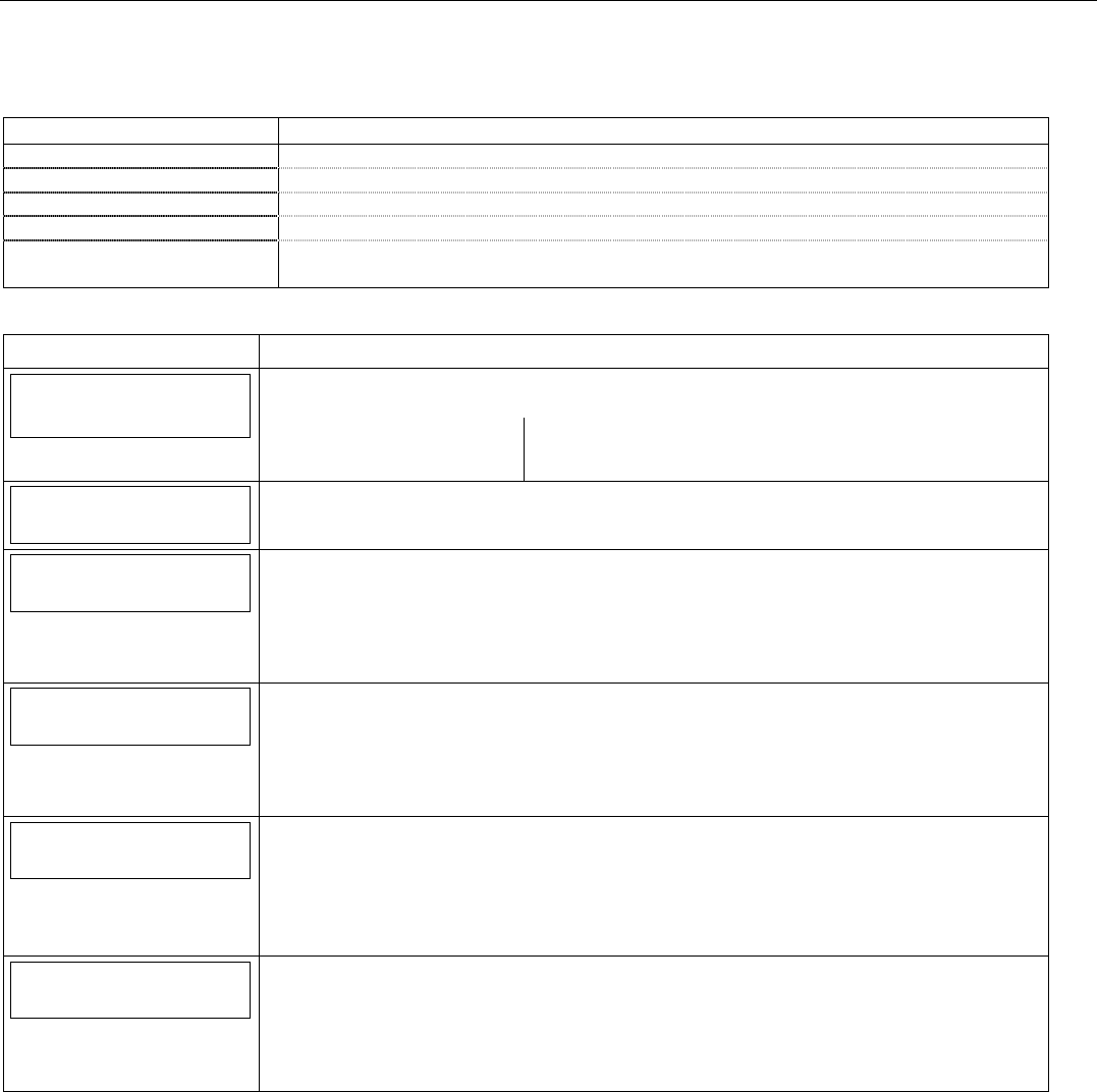
LYNX Touch Installation and Setup Guide
- 36 -
Programming the Control
Sounder
The following system options are programmed in this section:
Option Function
Burglary Alarm Sound Switches the full 110 dB alarm sound for burglary On/Off.
Burglary Alarm Timeout Select the time for timeout of the Burglary Alarm sounder.
Fire Bell Timeout Select the time for timeout of the Fire Alarm sounder.
Arm Confirm Enable sounder “ding” when system is armed via the selected RF device.
Alarm Options Select a limit for the number of times an alarm can sound for a specific zone.
Note: This option does not apply to the LYNX Touch SIA control.
Note: If applicable, preprogrammed defaults for the LYNX Touch Control are shown on the screen unless otherwise noted.
SCREEN ACTION
Sounder
Select “Sounder”
The System displays the following options:
Burglary Alarm Sound Burglary Bell Timeout
Fire Bell Timeout Arm Confirm
Alarm Options
Burglary Alarm Sound
Yes
Select “Burglary Alarm Sound”. The System toggles between Yes* and No:
Burglary Bell Timeout
4 Minutes
Select “Burglary Bell Timeout”. The System scrolls between the following options:
No
4 Minutes
8 Minutes
12 Minutes
16 Minutes
Fire Bell Timeout
4 Minutes
Select “Fire Bell Timeout”. The System scrolls between the following options:
No
4 Minutes
8 Minutes
12 Minutes
16 Minutes
Arm Confirm
None
Note: This option does not apply to the LYNX Touch Control.
Select “Arm Confirm”. The System scrolls between the following options:
None
All RF
RF Key Fob
RF Keypad
Alarm Options
Unlimited
Select “Alarm Options”. The System scrolls between the following options:
Unlimited
1
2
10
Select “Save”.

LYNX Touch Installation and Setup Guide
- 37 -
Programming the Control
System Settings
The following system options are programmed in this section:
Option Function
Entry Delay1/Entry Delay 2 Selects an Entry Delay time in seconds. The system will wait the time entered before
sounding alarm upon entering if system is not disarmed.
Note: The Default values differ for the LYNX Touch and LYNX Touch SIA controls.
Exit Delay Selects an Exit Delay time in seconds for both Entry Delay 1 and 2 Zone Types. The
system will wait the time entered before sounding an alarm if the exit door is left open after
the system has been armed.
Note: The Default values differ for the LYNX Touch and LYNX Touch SIA controls.
Backlight Timeout Enable or disable display backlight turnoff after 30 seconds.
Quick Arm Enables or disables Quick Arm Mode. If enabled, security code is not required to arm the
system. The user simply presses and holds down the AWAY button or ICON and then
selects the ARM button on the displayed keypad to arm the system.
Quick Exit Enables or disables Quick Exit Mode. If enabled allows the user restart the exit delay to
allow entry or exit when the system is armed
Restart Exit Time Enables or disables Restart Exit Time Mode. This option allows the control to restart the
exit delay time after arming in STAY mode by entering the User Code and pressing the
STAY key (if quick arming is disabled) or by pressing the STAY key (if quick arming is
enabled). This option also enables automatic exit delay reset, which resets exit delay if the
entry/exit door is re-opened and closed before exit delay time expires after arming.
Force Bypass Enables or disables Force Bypass Mode. All zones bypassed by this function will be
displayed after the bypass is initiated. The Fire and CO Zones are not bypassed in the
LYNX Touch.
Exit Warning Enables or disables Exit Warning sound. Audible Exit Warning sound consists of slow
continuous beeps until last 5 seconds, when it changes to fast beeps. The warning sound
will end at the termination of exit delay.
Note: This field is not programmable in the LYNX Touch SIA and is always enabled.
Auto Stay Arming Enables or disables Auto Stay Arming Mode. If this feature is enabled and the control panel
has been armed “Armed Away” at the LYNX Touch keypad or RF keypad, the system will
switch to the “Armed Stay” mode if the Exit Time has expired and no exit has been made.
Lack of Usage Notify Enables or disables Lack of Usage Notification feature. If enabled, notifies the central
station if an end user is not operating their security system by sending a System Inactivity
report 654. The report will be sent only to the Primary phone number and only if Contact
ID® format was selected.
Power-Up in Previous Enables or disables Power-Up in Previous Mode feature. When the system powers up
armed, an alarm will occur 1 minute after arming if a zone is faulted. For the LYNX Touch
control any bypassed zones will be unbypassed. For the LYNX Touch SIA any bypassed
zones will remain bypassed.
Display Alarm Cancel Enables or disables display of Cancelled Alarm.
Display Exit Time Enables or disables display of Exit Time.
Cross Zone Delay Sets the maximum amount of time in which two zones must be tripped in an armed system
to send an alarm message to the Central Station. If only one cross zone is tripped during
this time, a trouble message (CID code 380) for that zone is sent to the Central Station.
Cross Zone 1/Cross Zone 2 Select the zones that will be used for Cross Zoning
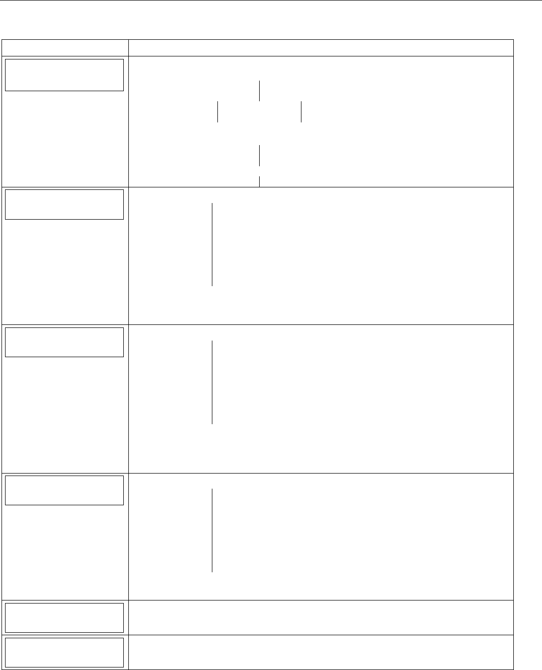
LYNX Touch Installation and Setup Guide
- 38 -
Programming the Control
Note: If applicable, preprogrammed defaults for the LYNX Touch Control are shown on the screen unless otherwise noted.
SCREEN ACTION
System Settings
Select “System Settings”
The System displays the following options:
Entry Delay 1 Entry Delay 2
Exit Delay Backlight Timeout
Quick Arm Quick Exit Restart Exit Time
Force Bypass Exit Warning Auto Stay Arming
Use the down T arrow to scroll to the next page of options. Use the S arrow to return to
the previous page:
Lack of Usage Notify Power-Up In Previous
Display Alarm Cancel Display Exit Time
Cross Zone Delay
Cross Zone 1 Cross Zone 2
Entry Delay 1
30 Seconds
Select “Entry Delay 1”. The System scrolls between the following options:
LYNX Touch LYNX Touch SIA
None 30 Seconds
15 Seconds 45 Seconds
30 Seconds 60 Seconds
45 Seconds 90 Seconds
60 Seconds 2 Minutes
90 Seconds 3 Minutes
2 Minutes 4 Minutes
UL installations: The Entry Delay must be set for a maximum of 45 seconds
SIA: The Entry delay must be set to a minimum of 30 seconds. The sum of entry delay 1 and
the burglary abort window should not exceed 1 minute.
Entry Delay 2
60 Seconds
Select “Entry Delay 2”. The System scrolls between the following options:
LYNX Touch LYNX Touch SIA
None 30 Seconds
15 Seconds 45 Seconds
30 Seconds 60 Seconds
45 Seconds 90 Seconds
60 Seconds 2 Minutes
90 Seconds 3 Minutes
2 Minutes 4 Minutes
UL installations: The Entry Delay must be set for a maximum of 45 seconds
SIA: The Entry delay must be set to a minimum of 30 seconds. The sum of entry delay 2 and
the burglary abort window should not exceed 1 minute. The LYNX Touch SIA default is
“60 Seconds”.
Exit Delay
60 Seconds
Select “Exit Delay”. The System toggles between the following options:
LYNX Touch LYNX Touch SIA
None 45 Seconds
15 Seconds 60 Seconds
30 Seconds 90 Seconds
45 Seconds 2 Minutes
60 Seconds
90 Seconds
2 Minutes
UL installations: Exit Delay must be set for a maximum of 60 seconds
SIA: The Exit Delay must be set to a minimum of 45 seconds.
Backlight Timeout
No
Select “Backlight Timeout”. The System toggles between No and 30 Seconds.
Quick Arm
Yes
Select “Quick Arm”. The System toggles between Yes and No.
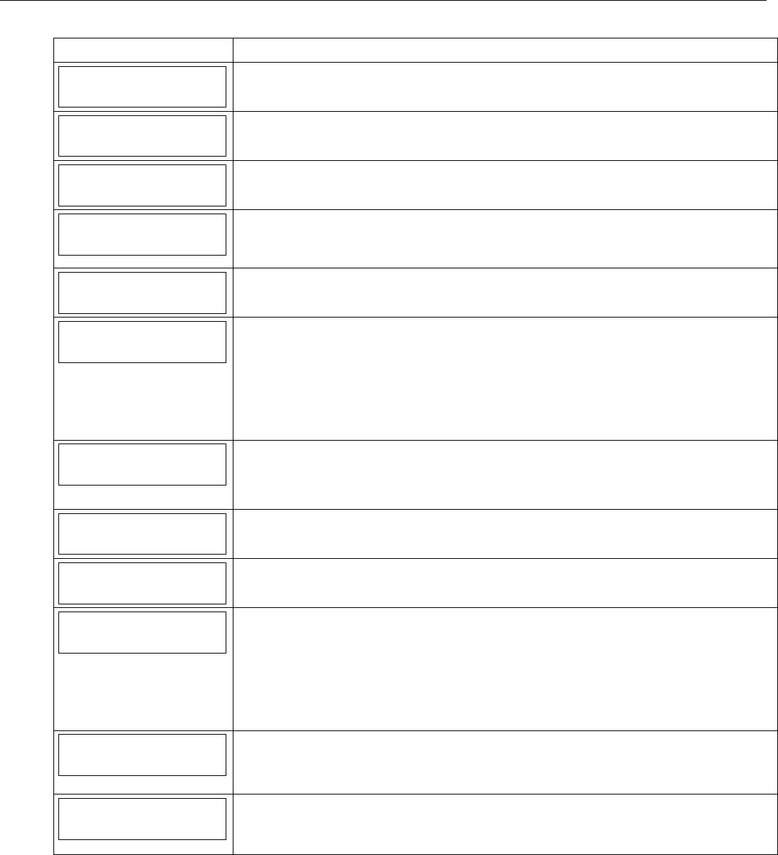
LYNX Touch Installation and Setup Guide
- 39 -
Programming the Control
SCREEN ACTION
Quick Exit
Yes
Select “Quick Exit”. The System toggles between Yes and No.
Restart Exit Time
No
Select “Restart Exit Time”. The System toggles between Yes and No.
SIA: The LYNX Touch SIA default is “Yes”.
Force Bypass
No
Select “Force Bypass”. The System toggles between Yes and No.
UL installations: must be NO (no forced bypass)
Exit Warning
No
Select “Exit Warning”. The System toggles between Yes and No.
Note: This option is not selectable in the LYNX Touch SIA control and is always
enabled.
Auto Stay Arming
No
Select “Auto Stay Arming”. The System toggles between Yes and No.
SIA: The LYNX Touch SIA default is “Yes”.
Lack of Usage Notify
Disabled
Select “Lack of Usage Notify”. The System scrolls between the following options:
Disabled
1 Day
7 Days
27 Days
90 Days
180 Days
365 Days
Power-Up In Previous
Yes
Select “Power-Up In Previous”. The System toggles between Yes and No.
Note: If the previous state was Armed Away or Stay, the system will not respond to sensor changes for
1 minute. This allows time for sensors such as PIRs to stabilize.
UL installations: must be 1 (power up in previous state)
Display Alarm Cancel
No
Select “Display Alarm Cancel”. The System toggles between Yes and No.
Display Exit Time
Yes
Select “Display Exit Time”. The System toggles between Yes and No.
Cross Zone Delay
3 Minutes
Select “Cross Zone Delay”. The System toggles between the following:
None
30 Seconds
1 Minute
90 Seconds
2 Minutes
3 Minutes
4 Minutes
Cross Zone 1
Disabled
Select “Cross Zone 1”. The System toggles between the following:
Disabled
Note: If Cross Zone Delay is enabled the system will display the zones that are programmed with the
following Zone Types: Day/Night, Interior Follower and perimeter.
Cross Zone 2
Disabled
Select “Cross Zone 2”. The System toggles between the following:
Disabled
Note: If Cross Zone Delay is enabled the system will display the zones that are programmed with the
following Zone Types: Day/Night, Interior Follower and perimeter.
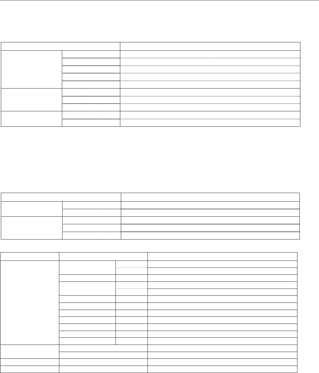
LYNX Touch Installation and Setup Guide
- 40 -
Programming the Control
Communications Diagnostics
Communications Status – The system provides a status of the IP or GSM communications paths and
performs a self-test of the AES encryption algorithm as follows:
Message Meaning
GSM: OK Normal; No fault. (IP or GSM)
Fault Reported! No network connectivity and fault time has expired. (IP or GSM)
Not Connected No network connectivity over IP and fault time has NOT yet expired.
Not Registered! No network connectivity over GSM and fault time has NOT yet expired.
No Physical Link No network connectivity over IP and fault time is set to 0.
Encryption: AES Passed! Test successful.
AES Failed! Test failed.
No Encryption! No encryption algorithm set.
Alarmnet Registration: Registered Communication Device is Registered with AlarmNet.
Not Registered Communication Device is not Registered with AlarmNet.
Ethernet Information – Displays IP information, if IP communication path is enabled.
Physical Link: Indicates status of the physical connection to the internet.
DHCP: DHCP (Dynamic Host Configuration Protocol) indicated server is performing satisfactorily.
NIC IP Address: Displays the IP address assigned to this device
Subnet Mask: Displays the 32-bit address mask used to indicate the portion (bits) of the IP address that is
being used for the subnet address.
Gateway IP Address: Displays the IP address assigned to the Gateway.
DNS Server IP Address: Displays the IP address assigned to the DNS (Domain Name System) server.
Message Meaning
Physical Link 10 Mbps or 100 Mbps Link speed of physical connection
Bad No physical connection
DHCP OK DHCP address resolved
Bad DHCP address not resolved
Off DHCP disabled
GSM Information – Displays GSM information if GSM communication path is enabled.
Status Message Meaning
GSM Registered Cell Registration: Home Registered Home
Roaming Registered Roaming
Primary RSSI: -xxdBm* Primary Site RSSI level in dBm
GPRS: Yes GPRS Service availability
No GPRS is not available
Country: xxx Country Code
Network: xxx Network Code
LAC xxxxx Local Area Code
Cell: xxxx Base Station ID
Base Station: xx Base Station Antenna Sector
Channel: xxx Control Channel in use
Second Site RSSI: -xxdBm* Secondary Site RSSI level in dBm
GSM Not Registered Searching For Coverage! Searching for cell network.
SIM Error! No SIM card present or SIM card faulty
Cell Registration: SIM Not Active SIM is not activated
Cell Registration: Not Registered Not registered with cell network
* RSSI = Communications Module’s Signal Level. Displayed in dBm, where:
xx = -01 to -93 Indicates Good signal level
xx = -94 to -95 Indicates Poor signal level. Unit should be relocated for better signal level.
xx = -96 (and lower) Indicates fail signal level. Move unit for better signal level. If “FAIL” condition persists, do not install.
LYNX Touch Installation and Setup Guide
- 41 -
Programming the Control
Communications ID Numbers – Displays programmed SIM card information
Message Meaning
MAC: xxxxxxxxxxxx MAC Address indicates the unique identification number
MAC CRC: xxxx MAC CRC number
SCID:* xxxxxxxxxxxxxxxxxxxx Displays the ID number assigned to the installed SIM card (SCID)
IMEI:* xxxxxxxxxxxxxxx Displays the ID number assigned to the installed GSM module.
* Displayed if GSM communication path is enabled.
Test Communications – Performs network diagnostics and sends test alarms to AlarmNet. The following
tests are available depending on the type of communications module installed.
Test Ethernet
This test is available if IP communication path is enabled. The network diagnostic process tests the integrity of the links
between the LYNX Touch and the various connection points of AlarmNet Control that are known as “Redirectors”. If a
physical link is detected and is ready, the following diagnostics are performed.
Testing Gateway… Traces the connection to the Gateway and displays the following:
Testing Gateway – Successful! A successful trace to Gateway. OR
Testing Gateway – Failed! Failed to reach Gateway.
Testing Redirector * Sequentially traces the connection to Redirector 1, 2 and 3 at AlarmNet Control. The following will be
displayed.
Redirector * – Service OK Service at AlarmNet Control on Redirector 1, 2 or 3 is functioning. OR
Redirector * – Failed Error occurred on Redirector 1, 2 or 3.
* = Number of the director being tested is displayed
A summary of the tests is displayed after Redirector 3 is tested. The example shows that the tests of all three
connection points, or Redirectors, were successful. If an error occurred at any point, the summary will display
“Failed” next to the faulty Redirector.
Redirector 1 – Service OK
Redirector 2 – Service OK
Redirector 3 – Service OK
If no physical link is detected, the test is aborted and one of the following is displayed:
No Physical Link No physical link is detected.
Link Not Ready There is a link but it is not ready (address not resolved).
Send Any
If both IP and GSM communication paths are enabled and the LYNX Touch is registered, a Test alarm is sent over IP path. If
that is not successful, it sends the alarm over GSM path and the following message is displayed: Test Message Sent
If the device is not registered, the following is displayed: Test Message Failed – Not Registered
Send GSM Message
If GSM communication path is enabled and the LYNX Touch is registered, a Test alarm to AlarmNet over the GSM path. The
following message is displayed: Test Message Sent
If the device is not registered, the following message is displayed: Test Message Failed – Not Registered
Send Ethernet Message
If IP communication path is enabled and the LYNX Touch is registered, a Test alarm to AlarmNet over the IP path. The
following message is displayed: Test Message Sent
If the device is not registered, the following message is displayed: Test Message Failed – Not Registered
Setup Communication – Performs registration of the LYNX Touch and its associated communication
module with AlarmNet updates configuration files or reset factory defaults.
Registering the LYNX Touch
Once the LYNX Touch is initialized and a communications module is programmed, it must be registered to
enable the account. Upon completion of the registration process, the LYNX Touch transmits a registration
message and receives a registration validation indicating that the account is now enabled. Wait for the
“Registration Success” message to appear, regardless of which registration method is used.
You can register the communications module by one of the following methods:
• Through the AlarmNet Direct website
• By Phone
• Through the LYNX Touch Diagnostics
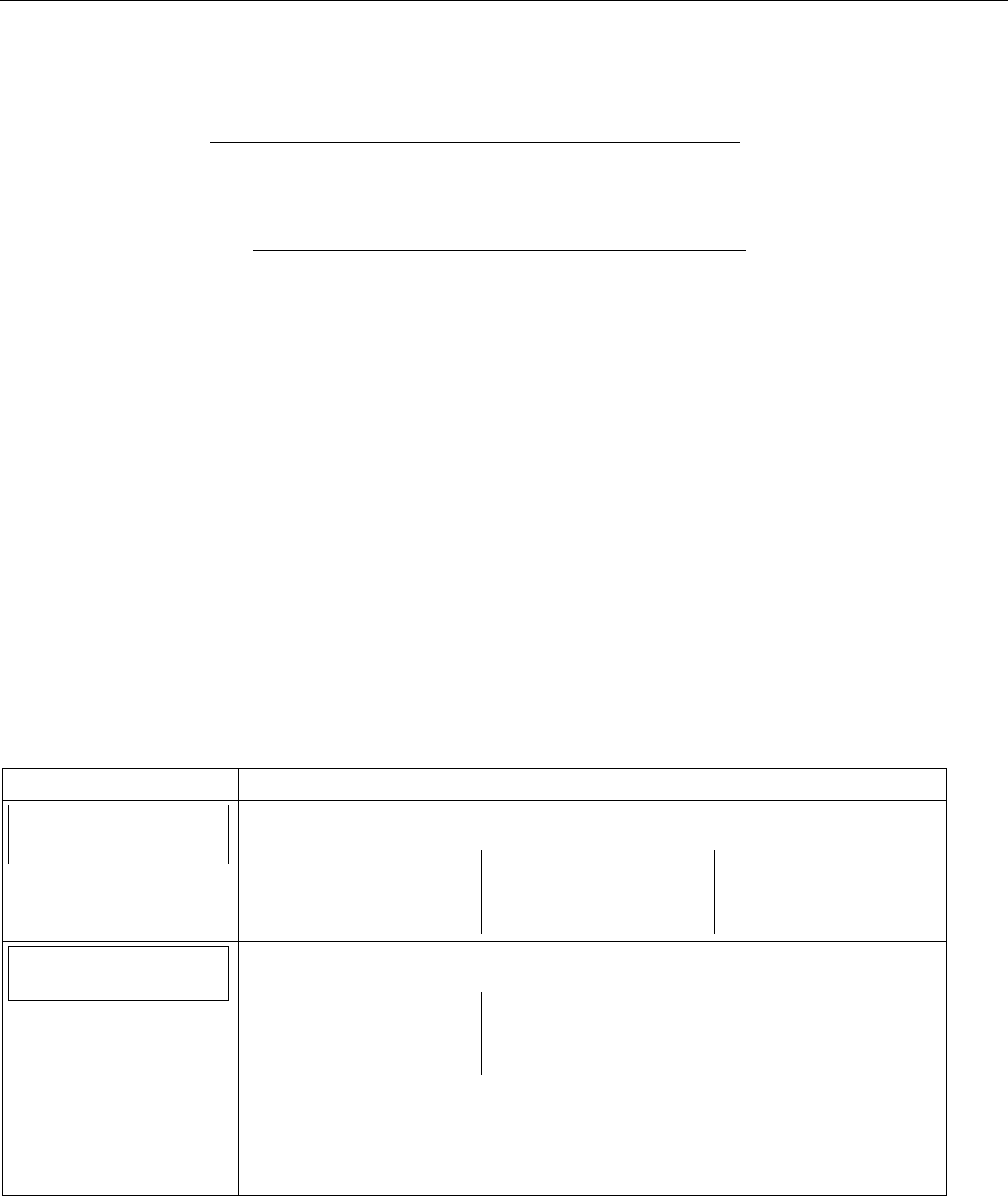
LYNX Touch Installation and Setup Guide
- 42 -
Programming the Control
Register through AlarmNet Direct Website
If you have programmed the communications module through AlarmNet Direct, you must then transfer the
data to the module, and register the module.
To do this, please go to: https://services.alarmnet.com/AlarmNetDirect/userlogin.aspx.
Log in and follow the on-screen prompts.
If you are not signed up for this service, click on “Dealer Signup” from the login screen to gain access to the
Honeywell web-based programming.
Dealer Sign-Up Direct Link: https://services.alarmnet.com/AlarmNetDirectP_Sign-Up.
You will be instructed how to proceed upon completing the sign-up form. Only one sign-up per dealer is
required. Once an initial user is established, additional logins may be created by that user.
Please have the following information available when programming the device:
1. Primary City ID (two-digit number)
2. Primary Central Station ID (two-digit hexadecimal number)
3. Primary Subscriber ID (four-digit number)
4. MAC ID and MAC CRC number (located on outside of box and on label inside module – location to be
confirmed).
Once module is registered, you may log out of the AlarmNet Direct website.
Register by Phone
You can register the module by calling the AlarmNet Technical Assistance Center (TAC) at 1-800-222-6525.
You will need the following information:
• MAC number (found on the label).
• Subscriber information (provided by the central station), including a city code, CSID, and a subscriber
ID.
• When instructed to do so, select Register Device in the LYNX Touch Diagnostics to complete the
registration.
Register through LYNX Touch Diagnostics
You can register the module using the LYNX Touch Diagnostics by the following the following procedure.
SCREEN ACTION
Comm. Diagnostics
1. Select “Comm. Diagnostics” The System displays the following options depending upon
the communication device that is installed:
Communication
Status
Ethernet
Information
GSM
Information
Communication
ID Numbers
Test
Communication
Setup
Communication
Setup
Communication
2. Select “Setup Communication”. The System advances to the Registration screen and
the following options are displayed:
Register
Device
Register Device
With PIN
Update
Server
Factory
Defaults
3. Select “Register Device”. The registration message is sent and the unit waits
for the acknowledgement. (Refer to the table below for applicable
registration messages.)
Note: Register Device can be cancelled by selecting “Cancel”. The registration process is
aborted and the message Registration Cancelled! is displayed.
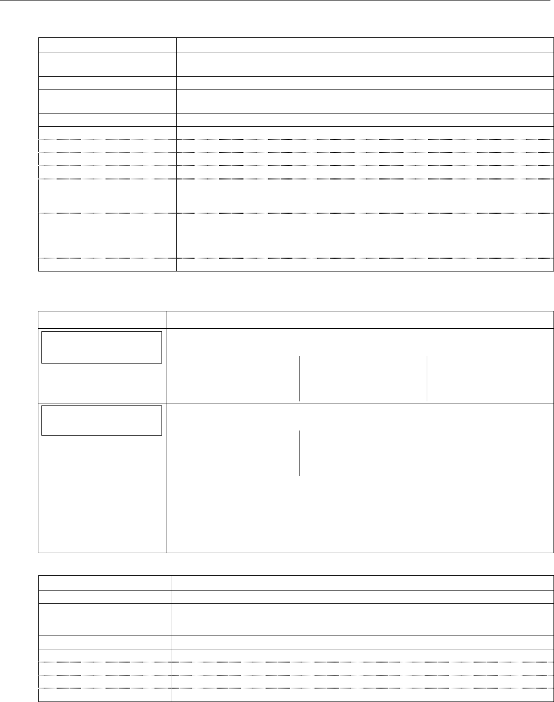
LYNX Touch Installation and Setup Guide
- 43 -
Programming the Control
During the registration process the following messages may be displayed:
Message Meaning
Getting Configuration File… The configuration file is obtained from AlarmNet if the module was programmed through
AlarmNet Direct or a previously programmed module was defaulted.
Registering… The registration message is sent and the unit is waiting for the acknowledgement.
Registration Successful! The module is registered and is now in full service and available for alarm reporting to the
central station.
Registering – Try Later! Error Message indicates the module is busy.
Registration Failed! Error message followed by one of the messages below:
Invalid Configuration! Indicates the configuration is invalid.
Timed Out. Displayed if no response to the registration request is received.
Central Station Database Full. Indicates CS database has more than 1000 subscribers.
Primary Sub ID Bad. Indicates the city, central station, or customer number for the labeled account is not
accepted. The ID information was either entered incorrectly, or the central station failed to
pre-authorize programmed ID numbers with AlarmNet customer service.
Primary ID – Need PIN. Indicates the city, central station, or customer number for the labeled account is not
accepted. The ID information was either entered incorrectly, or the central station failed to
pre-authorize programmed ID numbers with AlarmNet customer service. See the Register
Device With PIN section.
Account Disabled. Displayed if the account is disabled in AlarmNet.
Register Device With PIN
This procedure is used to replace one LYNX Touch module with another.
SCREEN ACTION
Comm. Diagnostics
1. Select “Comm. Diagnostics” The System displays the following options depending upon
the communication device that is installed:
Communication
Status
Ethernet
Information
GSM
Information
Communication
ID Numbers
Test
Communication
Setup
Communication
Setup
Communication
2. Select “Setup Communication”. The System advances to the Registration screen and
the following options are displayed:
Register
Device
Register Device
With PIN
Update
Server
Factory
Defaults
3. Select “Register Device With PIN”. Enter a 4-digit alphanumeric PIN number
(provided by your central station, your dealer or an authorized AlarmNet
representative) on the displayed keypad then select “Done”. (Refer to the
table below for applicable registration messages.)
Note: Register Device With PIN can be cancelled by selecting “Cancel”. The registration
process is aborted and the message Registration Cancelled! is displayed.
During the registration process the following messages may be displayed:
Message Meaning
Registering… The registration message is sent and the unit is waiting for the acknowledgement.
Registration Successful! The PIN number is valid and module is registered and is now in full service and available
for alarm reporting to the central station. The old module is unregistered. Additionally,
AlarmNet sends a substitution alarm to the central station.
Registering – Try Later! Error Message indicates the module is busy.
Registration Failed! Error message followed by one of the messages below:
Invalid Configuration! Indicates the configuration is invalid.
Timed Out. Displayed if no response to the registration request is received.
Primary ID – Need PIN. Indicates PIN that was entered is invalid.
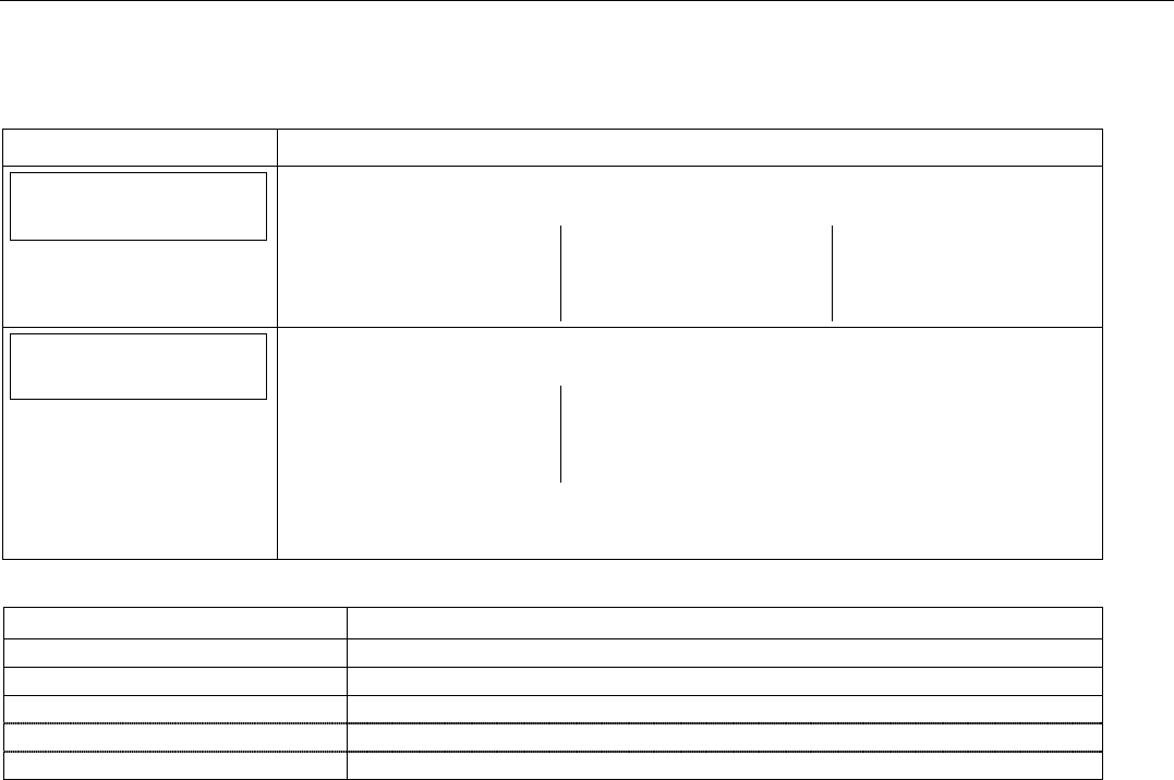
LYNX Touch Installation and Setup Guide
- 44 -
Programming the Control
Update Server
This procedure is used to upload the Configuration File to the Server.
SCREEN ACTION
Comm. Diagnostics
1. Select “Comm. Diagnostics” The System displays the following options depending upon
the communication device that is installed:
Communication
Status
Ethernet
Information
GSM
Information
Communication
ID Numbers
Test
Communication
Setup
Communication
Setup
Communication
Yes
2. Select “Setup Communication”. The System advances to the Registration screen and
the following options are displayed:
Register
Device
Register Device
With PIN
Update
Server
Factory
Defaults
3. Select “Update Server” and select “Yes” when the confirmation screen appears. The
device uploads its entire configuration file to the server. Selecting “No” will cancel the
operation. (Refer to the table below for applicable registration messages.)
During the upload process the following messages may be displayed:
Message Meaning
Updating Root File… The root file is being uploaded.
Programming Done Indicates the root file has been successfully uploaded.
Updating Configuration – Try Later! Error message indicates the module is busy
Cannot Upload – Try Later! Error message indicates the communication path(s) is not available.
Update Root File – Failed! Error message indicates an error while uploading root file..
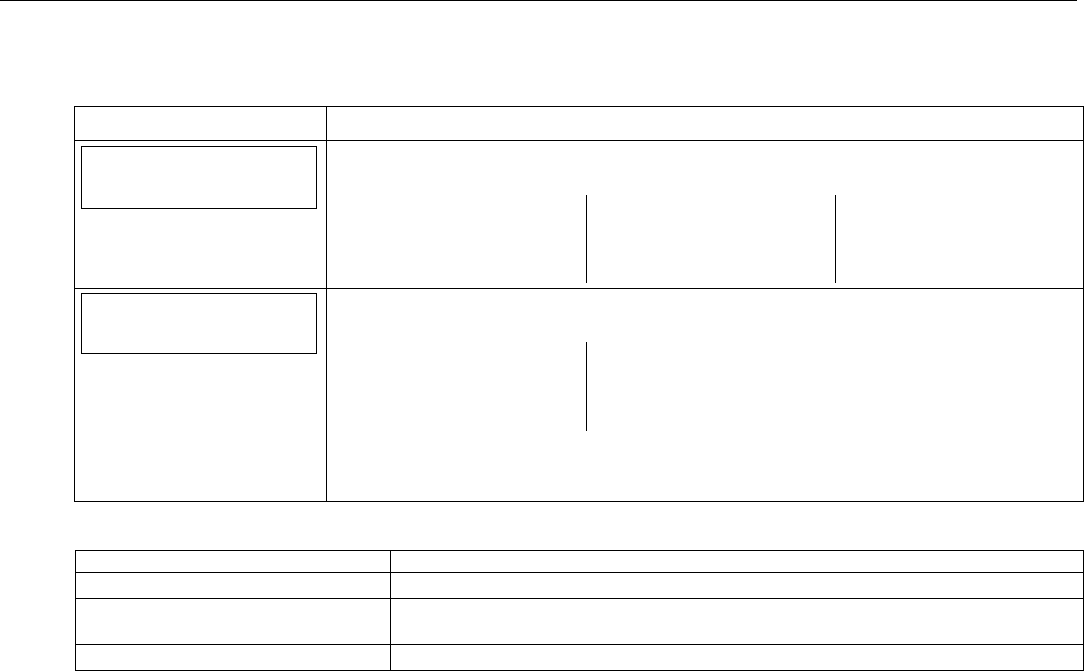
LYNX Touch Installation and Setup Guide
- 45 -
Programming the Control
Factory Defaults
This procedure resets the programming options to factory-default values.
SCREEN ACTION
Comm. Diagnostics
1. Select “Comm. Diagnostics” The System displays the following options depending upon
the communication device that is installed:
Communication
Status
Ethernet
Information
GSM
Information
Communication
ID Numbers
Test
Communication
Setup
Communication
Setup
Communication
2. Select “Setup Communication”. The System advances to the Registration screen and
the following options are displayed:
Register
Device
Register Device
With PIN
Update
Server
Factory
Defaults
3. Select “Factory Defaults” and select “Yes” when the confirmation screen appears. The
device is reset to factory default values. Selecting “No” will cancel the operation. (Refer
to the table below for applicable registration messages.)
The following messages may be displayed:
Message Meaning
Default Configuration – Successful! Indicates all programmed values are reset to the original factory settings.
Default Configuration Failed –
Access Denied
Error message indicates the device does not have local programming access.
Default Configuration – Try Later! Error message indicates the module is busy.

LYNX Touch Installation and Setup Guide
- 46 -
Remote Programming/Control (Downloading)
General Information
The control panel can be remotely programmed from an IBM-compatible Personal Computer (PC), Compass
Downloader, a HAYES compatible Modem or via a capable GSM or IP Communications Module. When
connected to the COMPASS Downloader – “SERVICE UPDATE” appears on touch screen.
UL Downloading may only be performed if a technician is at the site.
Multiple security levels protect remote programming against compromise by attempts to defeat the system.
1. Security Code Handshake: A download ID code is verified for authenticity before connection is
established.
2. Site-Initiated Remote Programming: The installer initiates downloading by selecting the “Initiate
Download” button on the Installer programming screen.
3. Station-Initiated Remote Programming: The operator calls the site from your office to initiate the
download call. The Control hangs up and then calls back the PC via the preprogrammed telephone
number. The unit can then be uploaded, downloaded, or controlled from your office.
4. Data Encryption: Data passed between the PC and the Control is encrypted for security so that it is
very difficult for a foreign device tapped into the phone line to take over communication and substitute
system-compromising information.
Equipment required to download to a system at the premises
• Compass Downloader for Windows (at revision level supporting LYNX Touch).
Flexible Callback: If enabled in Installer Programming, the download operator can temporarily change
the last 1, 2, or 3 digits (depending on selection) of the call back number. This allows the control to call back
a computer other than the one programmed, which may be helpful at times of high computer traffic.
Remote Programming Information
If using Remote Programming, the LYNX Touch must be connected to the telephone line, GSM Cellular or
to the Internet, as applicable.
The downloading system can perform many functions when in communication with the Control. Besides
uploading and downloading, the status of the system can be observed and various commands can be
initiated, as follows:
• Arm the system in the away mode; disarm the system.
• Bypass a zone.
• Force the system to accept a new program download.
• Shut down communication functions (for nonpayment of monitoring fees in an owned system).
• Shut down all security system functions (for nonpayment for a leased system).
• Inhibit local keypad programming (prevents account takeover).
• Command the system to upload a copy of its resident program to the office.
• Set the time
• View/Modify
• Read: arming status, AC power status, lists of faulted zones, bypassed zones, zones currently in alarm,
zones currently in trouble, and RF sensors with low battery conditions; read control’s time.
Notes: (1) After the control and the PC have established valid communication, “Service Update” will be displayed on the
LCD.
(2) The detailed operation of the download functions is covered in the installation instructions for the Compass
Downloader for Windows.

LYNX Touch Installation and Setup Guide
- 47 -
Remote Programming/Control (Downloading)
Remote Programming Advisory Notes
• A copy of the program downloaded may be printed using the IBM PC-compatible computer’s internal
report generator, when an optional printer is connected (consult your PC manual for proper printer and
connections).
• The approximate time for program upload or download for a complete program is shown below:
Communication
Method
Approx.
Time
PSTN 380 secs.
GSM 75 secs.
IP 30 secs.
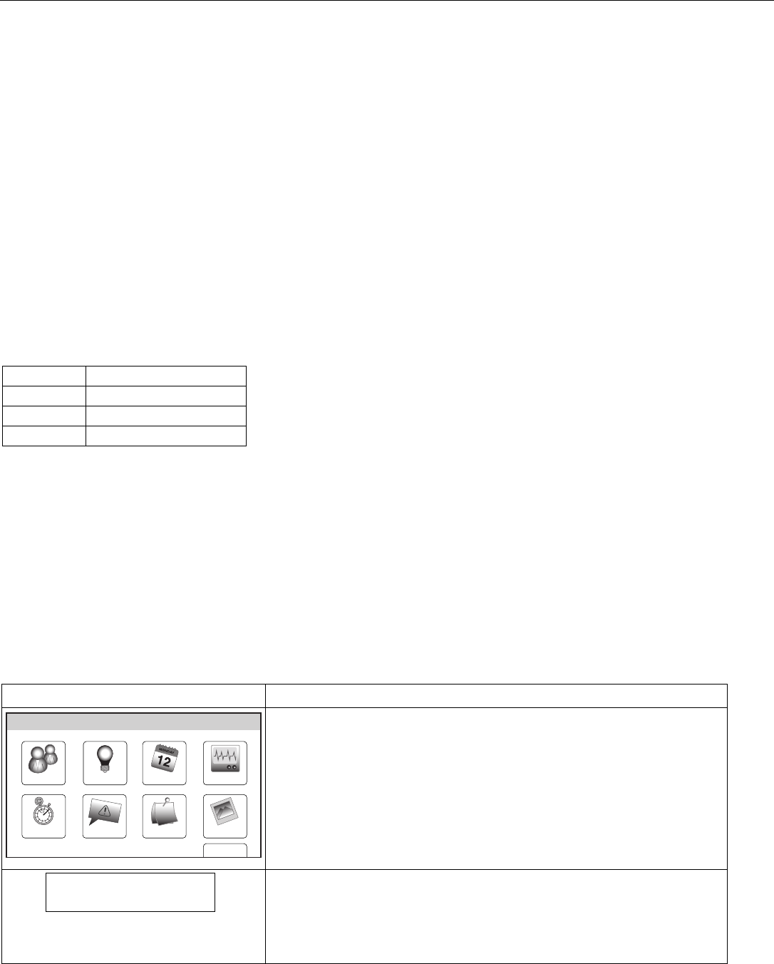
LYNX Touch Installation and Setup Guide
- 48 -
System Operation
Key/Touchscreen Operation
The keys and touchscreen allows the user to arm and disarm the system, and perform other system
functions, such as bypassing zones. Zone and system conditions (ALARM, trouble, bypass) are displayed on
the display. When an alarm occurs, console sounding and external sounding will occur, and the zone(s) in
alarm will be displayed on the display. Pressing any key will silence the keypad sounder for 10 seconds (only
once). Disarming the system will silence both console and external sounders. When the system is disarmed,
any zones that were in an alarm condition during the armed period will be displayed (memory of alarm). To
clear this display, simply repeat the disarm sequence by pressing the OFF key and entering the Security
Code. The console also features chime annunciation, and three panic key icons for silent, audible, fire or
personal emergency alarms. These keys can notify the central station of an alarm condition, if that service
is connected.
Panic Key/Icons
There are three panic key icons that, if programmed, are displayed on the virtual keypad when the “PANIC”
key is depressed for four seconds. The panic key screen will timeout if a selection is not made within ten
seconds. The keys can be used to manually initiate alarms and send a report to the central station. Each can
be individually programmed for 24-hour silent, audible, personal or fire emergency responses. The panic
function is activated when the respective keys is pressed. The panic functions are identified by the system as
follows:
Zone Function
95 Fire Emergency
96 Medical Emergency
99 Police Emergency
Important: For the silent panic functions to be of practical value, the system must be connected to a central station.
Security Codes
Installer Code
The installer programs the 4-digit Installer Code initially as part of the programming procedure. The
factory default Installer Code is 4-1-1-2, but may be changed in the Installer Code programming
field. The Installer Code is the only code that allows entry into Installer Programming mode.
Master Code
In normal operation mode, the Master Code is used to enter the 4-digit User Security Codes.
Enter/change the Master code by installer.
The factory default Master Code for the LYNX Touch Control is set to 1-2-3-4. The Master Code is used to
enter the 4-digit User Security Codes.
SCREEN ACTION
Slide ShowDate Time
Ready To Arm
Events
Back
Reminders
TestSchedulesDevicesUsers
5000-100-070-V0
1. After entering the User Tools/Programming Menu, select the “Users” icon
on the User Menu screen. The system displays the User Code
Programming screen
Master ****
2. Select “Master”, then select “Edit”.
3. Enter a new four-digit Master Code on the displayed keypad The system
will display the new code on the left side of the screen.
4. Select “Done” when you are finished.
5. The system returns to the User Code Programming screen.

LYNX Touch Installation and Setup Guide
- 49 -
System Operation
Secondary User Codes
In normal operation mode, the Master Security Code can be used to assign up to 14 secondary 4-digit
security codes, including a Babysitter Code and a Duress Code. The Master Code can also be used to remove
secondary codes from the system (individually). Refer to the LYNX Touch User Manual for additional
information.
Security Code Notes
• The Master and Secondary security codes permit access to the system for arming, disarming, etc.
• The Installer Code can disarm the system only if it was used to arm it. In addition, the Installer Code cannot
disarm the system if it was armed by pressing and holding a Quick-Arm button.
• The Babysitter Code can disarm the system only if it was used to arm it. In addition, the Babysitter Code cannot
disarm the system if it was armed by pressing and holding a Quick-Arm button.
• Duress code sends a special code to the monitoring station when used to perform any system operation. Instruct
users to be careful not to use this code for normal usage.
• Opening/closing reports are sent for the Installer Code, with the appropriate subscriber number. Master Code and
set of secondary user codes are sent as Nos. 02 and 03–14, respectively, in Contact ID® format (with the
appropriate user number).
LYNX Touch Installation and Setup Guide
- 50 -
System Operation
“Follow Me” System Announcement Feature
This feature allows the LYNX Touch to deliver a voice system message to the user phone numbers
programmed by the installer. The LYNX Touch will first transmit reports to the Central Station and after
receiving its kiss-off the system will dial the user phone numbers and begin transmitting the welcome
message “System Message, Press Star to Play”. The system will dial the user phone numbers a maximum of eight
times.
The “Follow Me” System announcements feature is only supported if PSTN line is available. The
announcements are individually sent to the User 1 and/or User 2 phone numbers which are programmed as
Phone 1 and Phone 2 respectively in the Reporter Programming section. System Follow Me announcements
are triggered by a system event that belongs to one of the Event Groups enabled by Installer individually for
User 1 and User 2. The groups are listed below.
• All Bypassing actions by a user
• Any Open/Close (arming/disarming status changes)
• Any Alarms
• Any Alarm Restores
• Alarm Cancel by the user
• Any System Troubles
• Any Test
• Non-security Events
If User 1 does not press a “*” key, LYNX Touch will hang up and will redial the User 1 number in 20
seconds. The control will make eight attempts before unsuccessfully ending the System “Follow Me” session
and erasing all the events in the User 1’s queue. The next call will be triggered by a new event from the
Event Group enabled for User 1.
If User 1 presses a “*” key, LYNX Touch will play back a sequence of System “Follow Me” announcements
from the User 1’s queue in chronological order starting with the oldest one. The announcements will
include “End of Message” at the end of the “Follow Me” announcements.
If a “*” key is pressed again during playback or within 15 seconds following the end of the playback, the
control will repeat the sequence. Otherwise the system will hang up, successfully ending the System “Follow
Me” session. Because the “*” key was pressed LYNX Touch will not redial the User 1 again. The next call
will be triggered by a new event from the Event Group enabled for User 1.
Note: The follow me system announcement will be terminated if any other event requires the system to send a report to the
Central Station. Once the PSTN line is available the session will be resumed and the control will again make up to 8
delivery attempts.
Follow Me Event Triggers Follow Me
Announcement Follow Me Event Triggers Follow Me
Announcement
AC Loss AC Loss Keypad Panic Panic Alarm
Audible Panic Panic Alarm Manual Test System Test
Automatic Disarmed Disarmed Medical Alarm Emergency Alarm
Battery Failed Under Load System Low Battery Opening Keyswitch Disarmed
Burglary Zone Bypass Zone ** Bypassed Perimeter Alarm Perimeter Alarm
Carbon Monoxide Detected Carbon Monoxide Alarm Remote Disarm Disarmed
Disarmed From AWAY or STAY Disarmed RF Sensor Lost System Trouble
Emergency Alarm Emergency Alarm Sensor Low Battery or Tamper Sensor Trouble
Entry/Exit Alarm Perimeter Alarm Silent Burglary Silent Burglary
Exit Error Alarm (zone) Perimeter Alarm Siren Tamper Tamper Alarm
Expansion Module Tamper Tamper Alarm System Inactivity No Check In
Expansion Module Failure System Trouble System Low Battery System Low Battery
Expansion Module Tamper Alarm Tamper Alarm Water Leakage Alarm Auxiliary Alarm
Expansion Module Tamper Trouble Tamper Alarm Zone Bypass Zone ** Bypassed
Fire Alarm Fire Alarm Zone Tamper (Alarm) Tamper Alarm
Fire Trouble System Trouble Zone Trouble System Trouble
Interior Alarm Interior Alarm
** = Zone Number

LYNX Touch Installation and Setup Guide
- 51 -
System Operation
“Follow Me” Reminder Feature
This feature allows the user to schedule a time driven message. When activated, the system will dial the
User 1 and/or User 2 phone numbers, which are programmed as Phone 1 and Phone 2 respectively by the
installer (in the Reporter Programming section), and deliver a recorded message. The LYNX Touch will
immediately begin transmitting the voice message and will repeat the message for 45 seconds. If the
message has timed out, the system will redial the programmed number a maximum of seven additional
times or until it is acknowledged. Pressing any key on the LYNX Touch keypad will terminate (acknowledge)
both the “Follow Me” reminder and the local reminder announcements.
Notes: (1) This feature is only supported if it has been programmed.
(2) The follow me reminder will be terminated if any other event requires the system to dial out, however, delivery of
the local schedule reminder message will continue.
(3) If a Central Station report must be sent, the “Follow Me” Reminder message will be suspended. Once the PSTN
line is available the session will be resumed and the control will again make up to 8 delivery attempts.
Remote Phone Control Feature
The remote phone control feature, which must be enabled, allows the user to access the security system from
any off-site touch-tone telephone. The control will pick up the incoming call, based on the specified ring
count, and will announce “SYSTEM ENTER CODE” every three seconds for the next nine seconds. During
this period the panel will wait for a valid User Code to be entered. If a valid User Code is not entered or the
nine second period expires a modem tone will be generated for remote programming (Compass
Downloading). If a valid User Code has been entered, the control will announce the current system status
and/or beeping sounds. Refer to the User Guide for additional information regarding this feature.
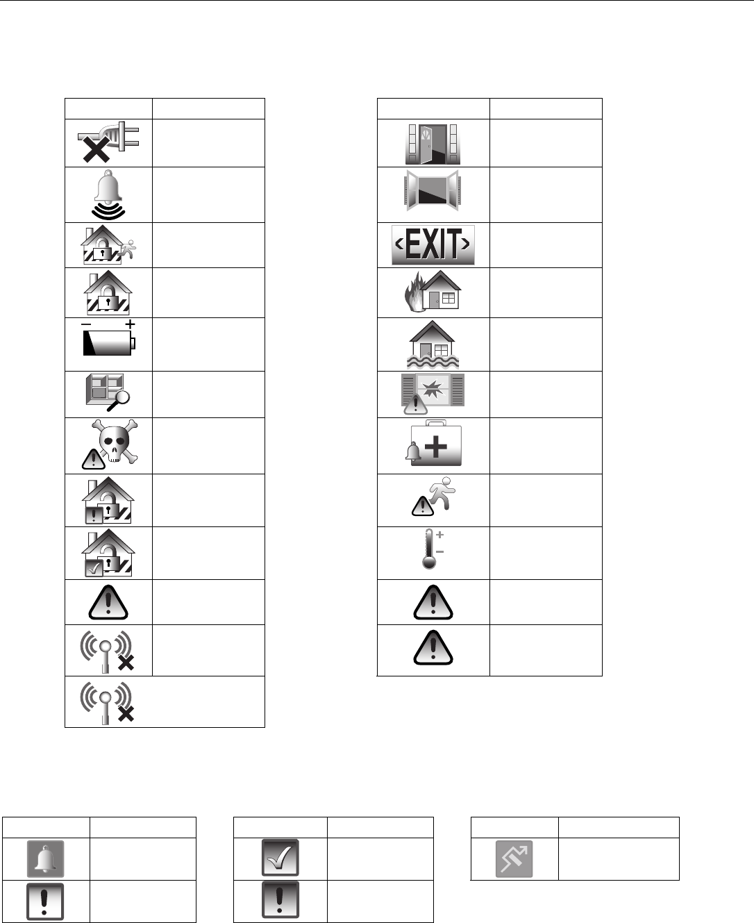
LYNX Touch Installation and Setup Guide
- 52 -
System Operation
System Displays
The following icons will be displayed on the Home screen along with specific zone status information
(if applicable) to indicate system status.
DISPLAY DEFINITION DISPLAY DEFINITION
AC Loss
Door Open
Alarm
(intrusion)
Window Open
Armed Away
Exit Active
Armed Stay
Fire
Battery Low
Flood
Check Zones
Glass Break
CO Alarm
Medical Alarm
Disarmed Not
Ready to Arm
Motion
Disarmed
Ready to Arm
Temperature
90 RF Jam
Cover
Tamper
94 Phone
Line Cut
Reporter
Failure
103 Comm.
Trouble
Zone Status Displays
The following icons will be displayed on the Zone Status screen along with specific zone status information
when a zone has been Faulted, Bypassed or in Alarm.
DISPLAY DEFINITION DISPLAY DEFINITION DISPLAY DEFINITION
Alarm
Ready
Bypass
Fault (Yellow)
Trouble (red)
LYNX Touch Installation and Setup Guide
- 53 -
System Operation
UL Audio alarm verification has not been evaluated by UL.
Audio Alarm Verification (Two-Way Voice Feature)
This feature allows the central station operator to listen, talk to or conduct a two-way conversation with an
individual(s) at the premises. It also assists the operator in gathering information about the nature and
location of the alarm that may be helpful in responding to police and fire departments. All LYNX Touch
control panels are capable of supporting the Two-Way Voice feature. The LYNX Touch does not make system
announcements when the Two-Way voice feature is active.
Activation
Fire and CO alarms will prevent the LYNX Touch from starting an AAV session. A new Fire or CO alarm will
end an AAV session that is in progress.
The LYNX Touch sends the “alarm message” followed by a “Listen-in-to-Follow message” (Contact ID® code
606) to the Central Station. The Listen-in-to-Follow message causes the Central Station’s digital receiver to
temporarily hold the phone line for approximately 1-minute. When the LYNX Touch receives the “kissoff”
from the central station, indicating that the alarm message has been received, the Two-Way Voice (AAV)
feature is activated in the (default) “Listen Mode” and sirens and keypad sounds are discontinued. The
LYNX Touch transmits a beep acknowledgment to the Central Station, once per second. The beep alternates
between two tones and indicates that the LYNX Touch is waiting for a session command from the Central
Station operator. Once a command is issued the beep acknowledgement is discontinued, however, if a
command is not issued within two minutes the system will “time out” and the call will be terminated.
Operator Commands
The Central Station operator begins the session, which last 5 minutes, by entering one of the valid AAV
commands shown in the table below. The session may be extended 5 minutes, without changing the
operating mode, by pressing the [7] key on the touch-tone phone. Selecting another operating mode also
resets the session an additional 5 minutes. During the last minute of the 5 minute, session, the LYNX
Touch generates two beeps every 30 seconds to alert the Central Station operator that the session is about to
time out. The Central Station operator may then extend the session by pressing the [7] key on the touch-tone
phone. If the session is not extended the phone line is disconnected, and the session is ended. Sessions may
be ended at any time by pressing the [9] key on the touch-tone phone. The AAV modes are described as
follows:
Note: When entering AAV commands make sure the Central Station receiver has been disconnected from the phone
line, otherwise AAV commands may not go through.
Key Function
1 Talk Mode: Pressing the [1] key on the touch tone phone, enables one-way voice communication from the
central station to the violated premises, and allows the operator to talk communicate through the LYNX
Touch speaker. In this mode the ARMED (red) and READY (green) LEDs blink alternately.
2 VOX (Voice) Mode: Pressing the [2] key on the touch-tone phone, enables two-way voice communications
between the central station and the violated premises. In this mode the ARMED (red) and READY (green)
LEDs blink alternately.
3 Listen Mode: Pressing the [3] key on the touch-tone phone, enables one-way audio from the violated premises
to the central station. The Listen Mode is the start up default mode of the voice feature and allows the
operator to listen through the LYNX Touch microphone. This mode does not affect the existing LED pattern.
7 Extends the session 5 minutes without changing its operating mode.
9 Ends the session and disconnects the phone line.

LYNX Touch Installation and Setup Guide
- 54 -
System Operation
Event Log
The LYNX Touch Series event log is capable of recording and displaying up to 128 system events. The type
of events that can be recorded is selectable and is programmed in the System Type programming field. The
event log can be reviewed by entering the Installer Programming or Master User Programming mode. Refer
to the LYNX Touch Series User Manual for additional information.
Note: In the unlikely condition that the backup battery becomes fully discharged when AC power is lost, any system activity
performed after the low battery notification will not be saved in the event log. Additionally, the panel will revert to the
status condition as before the low battery notification.
Contact ID® & SIA Event Log Codes
CID
Code Definition SIA
Code Definition
110 Alarm, Fire AT/AR AC Trouble/AC Restoral
121 Alarm, Duress BA/BR Burglary Alarm/Burglary Restoral
122 Alarm, Silent BB/BU Burglary Bypass/Burglary Unbypass
123 Alarm, Audible CA/CD Automatic Closing/Closing Delinquent
131 Alarm, Perimeter CI Fail to Close
132 Alarm, Interior CL Closing Report
134 Alarm, Entry/Exit CQ Remote Closing
135 Alarm, Day/Night CR Recent Closing
137 Alarm, Tamper CS Closing Keyswitch
145 Expansion Module Tamper DF/DR Door Forced/Door Restoral
146 Silent Burglary EA Exit Alarm
150 24-Hour Non-Burglary EM/EN Expansion Device Missing/Expansion Missing Restore
162 Carbon Monoxide Detected ES/EJ Expansion Device Tamper/Expansion Tamper Restore
301 Trouble, AC Loss ET Expansion Trouble
302 Trouble, Low System Battery FA Fire Alarm
305 Trouble, System Reset FT/FJ Fire Trouble/Fire Trouble Restore
341 Trouble, Case Tamper FT/FJ Fire Trouble/Fire Trouble Restore
344 Trouble, RF Receiver Jam Detect HA/HR Holdup Alarm/Holup Restoral
351 Trouble, Telco 1 Fault JL Log Threshold
353 Trouble, Long Range Radio Transmitter Fault LB/LX Local Progr./Local Progr. End (Logged in Event Log )
354 Trouble, Failure to Communicate Event LT/LR Phone Line Trouble/Phone Line Restoral
373 Trouble, Fire Trouble MA/MR Medical Alarm/ Medical Restoral
374 Trouble, Exit Error Alarm OA Automatic Opening
380 Trouble, Sensor OC Cancel Report
381 Trouble, Loss of Supervision RF OP Opening Report
383 Trouble, Sensor Tamper OQ Remote Opening
384 RF Low Battery OS Opening Keyswitch
401 Open/Close by User PA Panic Alarm
403 Open/Close Automatic RP Automatic Test
406 Cancel RS Remote Program Success
407 Remote Arm/Disarm RX Manual Test
408 Quick Arm TA/TH Tamper Alarm/Tamper Alarm Restore
409 Open/Close Keyswitch TJ Tamper Trouble Restore
412 Successful Download TS/TE Test Start/Test End
441 Armed Stay TT Tamper Trouble
442 Keyswitch Armed STAY UA Untyped Zone Alarm
455 Auto-Arm Failed UB/UU Untyped Zone Bypass/Untyped Zone Unbypass
459 Recent Close WA/WR Water Alarm/Water Restoral
570 Zone/Sensor Bypass XQ/XH RF Interference/RF Interference Restore
601 Manual Trigger Test Report XT/XR Transmitter Battery Trouble/Transmitter Battery Restoral
602 Periodic Test Report YC/YK Communications Fail/Communications Restoral
606 Listen-in to follow YM System Battery Missing
607 Walk Test YT/YR System Battery Trouble/System Battery Restoral
623 Event Log 80% Full
627 Program Mode Entry (Logged in Event Log Only)
628 Program Mode Exit (Logged in Event Log Only)
654 System Inactivity
759 Resident Monitor Zone Response
760 Resident Response Zone Response
761 General Monitor Zone Response
762 General Response Zone Response
Note: LRR/IP Communications Module Low Battery and Low Battery restore reports are sent real time. LRR/IP Communications Module
trouble restore report is sent after two OFF Sequences (only if physically restored).

LYNX Touch Installation and Setup Guide
- 55 -
Testing the System
Test Mode
After installation is completed, the security system should be carefully tested, as follows.
1. With the system in the disarmed state, check that all zones are intact. If the READY LED is not lit,
select the Zones icon to display the faulted zone(s). If necessary, restore faulted zone(s) so that the
READY LED lights. Fault and restore every sensor individually to assure that it is being monitored by
the system.
Armed System Test
Alarm messages will be sent to the central station during the following tests 1 and 2. Notify the
Central Station in advance that tests will be in progress.
1. Arm the system and fault one or more zones. After 15 seconds (if optional dialer delay is selected),
silence alarm sounder(s) by pressing OFF and entering the security code. Check entry/exit delay zones.
2. Check the keypad-initiated alarms that are in the system by selecting the Panic key. If the system has
been programmed for audible emergency, the keypad will emit a steady alarm sound, and “ALARM”
and zone number will be displayed. For LYNX Touch, silence the alarm pressing OFF and entering the
security code. For LYNX Touch SIA configuration, silence the alarm by entering the security code.
If the system has been programmed for silent emergency, there will be no audible alarms or displays,
but a report will be sent to the central station.
3. Notify the central station when all tests are finished, and verify results with them.
4. To test the wireless part of the system and the RF receiver, perform the two additional tests described
in the Installing Wireless Zones section: Sniffer mode and Go/No Go Test.
Note: System Test mode and Go/No Go Test will be automatically terminated after 3-1/2 to 4 hours if the installer or user
does not manually terminate it. This ensures that fire and panic zones will not remain disabled. However, Sniffer
mode does not automatically expire. You must manually exit (by entering an OFF Sequence) Sniffer mode to return
to normal operation. During the final 5 minutes the system will emit double beeps indicating that the end of Test
mode is nearing.
Dialer Test
The Dialer Test checks that the phone connection to the central station is working properly. Notify the
Central Station in advance that tests will be in progress.
1. With the System in the Installer Programming mode, select the “Test” button and then select the
“Dialer Test” button.
2. If the test is successful the system will send the Manual Trigger Test Report (E601) to the Central
Station. The test will not be recorded in the Event Log.
3. The system will make 8 attempts to test the dialer for both the Primary and Secondary Central Station,
as applicable. If the test is unsuccessful the system will display a “Reporter Failure” trouble message
after 1-17 minutes.
TO THE INSTALLER
Regular maintenance and inspection (at least annually) by the installer and frequent testing by the user are vital to continuous satisfactory
operation of any alarm system.
The installer should assume the responsibility of developing and offering a regular maintenance program to the user as well as acquainting
the user with the proper operation and limitations of the alarm system and its component parts. Recommendations must be included for a
specific program of frequent testing (at least weekly) to ensure the system’s proper operation at all times.

LYNX Touch Installation and Setup Guide
- 56 -
LYNX Touch Programming Default Tables
Program Function Table 1 Table 2 Table 3 Table 4
Installer Code 4112 4112 4112 4112
System Type
RF Jam Disabled Disabled Disabled Disabled
Speaker Phone Enabled Enabled Enabled Enabled
Two Way Voice Disabled Disabled Disabled Disabled
RF House Code 0 0 0 0
Phone Notification Disabled Disabled Disabled Disabled
Remote Phone Enabled Enabled Enabled Enabled
Phone Detect Time 2 Minutes 2 Minutes 2 Minutes 2 Minutes
Events - Log All Press To Log All Log All Set Log All Set Log All Set
Events - Log Alarm Enabled Enabled Enabled Enabled
Events - Log Bypass Disabled Enabled Enabled Enabled
Events - Log Open/Close Disabled Enabled Enabled Enabled
Events - Log Trouble Enabled Enabled Enabled Enabled
Non Security Disabled Enabled Disabled Disabled
Remote Access Serial Disabled Disabled Disabled Disabled
Multi Mode Serial Disabled Disabled Disabled Disabled
Date Time
Calendar January 1, 2011 January 1, 2011 January 1, 2011 January 1, 2011
Enter Time 10:00AM 10:00AM 10:00AM 10:00AM
Time Zone Eastern (EST) Eastern (EST) Eastern (EST) Eastern (EST)
Day Light Savings time Yes Yes Yes Yes
Start Month March March March March
Start Week Second Second Second Second
End Month November November November November
End Week First First First First
Communicator
Communications Path None None None None
Primary City Id None None None None
Pri Central Station Id None None None None
Primary Subscriber Id None None None None
Supervision 24 Hours 24 Hours 24 Hours 24 Hours
Old Alarm Time 10 Minutes 10 Minutes 10 Minutes 10 Minutes
Remote Acc. IP or GSM Disabled Disabled Disabled Disabled
Multi Mode IP or GSM Disabled Disabled Disabled Disabled
GSM Fault Time 00 00 00 00
IP Fault Time 00 00 00 00
Use DHCP Yes Yes Yes Yes
NI IP Address 255.255.255.255 255.255.255.255 255.255.255.255 255.255.255.255
Subnet Mask 255.255.255.255 255.255.255.255 255.255.255.255 255.255.255.255
Gateway IP Address 255.255.255.255 255.255.255.255 255.255.255.255 255.255.255.255
DNS Server IP Address 255.255.255.255 255.255.255.255 255.255.255.255 255.255.255.255
Zones See Zone Programming Default Tables
Reporter
Primary Central Station
Phone Type Contact Id: 4 Digit Contact Id: 4 Digit Contact Id: 4 Digit Contact Id: 4 Digit
Communicator Type None None None None
Phone Number None None None None
Account Number FFFF FFFF FFFF FFFF
Dynamic Priority None None None None
Dynamic Delay None None None None
Report All Press To Report All Report All Set Report All Set Report All Set
Report Alarms Disabled Enabled Enabled Enabled
Report Troubles Disabled Enabled Enabled Enabled
Report Open/Close Disabled Enabled Enabled Enabled
Report Tests Disabled Enabled Enabled Enabled

LYNX Touch Installation and Setup Guide
- 57 -
LYNX Touch Programming Default Tables
Program Function Table 1 Table 2 Table 3 Table 4
Secondary Central Station
Phone Type Contact Id: 4 Digit Contact Id: 4 Digit Contact Id: 4 Digit Contact Id: 4 Digit
Communicator Type None None None None
Phone Number None None None None
Account Number FFFF FFFF FFFF FFFF
Dynamic Priority None None None None
Dynamic Delay None None None None
Report All Press To Report All Report All Set Report All Set Report All Set
Report Alarms Disabled Enabled Enabled Enabled
Report Troubles Disabled Enabled Enabled Enabled
Report Open/Close Disabled Enabled Enabled Enabled
Report Tests Disabled Enabled Enabled Enabled
Phone 1
Phone Type None None None None
Phone Number None None None None
Report All Press To Report All Press To Report All Press To Report All Press To Report All
Report Alarms Disabled Disabled Disabled Disabled
Report Troubles Disabled Disabled Disabled Disabled
Report Open/Close Disabled Disabled Disabled Disabled
Report Tests Disabled Disabled Disabled Disabled
Phone 2
Phone Type None None None None
Phone Number None None None None
Report All Press To Report All Press To Report All Press To Report All Press To Report All
Report Alarms Disabled Disabled Disabled Disabled
Report Troubles Disabled Disabled Disabled Disabled
Report Open/Close Disabled Disabled Disabled Disabled
Report Tests Disabled Disabled Disabled Disabled
Report Selection
Arm Away Enabled Enabled Enabled Enabled
Arm Stay Enabled Enabled Enabled Enabled
Disarm Enabled Enabled Enabled Enabled
Exit Error Enabled Disabled Enabled Enabled
Recent Closing Enabled Enabled Enabled Enabled
Event Log Full Enabled Enabled Enabled Enabled
Trouble Enabled Enabled Enabled Enabled
Trouble Restore Enabled Enabled Enabled Enabled
Alarm Restore Enabled Enabled Enabled Enabled
Alarm Cancel Enabled Enabled Enabled Enabled
Test Enabled Enabled Enabled Enabled
Test Restore Enabled Enabled Disabled Enabled
Bypass Enabled Enabled Enabled Enabled
Bypass Restore Enabled Enabled Enabled Enabled
AC Loss Enabled Enabled Enabled Enabled
AC Loss Restore Enabled Enabled Enabled Enabled
Low Battery Enabled Enabled Enabled Enabled
Low Battery Restore Enabled Enabled Enabled Enabled
RF Low Battery Enabled Enabled Enabled Enabled
RF Low Battery Restore Enabled Enabled Enabled Enabled
Options
PBX Blank Blank Blank Blank
Call Wait Cancel Blank Blank Blank Blank
Number of Reports Unlimited Unlimited Unlimited Unlimited
Alarm Report Delay No Delay 15 Seconds No Delay No Delay
First Report Offset 6 Hrs 12 Hrs 12 Hrs 12 Hrs
Report Frequency Never 30 Days Never Never

LYNX Touch Installation and Setup Guide
- 58 -
LYNX Touch Programming Default Tables
Program Function Table 1 Table 2 Table 3 Table 4
Downloader
Phone Answer Yes Yes Yes Yes
Ans. Machine Defeat Yes Yes Yes Yes
Modem Speed (Future Use) Slow Slow Slow Slow
Ring Counter 2 2 2 2
Callback Number Blank Blank Blank Blank
Flexible Callback No No No No
Number 1 1 1 1
Sounder
Burglary Alarm Sound Yes Yes Yes Yes
Burglary Bell Timeout 4 Minutes 4 Minutes 4 Minutes 4 Minutes
Fire Bell Timeout 4 Minutes 4 Minutes 4 Minutes 4 Minutes
Arm Confirm None None None None
Alarm Options Unlimited 2 2 2
System Settings
Entry Delay 1 30 Seconds 45 Seconds 30 Seconds 30 Seconds
Entry Delay 2 60 Seconds 60 Seconds 60 Seconds 60 Seconds
Exit Delay 60 Seconds 60 Seconds 60 Seconds 60 Seconds
Backlight Timeout No No No No
Quick Arm Yes Yes Yes Yes
Quick Exit Yes Yes Yes Yes
Restart Exit Time No Yes Yes Yes
Force Bypass No No No No
Exit Warning No Yes Yes Yes
Auto Stay Arming No Yes Yes Yes
Lack Of Usage Notify Disabled Disabled Disabled Disabled
Power-Up In Pervious Yes Yes Yes Yes
Display Alarm Cancel No Yes Yes Yes
Display Exit Time Yes Yes Yes Yes
Cross Zone Delay 3 Minutes None None None
Cross Zone 1 Disabled Disabled Disabled Disabled
Cross Zone 2 Disabled Disabled Disabled Disabled

LYNX Touch Installation and Setup Guide
- 59 -
LYNX Touch SIA Programming Default Tables
Program Function Table 1 Table 2 Table 3 Table 4
Installer Code 4112 4112 4112 4112
System Type
RF Jam Disabled Disabled Disabled Disabled
Speaker Phone Enabled Enabled Enabled Enabled
Two Way Voice Disabled Disabled Disabled Disabled
RF House Code 0 0 0 0
Phone Notification Disabled Disabled Disabled Disabled
Remote Phone Enabled Enabled Enabled Enabled
Phone Detect Time 2 Minutes 2 Minutes 2 Minutes 2 Minutes
Events - Log All Press To Log All Log All Set Log All Set Log All Set
Events - Log Alarm Enabled Enabled Enabled Enabled
Events - Log Bypass Disabled Enabled Enabled Enabled
Events - Log Open/Close Disabled Enabled Enabled Enabled
Events - Log Trouble Enabled Enabled Enabled Enabled
Non Security Disabled Enabled Disabled Disabled
Remote Access Serial Disabled Disabled Disabled Disabled
Multi Mode Serial Disabled Disabled Disabled Disabled
Date Time
Calendar January 1, 2011 January 1, 2011 January 1, 2011 January 1, 2011
Enter Time 10:00AM 10:00AM 10:00AM 10:00AM
Time Zone Eastern (EST) Eastern (EST) Eastern (EST) Eastern (EST)
Day Light Savings time Yes Yes Yes Yes
Start Month March March March March
Start Week Second Second Second Second
End Month November November November November
End Week First First First First
Communicator
Communications Path None None None None
Primary City Id None None None None
Pri Central Station Id None None None None
Primary Subscriber Id None None None None
Supervision 24 Hours 24 Hours 24 Hours 24 Hours
Old Alarm Time 10 Minutes 10 Minutes 10 Minutes 10 Minutes
Remote Acc. IP or GSM Disabled Disabled Disabled Disabled
Multi Mode IP or GSM Disabled Disabled Disabled Disabled
GSM Fault Time 00 00 00 00
IP Fault Time 00 00 00 00
Use DHCP Yes Yes Yes Yes
NI IP Address 255.255.255.255 255.255.255.255 255.255.255.255 255.255.255.255
Subnet Mask 255.255.255.255 255.255.255.255 255.255.255.255 255.255.255.255
Gateway IP Address 255.255.255.255 255.255.255.255 255.255.255.255 255.255.255.255
DNS Server IP Address 255.255.255.255 255.255.255.255 255.255.255.255 255.255.255.255
Zones See Zone Programming Default Tables
Reporter
Primary Central Station
Phone Type Contact Id: 4 Digit Contact Id: 4 Digit Contact Id: 4 Digit Contact Id: 4 Digit
Communicator Type None None None None
Phone Number None None None None
Account Number FFFF FFFF FFFF FFFF
Dynamic Priority None None None None
Dynamic Delay None None None None
Report All Report All Set Report All Set Report All Set Report All Set
Report Alarms Enabled Enabled Enabled Enabled
Report Troubles Enabled Enabled Enabled Enabled
Report Open/Close Enabled Enabled Enabled Enabled
Report Tests Enabled Enabled Enabled Enabled

LYNX Touch Installation and Setup Guide
- 60 -
LYNX Touch SIA Programming Default Tables
Program Function Table 1 Table 2 Table 3 Table 4
Secondary Central Station
Phone Type Contact Id: 4 Digit Contact Id: 4 Digit Contact Id: 4 Digit Contact Id: 4 Digit
Communicator Type None None None None
Phone Number None None None None
Account Number FFFF FFFF FFFF FFFF
Dynamic Priority None None None None
Dynamic Delay None None None None
Report All Report All Set Report All Set Report All Set Report All Set
Report Alarms Enabled Enabled Enabled Enabled
Report Troubles Enabled Enabled Enabled Enabled
Report Open/Close Enabled Enabled Enabled Enabled
Report Tests Enabled Enabled Enabled Enabled
Phone 1
Phone Type None None None None
Phone Number None None None None
Report All Press To Report All Press To Report All Press To Report All Press To Report All
Report Alarms Disabled Disabled Disabled Disabled
Report Troubles Disabled Disabled Disabled Disabled
Report Open/Close Disabled Disabled Disabled Disabled
Report Tests Disabled Disabled Disabled Disabled
Phone 2
Phone Type None None None None
Phone Number None None None None
Report All Press To Report All Press To Report All Press To Report All Press To Report All
Report Alarms Disabled Disabled Disabled Disabled
Report Troubles Disabled Disabled Disabled Disabled
Report Open/Close Disabled Disabled Disabled Disabled
Report Tests Disabled Disabled Disabled Disabled
Report Selection
Arm Away Enabled Enabled Enabled Enabled
Arm Stay Enabled Enabled Enabled Enabled
Disarm Enabled Enabled Enabled Enabled
Exit Error Enabled Disabled Enabled Enabled
Recent Closing Enabled Enabled Enabled Enabled
Event Log Full Enabled Enabled Enabled Enabled
Trouble Enabled Enabled Enabled Enabled
Trouble Restore Enabled Enabled Enabled Enabled
Alarm Restore Enabled Enabled Enabled Enabled
Alarm Cancel Enabled Enabled Enabled Enabled
Test Enabled Enabled Enabled Enabled
Test Restore Enabled Enabled Enabled Enabled
Bypass Enabled Enabled Enabled Enabled
Bypass Restore Enabled Enabled Enabled Enabled
AC Loss Enabled Enabled Enabled Enabled
AC Loss Restore Enabled Enabled Enabled Enabled
Low Battery Enabled Enabled Enabled Enabled
Low Battery Restore Enabled Enabled Enabled Enabled
RF Low Battery Enabled Enabled Enabled Enabled
RF Low Battery Restore Enabled Enabled Enabled Enabled
Options
PBX Blank Blank Blank Blank
Call Wait Cancel Blank Blank Blank Blank
Swinger Shutdown 2 2 2 2
Abort Window 30 Seconds 30 Seconds 30 Seconds 30 Seconds
First Report Offset 6 Hrs 12 Hrs 12 Hrs 12 Hrs
Report Frequency Never 30 Days Never Never

LYNX Touch Installation and Setup Guide
- 61 -
LYNX Touch SIA Programming Default Tables
Program Function Table 1 Table 2 Table 3 Table 4
Downloader
Phone Answer Yes Yes Yes Yes
Ans. Machine Defeat Yes Yes Yes Yes
Modem Speed (Future Use) Slow Slow Slow Slow
Ring Counter 2 2 2 2
Callback Number Blank Blank Blank Blank
Flexible Callback No No No No
Number 1 1 1 1
Sounder
Burglary Alarm Sound Yes Yes Yes Yes
Burglary Bell Timeout 4 Minutes 4 Minutes 4 Minutes 4 Minutes
Fire Bell Timeout 4 Minutes 4 Minutes 4 Minutes 4 Minutes
Arm Confirm None None None None
System Settings
Entry Delay 1 30 Seconds 30 Seconds 30 Seconds 30 Seconds
Entry Delay 2 30 Seconds 30 Seconds 30 Seconds 30 Seconds
Exit Delay 60 Seconds 60 Seconds 60 Seconds 60 Seconds
Backlight Timeout No No No No
Quick Arm Yes Yes Yes Yes
Quick Exit Yes Yes Yes Yes
Restart Exit Time Yes Yes Yes Yes
Force Bypass No No No No
Exit Warning Yes Yes Yes Yes
Auto Stay Arming Yes Yes Yes Yes
Lack Of Usage Notify Disabled Disabled Disabled Disabled
Power-Up In Pervious Yes Yes Yes Yes
Display Alarm Cancel No Yes Yes Yes
Display Exit Time Yes Yes Yes Yes
Cross Zone Delay 3 Minutes None None None
Cross Zone 1 Disabled Disabled Disabled Disabled
Cross Zone 2 Disabled Disabled Disabled Disabled
Zone Programming Default Tables
Zone Assignment/Alarm Report Codes for Table 1
Zone
Number
Loop
Number Device Type Response Type Report Chime Supervision/
Input Type Zone Descriptor
1 --- New n/a yes no EOLR n/a
2 2 Door Entry Exit 1 yes yes RF Supervised Front Door
3 2 Door Entry Exit 1 yes yes RF Supervised Back Door
4 2 Window Perimeter yes yes RF Supervised n/a
5 1 Motion Sensor Interior w/Delay yes no RF Supervised n/a
49 3 4 Button Key Arm Away yes no Button n/a
50 2 4 Button Key Disarm yes no Button n/a
51 4 4 Button Key Arm Stay yes no Button n/a
52 1 4 Button Key No Response no no Button n/a
53 3 4 Button Key Arm Away yes no Button n/a
54 2 4 Button Key Disarm yes no Button n/a
55 4 4 Button Key Arm Stay yes no Button n/a
56 1 4 Button Key No Response no no Button n/a
92 --- --- --- yes no Duress Trigger n/a
95 --- Fire Fire No Verification yes no Panic Trigger n/a
96 --- Medical n/a yes no Panic Trigger n/a
97 --- --- --- yes no Cover Tamper n/a
99 --- Police 24-Hour Silent yes no Panic Trigger n/a
NOTE: Zone 1 is a hardwire zone; Zone 2 to 48 are RF zones; Zone 92 is Duress; Zone 99 is keypad panic
LYNX Touch Installation and Setup Guide
- 62 -
Zone Programming Default Tables
Zone Assignment/Alarm Report Codes for Table 2
Zone
Number
Loop
Number Device Type Response Type Report Chime Supervision/
Input Type Zone Descriptor
1 --- New n/a yes no EOLR n/a
2 2 Door Entry Exit 1 yes yes RF Supervised Front Door
3 2 Door Entry Exit 1 yes yes RF Supervised Back Door
4 2 Door Entry Exit 1 yes yes RF Supervised Garage Door
5 1 Motion Sensor Interior w/Delay yes no RF Supervised n/a
6 1 Smoke Detector Fire No verification yes no RF Supervised n/a
49 3 4 Button Key Arm Away yes no Button n/a
50 2 4 Button Key Disarm yes no Button n/a
51 4 4 Button Key Arm Stay yes no Button n/a
52 1 4 Button Key No Response no no Button n/a
53 3 4 Button Key Arm Away yes no Button n/a
54 2 4 Button Key Disarm yes no Button n/a
55 4 4 Button Key Arm Stay yes no Button n/a
56 1 4 Button Key No Response no no Button n/a
92 --- --- --- yes no Duress Trigger n/a
95 --- Fire Fire No Verification yes no Panic Trigger n/a
96 --- Medical 24-Hour Auxiliary yes no Panic Trigger n/a
97 --- --- --- yes no Cover Tamper n/a
99 --- Police 24-Hour Audible yes no Panic Trigger n/a
NOTE: Zone 1 is a hardwire zone; Zone 2 to 48 are RF zones; Zone 92 is Duress; Zone 99 is keypad panic
Zone Assignment/Alarm Report Codes for Tables 3 and 4
Zone
Number
Loop
Number Device Type Response Type Report Chime Supervision/
Input Type Zone Descriptor
1 --- New n/a yes no EOLR n/a
2 2 Door Entry Exit 1 yes yes RF Supervised Front Door
3 2 Door Entry Exit 1 yes yes RF Supervised Back Door
4 2 Window Perimeter yes no RF Supervised n/a
5 2 Window Perimeter yes no RF Supervised n/a
6 2 Window Perimeter yes no RF Supervised n/a
7 2 Window Perimeter yes no RF Supervised n/a
8 1 Motion Sensor Interior w/Delay yes no RF Supervised n/a
9 1 Smoke Detector Fire No Verification yes no RF Supervised n/a
49 3 4 Button Key Arm Away yes no Button n/a
50 2 4 Button Key Disarm yes no Button n/a
51 4 4 Button Key No Response yes no Button n/a
52 1 4 Button Key No Response no no Button n/a
53 3 4 Button Key Arm Away yes no Button n/a
54 2 4 Button Key Disarm yes no Button n/a
55 4 4 Button Key No Response yes no Button n/a
56 1 4 Button Key No Response no no Button n/a
92 --- --- --- yes no Duress Trigger n/a
95 --- Fire Fire No Verification yes no Panic Trigger n/a
96 --- Medical n/a yes no Panic Trigger n/a
97 --- --- yes no Cover Tamper n/a
99 --- Police 24-Hour Silent yes no Panic Trigger n/a
NOTE: Zone 1 is a hardwire zone; Zone 2 to 48 are RF zones; Zone 92 is Duress; Zones 95, 96 and 99 are keypad panics

LYNX Touch Installation and Setup Guide
- 63 -
Regulatory Agency Statements
Federal Communications Commission (FCC) Part 15
The user shall not make any changes or modifications to the equipment unless authorized by the Installation Instructions or User's Manual.
Unauthorized changes or modifications could void the user's authority to operate the equipment.
CLASS B DIGITAL DEVICE STATEMENT
NOTE: This equipment has been tested and found to comply with the limits for a Class B digital device, pursuant to part 15 of the FCC Rules. These
limits are designed to provide reasonable protection against harmful interference in a residential installation. This equipment generates, uses and can
radiate radio frequency energy and, if not installed and used in accordance with the instructions, may cause harmful interference to radio
communications. However, there is no guarantee that interference will not occur in a particular installation. If this equipment does cause harmful
interference to radio or television reception, which can be determined by turning the equipment off and on, the user is encouraged to try to correct the
interference by one or more of the following measures:
• Reorient or relocate the receiving antenna.
• Increase the separation between the equipment and receiver.
• Connect the equipment into an outlet on a circuit different from that to which the receiver is connected.
• Consult the dealer or an experienced radio/TV technician for help.
This Class B digital apparatus complies with Canadian ICES-003.
Cet appareil numérique de la classe B est conforme à la norme NMB-003 du Canada.
FCC IC Statement
This device complies with Part 15 of FCC Rules and RSS 210 of Industry Canada. Operation is subject to the following two conditions: (1) This device
may not cause harmful interference, and (2) This device must accept any interference received, including interference that may cause undesired
operation.
Cet appareil est conforme à la partie 15 des règles de la FCC & de RSS 210 des Industries Canada. Son fonctionnement est soumis aux conditions
suivantes: (1) Cet appareil ne doit pas causer d' interferences nuisibles. (2) Cet appareil doit accepter toute interference reçue y compris les
interferences causant une reception indésirable.
TELEPHONE/MODEM INTERFACE
Federal Communications Commission (FCC) Part 68
This equipment complies with Part 68 of the FCC rules. On the front cover of this equipment is a label that contains the FCC registration number and
Ringer Equivalence Number (REN). You must provide this information to the telephone company when requested.
This equipment uses the following USOC jack: RJ31X
This equipment may not be used on telephone-company-provided coin service. Connection to party lines is subject to state tariffs. This equipment is
hearing-aid compatible.
Industry Canada
NOTICE: The Industry Canada Label identifies certified equipment. This certification means that the equipment meets telecommunications network
protective, operational and safety requirements as prescribed in the appropriate Terminal Equipment Technical Requirements document(s). The
Department does not guarantee the equipment will operate to the user’s satisfaction.
Before installing this equipment, users should ensure that it is permissible to be connected to the facilities of the local telecommunications company.
The equipment must also be installed using an acceptable method of connection. The customer should be aware that compliance with the above
conditions may not prevent degradation of service in some situations.
Repairs to certified equipment should be coordinated by a representative designated by the supplier. Any repairs or alterations made by the user to this
equipment, or equipment malfunctions, may give the telecommunications company to request the user to disconnect the equipment.
Users should ensure for their own protection that the electrical ground connections of the power utility, telephone lines and internal metallic water pipe
system, if present, are connected together, This precaution may be particularly important in rural areas.
Caution: Users should not attempt to make such connections themselves but should contact appropriate electric inspection authority, or electrician, as
appropriate.
AVIS: l’étiquette d’Industrie Canada identifie le matériel homologué. Cette étiquette certifie que le matériel est conforme aux normes de protection,
d’exploitation et de sécurité des réseaux de télécommunications, comme le prescrivent les documents concernant les exigences techniques relatives
au matériel terminal. Le Ministère n’assure toutefois pas que le matériel fonctionnera à la satisfaction de l’utilisateur.
Avant d’installer ce matériel, l’utilisateur doit s’assurer qu’il est permis de le raccorder aux installations de l’enterprise locale de télécommunication. Le
matériel doit également être installé en suivant une méthode acceptée da raccordement. L’abonné ne doit pas oublier qu’il est possible que la
conformité aux conditions énoncées ci-dessus n’empêche pas la dégradation du service dans certaines situations.
Les réparations de matériel nomologué doivent être coordonnées par un représentant désigné par le fournisseur. L’entreprise de télécommunications
peut demander à l’utilisateur da débrancher un appareil à la suite de réparations ou de modifications effectuées par l’utilisateur ou à cause de mauvais
fonctionnement.
Pour sa propre protection, l’utilisateur doit s’assurer que tous les fils de mise à la terre de la source d’energie électrique, de lignes téléphoniques et des
canalisations d’eau métalliques, s’il y en a, sont raccordés ensemble. Cette précaution est particulièrement importante dans les régions rurales.
Avertissement : L’utilisateur ne doit pas tenter de faire ces raccordements lui-même; il doit avoir racours à un service d’inspection des installations
électriques, ou à un électricien, selon le cas.
Ringer Equivalence Number Notice:
The Ringer Equivalence Number (REN) assigned to each terminal device provides an indication of the maximum number of terminals allowed to be
connected to a telephone interface. The termination on an interface may consist of any combination of devices subject only to the requirement that the
sum of the Ringer Equivalence Numbers of all the devices does not exceed 5.
AVIS : L’indice d’équivalence de la sonnerie (IES) assigné à chaque dispositif terminal indique le nombre maximal de terminaux qui peuvent être
raccordés à une interface. La terminaison d’une interface téléphonique peut consister en une combinaison de quelques dispositifs, à la seule condition
que la somme d’indices d’équivalence de la sonnerie de tous les dispositifs n’excède pas 5.
RF Exposure
WARNING: The LYNX Touch must be installed to provide a separation distance of at least 7.8 in (20 cm) from all
persons and not co-located or operated in conjunction with any other transmitter.

LYNX Touch Installation and Setup Guide
- 64 -
WARNING
THE LIMITATIONS OF THIS ALARM SYSTEM
While this System is an advanced design security system, it does not offer guaranteed protection against burglary, fire or
other emergency. Any alarm system, whether commercial or residential, is subject to compromise or failure to warn for a
variety of reasons. For example:
• Intruders may gain access through unprotected openings or have the technical sophistication to bypass an alarm sensor or
disconnect an alarm warning device.
• Intrusion detectors (e.g., passive infrared detectors), smoke detectors, and many other sensing devices will not work
without power. Battery-operated devices will not work without batteries, with dead batteries, or if the batteries are not put
in properly. Devices powered solely by AC will not work if their AC power supply is cut off for any reason, however briefly.
• Signals sent by wireless transmitters may be blocked or reflected by metal before they reach the alarm receiver. Even if the
signal path has been recently checked during a weekly test, blockage can occur if a metal object is moved into the path.
• A user may not be able to reach a panic or emergency button quickly enough.
• While smoke detectors have played a key role in reducing residential fire deaths in the United States, they may not
activate or provide early warning for a variety of reasons in as many as 35% of all fires, according to data published by the
Federal Emergency Management Agency. Some of the reasons smoke detectors used in conjunction with this System may
not work are as follows. Smoke detectors may have been improperly installed and positioned. Smoke detectors may not
sense fires that start where smoke cannot reach the detectors, such as in chimneys, in walls, or roofs, or on the other side of
closed doors. Smoke detectors also may not sense a fire on another level of a residence or building. A second floor detector,
for example, may not sense a first floor or basement fire. Finally, smoke detectors have sensing limitations. No smoke
detector can sense every kind of fire every time. In general, detectors may not always warn about fires caused by
carelessness and safety hazards like smoking in bed, violent explosions, escaping gas, improper storage of flammable
materials, overloaded electrical circuits, children playing with matches, or arson. Depending on the nature of the fire
and/or location of the smoke detectors, the detector, even if it operates as anticipated, may not provide sufficient warning to
allow all occupants to escape in time to prevent injury or death.
• Passive Infrared Motion Detectors can only detect intrusion within the designed ranges as diagrammed in their
installation manual. Passive Infrared Detectors do not provide volumetric area protection. They do create multiple beams
of protection, and intrusion can only be detected in unobstructed areas covered by those beams. They cannot detect motion
or intrusion that takes place behind walls, ceilings, floors, closed doors, glass partitions, glass doors, or windows.
Mechanical tampering, masking, painting or spraying of any material on the mirrors, windows or any part of the optical
system can reduce their detection ability. Passive Infrared Detectors sense changes in temperature; however, as the
ambient temperature of the protected area approaches the temperature range of 90° to 105°F (32° to 40°C), the detection
performance can decrease.
• Alarm warning devices such as sirens, bells or horns may not alert people or wake up sleepers if they are located on the
other side of closed or partly open doors. If warning devices are located on a different level of the residence from the
bedrooms, then they are less likely to waken or alert people inside the bedrooms. Even persons who are awake may not
hear the warning if the alarm is muffled by noise from a stereo, radio, air conditioner or other appliance, or by passing
traffic. Finally, alarm warning devices, however loud, may not warn hearing-impaired people.
• Telephone lines needed to transmit alarm signals from a premises to a central monitoring station may be out of service or
temporarily out of service. Telephone lines are also subject to compromise by sophisticated intruders.
• Even if the system responds to the emergency as intended, however, occupants may have insufficient time to protect
themselves from the emergency situation. In the case of a monitored alarm system, authorities may not respond
appropriately.
• This equipment, like other electrical devices, is subject to component failure. Even though this equipment is designed to
last as long as 10 years, the electronic components could fail at any time.
The most common cause of an alarm system not functioning when an intrusion or fire occurs is inadequate maintenance. This
alarm system should be tested weekly to make sure all sensors and transmitters are working properly. The security keypad
(and remote keypad) should be tested as well.
Wireless transmitters (used in some systems) are designed to provide long battery life under normal operating conditions.
Longevity of batteries may be as much as 4 to 7 years, depending on the environment, usage, and the specific wireless device
being used. External factors such as humidity, high or low temperatures, as well as large swings in temperature, may all reduce
the actual battery life in a given installation. This wireless system, however, can identify a true low battery situation, thus
allowing time to arrange a change of battery to maintain protection for that given point within the system.
Installing an alarm system may make the owner eligible for a lower insurance rate, but an alarm system is not a substitute for
insurance. Homeowners, property owners and renters should continue to act prudently in protecting themselves and continue to
insure their lives and property.
We continue to develop new and improved protection devices. Users of alarm systems owe it to themselves and their loved ones
to learn about these developments.

LYNX Touch Installation and Setup Guide
- 65 -
UL NOTICES
1. For UL Residential Burglar Alarm installations with line security, total exit delay time must not
exceed 60 seconds. For UL Burglar Alarm installations without line security, total exit delay time
must not exceed 120 seconds.
2. Periodic testing (see scheduling mode) must be at least every 24 hours.
3. Remote downloading without an alarm company technician on-site (unattended downloading) is not
permissible for UL installations.
4. Auto-disarming is not a UL Listed feature.
5. As SIA limits for delay of alarm reporting and sounding can exceed UL limits for commercial and
residential applications, the following UL requirements per UL681 are provided:
The maximum time that a control unit shall be programmed to delay the transmission of a signal to a
remote monitoring location, or to delay the energizing of a local alarm sounding device to permit the
alarm system user to enter and disarm the system, or to arm the system and exit shall not exceed:
a) 60 seconds for a system with standard line security or encrypted line security,
b) 120 seconds for a system without standard line security or encrypted line security, or
c) 120 seconds for a system that does not transmit an alarm signal to a remote monitoring location.
SIA Quick Reference Guide
1. Report Alarms: Default is “Enabled”
2. Report Troubles: Default is “Enabled”
3. Exit Error: Default is “Enabled”.
4. Recent Closing: Default is “Enabled”.
7. Alarm Cancel: Default is “Enabled”.
5. Call Wait Cancel: If call waiting is used, a call waiting cancel prefix must be entered.
6. Swinger Shutdown: Options for “alarm sounding per zone” include 1 report or 2 reports. Default is “2
Reports”.
7. Abort Window: Options include 15, 30 and 45 seconds. Default is 30 seconds.
8. Entry Delay 1 and 2: Options include 30, 45, 60 and 90 seconds and 2, 3 or 4 minutes. Minimum entry
delay is 30 seconds. When added together the entry delay plus the dialer delay should not exceed 1
minute.
9. Exit Delay: Options include 45, 60, 90 seconds and 2 minutes. Minimum exit delay is 45 seconds.
10. Restart Exit Time: Default is “Yes”.
11. Exit Warning: Always enabled. This field is not programmable
12. Auto Stay Arming: Default is “Yes”.
13. Cross Zone Delay: Options include None or selections between 30 seconds and 2 minutes (in 30 second
increments), 3 minutes and 4 minutes. Default is 3 minutes.

LYNX Touch Installation and Setup Guide
- 66 -
Specifications
LYNX Touch Series Security Controls
Physical:
Dimensions: 8.5” W x 6” H x 1.875” D
Electrical:
Voltage Input: 9 Vdc from plug-in 2.7A power supply
Rechargeable Backup Battery: Nickel-metal hydride battery pack rated at 7.2 Vdc
Communication:
Formats Supported: ADEMCO Contact ID® Reporting, 10 characters/sec., DTMF (TouchTone)
Data Tones, 1400/2300Hz Handshake, 1400Hz Kissoff.
SIA/DCS Format, 2225Hz Handshake, Data Tones, 2025/2235Hz, baud
Line Seize: Double Pole
Ringer Equivalence: 0.5B
ACTA Registration No.: US: AC3AL05BL5000
Hardwire Zone: 2K ohms, End of Line Resistor (EOLR), 200 ohms max wire resistance, dry
contacts only
Trigger Output: 1k ohms to ground when closed (output low) 3ma

LYNX Touch Installation and Setup Guide
- 67 -
Contacting Technical Support
PLEASE, before you call Technical Support, be sure you:
• READ THE INSTRUCTIONS!
• Check all wiring connections.
• Determine that the power supply and/or backup battery are supplying proper voltages.
• Verify your programming information where applicable.
• Note the proper model number of this product, and the version level (if known) along with any
documentation that came with the product.
• Note your Honeywell customer number and/or company name.
Having this information handy will make it easier for us to serve you quickly and effectively.
Technical Support: ........................................................................................................ 1-800-645-7492 (8 a.m.-10 p.m. E.S.T.)
MyWebTech: ..............................................................................http://www.honeywell.com/security/hsc/resources/MyWebTech

LYNX Touch Installation and Setup Guide
- 68 -
Glossary
AES – Advanced Encryption Standard
DHCP – Dynamic Host Configuration Protocol, which provides a mechanism for allocating IP addresses
dynamically so that addresses can be reused when hosts no longer need them.
DNS – Domain Name System, which is a distributed hierarchical naming system used to resolve domain
names (e.g., www.yahoo.com) into numerical IP addresses (e.g., 204.17.25.1).
Gateway IP Address – A gateway (sometimes called a router) is a computer and/or software used to connect
two or more networks (including incompatible networks) and translates information from one network to the
other. The Gateway IP address is the IP address for the gateway.
GPRS – (General Packet Radio Service)
GSM – Global System for Mobile communications, which is an international standard for digital mobile
phone systems used for cellular communication.
IMEI – International Mobile Equipment Identity number
IP – Internet Protocol
IP Address – A unique number consisting of four parts separated by periods, sometimes called a "dotted
quad.," for example: 204.17.29.11, assigned to every computer/workstation connected to the Internet. IP
numbers can be "static" (assigned and unchanging) or "dynamic," assigned via DHCP at each and every
startup.
ISP – Internet Service Provider
MAC ID – Media Access Code; located on the module label.
NIC – Network Interface Card.
RSSI – Received Signal Strength Indication.
SCID – SIM Card ID
Subnet Mask – A Subnet is a portion of a network that shares a network address with other portions of the
network, and is distinguished by a subnet number. The Subnet Mask is a 32-bit address mask used in IP to
indicate the bits of an IP address that are being used for the subnet address.

LYNX Touch Installation and Setup Guide
- 69 -
– Index –
24-Hour Silent Alarm.............................................48
300-03864-1...............................................................5
300-03866..................................................................5
300-04063..............................................................5, 9
300-04065..............................................................5, 9
300-04705..............................................................5, 9
5800 Series Transmitter Loop Numbers ...............14
5800 Series Transmitters...................................5, 12
5802MN...................................................................12
5802MN2................................................................. 12
5804.........................................................................12
5804BD....................................................................12
5804BDV .................................................................12
5804E ......................................................................12
5805-6......................................................................12
5806.........................................................................14
5816.........................................................................12
5817.........................................................................12
AC Power ..................................................................9
AC Power Loss..........................................................9
ADEMCO Contact ID .........................................5, 66
Armed System Test ................................................55
Audio Alarm Verification
(Two-Way Voice Feature) .......................................53
Auto Stay Arming...................................................37
Babysitter Code ......................................................49
Backup Battery............................................... 3, 9, 66
Button Transmitters...............................................12
Case Tamper.............................................................5
Change Installer Code............................................20
Communication Modules........................................10
Communications ID Numbers ...............................41
Communications Status .........................................40
Installing/Configuring Communication Modules..10
Contact ID® Codes .................................................54
Contact ID Event Codes .........................................54
Contact ID Reporting .............................................66
Contacting Technical Support................................67
Cross Zone 1/Cross Zone 2......................................37
Cross Zone Delay ...................... 37, 38, 39, 58, 61, 65
Data Encryption .....................................................46
Desktop Mounting ....................................................6
Diagnostics........................................................40, 41
Dialer Delay......................................................55, 65
DIP Switches...........................................................12
Display Alarm Cancel.............................................37
Display Exit Time...................................................37
Duress Code ............................................................49
Enter Installer Programming Mode ......................17
Enter/Change the Master Code .............................48
Entry Delay1/Entry Delay 2 .................................. 37
Entry/Exit Burglary ...............................................18
Ethernet Information .............................................40
Event Log Codes .....................................................54
Exit Delay ............................. 5, 15, 16, 18, 37, 55, 65
Exit Door.................................................................37
Exit Warning ..........................................................37
Exiting Program Mode ...........................................17
Factory Defaults .....................................................45
FCC Statement .......................................................63
Features .................................................................... 5
Flexible Callback .................................................... 46
Follow Me Reminder Feature ................................ 51
Follow Me System Announcement ........................ 50
Force Bypass........................................................... 37
General Programming Information....................... 16
Go/No Go Test......................................................... 13
GSM Information.................................................... 40
GSMVLP5 ......................................................... 10, 23
House Identification ............................................... 12
ILP5................................................................... 10, 11
Installer Code ......................................................... 48
Installer Menu........................................................ 16
Installing Wireless Zones................................. 13, 14
Key/Touchscreen Operation................................... 48
Keys......................................................................... 12
L5000DM .................................................................. 6
Lack of Usage Notify .............................................. 37
Liquid Crystal Display (LCD) Touch-Screen ........15
Loading Factory Defaults....................................... 17
LYNXRCHKIT-SC.................................................... 5
LYNXRCHKIT-SHA................................................. 5
Master Code............................................................ 48
Master Security Code ....................................... 20, 48
Memory of Alarm.................................................... 48
Menu Screens .........................................................15
Mounting Base.......................................................... 6
Navigating Menus .................................................. 15
Navigation Keys ..................................................... 15
Operator Commands .............................................. 53
Panic Key/Icons ...................................................... 48
Plug-in Power Supply............................................... 9
Power-Up in Previous............................................. 37
Program Date And Time ........................................ 23
Program Keys ......................................................... 28
Program the Communications Module.................. 24
Program Zones................................ 26, 28, 30, 36, 37
Programming Default Tables... 56, 57, 58, 59, 60, 61
Quick Arm............................................................... 37
Quick Exit............................................................... 37
Range ...................................................................... 12
Register by Phone................................................... 42
Register Device with PIN....................................... 43
Register Through Alarmnet Direct Website .........42
Register Through LYNX Touch Diagnostics ......... 42
Registering The LYNX Touch................................ 41
Regulatory Agency Statements.............................. 63
Remote Phone Control............................................ 51
Remote Programming ............................................ 46
Remote Programming/Control............................... 46
Reporter ............................................................ 30, 31
Resident Monitor Zone Types .................................. 5
RF Sniffer Test Mode ............................................. 13
Secondary User Codes............................................ 49
Security Code Handshake...................................... 46
Security Codes .................................................. 37, 48
Setup Communication............................................ 41
SIA (DC-03)............................................................... 5
SIA Event Code ...................................................... 54

LYNX Touch Installation and Setup Guide
- 70 -
Silent Burglary .......................................................19
Site-Initiated Remote Programming......................46
Sniffer Mode............................................................55
Sounder ...................................................................36
Specifications ..........................................................66
Station-Initiated Remote Programming ................46
Super High Capacity Battery.................................10
Supervised RF.........................................................12
System Displays......................................................52
System Features .......................................................5
System Operation .............................................48, 49
System Settings ......................................................37
Technical Support ...................................................67
Test Communications .............................................41
Test Ethernet ..........................................................41
Test Mode ................................................................55
Testing the System .................................................55
Touch-Screen Display.............................................15
Transmitter Battery Life........................................12
Transmitter Input Type .........................................12
Transmitter Loop Numbers....................................14
Transmitter Supervision ........................................12
Unsupervised Button..............................................12
Unsupervised RF ....................................................12
Update Server.........................................................44
User Menu...............................................................16
Wall Mounting ..........................................................6
Wireless Buttons.....................................................12
Wireless Keypads..........................................5, 12, 13
Wireless Zones ........................................................12
Wiring Connections ..................................................6
World Wide Web Address.......................................67
Zone Programming Default Tables..................61, 62
Zone Response Type Definitions ............................18
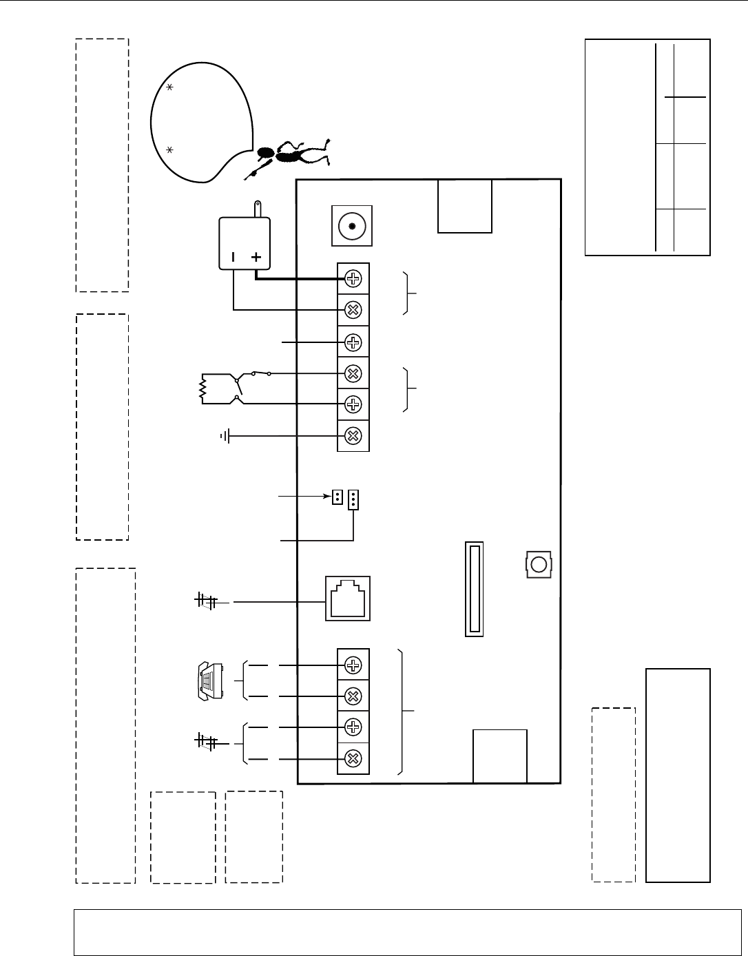
LYNX Touch Installation and Setup Guide
- 71 -
5000-100-SOC-V0
2K
OHM
EOLR
POWER SUPPLY
CONNECTOR
HARD
WIRED
ZONE
WEEKLY TESTING IS REQUIRED TO ENSURE
PROPER OPERATION OF THIS SYSTEM
PREMISES
TELEPHONE
INCOMING
PHONE LINE
INCOMING
PHONE LINE
H/S T
H/S R
RING
TIP
EGND
EARTH GROUND
HWZ1
TRIG
GND
GND
+9VDC
300-04705 or 300-04065
(300-04063 CANADA)
POWER SUPPLY
9V, 2.7A
STANDARD CAPACITY
BATTERY CONNECTOR
SUPER HIGH CAPACITY
BATTERY CONNECTOR
LYNX TOUCH SERIES SUMMARY OF CONNECTIONS
ZONES POWER
PHONE
TRIGGER OUTPUT (NEG)
(3ma)
THIS DEVICE COMPLIES WITH PART 15 OF FCC RULES. OPERATION IS
SUBJECT TO THE FOLLOWING TWO CONDITIONS: (1) THIS DEVICE MAY
NOT CAUSE HARMFUL INTERFERENCE, AND (2) THIS DEVICE MUST
ACCEPT ANY INTERFERENCE RECEIVED, INCLUDING INTERFERENCE
THAT MAY CAUSE UNDESIRED OPERATION.
THIS EQUIPMENT SHOULD BE INSTALLED IN ACCORDANCE WITH THE NATIONAL FIRE
PROTECTION ASSOCIATION STANDARDS ANSI/NFPA 70 NATONAL ELECTRIC CODE AND
NFPA 72 NATIONAL FIRE ALARM CODE, CHAPTER 2 (NATIONAL FIRE PROTECTION
ASSOC., BATTERY MARCH PARK, QUINCY, MA 02169). PRINTED INFORMATION
ESCRIBING PROPER INSTALLATION, EVACUATION PLANNING AND REPAIR SERVICE IS TO
BE PROVIDED WITH THIS EQUIPMENT.
THE LYNX TOUCH CONTROLS ARE COMPATIBLE WITH THE
FOLLOWING INTEGRAL RECHARGEABLE BATTERY PACKS:
REPLACE EVERY FOUR YEARS
P/N 300-03864-1/LYNXRCHKIT-SC
P/N 300-03866/LYNXRCHKIT-SHA
COMPLIES WITH FCC RULES, PART 68
FCC REGISTRATION No. AC3AL05BL5000
RINGER EQUIVALENCE: 0.5B
RINGTIP RING TIP
TAMPER
SWITCH
TELCO
JACK
EDGE
CONNECT
(FUTURE
USE)
EDGE
CONNECT
(FUTURE
USE)
GSMVLP5/ILP5
RECEPTACLE
NOTE: THE HARDWIRE ZONE CANNOT BEUSED AS A FIRE ZONE.
UL INSTALLATIONS
THE MINIMUM WIRE
SIZE USED FOR
TELEPHONE
INSTALLATIONS
MUST BE #26 GAGE
WARNING
TO PREVENT RISK OF
SHOCK, DISCONNECT
TELEPHONE LINE
AT TELECOM JACK
BEFORE SERVICING
THIS UNIT
LYNX TOUCH SERIES ALSO COMPLIES WITH THE FOLLOWING:
CANADIAN STANDARDS ASSOCIATION (CSA) C22.1,
CANADIAN ELECTRICAL CODE, PART 1, SAFETY STANDARD
FOR ELECTRICAL INSTALLATIONS AND CAN/ULC-S540
INSTALLATION OF RESIDENTIAL FIRE WARNING SYSTEMS.
CIRCUIT
(ZONE)
CONTROL UNIT
DELAY-SEC
SMOKE DETECTOR
MODEL DELAY-SEC
THIS UNIT MAY BE PROGRAMMED TO INCLUDE AN ALARM
VERIFICATION FEATURE THAT WILL RESULT IN A DELAY OF THE
SYSTEM ALARM SIGNAL FROM THE INDICATED FIRE CIRCUITS.
THE TOTAL DELAY (CONTROL UNIT PLUS SMOKE DETECTORS)
SHALL NOT EXCEED 60 SECONDS. NO OTHER INITIATING
DEVICES SHALL BE CONNECTED TO THESE CIRCUITS UNLESS
APPROVED BY THE LOCAL AUTHORITY HAVING JURISDICTION.
WARNING
5806W3 10 seconds30 seconds
02 - 48
ZT16
Be sure to observe
polarity when
connecting the
power supply to
the terminal strip.
IMPORTANT
Notes: Connection of the fire alarm signal to a fire alarm headquarters or a central station shall be permitted with the
approval of the local authority having jurisdiction. The burglar alarm signal shall not be connected to a police
emergency number. The System must be checked by a qualified technician once every three years

WARRANTY INFORMATION
Fort the latest warranty information, please visit:
www.honeywell.com/security/hsc/resources/wa
2 Corporate Center Drive, Suite 100
P.O. Box 9040, Melville, NY 11747
Copyright © 2011 Honeywell International Inc.
www.honeywell.com/security
Ê800-06834MŠ
800-06834 1/11 Rev. A